EP1281922B2 - Microcomponent chemical process sheet architecture - Google Patents
Microcomponent chemical process sheet architecture Download PDFInfo
- Publication number
- EP1281922B2 EP1281922B2 EP02025176A EP02025176A EP1281922B2 EP 1281922 B2 EP1281922 B2 EP 1281922B2 EP 02025176 A EP02025176 A EP 02025176A EP 02025176 A EP02025176 A EP 02025176A EP 1281922 B2 EP1281922 B2 EP 1281922B2
- Authority
- EP
- European Patent Office
- Prior art keywords
- laminate
- heat
- microchannels
- chemical
- microcomponent
- Prior art date
- Legal status (The legal status is an assumption and is not a legal conclusion. Google has not performed a legal analysis and makes no representation as to the accuracy of the status listed.)
- Expired - Lifetime
Links
Images


Classifications
-
- B—PERFORMING OPERATIONS; TRANSPORTING
- B01—PHYSICAL OR CHEMICAL PROCESSES OR APPARATUS IN GENERAL
- B01B—BOILING; BOILING APPARATUS ; EVAPORATION; EVAPORATION APPARATUS
- B01B1/00—Boiling; Boiling apparatus for physical or chemical purposes ; Evaporation in general
- B01B1/005—Evaporation for physical or chemical purposes; Evaporation apparatus therefor, e.g. evaporation of liquids for gas phase reactions
-
- B—PERFORMING OPERATIONS; TRANSPORTING
- B01—PHYSICAL OR CHEMICAL PROCESSES OR APPARATUS IN GENERAL
- B01F—MIXING, e.g. DISSOLVING, EMULSIFYING OR DISPERSING
- B01F25/00—Flow mixers; Mixers for falling materials, e.g. solid particles
- B01F25/40—Static mixers
- B01F25/42—Static mixers in which the mixing is affected by moving the components jointly in changing directions, e.g. in tubes provided with baffles or obstructions
- B01F25/421—Static mixers in which the mixing is affected by moving the components jointly in changing directions, e.g. in tubes provided with baffles or obstructions by moving the components in a convoluted or labyrinthine path
- B01F25/422—Static mixers in which the mixing is affected by moving the components jointly in changing directions, e.g. in tubes provided with baffles or obstructions by moving the components in a convoluted or labyrinthine path between stacked plates, e.g. grooved or perforated plates
-
- B—PERFORMING OPERATIONS; TRANSPORTING
- B01—PHYSICAL OR CHEMICAL PROCESSES OR APPARATUS IN GENERAL
- B01F—MIXING, e.g. DISSOLVING, EMULSIFYING OR DISPERSING
- B01F33/00—Other mixers; Mixing plants; Combinations of mixers
- B01F33/30—Micromixers
-
- B—PERFORMING OPERATIONS; TRANSPORTING
- B01—PHYSICAL OR CHEMICAL PROCESSES OR APPARATUS IN GENERAL
- B01J—CHEMICAL OR PHYSICAL PROCESSES, e.g. CATALYSIS OR COLLOID CHEMISTRY; THEIR RELEVANT APPARATUS
- B01J19/00—Chemical, physical or physico-chemical processes in general; Their relevant apparatus
- B01J19/0093—Microreactors, e.g. miniaturised or microfabricated reactors
-
- C—CHEMISTRY; METALLURGY
- C01—INORGANIC CHEMISTRY
- C01B—NON-METALLIC ELEMENTS; COMPOUNDS THEREOF; METALLOIDS OR COMPOUNDS THEREOF NOT COVERED BY SUBCLASS C01C
- C01B3/00—Hydrogen; Gaseous mixtures containing hydrogen; Separation of hydrogen from mixtures containing it; Purification of hydrogen; Reversible storage of hydrogen
- C01B3/02—Production of hydrogen; Production of gaseous mixtures containing hydrogen
- C01B3/32—Production of hydrogen; Production of gaseous mixtures containing hydrogen by reaction of gaseous or liquid organic compounds with gasifying agents, e.g. water, carbon dioxide or air
- C01B3/34—Production of hydrogen; Production of gaseous mixtures containing hydrogen by reaction of gaseous or liquid organic compounds with gasifying agents, e.g. water, carbon dioxide or air by reaction of hydrocarbons with gasifying agents
- C01B3/48—Production of hydrogen; Production of gaseous mixtures containing hydrogen by reaction of gaseous or liquid organic compounds with gasifying agents, e.g. water, carbon dioxide or air by reaction of hydrocarbons with gasifying agents followed by reaction of water vapour with carbon monoxide
-
- F—MECHANICAL ENGINEERING; LIGHTING; HEATING; WEAPONS; BLASTING
- F01—MACHINES OR ENGINES IN GENERAL; ENGINE PLANTS IN GENERAL; STEAM ENGINES
- F01K—STEAM ENGINE PLANTS; STEAM ACCUMULATORS; ENGINE PLANTS NOT OTHERWISE PROVIDED FOR; ENGINES USING SPECIAL WORKING FLUIDS OR CYCLES
- F01K13/00—General layout or general methods of operation of complete plants
-
- F—MECHANICAL ENGINEERING; LIGHTING; HEATING; WEAPONS; BLASTING
- F02—COMBUSTION ENGINES; HOT-GAS OR COMBUSTION-PRODUCT ENGINE PLANTS
- F02C—GAS-TURBINE PLANTS; AIR INTAKES FOR JET-PROPULSION PLANTS; CONTROLLING FUEL SUPPLY IN AIR-BREATHING JET-PROPULSION PLANTS
- F02C7/00—Features, components parts, details or accessories, not provided for in, or of interest apart form groups F02C1/00 - F02C6/00; Air intakes for jet-propulsion plants
- F02C7/08—Heating air supply before combustion, e.g. by exhaust gases
-
- F—MECHANICAL ENGINEERING; LIGHTING; HEATING; WEAPONS; BLASTING
- F02—COMBUSTION ENGINES; HOT-GAS OR COMBUSTION-PRODUCT ENGINE PLANTS
- F02G—HOT GAS OR COMBUSTION-PRODUCT POSITIVE-DISPLACEMENT ENGINE PLANTS; USE OF WASTE HEAT OF COMBUSTION ENGINES; NOT OTHERWISE PROVIDED FOR
- F02G1/00—Hot gas positive-displacement engine plants
- F02G1/04—Hot gas positive-displacement engine plants of closed-cycle type
- F02G1/043—Hot gas positive-displacement engine plants of closed-cycle type the engine being operated by expansion and contraction of a mass of working gas which is heated and cooled in one of a plurality of constantly communicating expansible chambers, e.g. Stirling cycle type engines
-
- F—MECHANICAL ENGINEERING; LIGHTING; HEATING; WEAPONS; BLASTING
- F25—REFRIGERATION OR COOLING; COMBINED HEATING AND REFRIGERATION SYSTEMS; HEAT PUMP SYSTEMS; MANUFACTURE OR STORAGE OF ICE; LIQUEFACTION SOLIDIFICATION OF GASES
- F25B—REFRIGERATION MACHINES, PLANTS OR SYSTEMS; COMBINED HEATING AND REFRIGERATION SYSTEMS; HEAT PUMP SYSTEMS
- F25B9/00—Compression machines, plants or systems, in which the refrigerant is air or other gas of low boiling point
-
- F—MECHANICAL ENGINEERING; LIGHTING; HEATING; WEAPONS; BLASTING
- F28—HEAT EXCHANGE IN GENERAL
- F28D—HEAT-EXCHANGE APPARATUS, NOT PROVIDED FOR IN ANOTHER SUBCLASS, IN WHICH THE HEAT-EXCHANGE MEDIA DO NOT COME INTO DIRECT CONTACT
- F28D9/00—Heat-exchange apparatus having stationary plate-like or laminated conduit assemblies for both heat-exchange media, the media being in contact with different sides of a conduit wall
-
- H—ELECTRICITY
- H05—ELECTRIC TECHNIQUES NOT OTHERWISE PROVIDED FOR
- H05K—PRINTED CIRCUITS; CASINGS OR CONSTRUCTIONAL DETAILS OF ELECTRIC APPARATUS; MANUFACTURE OF ASSEMBLAGES OF ELECTRICAL COMPONENTS
- H05K7/00—Constructional details common to different types of electric apparatus
- H05K7/20—Modifications to facilitate cooling, ventilating, or heating
- H05K7/20218—Modifications to facilitate cooling, ventilating, or heating using a liquid coolant without phase change in electronic enclosures
- H05K7/20254—Cold plates transferring heat from heat source to coolant
-
- B—PERFORMING OPERATIONS; TRANSPORTING
- B01—PHYSICAL OR CHEMICAL PROCESSES OR APPARATUS IN GENERAL
- B01J—CHEMICAL OR PHYSICAL PROCESSES, e.g. CATALYSIS OR COLLOID CHEMISTRY; THEIR RELEVANT APPARATUS
- B01J2219/00—Chemical, physical or physico-chemical processes in general; Their relevant apparatus
- B01J2219/00781—Aspects relating to microreactors
- B01J2219/00783—Laminate assemblies, i.e. the reactor comprising a stack of plates
-
- B—PERFORMING OPERATIONS; TRANSPORTING
- B01—PHYSICAL OR CHEMICAL PROCESSES OR APPARATUS IN GENERAL
- B01J—CHEMICAL OR PHYSICAL PROCESSES, e.g. CATALYSIS OR COLLOID CHEMISTRY; THEIR RELEVANT APPARATUS
- B01J2219/00—Chemical, physical or physico-chemical processes in general; Their relevant apparatus
- B01J2219/00781—Aspects relating to microreactors
- B01J2219/00819—Materials of construction
- B01J2219/00822—Metal
-
- B—PERFORMING OPERATIONS; TRANSPORTING
- B01—PHYSICAL OR CHEMICAL PROCESSES OR APPARATUS IN GENERAL
- B01J—CHEMICAL OR PHYSICAL PROCESSES, e.g. CATALYSIS OR COLLOID CHEMISTRY; THEIR RELEVANT APPARATUS
- B01J2219/00—Chemical, physical or physico-chemical processes in general; Their relevant apparatus
- B01J2219/00781—Aspects relating to microreactors
- B01J2219/00819—Materials of construction
- B01J2219/00824—Ceramic
-
- B—PERFORMING OPERATIONS; TRANSPORTING
- B01—PHYSICAL OR CHEMICAL PROCESSES OR APPARATUS IN GENERAL
- B01J—CHEMICAL OR PHYSICAL PROCESSES, e.g. CATALYSIS OR COLLOID CHEMISTRY; THEIR RELEVANT APPARATUS
- B01J2219/00—Chemical, physical or physico-chemical processes in general; Their relevant apparatus
- B01J2219/00781—Aspects relating to microreactors
- B01J2219/00819—Materials of construction
- B01J2219/00833—Plastic
-
- B—PERFORMING OPERATIONS; TRANSPORTING
- B01—PHYSICAL OR CHEMICAL PROCESSES OR APPARATUS IN GENERAL
- B01J—CHEMICAL OR PHYSICAL PROCESSES, e.g. CATALYSIS OR COLLOID CHEMISTRY; THEIR RELEVANT APPARATUS
- B01J2219/00—Chemical, physical or physico-chemical processes in general; Their relevant apparatus
- B01J2219/00781—Aspects relating to microreactors
- B01J2219/00819—Materials of construction
- B01J2219/00835—Comprising catalytically active material
-
- B—PERFORMING OPERATIONS; TRANSPORTING
- B01—PHYSICAL OR CHEMICAL PROCESSES OR APPARATUS IN GENERAL
- B01J—CHEMICAL OR PHYSICAL PROCESSES, e.g. CATALYSIS OR COLLOID CHEMISTRY; THEIR RELEVANT APPARATUS
- B01J2219/00—Chemical, physical or physico-chemical processes in general; Their relevant apparatus
- B01J2219/00781—Aspects relating to microreactors
- B01J2219/00819—Materials of construction
- B01J2219/00844—Comprising porous material
-
- B—PERFORMING OPERATIONS; TRANSPORTING
- B01—PHYSICAL OR CHEMICAL PROCESSES OR APPARATUS IN GENERAL
- B01J—CHEMICAL OR PHYSICAL PROCESSES, e.g. CATALYSIS OR COLLOID CHEMISTRY; THEIR RELEVANT APPARATUS
- B01J2219/00—Chemical, physical or physico-chemical processes in general; Their relevant apparatus
- B01J2219/00781—Aspects relating to microreactors
- B01J2219/00851—Additional features
- B01J2219/00869—Microreactors placed in parallel, on the same or on different supports
-
- B—PERFORMING OPERATIONS; TRANSPORTING
- B01—PHYSICAL OR CHEMICAL PROCESSES OR APPARATUS IN GENERAL
- B01J—CHEMICAL OR PHYSICAL PROCESSES, e.g. CATALYSIS OR COLLOID CHEMISTRY; THEIR RELEVANT APPARATUS
- B01J2219/00—Chemical, physical or physico-chemical processes in general; Their relevant apparatus
- B01J2219/00781—Aspects relating to microreactors
- B01J2219/00873—Heat exchange
-
- B—PERFORMING OPERATIONS; TRANSPORTING
- B01—PHYSICAL OR CHEMICAL PROCESSES OR APPARATUS IN GENERAL
- B01J—CHEMICAL OR PHYSICAL PROCESSES, e.g. CATALYSIS OR COLLOID CHEMISTRY; THEIR RELEVANT APPARATUS
- B01J2219/00—Chemical, physical or physico-chemical processes in general; Their relevant apparatus
- B01J2219/00781—Aspects relating to microreactors
- B01J2219/00891—Feeding or evacuation
-
- B—PERFORMING OPERATIONS; TRANSPORTING
- B01—PHYSICAL OR CHEMICAL PROCESSES OR APPARATUS IN GENERAL
- B01J—CHEMICAL OR PHYSICAL PROCESSES, e.g. CATALYSIS OR COLLOID CHEMISTRY; THEIR RELEVANT APPARATUS
- B01J2219/00—Chemical, physical or physico-chemical processes in general; Their relevant apparatus
- B01J2219/00781—Aspects relating to microreactors
- B01J2219/00905—Separation
- B01J2219/00907—Separation using membranes
-
- B—PERFORMING OPERATIONS; TRANSPORTING
- B01—PHYSICAL OR CHEMICAL PROCESSES OR APPARATUS IN GENERAL
- B01J—CHEMICAL OR PHYSICAL PROCESSES, e.g. CATALYSIS OR COLLOID CHEMISTRY; THEIR RELEVANT APPARATUS
- B01J2219/00—Chemical, physical or physico-chemical processes in general; Their relevant apparatus
- B01J2219/00781—Aspects relating to microreactors
- B01J2219/00905—Separation
- B01J2219/00918—Separation by adsorption
-
- C—CHEMISTRY; METALLURGY
- C01—INORGANIC CHEMISTRY
- C01B—NON-METALLIC ELEMENTS; COMPOUNDS THEREOF; METALLOIDS OR COMPOUNDS THEREOF NOT COVERED BY SUBCLASS C01C
- C01B2203/00—Integrated processes for the production of hydrogen or synthesis gas
- C01B2203/02—Processes for making hydrogen or synthesis gas
- C01B2203/025—Processes for making hydrogen or synthesis gas containing a partial oxidation step
- C01B2203/0261—Processes for making hydrogen or synthesis gas containing a partial oxidation step containing a catalytic partial oxidation step [CPO]
-
- C—CHEMISTRY; METALLURGY
- C01—INORGANIC CHEMISTRY
- C01B—NON-METALLIC ELEMENTS; COMPOUNDS THEREOF; METALLOIDS OR COMPOUNDS THEREOF NOT COVERED BY SUBCLASS C01C
- C01B2203/00—Integrated processes for the production of hydrogen or synthesis gas
- C01B2203/02—Processes for making hydrogen or synthesis gas
- C01B2203/0283—Processes for making hydrogen or synthesis gas containing a CO-shift step, i.e. a water gas shift step
-
- C—CHEMISTRY; METALLURGY
- C01—INORGANIC CHEMISTRY
- C01B—NON-METALLIC ELEMENTS; COMPOUNDS THEREOF; METALLOIDS OR COMPOUNDS THEREOF NOT COVERED BY SUBCLASS C01C
- C01B2203/00—Integrated processes for the production of hydrogen or synthesis gas
- C01B2203/04—Integrated processes for the production of hydrogen or synthesis gas containing a purification step for the hydrogen or the synthesis gas
- C01B2203/0435—Catalytic purification
- C01B2203/044—Selective oxidation of carbon monoxide
-
- C—CHEMISTRY; METALLURGY
- C01—INORGANIC CHEMISTRY
- C01B—NON-METALLIC ELEMENTS; COMPOUNDS THEREOF; METALLOIDS OR COMPOUNDS THEREOF NOT COVERED BY SUBCLASS C01C
- C01B2203/00—Integrated processes for the production of hydrogen or synthesis gas
- C01B2203/04—Integrated processes for the production of hydrogen or synthesis gas containing a purification step for the hydrogen or the synthesis gas
- C01B2203/0465—Composition of the impurity
- C01B2203/047—Composition of the impurity the impurity being carbon monoxide
-
- C—CHEMISTRY; METALLURGY
- C01—INORGANIC CHEMISTRY
- C01B—NON-METALLIC ELEMENTS; COMPOUNDS THEREOF; METALLOIDS OR COMPOUNDS THEREOF NOT COVERED BY SUBCLASS C01C
- C01B2203/00—Integrated processes for the production of hydrogen or synthesis gas
- C01B2203/06—Integration with other chemical processes
- C01B2203/066—Integration with other chemical processes with fuel cells
-
- C—CHEMISTRY; METALLURGY
- C01—INORGANIC CHEMISTRY
- C01B—NON-METALLIC ELEMENTS; COMPOUNDS THEREOF; METALLOIDS OR COMPOUNDS THEREOF NOT COVERED BY SUBCLASS C01C
- C01B2203/00—Integrated processes for the production of hydrogen or synthesis gas
- C01B2203/08—Methods of heating or cooling
- C01B2203/0805—Methods of heating the process for making hydrogen or synthesis gas
-
- C—CHEMISTRY; METALLURGY
- C01—INORGANIC CHEMISTRY
- C01B—NON-METALLIC ELEMENTS; COMPOUNDS THEREOF; METALLOIDS OR COMPOUNDS THEREOF NOT COVERED BY SUBCLASS C01C
- C01B2203/00—Integrated processes for the production of hydrogen or synthesis gas
- C01B2203/08—Methods of heating or cooling
- C01B2203/0805—Methods of heating the process for making hydrogen or synthesis gas
- C01B2203/0838—Methods of heating the process for making hydrogen or synthesis gas by heat exchange with exothermic reactions, other than by combustion of fuel
-
- C—CHEMISTRY; METALLURGY
- C01—INORGANIC CHEMISTRY
- C01B—NON-METALLIC ELEMENTS; COMPOUNDS THEREOF; METALLOIDS OR COMPOUNDS THEREOF NOT COVERED BY SUBCLASS C01C
- C01B2203/00—Integrated processes for the production of hydrogen or synthesis gas
- C01B2203/08—Methods of heating or cooling
- C01B2203/0872—Methods of cooling
- C01B2203/0883—Methods of cooling by indirect heat exchange
-
- C—CHEMISTRY; METALLURGY
- C01—INORGANIC CHEMISTRY
- C01B—NON-METALLIC ELEMENTS; COMPOUNDS THEREOF; METALLOIDS OR COMPOUNDS THEREOF NOT COVERED BY SUBCLASS C01C
- C01B2203/00—Integrated processes for the production of hydrogen or synthesis gas
- C01B2203/08—Methods of heating or cooling
- C01B2203/0872—Methods of cooling
- C01B2203/0888—Methods of cooling by evaporation of a fluid
- C01B2203/0894—Generation of steam
-
- C—CHEMISTRY; METALLURGY
- C01—INORGANIC CHEMISTRY
- C01B—NON-METALLIC ELEMENTS; COMPOUNDS THEREOF; METALLOIDS OR COMPOUNDS THEREOF NOT COVERED BY SUBCLASS C01C
- C01B2203/00—Integrated processes for the production of hydrogen or synthesis gas
- C01B2203/10—Catalysts for performing the hydrogen forming reactions
- C01B2203/1005—Arrangement or shape of catalyst
- C01B2203/1035—Catalyst coated on equipment surfaces, e.g. reactor walls
-
- C—CHEMISTRY; METALLURGY
- C01—INORGANIC CHEMISTRY
- C01B—NON-METALLIC ELEMENTS; COMPOUNDS THEREOF; METALLOIDS OR COMPOUNDS THEREOF NOT COVERED BY SUBCLASS C01C
- C01B2203/00—Integrated processes for the production of hydrogen or synthesis gas
- C01B2203/10—Catalysts for performing the hydrogen forming reactions
- C01B2203/1041—Composition of the catalyst
- C01B2203/1047—Group VIII metal catalysts
- C01B2203/1052—Nickel or cobalt catalysts
-
- C—CHEMISTRY; METALLURGY
- C01—INORGANIC CHEMISTRY
- C01B—NON-METALLIC ELEMENTS; COMPOUNDS THEREOF; METALLOIDS OR COMPOUNDS THEREOF NOT COVERED BY SUBCLASS C01C
- C01B2203/00—Integrated processes for the production of hydrogen or synthesis gas
- C01B2203/10—Catalysts for performing the hydrogen forming reactions
- C01B2203/1041—Composition of the catalyst
- C01B2203/1047—Group VIII metal catalysts
- C01B2203/1064—Platinum group metal catalysts
-
- C—CHEMISTRY; METALLURGY
- C01—INORGANIC CHEMISTRY
- C01B—NON-METALLIC ELEMENTS; COMPOUNDS THEREOF; METALLOIDS OR COMPOUNDS THEREOF NOT COVERED BY SUBCLASS C01C
- C01B2203/00—Integrated processes for the production of hydrogen or synthesis gas
- C01B2203/12—Feeding the process for making hydrogen or synthesis gas
- C01B2203/1205—Composition of the feed
- C01B2203/1211—Organic compounds or organic mixtures used in the process for making hydrogen or synthesis gas
- C01B2203/1235—Hydrocarbons
- C01B2203/1241—Natural gas or methane
-
- C—CHEMISTRY; METALLURGY
- C01—INORGANIC CHEMISTRY
- C01B—NON-METALLIC ELEMENTS; COMPOUNDS THEREOF; METALLOIDS OR COMPOUNDS THEREOF NOT COVERED BY SUBCLASS C01C
- C01B2203/00—Integrated processes for the production of hydrogen or synthesis gas
- C01B2203/12—Feeding the process for making hydrogen or synthesis gas
- C01B2203/1258—Pre-treatment of the feed
- C01B2203/1264—Catalytic pre-treatment of the feed
- C01B2203/127—Catalytic desulfurisation
-
- C—CHEMISTRY; METALLURGY
- C01—INORGANIC CHEMISTRY
- C01B—NON-METALLIC ELEMENTS; COMPOUNDS THEREOF; METALLOIDS OR COMPOUNDS THEREOF NOT COVERED BY SUBCLASS C01C
- C01B2203/00—Integrated processes for the production of hydrogen or synthesis gas
- C01B2203/80—Aspect of integrated processes for the production of hydrogen or synthesis gas not covered by groups C01B2203/02 - C01B2203/1695
-
- C—CHEMISTRY; METALLURGY
- C01—INORGANIC CHEMISTRY
- C01B—NON-METALLIC ELEMENTS; COMPOUNDS THEREOF; METALLOIDS OR COMPOUNDS THEREOF NOT COVERED BY SUBCLASS C01C
- C01B2203/00—Integrated processes for the production of hydrogen or synthesis gas
- C01B2203/80—Aspect of integrated processes for the production of hydrogen or synthesis gas not covered by groups C01B2203/02 - C01B2203/1695
- C01B2203/82—Several process steps of C01B2203/02 - C01B2203/08 integrated into a single apparatus
-
- F—MECHANICAL ENGINEERING; LIGHTING; HEATING; WEAPONS; BLASTING
- F02—COMBUSTION ENGINES; HOT-GAS OR COMBUSTION-PRODUCT ENGINE PLANTS
- F02G—HOT GAS OR COMBUSTION-PRODUCT POSITIVE-DISPLACEMENT ENGINE PLANTS; USE OF WASTE HEAT OF COMBUSTION ENGINES; NOT OTHERWISE PROVIDED FOR
- F02G2254/00—Heat inputs
- F02G2254/10—Heat inputs by burners
- F02G2254/11—Catalytic burners
-
- F—MECHANICAL ENGINEERING; LIGHTING; HEATING; WEAPONS; BLASTING
- F25—REFRIGERATION OR COOLING; COMBINED HEATING AND REFRIGERATION SYSTEMS; HEAT PUMP SYSTEMS; MANUFACTURE OR STORAGE OF ICE; LIQUEFACTION SOLIDIFICATION OF GASES
- F25B—REFRIGERATION MACHINES, PLANTS OR SYSTEMS; COMBINED HEATING AND REFRIGERATION SYSTEMS; HEAT PUMP SYSTEMS
- F25B2309/00—Gas cycle refrigeration machines
- F25B2309/14—Compression machines, plants or systems characterised by the cycle used
- F25B2309/1401—Ericsson or Ericcson cycles
-
- F—MECHANICAL ENGINEERING; LIGHTING; HEATING; WEAPONS; BLASTING
- F28—HEAT EXCHANGE IN GENERAL
- F28F—DETAILS OF HEAT-EXCHANGE AND HEAT-TRANSFER APPARATUS, OF GENERAL APPLICATION
- F28F2260/00—Heat exchangers or heat exchange elements having special size, e.g. microstructures
- F28F2260/02—Heat exchangers or heat exchange elements having special size, e.g. microstructures having microchannels
-
- Y—GENERAL TAGGING OF NEW TECHNOLOGICAL DEVELOPMENTS; GENERAL TAGGING OF CROSS-SECTIONAL TECHNOLOGIES SPANNING OVER SEVERAL SECTIONS OF THE IPC; TECHNICAL SUBJECTS COVERED BY FORMER USPC CROSS-REFERENCE ART COLLECTIONS [XRACs] AND DIGESTS
- Y10—TECHNICAL SUBJECTS COVERED BY FORMER USPC
- Y10S—TECHNICAL SUBJECTS COVERED BY FORMER USPC CROSS-REFERENCE ART COLLECTIONS [XRACs] AND DIGESTS
- Y10S366/00—Agitating
- Y10S366/03—Micromixers: variable geometry from the pathway influences mixing/agitation of non-laminar fluid flow
Definitions
- the present invention relates to a use of a fuel processing unit and to a fuel processing method using a microcomponent sheet architecture wherein macroscale production is achieved with a plurality of microscale elements operating in parallel.
- Components exhibiting high efficiency at small scale include microchannel heat exchangers used to remove heat from electronic components.
- microscale motors for example, conventional wisdom combines microscale components in series with the result that achieving a macroscale result would require enormous effort and cost of making millions of tiny systems.
- extracting heat from combustion processes results in thermal inefficiency because of the necessary separation of combustion reactants and products from the medium to be heated, for example steam in a coal fired power plant. It has long been desired to reduce thermal inefficiency of combustion heat transfer.
- Furaya et al in JP06111838A describe a fuel cell system with an integrated reformer.
- a combustion layer provides heat to an adjacent reforming layer in which water and methanol are vaporized and reacted over a reformation catalyst to produce hydrogen.
- Hydrogen produced in the reforming layer can be led through a selective membrane to a fuel cell electrode.
- the present invention provides the use of a fuel processing unit according to claim 1.
- the laminate has a plurality of microchannels.
- the sheet architecture may be a single laminate with a plurality of separate microcomponent sections or the sheet architecture may be a plurality of laminates with one or more microcomponent sections on each laminate.
- the microcomponents include passive microcomponents, for example micro flow paths, and active components including but not limited to micropumps and microcompressors.
- Each microcomponent or plurality of like microcomponents perform at least one unit operation.
- a first laminate having a plurality of like first microcomponents is combined with at least a second laminate having a plurality of like second microcomponents thereby combining at least two unit operations to achieve a system operation.
- a laminate containing a plurality of microchannel evaporators is combined with an insulating laminate and a laminate containing a plurality of microchannel condensers, and connected to a compressor and expansion valve to obtain a macroscale heat pump.
- the present invention also provides a fuel processing method in accordance with claim 4.
- the present invention provides a use of the fuel processing unit of the invention for converting methane to hydrogen.
- the subject matter of the present invention is particularly pointed out and distinctly claimed in the concluding portion of this specification.
- both the organization and method of operation, together with further advantages and objects thereof, may best be understood by reference to the following description taken in connection with accompanying drawings wherein like reference characters refer to like elements.
- the invention typically involves use of a fuel processing unit having microcomponent sheet or laminate architecture of individual laminates wherein the fundamental structure is a laminate or laminate portion having tens to millions of microcomponents, preferably hundreds to millions, thereby enabling a laminate to provide macroscale unit operation, for example a condenser having a capacity in the kWth range, and the laminates connected, thereby combining unit operations, to form an assembly, or system, for example a chemical reactor.
- FIG. 1 shows the fundamental structure of a laminate.
- a material sheet or laminate 1 On a material sheet or laminate 1 , a plurality of microcomponents 2 are embedded onto the material sheet 1 .
- Material sheets 1 may be any solid material, but are preferably metal, ceramic, or semiconductor material.
- a material sheet 1 embedded with microcomponents 2 is a laminate.
- a laminate is also a material sheet 1 having no microcomponents or having conduits through the material sheet 1 thickness serving as a spacer or insulator.
- the microcomponents 2 can be condensers, evaporators or non-phase change heat exchangers, compressors, expansion valves, or motors. It is to be understood that while the drawings and discussion thereof are limited to specific embodiments, there is practically no limit to the types and numbers of microcomponents and combinations thereof that may be included on a laminate or material sheet 1 .
- FIG. 1 depicts microcomponents 2 on one side of the material sheet 1
- microcomponents may be embedded on both sides of the material sheet 1. Embedding on both sides may be particularly advantageous for dual fluid heat exchangers, for example feedwater preheating with condensed turbine exhaust.
- the density of microcomponents 2 on a material sheet may range from about 1 microcomponent per square centimeter to about 10 10 microcomponents per square centimeter. Within those density ranges, a range of unit lengths or unit diameters of microcomponents 2 is from about 1 micron to about 1 centimeter.
- the width W of the grooves or microchannels 3 may range from about 1 micron to about 1 millimeter and preferably range from about 10 microns to about 250 microns.
- microchannels or flow paths may be laterally closed as shown in FIG. 1 , or laterally open as shown in FIG 1a .
- the microcomponents 2 are groove sets 4 made up of a pair of headers 5 and laterals 6 .
- Laterals 6 are the grooves permitting flow between header pairs 5 .
- Laterals 6 are shown substantially perpendicular to headers 5 , but is will be apparent to one skilled in the art of microcomponents that a lateral 6 can form an angle other than 90 degrees with a header 5 .
- Headers 5 may be provided with connections 8 , which are enlarged portions of headers 5 , for receiving and sending fluid.
- the connections 8 are optional inasmuch as fluid transfer to and from the headers 5 can be accomplished within the width W of the headers 5 .
- Laterals 6 may have the same width as the headers 5 or have a different width either smaller or larger. It is preferred that the laterals 6 have smaller widths than the headers 5 .
- Embedment of microcomponents 2 or groove sets 4 may be accomplished by any microchannel forming process, but is preferably done with micromachining or photolithography. A photolithographic process is most preferred because the cost of making groove sets 4 is substantially independent of the number of groove sets 4 .
- Microchannel forming processes generally etch a surface so that resulting channels are unconfined on the etched side. Channels are closed by bonding a second laminate to the etched surface.
- the plurality of solid material lands 10 defining the laterals 6 function as heat transfer fins supporting the high heat flux observed. Each land 10 may be laterally closed as shown in FIG. 2a or laterally open as shown in FIG. 1a to permit cross flow communication.
- the lands 10 may be of any cross section including but not limited to rectangular, rhomboid, and ellipsoid cross sections.
- Laterally open lands increase flow area thereby reducing the possibility of clogging and reducing the effect of a clog should it occur.
- the definition of a lateral is less distinct especially if the lands are offset or randomly spaced. Nevertheless, the spaces between the open lands are flow paths.
- microcomponents 3 are shown without a top cover, it is preferred that the top be closed with a cover to constrain the flow of fluid to remain within the flow paths and in intimate contact with the lands 10 .
- the cover may be a plain laminate having no microcomponents, for example an insulating laminate, or it may be another microcomponent laminate.
- a single microcomponent or a set of like microcomponents is capable of performing at least one unit operation.
- a unit operation is defined as an operation that changes the state (thermodynamic state including chemical and/or physical state) of a working fluid including but not limited to condensation, evaporation, compression, pumping, heat exchanging, expansion, or chemical process, for example chemical conversion or separation.
- Chemical reactions may be endothermic or exothermic. Conversion reactions include, for example, partial oxidation and combustion.
- Separation involves receiving at least one chemical mixture having a chemical product and a product carrier and separating the chemical product from the product carrier. Examples of separations include distillation, ion exchange and solvent extraction.
- a collection of unit operations is a system.
- An example of a single microcomponent performing more than one unit operation is a microcompressor in a thermally conductive material performing both compression and heat transfer simultaneously.
- macrocompressors conduct heat as a result of compressing a gas, but that heat is small compared to the process heat, for example heat removed from a refrigerated space.
- the distinct advantage of a microcomponent is that the heat transferred simultaneous with the compression is indeed process heat thereby providing a substantially constant temperature compression (approaching an ideal isothermal compression) which results in the most efficient energy transfer/conversion.
- a further example of a system is a microchannel combustor placed upon a microchannel evaporator for vaporizing a working fluid for a heat engine.
- a system may comprise a microchannel chemical reactor placed upon an microchannel heat exchanger, preferably an evaporator, for temperature control of the chemical reaction thereby permitting control of partial oxidation chemical reactions.
- a system has a first laminate having a first plurality of microcomponents for performing at least one unit operation; attached to a second laminate having a second plurality of microcomponents for performing at least one additional unit operation; wherein the unit operation is combined with the additional unit operation and produces a system operation.
- separate unit operations may be placed on a single laminate having a first portion and at least a second portion.
- the first portion has first microcomponents for performing a unit operation and the second and subsequent portion(s) have second and subsequent microcomponents for performing another and subsequent unit operation(s).
- the unit operation is combined with the additional and/or subsequent unit operation(s) and produces a system operation.
- Microcomponents performing one unit operation can be combined in several ways with microcomponents performing another unit operation.
- several microscale pumps in parallel may feed a single heat exchanger, or one microscale pump may feed several heat exchangers in parallel.
- Similar variations with like microcomponents in series or a combination of series and parallel arrangements may be used advantageously in particular applications.
- Laminates or laminate portions are combinable into a wide variety of systems including but not limited to heat pumps, heat engines, heat pipes, thermal sources, and chemical plants, for example chemical converters and chemical separators.
- a microchannel chemical process system is one in which a chemical process unit operation is combined with at least one other unit operation.
- the use of microchannels for chemical processes permits greater control in the process that cannot be obtained in a conventional "macrochannel" large scale reactor.
- a broad range of control of temperature is made possible by use of microchannel laminates.
- microchannel chemical reactors used in a sheet architecture permit controlled temperature gradients or controlled temperature variation across a sheet of microchannels thereby permitting quenching and attainment of non-equilibrium states.
- other parameters may be closely controlled.
- microchannel geometry is useful for control of residence time, or velocity profile or both.
- Energy other than thermal energy may be used to activate a reaction or to otherwise create an environment conducive to specific desired reactions, including but not limited to electrical on field induced reactions (e.g. plasmas or aqueous phase electrochemical reactors) magnetically induced or controlled chemical reactions and sonically induced reactions.
- electrical on field induced reactions e.g. plasmas or aqueous phase electrochemical reactors
- magnetically induced or controlled chemical reactions e.g. sonically induced reactions.
- An example of providing a temperature gradient is having a sheet of parallel microchannels for a condenser or evaporator wherein adjacent microchannels are held at different pressures thereby experiencing phase change at different temperatures. With a reactor sheet having microchannels positioned in crossflow with respect to the condenser or evaporator microchannels, the reactions conditions are controllable along the length of the microchannel reactor.
- a field generator is used to induce an electric or magnetic field.
- the field generator is placed in proximity of the first laminate having reactor microchannels.
- the microchannel reactor is preferably used for reactions that do not require materials or solids that would clog the microchannels and that do not produce materials or solids that would clog the microchannels. Because the microchannel sheet architecture is capable of precise and accurate control of localized reaction conditions, for example reaction temperature and temperature gradient control at predetermined reactor location(s), it is preferred that the microchannel sheet architecture be used for reactions wherein precise control is beneficial as in partial oxidation reactions.
- Control of reaction temperature is critical for all partial oxidation reactions and control of residence time may be critical depending upon the reaction and reaction conditions.
- partial oxidation of methane to hydrogen requires both control of temperature and residence time to avoid combustion of methane to carbon dioxide and water.
- Temperature control may be achieved in any of several ways. For example when a first sheet or laminate is in a cross flow relationship to a second sheet or laminate, a temperature gradient along a flow direction of the first laminate is maintained by controlling temperature of coolant within particular microchannels or microcomponents. Geometry of the microchannels, e.g. variable flow path width, cross sectional area and/or shape may be used to optimize heat transfer to or from a chemical process sheet or laminate.
- a microchannel reactor 900 useful for performing the invention has a first laminate 902 reactor that receives reactants 904 , fuel (methane) and oxygen, and rejects reaction products 906 .
- the first laminate 902 contains microchannels 908 .
- the microchannels 908 contain a coating 910 on a surface of the microchannels 908 .
- the coating is preferably a catalyst, or a catalyst support with catalyst or multiple catalysts.
- the coating is a permeate or a material that influences wetability or contact angle, coating materials include but are not limited to catalytic metals, for example nickel, platinum, and rhodium.
- a second laminate 912 has microchannels 914 for receiving a fluid 916 , and rejecting fluid 918 .
- the cooling medium microchannels 912 is in close proximity with reaction microchannels 902 .
- Cooling medium microchannels 912 and reaction microchannels 902 may be in direct contact, or may have a gap therebetween. The gap may be open or filled with an insulating material.
- flow of cooling medium with respect to reactants is preferably counterflow, but may be parallel or crossflow.
- a single phase fluid is used for removing heat wherein no phase change occurs.
- a fuel supply is necessary.
- the catalysts may be poisoned by carbon monoxide or other contaminants.
- a fuel processing unit may incorporate partial oxidation reactors, shift reactors (convert CO and H 2 O to additional H 2 and CO 2 ), a sulfur scrubber, a preferential oxidation reactor for removing remaining CO or a combination thereof.
- a fuel processing unit incorporating each of these features is shown in FIG. 4 .
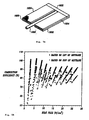
- FIG. 5a An experiment was conducted to demonstrate a combustion reactor not in accordance with the invention using microchannel components as shown in FIG. 5a .
- Fuel and oxidizer enter a ceramic tube 1600 . Ignition is accomplished with an electronic igniter (not shown). Combustion products pass through a header 1602 into gas flow laminates 1604. Water is passed through water flow laminates 1606 .
- microchannels within the laminates 1604 , 1606 were made with electro-discharge machining in stainless steel. Grooves were nominally 300 micrometers wide by 500 micrometers deep and 34 millimeters long. The area for heat transfer was 9.98 cm 2 .
- the fuel was methane and the oxidizer was oxygen.
- a mass flow ratio of precisely two moles of oxygen per mole of methane was maintained so that stoichiometric combustion occurred.
- Water flow rate was between about 1.28 g/s (1.6 gal/hr) and 1.32 g/s.
- Results in the form of combustion efficiency are shown in FIG. 16b.
- the combustor efficiency is about 92 % based upon the higher heating value (HHV) of the fuel.
- the combustion efficiency about 93% based upon the lower heating value (LHV) of the fuel or 85% based upon HHV.
Landscapes
- Chemical & Material Sciences (AREA)
- Engineering & Computer Science (AREA)
- Chemical Kinetics & Catalysis (AREA)
- General Engineering & Computer Science (AREA)
- Combustion & Propulsion (AREA)
- Mechanical Engineering (AREA)
- Organic Chemistry (AREA)
- Physics & Mathematics (AREA)
- Thermal Sciences (AREA)
- Microelectronics & Electronic Packaging (AREA)
- Health & Medical Sciences (AREA)
- General Health & Medical Sciences (AREA)
- Dispersion Chemistry (AREA)
- Inorganic Chemistry (AREA)
- Physical Or Chemical Processes And Apparatus (AREA)
- Hydrogen, Water And Hydrids (AREA)
- Catalysts (AREA)
- Micromachines (AREA)
Abstract
Description
- The present invention relates to a use of a fuel processing unit and to a fuel processing method using a microcomponent sheet architecture wherein macroscale production is achieved with a plurality of microscale elements operating in parallel.
- In order to continually improve physical standards of living for greater numbers of people, it is necessary to achieve more results with fewer resources. From the industrial revolution through the present, economies of scale have resulted in very large components and systems of capital equipment and central operating facilities. Central facilities have the further disadvantage of requiring distribution systems which have their own capital costs and efficiency losses. Nevertheless, historically, central systems have exhibited cost advantages that supported their use. Smaller distributed components and systems are made having higher unit costs and used in applications where the substantial capital cost of a larger, more efficient component or system is not justified. Thus, there is a need for components and systems that can be made of a size appropriate for the desired capacity and can avoid the need for a distribution system yet achieve the efficiency of the larger scale components and systems.
- Components exhibiting high efficiency at small scale include microchannel heat exchangers used to remove heat from electronic components.
-
US-A- 5,115,858, May 26, 1992 , MICRO-CHANNEL WAFER COOLING CHUCK, Fitch et al. discusses a 3M micro-channel stock used to cool a wafer by passing a liquid coolant through alternate channels. A high heat transfer fluid is passed through the remaining channels to remove the heat. -
US-A 4,998,580, March 12, 1991 , CONDENSER WITH SMALL HYDRAULIC DIAMETER FLOW PATH, Guntly et al. shows a condenser for use in air conditioning or refrigeration systems. Construction of the condenser is corrugated metal and flat strips. -
US-A- 5,016,707, May 21, 1991 , MULTI-PASS CROSSFLOW JET IMPINGEMENT HEAT EXCHANGER, Nguyen describes a crossflow heat exchanger and a construction thereof by stacking multiple core and spacer plates. -
US-A-5,296,775, March 22, 1994 , COOLING MICROFAN ARRANGEMENTS AND PROCESS, Cronin et al. discusses a micro electronic cooling fan in combination with ridges or fins, e.g., open channels. - The art as shown in the above referenced patents teaches design of specific heat exchange equipment requiring substantial fabrication for individual pieces of heat exchange equipment. Use of this equipment for medium to large scale operations would require the fabrication of multiple heat exchangers wherein the cost increases linearly with the number of heat exchangers.
- Moreover, fabrication of a system is considered complicated and expensive on a microscale. Although it is presently possible to make microscale motors, for example, conventional wisdom combines microscale components in series with the result that achieving a macroscale result would require enormous effort and cost of making millions of tiny systems.
- Thus, there is a need for a heat exchanger, as well as other system components, and a fabrication technique that permits fabrication of a necessary number of heat exchangers and other components for an application wherein the unit cost per component is sufficiently low that extension to multiple components is achieved with much less cost, and wherein combination of components to form systems for macroscale results is also achieved with low cost.
- It has long been a challenge to utilize methane for anything other than burning. It is known that methane can produce hydrogen (Hickman and Schmidt, "Production of Syngas by Direct Catalytic Oxidation of Methane", Science, Vol. 259, January 15, 1993) by using partial oxidation, but that has only been achieved on a small scale with laboratory methods that have yet to be scaled up to useful production quantities. Hydrogen is also produced by steam reforming which requires large capital intensive plants and equipment to be cost effective. Hence, there is still a need for an apparatus and method to produce hydrogen from methane without large capital expense.
- Further, extracting heat from combustion processes results in thermal inefficiency because of the necessary separation of combustion reactants and products from the medium to be heated, for example steam in a coal fired power plant. It has long been desired to reduce thermal inefficiency of combustion heat transfer.
- In addition to chemical conversions, chemical separations are also subject to inefficiencies that limit product yield. More specifically, product purity is related to the number of separation stages which is limited by the capital expenditure for each stage.
- In a process wherein conversion requires temperature control, very often temperature control is achieved by excess reactant(s) or diluent(s). Hence the temperature control problem is shifted to a downstream separation problem for separating product from unreacted reactant(s) or diluent(s) and/or recovering unreacted reactant(s). Hence there is a need for a method or apparatus permitting conversions requiring temperature control to be carried out without the need for excess reactant(s) or diluent(s).
- Furaya et al in
JP06111838A - The present invention provides the use of a fuel processing unit according to claim 1.
- In a sheet architecture for example, the laminate has a plurality of microchannels. The sheet architecture may be a single laminate with a plurality of separate microcomponent sections or the sheet architecture may be a plurality of laminates with one or more microcomponent sections on each laminate. The microcomponents include passive microcomponents, for example micro flow paths, and active components including but not limited to micropumps and microcompressors.
- Each microcomponent or plurality of like microcomponents perform at least one unit operation. A first laminate having a plurality of like first microcomponents is combined with at least a second laminate having a plurality of like second microcomponents thereby combining at least two unit operations to achieve a system operation. For, example, a laminate containing a plurality of microchannel evaporators is combined with an insulating laminate and a laminate containing a plurality of microchannel condensers, and connected to a compressor and expansion valve to obtain a macroscale heat pump.
- The present invention also provides a fuel processing method in accordance with claim 4.
- The present invention provides a use of the fuel processing unit of the invention for converting methane to hydrogen. The subject matter of the present invention is particularly pointed out and distinctly claimed in the concluding portion of this specification. However, both the organization and method of operation, together with further advantages and objects thereof, may best be understood by reference to the following description taken in connection with accompanying drawings wherein like reference characters refer to like elements.
-
- FIG. is an exploded view of a portion of a microscale component laminate with laterally closed lands.
-
FIG. 1a is an exploded view of a portion of a microscale component laminate with laterally open lands. -
FIG. 2a is an exploded view of a portion of a microscale component laminate with connections on header ends. -
FIG. 2b is an exploded view of a portion of a microscale component laminate with connections along header length. -
FIG. 3 is a chemical process system. -
FIG. 4 is an exploded view of a fuel processing unit. -
FIG. 5a is an isometric view of a combustor. -
FIG. 5b is a graph of combustion efficiency versus heat rate for a combustor. - The invention typically involves use of a fuel processing unit having microcomponent sheet or laminate architecture of individual laminates wherein the fundamental structure is a laminate or laminate portion having tens to millions of microcomponents, preferably hundreds to millions, thereby enabling a laminate to provide macroscale unit operation, for example a condenser having a capacity in the kWth range, and the laminates connected, thereby combining unit operations, to form an assembly, or system, for example a chemical reactor.
-
FIG. 1 shows the fundamental structure of a laminate. On a material sheet or laminate 1, a plurality ofmicrocomponents 2 are embedded onto the material sheet 1. Material sheets 1 may be any solid material, but are preferably metal, ceramic, or semiconductor material. A material sheet 1 embedded withmicrocomponents 2 is a laminate. A laminate is also a material sheet 1 having no microcomponents or having conduits through the material sheet 1 thickness serving as a spacer or insulator. - The
microcomponents 2 can be condensers, evaporators or non-phase change heat exchangers, compressors, expansion valves, or motors. It is to be understood that while the drawings and discussion thereof are limited to specific embodiments, there is practically no limit to the types and numbers of microcomponents and combinations thereof that may be included on a laminate or material sheet 1. - Although
FIG. 1 depictsmicrocomponents 2 on one side of the material sheet 1, microcomponents may be embedded on both sides of the material sheet 1. Embedding on both sides may be particularly advantageous for dual fluid heat exchangers, for example feedwater preheating with condensed turbine exhaust. - The density of
microcomponents 2 on a material sheet may range from about 1 microcomponent per square centimeter to about 1010 microcomponents per square centimeter. Within those density ranges, a range of unit lengths or unit diameters ofmicrocomponents 2 is from about 1 micron to about 1 centimeter. The width W of the grooves or microchannels 3 may range from about 1 micron to about 1 millimeter and preferably range from about 10 microns to about 250 microns. - The microchannels or flow paths may be laterally closed as shown in
FIG. 1 , or laterally open as shown inFIG 1a . - In
FIGS. 2a and 2b , themicrocomponents 2 are groove sets 4 made up of a pair ofheaders 5 andlaterals 6.Laterals 6 are the grooves permitting flow between header pairs 5.Laterals 6 are shown substantially perpendicular toheaders 5, but is will be apparent to one skilled in the art of microcomponents that alateral 6 can form an angle other than 90 degrees with aheader 5.Headers 5, may be provided withconnections 8, which are enlarged portions ofheaders 5, for receiving and sending fluid. Theconnections 8 are optional inasmuch as fluid transfer to and from theheaders 5 can be accomplished within the width W of theheaders 5.Laterals 6 may have the same width as theheaders 5 or have a different width either smaller or larger. It is preferred that thelaterals 6 have smaller widths than theheaders 5. - Embedment of
microcomponents 2 or groove sets 4 may be accomplished by any microchannel forming process, but is preferably done with micromachining or photolithography. A photolithographic process is most preferred because the cost of making groove sets 4 is substantially independent of the number of groove sets 4. Microchannel forming processes generally etch a surface so that resulting channels are unconfined on the etched side. Channels are closed by bonding a second laminate to the etched surface. The plurality of solid material lands 10 defining thelaterals 6 function as heat transfer fins supporting the high heat flux observed. Eachland 10 may be laterally closed as shown inFIG. 2a or laterally open as shown inFIG. 1a to permit cross flow communication. Thelands 10 may be of any cross section including but not limited to rectangular, rhomboid, and ellipsoid cross sections. Laterally open lands increase flow area thereby reducing the possibility of clogging and reducing the effect of a clog should it occur. In microcomponents with laterally open lands, the definition of a lateral is less distinct especially if the lands are offset or randomly spaced. Nevertheless, the spaces between the open lands are flow paths. - Although the microcomponents 3 are shown without a top cover, it is preferred that the top be closed with a cover to constrain the flow of fluid to remain within the flow paths and in intimate contact with the
lands 10. The cover may be a plain laminate having no microcomponents, for example an insulating laminate, or it may be another microcomponent laminate. - A single microcomponent or a set of like microcomponents is capable of performing at least one unit operation. A unit operation is defined as an operation that changes the state (thermodynamic state including chemical and/or physical state) of a working fluid including but not limited to condensation, evaporation, compression, pumping, heat exchanging, expansion, or chemical process, for example chemical conversion or separation. Chemical reactions may be endothermic or exothermic. Conversion reactions include, for example, partial oxidation and combustion. Separation involves receiving at least one chemical mixture having a chemical product and a product carrier and separating the chemical product from the product carrier. Examples of separations include distillation, ion exchange and solvent extraction. A collection of unit operations is a system. An example of a single microcomponent performing more than one unit operation is a microcompressor in a thermally conductive material performing both compression and heat transfer simultaneously. Of course macrocompressors conduct heat as a result of compressing a gas, but that heat is small compared to the process heat, for example heat removed from a refrigerated space. The distinct advantage of a microcomponent is that the heat transferred simultaneous with the compression is indeed process heat thereby providing a substantially constant temperature compression (approaching an ideal isothermal compression) which results in the most efficient energy transfer/conversion. A further example of a system is a microchannel combustor placed upon a microchannel evaporator for vaporizing a working fluid for a heat engine. Yet further, a system may comprise a microchannel chemical reactor placed upon an microchannel heat exchanger, preferably an evaporator, for temperature control of the chemical reaction thereby permitting control of partial oxidation chemical reactions.
- In general, a system has a first laminate having a first plurality of microcomponents for performing at least one unit operation; attached to
a second laminate having a second plurality of microcomponents for performing at least one additional unit operation;
wherein the unit operation is combined with the additional unit operation and produces a system operation. - Alternatively, instead of having separate unit operations on separate laminates, separate unit operations may be placed on a single laminate having a first portion and at least a second portion. The first portion has first microcomponents for performing a unit operation and the second and subsequent portion(s) have second and subsequent microcomponents for performing another and subsequent unit operation(s). The unit operation is combined with the additional and/or subsequent unit operation(s) and produces a system operation.
- Microcomponents performing one unit operation can be combined in several ways with microcomponents performing another unit operation. For example, several microscale pumps in parallel may feed a single heat exchanger, or one microscale pump may feed several heat exchangers in parallel. Similar variations with like microcomponents in series or a combination of series and parallel arrangements may be used advantageously in particular applications.
- Laminates or laminate portions are combinable into a wide variety of systems including but not limited to heat pumps, heat engines, heat pipes, thermal sources, and chemical plants, for example chemical converters and chemical separators.
- A microchannel chemical process system is one in which a chemical process unit operation is combined with at least one other unit operation. The use of microchannels for chemical processes permits greater control in the process that cannot be obtained in a conventional "macrochannel" large scale reactor. For example, a broad range of control of temperature is made possible by use of microchannel laminates. Specifically, microchannel chemical reactors used in a sheet architecture permit controlled temperature gradients or controlled temperature variation across a sheet of microchannels thereby permitting quenching and attainment of non-equilibrium states. In addition to temperature, other parameters may be closely controlled. Specifically, microchannel geometry is useful for control of residence time, or velocity profile or both. Energy other than thermal energy may be used to activate a reaction or to otherwise create an environment conducive to specific desired reactions, including but not limited to electrical on field induced reactions (e.g. plasmas or aqueous phase electrochemical reactors) magnetically induced or controlled chemical reactions and sonically induced reactions. An example of providing a temperature gradient, is having a sheet of parallel microchannels for a condenser or evaporator wherein adjacent microchannels are held at different pressures thereby experiencing phase change at different temperatures. With a reactor sheet having microchannels positioned in crossflow with respect to the condenser or evaporator microchannels, the reactions conditions are controllable along the length of the microchannel reactor.
- A field generator is used to induce an electric or magnetic field. The field generator is placed in proximity of the first laminate having reactor microchannels.
- The microchannel reactor is preferably used for reactions that do not require materials or solids that would clog the microchannels and that do not produce materials or solids that would clog the microchannels. Because the microchannel sheet architecture is capable of precise and accurate control of localized reaction conditions, for example reaction temperature and temperature gradient control at predetermined reactor location(s), it is preferred that the microchannel sheet architecture be used for reactions wherein precise control is beneficial as in partial oxidation reactions.
- Control of reaction temperature is critical for all partial oxidation reactions and control of residence time may be critical depending upon the reaction and reaction conditions. For example, partial oxidation of methane to hydrogen requires both control of temperature and residence time to avoid combustion of methane to carbon dioxide and water. By placing a sheet of microchannels for reaction on a sheet of microchannels for cooling, the reaction temperature is controllable to maximize yield of hydrogen.
- Temperature control may be achieved in any of several ways. For example when a first sheet or laminate is in a cross flow relationship to a second sheet or laminate, a temperature gradient along a flow direction of the first laminate is maintained by controlling temperature of coolant within particular microchannels or microcomponents. Geometry of the microchannels, e.g. variable flow path width, cross sectional area and/or shape may be used to optimize heat transfer to or from a chemical process sheet or laminate.
- Referring now to
FIG. 3 , amicrochannel reactor 900 useful for performing the invention has afirst laminate 902 reactor that receivesreactants 904, fuel (methane) and oxygen, and rejectsreaction products 906. Thefirst laminate 902 containsmicrochannels 908. It is preferred that themicrochannels 908 contain a coating 910 on a surface of themicrochannels 908. The coating is preferably a catalyst, or a catalyst support with catalyst or multiple catalysts. Alternatively, the coating is a permeate or a material that influences wetability or contact angle, coating materials include but are not limited to catalytic metals, for example nickel, platinum, and rhodium. - A
second laminate 912 hasmicrochannels 914 for receiving a fluid 916, and rejectingfluid 918. For reactions like partial oxidation wherein it is desired to control the reaction temperature, the coolingmedium microchannels 912 is in close proximity withreaction microchannels 902. Coolingmedium microchannels 912 and reaction microchannels 902 may be in direct contact, or may have a gap therebetween. The gap may be open or filled with an insulating material. For maximum heat transfer, flow of cooling medium with respect to reactants is preferably counterflow, but may be parallel or crossflow. - In the present invention a single phase fluid is used for removing heat wherein no phase change occurs.
- For a power generation system, a fuel supply is necessary. In the case of a fuel cell, utilizing catalysts, the catalysts may be poisoned by carbon monoxide or other contaminants. Accordingly, a fuel processing unit may incorporate partial oxidation reactors, shift reactors (convert CO and H2O to additional H2 and CO2), a sulfur scrubber, a preferential oxidation reactor for removing remaining CO or a combination thereof. A fuel processing unit incorporating each of these features is shown in
FIG. 4 . - An experiment was conducted to demonstrate a combustion reactor not in accordance with the invention using microchannel components as shown in
FIG. 5a . Fuel and oxidizer enter aceramic tube 1600. Ignition is accomplished with an electronic igniter (not shown). Combustion products pass through aheader 1602 into gas flow laminates 1604. Water is passed through water flow laminates 1606. - The microchannels within the
laminates - In this experiment, the fuel was methane and the oxidizer was oxygen. A mass flow ratio of precisely two moles of oxygen per mole of methane was maintained so that stoichiometric combustion occurred. Water flow rate was between about 1.28 g/s (1.6 gal/hr) and 1.32 g/s.
- Results, in the form of combustion efficiency are shown in FIG. 16b. At low heat rates, the combustor efficiency is about 92 % based upon the higher heating value (HHV) of the fuel. At heat rates above 15 W/cm2, the combustion efficiency about 93% based upon the lower heating value (LHV) of the fuel or 85% based upon HHV.
Claims (4)
- Use of a fuel processing unit (900) to produce hydrogen from methane, the fuel processing unit comprising:a first laminate (902) reactor which contains first microchannels (908), said first laminate receiving a flow of methane (904) and rejecting hydrogen (906),a second laminate (912) having second microchannels (914) wherein flows a fluid stream (916) and the first laminate produces heat which is received by the second laminate,wherein the first (902) and second (912) laminates are in close proximity to each other so as to exchange heat; andcharacterized in that heat is removed into a single phase fluid and wherein no phase change occurs.
- The use according to claim 1, characterized in that the microchannels (908, 914) are embedded in the respective laminate (902, 912).
- The use according to claim 1 or claim 2, characterized in that the laminates are stacked on one another.
- Fuel processing method for producing hydrogen from methane comprising:receiving a flow of methane (904) and rejecting hydrogen (906) in first microchannels (908) in a first laminate (902),flowing a stream (916) in second microchannels (914) of a second laminate (912), wherein the first laminate produces heat which is received by the second laminate,wherein the first and second laminates (902,912) are in close proximity to each other so as to exchange heat; andcharacterized in that heat is removed into a single phase fluid and wherein no phase change occurs.
Applications Claiming Priority (5)
| Application Number | Priority Date | Filing Date | Title |
|---|---|---|---|
| US54632995A | 1995-10-20 | 1995-10-20 | |
| US546329 | 1995-10-20 | ||
| US08/606,155 US5811062A (en) | 1994-07-29 | 1996-02-23 | Microcomponent chemical process sheet architecture |
| US606155 | 1996-02-23 | ||
| EP96940755A EP0862493B1 (en) | 1995-10-20 | 1996-10-15 | Microcomponent chemical process sheet architecture |
Related Parent Applications (2)
| Application Number | Title | Priority Date | Filing Date |
|---|---|---|---|
| EP96940755A Division EP0862493B1 (en) | 1995-10-20 | 1996-10-15 | Microcomponent chemical process sheet architecture |
| EP96940755.0 Division | 1997-04-24 |
Publications (4)
| Publication Number | Publication Date |
|---|---|
| EP1281922A2 EP1281922A2 (en) | 2003-02-05 |
| EP1281922A3 EP1281922A3 (en) | 2004-01-14 |
| EP1281922B1 EP1281922B1 (en) | 2005-12-21 |
| EP1281922B2 true EP1281922B2 (en) | 2010-06-30 |
Family
ID=27068210
Family Applications (3)
| Application Number | Title | Priority Date | Filing Date |
|---|---|---|---|
| EP96940755A Expired - Lifetime EP0862493B1 (en) | 1995-10-20 | 1996-10-15 | Microcomponent chemical process sheet architecture |
| EP05076971A Withdrawn EP1632276A3 (en) | 1995-10-20 | 1996-10-15 | Microcomponent chemical process sheet architecture |
| EP02025176A Expired - Lifetime EP1281922B2 (en) | 1995-10-20 | 1996-10-15 | Microcomponent chemical process sheet architecture |
Family Applications Before (2)
| Application Number | Title | Priority Date | Filing Date |
|---|---|---|---|
| EP96940755A Expired - Lifetime EP0862493B1 (en) | 1995-10-20 | 1996-10-15 | Microcomponent chemical process sheet architecture |
| EP05076971A Withdrawn EP1632276A3 (en) | 1995-10-20 | 1996-10-15 | Microcomponent chemical process sheet architecture |
Country Status (11)
| Country | Link |
|---|---|
| US (1) | US5811062A (en) |
| EP (3) | EP0862493B1 (en) |
| JP (1) | JP3710485B2 (en) |
| KR (3) | KR100660599B1 (en) |
| AT (2) | ATE417662T1 (en) |
| AU (1) | AU706870B2 (en) |
| BR (1) | BR9611049A (en) |
| CA (1) | CA2234831C (en) |
| DE (2) | DE69635629T3 (en) |
| NZ (1) | NZ323724A (en) |
| WO (1) | WO1997014497A1 (en) |
Cited By (1)
| Publication number | Priority date | Publication date | Assignee | Title |
|---|---|---|---|---|
| WO2022061041A3 (en) * | 2020-09-16 | 2022-04-28 | Stars Technology Corporation | Method and apparatus for inductively heating micro- and meso-channel process systems |
Families Citing this family (285)
| Publication number | Priority date | Publication date | Assignee | Title |
|---|---|---|---|---|
| US6126723A (en) * | 1994-07-29 | 2000-10-03 | Battelle Memorial Institute | Microcomponent assembly for efficient contacting of fluid |
| US6129973A (en) * | 1994-07-29 | 2000-10-10 | Battelle Memorial Institute | Microchannel laminated mass exchanger and method of making |
| DE19720294C1 (en) * | 1997-05-15 | 1998-12-10 | Dbb Fuel Cell Engines Gmbh | Reforming reactor and operating procedures therefor |
| ATE292779T1 (en) | 1997-06-03 | 2005-04-15 | Chart Heat Exchangers Ltd Part | HEAT EXCHANGER AND/OR DEVICE FOR MIXING FLUIDS |
| US5961932A (en) * | 1997-06-20 | 1999-10-05 | Eastman Kodak Company | Reaction chamber for an integrated micro-ceramic chemical plant |
| US6200536B1 (en) * | 1997-06-26 | 2001-03-13 | Battelle Memorial Institute | Active microchannel heat exchanger |
| GB9723260D0 (en) | 1997-11-05 | 1998-01-07 | British Nuclear Fuels Plc | A method of performing a chemical reaction |
| GB9723262D0 (en) | 1997-11-05 | 1998-01-07 | British Nuclear Fuels Plc | Reactions of aromatic compounds |
| US6326326B1 (en) | 1998-02-06 | 2001-12-04 | Battelle Memorial Institute | Surface functionalized mesoporous material and method of making same |
| US6896855B1 (en) | 1998-02-11 | 2005-05-24 | Institut Fuer Physikalische Hochtechnologie E.V. | Miniaturized temperature-zone flow reactor |
| US6887437B1 (en) * | 1998-05-22 | 2005-05-03 | Infineon Technologies Ag | Reactor configuration and method for producing it |
| DE19833644C2 (en) * | 1998-07-25 | 2002-06-13 | Xcellsis Gmbh | Reactor unit in a system for generating a hydrogen-rich gas from a liquid raw fuel |
| US6440895B1 (en) * | 1998-07-27 | 2002-08-27 | Battelle Memorial Institute | Catalyst, method of making, and reactions using the catalyst |
| US6494614B1 (en) | 1998-07-27 | 2002-12-17 | Battelle Memorial Institute | Laminated microchannel devices, mixing units and method of making same |
| US6616909B1 (en) * | 1998-07-27 | 2003-09-09 | Battelle Memorial Institute | Method and apparatus for obtaining enhanced production rate of thermal chemical reactions |
| US6793831B1 (en) | 1998-08-06 | 2004-09-21 | State Of Oregon Acting By And Through The State Board Of Higher Education On Behalf Of Oregon State University | Microlamination method for making devices |
| US6592696B1 (en) | 1998-10-09 | 2003-07-15 | Motorola, Inc. | Method for fabricating a multilayered structure and the structures formed by the method |
| US6572830B1 (en) | 1998-10-09 | 2003-06-03 | Motorola, Inc. | Integrated multilayered microfludic devices and methods for making the same |
| US8173431B1 (en) | 1998-11-13 | 2012-05-08 | Flir Systems, Inc. | Mail screening to detect mail contaminated with biological harmful substances |
| CA2351325A1 (en) | 1998-12-02 | 2000-06-08 | Aleksander J. Franz | Integrated palladium-based micromembranes for hydrogen separation and hydrogenation/dehydrogenation reactions |
| US6638654B2 (en) * | 1999-02-01 | 2003-10-28 | The Regents Of The University Of California | MEMS-based thin-film fuel cells |
| DE29903296U1 (en) * | 1999-02-24 | 2000-08-03 | CPC Cellular Process Chemistry GmbH, 60386 Frankfurt | Microreactor |
| US7150994B2 (en) * | 1999-03-03 | 2006-12-19 | Symyx Technologies, Inc. | Parallel flow process optimization reactor |
| US6749814B1 (en) | 1999-03-03 | 2004-06-15 | Symyx Technologies, Inc. | Chemical processing microsystems comprising parallel flow microreactors and methods for using same |
| US6192596B1 (en) | 1999-03-08 | 2001-02-27 | Battelle Memorial Institute | Active microchannel fluid processing unit and method of making |
| EP1166026B1 (en) | 1999-03-27 | 2006-12-20 | CHART HEAT EXCHANGERS Limited Partnership | Heat exchanger |
| US6375732B1 (en) | 1999-04-08 | 2002-04-23 | Clariant Finance (Bvi) Limited | Pigments, the process of their manufacturing and their use |
| DE19929550B4 (en) | 1999-06-23 | 2005-01-27 | P21 - Power For The 21St Century Gmbh | The fuel cell system |
| US6488838B1 (en) | 1999-08-17 | 2002-12-03 | Battelle Memorial Institute | Chemical reactor and method for gas phase reactant catalytic reactions |
| KR100716461B1 (en) * | 1999-08-17 | 2007-05-10 | 바텔리 메모리얼 인스티튜트 | Chemical Reactors and Methods of Gas Phase Reactant Catalysis |
| US6969506B2 (en) * | 1999-08-17 | 2005-11-29 | Battelle Memorial Institute | Methods of conducting simultaneous exothermic and endothermic reactions |
| US6451864B1 (en) * | 1999-08-17 | 2002-09-17 | Battelle Memorial Institute | Catalyst structure and method of Fischer-Tropsch synthesis |
| BR0013344A (en) * | 1999-08-17 | 2002-06-04 | Battelle Memorial Institute | Catalyst structure and fischer-tropsch synthesis process |
| US7041260B1 (en) * | 1999-10-19 | 2006-05-09 | Mesosystems Technology, Inc. | Integral compact heat exchanger and catalytic reactor for scavenging contaminants from air |
| US6313393B1 (en) | 1999-10-21 | 2001-11-06 | Battelle Memorial Institute | Heat transfer and electric-power-generating component containing a thermoelectric device |
| US6932951B1 (en) | 1999-10-29 | 2005-08-23 | Massachusetts Institute Of Technology | Microfabricated chemical reactor |
| US8518594B2 (en) | 1999-11-24 | 2013-08-27 | Encite, Llc | Power cell and power chip architecture |
| US6312846B1 (en) * | 1999-11-24 | 2001-11-06 | Integrated Fuel Cell Technologies, Inc. | Fuel cell and power chip technology |
| US8980492B2 (en) * | 1999-11-24 | 2015-03-17 | Encite Llc | Method and apparatus for controlling an array of power generators |
| US8834700B2 (en) * | 1999-11-24 | 2014-09-16 | Encite, Llc | Method and apparatus for electro-chemical reaction |
| US20020119079A1 (en) * | 1999-12-10 | 2002-08-29 | Norbert Breuer | Chemical microreactor and microreactor made by process |
| WO2001051194A1 (en) | 2000-01-11 | 2001-07-19 | Accentus Plc | Catalytic reactor |
| US7435392B2 (en) * | 2000-02-03 | 2008-10-14 | Acclavis, Llc | Scalable continuous production system |
| US7056477B1 (en) | 2000-02-03 | 2006-06-06 | Cellular Process Chemistry, Inc. | Modular chemical production system incorporating a microreactor |
| US6537506B1 (en) | 2000-02-03 | 2003-03-25 | Cellular Process Chemistry, Inc. | Miniaturized reaction apparatus |
| US7241423B2 (en) * | 2000-02-03 | 2007-07-10 | Cellular Process Chemistry, Inc. | Enhancing fluid flow in a stacked plate microreactor |
| US6892802B2 (en) * | 2000-02-09 | 2005-05-17 | Board Of Supervisors Of Louisiana State University And Agricultural And Mechanical College | Crossflow micro heat exchanger |
| WO2001059013A1 (en) | 2000-02-09 | 2001-08-16 | Clariant International Ltd | Method for production of azo dyes in microreactors |
| US6415860B1 (en) * | 2000-02-09 | 2002-07-09 | Board Of Supervisors Of Louisiana State University And Agricultural And Mechanical College | Crossflow micro heat exchanger |
| US7135266B2 (en) * | 2000-02-09 | 2006-11-14 | Clariant Finance (Bvi) Limited | Preparation of azo colorants in microreactors and their use in electrophotographic toners and developers, powder coatings, ink jet inks and electronic medias |
| DE10010400C2 (en) * | 2000-02-28 | 2002-10-31 | Mannesmann Ag | Device and method for heating and / or evaporating liquid or gaseous media |
| DE10010397C1 (en) * | 2000-02-28 | 2001-12-06 | Mannesmann Ag | Device for evaporating liquid media |
| ATE287291T1 (en) | 2000-03-07 | 2005-02-15 | Symyx Technologies Inc | PROCESS OPTIMIZATION REACTOR WITH PARALLEL FLOW |
| DE10026645A1 (en) * | 2000-05-29 | 2001-12-06 | Merck Patent Gmbh | Process for the formylation of organic compounds |
| DE10026903A1 (en) * | 2000-06-03 | 2002-01-10 | Cpc Cellular Process Chemistry | Process for the preparation of quinolone-3-carboxylic acids |
| US7125540B1 (en) * | 2000-06-06 | 2006-10-24 | Battelle Memorial Institute | Microsystem process networks |
| DE10028104A1 (en) | 2000-06-07 | 2001-12-13 | Clariant Gmbh | Process for the preparation of diketopyrrologyrrole pigments |
| DE10028754A1 (en) | 2000-06-09 | 2001-12-13 | Clariant Gmbh | Process for the preparation of alcoholic solutions of alkali alcoholates |
| DE10031558A1 (en) | 2000-06-28 | 2002-01-10 | Clariant Gmbh | Process for conditioning organic pigments |
| DE10032019A1 (en) * | 2000-07-01 | 2002-01-10 | Clariant Gmbh | Process for the preparation of disazo condensation pigments in microreactors |
| DE10032059A1 (en) * | 2000-07-05 | 2002-01-17 | Mir Chem Gmbh | Device for carrying out a catalytic tube reaction |
| US7413714B1 (en) | 2000-07-16 | 2008-08-19 | Ymc Co. Ltd. | Sequential reaction system |
| DE10036633B4 (en) * | 2000-07-27 | 2005-03-10 | Hte Ag The High Throughput Exp | Arrangement in a modular design and method for the parallel testing of a plurality of components of a material library |
| DE10036602A1 (en) * | 2000-07-27 | 2002-02-14 | Cpc Cellular Process Chemistry | Microreactor for reactions between gases and liquids |
| ATE342480T1 (en) * | 2000-07-28 | 2006-11-15 | Honda Motor Co Ltd | MULTIPURPOSE MICROCOMPONENT WITH MICROCHANNELS |
| AU2001283076A1 (en) | 2000-08-14 | 2002-02-25 | Chevron U.S.A. Inc. | Use of microchannel reactors in combinatorial chemistry |
| DE10044526A1 (en) * | 2000-09-04 | 2002-04-04 | Mannesmann Ag | Microstructure reactor and method for carrying out chemical reactions |
| DE10049200A1 (en) | 2000-10-05 | 2002-04-11 | Clariant Gmbh | Process for the production of azo colorants |
| KR100929886B1 (en) * | 2000-12-05 | 2009-12-04 | 텍사코 디벨롭먼트 코포레이션 | Compact Fuel Processor for High Hydrogen Gas Production |
| US6491985B2 (en) * | 2000-12-20 | 2002-12-10 | Honda Giken Kogyo Kabushiki Kaisha | Method for enhancing the surface of a metal substrate |
| DE10102726A1 (en) * | 2001-01-22 | 2002-08-22 | Vodafone Pilotentwicklung Gmbh | reactor |
| US7101514B2 (en) | 2001-01-31 | 2006-09-05 | Po-Hao Adam Huang | Control devices for evaporative chemical mixing/reaction |
| JP3941537B2 (en) * | 2001-02-28 | 2007-07-04 | ソニー株式会社 | Heat transport equipment |
| US7867300B2 (en) | 2001-03-02 | 2011-01-11 | Intelligent Energy, Inc. | Ammonia-based hydrogen generation apparatus and method for using same |
| EP1372839A4 (en) | 2001-03-02 | 2006-11-29 | Mesofuel Inc | Ammonia-based hydrogen generation apparatus and method for using same |
| US7922781B2 (en) | 2001-03-02 | 2011-04-12 | Chellappa Anand S | Hydrogen generation apparatus and method for using same |
| US7118917B2 (en) | 2001-03-07 | 2006-10-10 | Symyx Technologies, Inc. | Parallel flow reactor having improved thermal control |
| US20020168307A1 (en) * | 2001-03-09 | 2002-11-14 | James Seaba | Micro component hydrocarbon steam reformer system and cycle for producing hydrogen gas |
| CN1289181C (en) * | 2001-04-12 | 2006-12-13 | 米尔-化学有限责任公司 | Device and method for the catalytic reformation of hydrocarbons or alcohols |
| DE10217335A1 (en) * | 2001-04-21 | 2002-10-24 | Vodafone Pilotentwicklung Gmbh | Device for producing and/or providing fuel for fuel cell, is made as single part using microstructure technology with all individual components integrated into single integrated part |
| US6630012B2 (en) * | 2001-04-30 | 2003-10-07 | Battelle Memorial Institute | Method for thermal swing adsorption and thermally-enhanced pressure swing adsorption |
| US6746515B2 (en) | 2001-04-30 | 2004-06-08 | Battelle Memorial Institute | Method and apparatus for thermal swing adsorption and thermally-enhanced pressure swing adsorption |
| EP1397633A2 (en) * | 2001-06-06 | 2004-03-17 | Battelle Memorial Institute | Fluid processing device and method |
| CA2452616A1 (en) * | 2001-06-27 | 2003-03-20 | Nu Element, Inc. | Modular micro-reactor architecture and method for fluid processing devices |
| GB0116894D0 (en) * | 2001-07-11 | 2001-09-05 | Accentus Plc | Catalytic reactor |
| US6939632B2 (en) * | 2001-08-06 | 2005-09-06 | Massachusetts Institute Of Technology | Thermally efficient micromachined device |
| US6907895B2 (en) * | 2001-09-19 | 2005-06-21 | The United States Of America As Represented By The Secretary Of Commerce | Method for microfluidic flow manipulation |
| EP1434652B1 (en) * | 2001-10-12 | 2005-02-16 | GTL Microsystems AG | Catalytic reactor |
| GB0124999D0 (en) * | 2001-10-18 | 2001-12-05 | Accentus Plc | Catalytic reactor |
| GB0125035D0 (en) * | 2001-10-18 | 2001-12-12 | Accentus Plc | Catalytic reactor |
| US20050183851A1 (en) * | 2001-10-25 | 2005-08-25 | International Mezzo Technologies, Inc. | High efficiency flat panel microchannel heat exchanger |
| US7077643B2 (en) * | 2001-11-07 | 2006-07-18 | Battelle Memorial Institute | Microcombustors, microreformers, and methods for combusting and for reforming fluids |
| US6960235B2 (en) * | 2001-12-05 | 2005-11-01 | The Regents Of The University Of California | Chemical microreactor and method thereof |
| BR0216052B1 (en) * | 2001-12-05 | 2012-12-11 | plants gas to liquid to process methane and process to process methane. | |
| GB0129054D0 (en) * | 2001-12-05 | 2002-01-23 | Accentus Plc | Catalytic reactor and process |
| US7883670B2 (en) * | 2002-02-14 | 2011-02-08 | Battelle Memorial Institute | Methods of making devices by stacking sheets and processes of conducting unit operations using such devices |
| CA2478333C (en) * | 2002-03-11 | 2013-10-15 | Battelle Memorial Institute | Microchannel reactors with temperature control |
| US7223371B2 (en) * | 2002-03-14 | 2007-05-29 | Micronics, Inc. | Microfluidic channel network device |
| JP3891131B2 (en) | 2002-03-29 | 2007-03-14 | カシオ計算機株式会社 | Chemical reaction apparatus and power supply system |
| TW592830B (en) | 2002-03-29 | 2004-06-21 | Casio Computer Co Ltd | Chemical reaction apparatus and power supply system |
| US20050180845A1 (en) * | 2002-04-04 | 2005-08-18 | Vreeke Mark S. | Miniature/micro-scale power generation system |
| US7169367B2 (en) | 2002-04-05 | 2007-01-30 | Casio Computer Co., Ltd. | Chemical reaction apparatus and power supply system |
| US8172913B2 (en) | 2002-04-23 | 2012-05-08 | Vencill Thomas R | Array of planar membrane modules for producing hydrogen |
| US7527661B2 (en) * | 2005-04-18 | 2009-05-05 | Intelligent Energy, Inc. | Compact devices for generating pure hydrogen |
| US7402719B2 (en) * | 2002-06-13 | 2008-07-22 | Velocys | Catalytic oxidative dehydrogenation, and microchannel reactors for catalytic oxidative dehydrogenation |
| JP4048864B2 (en) | 2002-07-29 | 2008-02-20 | カシオ計算機株式会社 | Small chemical reaction apparatus and manufacturing method thereof |
| JP2004066008A (en) * | 2002-08-01 | 2004-03-04 | Casio Comput Co Ltd | Chemical reactor |
| JP3979219B2 (en) | 2002-08-07 | 2007-09-19 | カシオ計算機株式会社 | Small chemical reactor |
| US9192929B2 (en) | 2002-08-15 | 2015-11-24 | Velocys, Inc. | Integrated combustion reactor and methods of conducting simultaneous endothermic and exothermic reactions |
| US7250151B2 (en) | 2002-08-15 | 2007-07-31 | Velocys | Methods of conducting simultaneous endothermic and exothermic reactions |
| US6969505B2 (en) * | 2002-08-15 | 2005-11-29 | Velocys, Inc. | Process for conducting an equilibrium limited chemical reaction in a single stage process channel |
| US7014835B2 (en) | 2002-08-15 | 2006-03-21 | Velocys, Inc. | Multi-stream microchannel device |
| US6622519B1 (en) * | 2002-08-15 | 2003-09-23 | Velocys, Inc. | Process for cooling a product in a heat exchanger employing microchannels for the flow of refrigerant and product |
| US20040047767A1 (en) * | 2002-09-11 | 2004-03-11 | Richard Bergman | Microfluidic channel for band broadening compensation |
| DE10248599A1 (en) | 2002-10-17 | 2004-04-29 | Degussa Ag | Process for obtaining a gaseous phase from a liquid medium and device for carrying it out |
| US7404936B2 (en) * | 2002-10-22 | 2008-07-29 | Velocys | Catalysts, in microchannel apparatus, and reactions using same |
| EP1415706B1 (en) * | 2002-10-29 | 2017-07-12 | Corning Incorporated | Coated microstructure and method of manufacture |
| US6652627B1 (en) | 2002-10-30 | 2003-11-25 | Velocys, Inc. | Process for separating a fluid component from a fluid mixture using microchannel process technology |
| US20040112571A1 (en) * | 2002-11-01 | 2004-06-17 | Cooligy, Inc. | Method and apparatus for efficient vertical fluid delivery for cooling a heat producing device |
| US7836597B2 (en) * | 2002-11-01 | 2010-11-23 | Cooligy Inc. | Method of fabricating high surface to volume ratio structures and their integration in microheat exchangers for liquid cooling system |
| US8464781B2 (en) | 2002-11-01 | 2013-06-18 | Cooligy Inc. | Cooling systems incorporating heat exchangers and thermoelectric layers |
| AU2003286821A1 (en) * | 2002-11-01 | 2004-06-07 | Cooligy, Inc. | Optimal spreader system, device and method for fluid cooled micro-scaled heat exchange |
| SE524540C2 (en) * | 2002-11-18 | 2004-08-24 | Alfa Laval Corp Ab | Flow control insert in a reactor chamber and reactor provided with the insert |
| US6851171B2 (en) | 2002-11-27 | 2005-02-08 | Battelle Memorial Institute | Method of fabricating multi-channel devices and multi-channel devices therefrom |
| US6989134B2 (en) * | 2002-11-27 | 2006-01-24 | Velocys Inc. | Microchannel apparatus, methods of making microchannel apparatus, and processes of conducting unit operations |
| US6983792B2 (en) * | 2002-11-27 | 2006-01-10 | The Aerospace Corporation | High density electronic cooling triangular shaped microchannel device |
| DE10301874A1 (en) * | 2003-01-17 | 2004-07-29 | Celanese Emulsions Gmbh | Method and device for producing emulsion polymers |
| US20040141893A1 (en) * | 2003-01-21 | 2004-07-22 | Martin Jerry L. | Chemical reactor with enhanced heat exchange |
| KR100783168B1 (en) * | 2003-02-06 | 2007-12-07 | 다이니폰 인사츠 가부시키가이샤 | Microreactor and method of producing the same |
| WO2004082823A1 (en) * | 2003-03-19 | 2004-09-30 | Tosoh Corporation | Microchannel structure body |
| US7405338B2 (en) * | 2003-04-07 | 2008-07-29 | Velocys | Dehydrogenation reactions in narrow reaction chambers and integrated reactors |
| EP1618372A2 (en) * | 2003-04-14 | 2006-01-25 | Cellular Process Chemistry, Inc. | System and method for determining optimal reaction parameters using continuously running process |
| JP2004325185A (en) * | 2003-04-23 | 2004-11-18 | Arkray Inc | Two-stage specimen analysis tool |
| US7294734B2 (en) * | 2003-05-02 | 2007-11-13 | Velocys, Inc. | Process for converting a hydrocarbon to an oxygenate or a nitrile |
| US7220390B2 (en) * | 2003-05-16 | 2007-05-22 | Velocys, Inc. | Microchannel with internal fin support for catalyst or sorption medium |
| US7485671B2 (en) * | 2003-05-16 | 2009-02-03 | Velocys, Inc. | Process for forming an emulsion using microchannel process technology |
| US8580211B2 (en) * | 2003-05-16 | 2013-11-12 | Velocys, Inc. | Microchannel with internal fin support for catalyst or sorption medium |
| WO2004103539A2 (en) * | 2003-05-16 | 2004-12-02 | Velocys Inc. | Process for forming an emulsion using microchannel process technology |
| JP4587016B2 (en) * | 2003-05-30 | 2010-11-24 | ソニー株式会社 | Reactor and manufacturing method thereof, reformer, power supply system |
| US7032651B2 (en) * | 2003-06-23 | 2006-04-25 | Raytheon Company | Heat exchanger |
| EP1639660A4 (en) * | 2003-06-27 | 2009-12-02 | Ultracell Corp | Efficient micro fuel cell systems and methods |
| US20050008908A1 (en) * | 2003-06-27 | 2005-01-13 | Ultracell Corporation | Portable fuel cartridge for fuel cells |
| US7666539B2 (en) * | 2003-06-27 | 2010-02-23 | Ultracell Corporation | Heat efficient portable fuel cell systems |
| US20060156627A1 (en) * | 2003-06-27 | 2006-07-20 | Ultracell Corporation | Fuel processor for use with portable fuel cells |
| US7604673B2 (en) * | 2003-06-27 | 2009-10-20 | Ultracell Corporation | Annular fuel processor and methods |
| US8318368B2 (en) * | 2003-06-27 | 2012-11-27 | UltraCell, L.L.C. | Portable systems for engine block |
| US8821832B2 (en) | 2003-06-27 | 2014-09-02 | UltraCell, L.L.C. | Fuel processor for use with portable fuel cells |
| EP1644997A4 (en) * | 2003-06-27 | 2011-03-16 | Ultracell Corp | Micro fuel cell architecture |
| WO2005003544A1 (en) | 2003-07-01 | 2005-01-13 | Tiax Llc | Impingement heat exchanger for a stirling cycle machine |
| US7591302B1 (en) | 2003-07-23 | 2009-09-22 | Cooligy Inc. | Pump and fan control concepts in a cooling system |
| DE10333922B4 (en) * | 2003-07-25 | 2005-11-17 | Wella Ag | Components for static micromixers, micromixers constructed therefrom and their use for mixing, dispersing or for carrying out chemical reactions |
| DE10335451A1 (en) * | 2003-08-02 | 2005-03-10 | Bayer Materialscience Ag | Method for removing volatile compounds from mixtures by means of micro-evaporator |
| US7104406B2 (en) * | 2003-08-18 | 2006-09-12 | Industrial Technology Research Institute | Micro-filter for filtering blood cells |
| US7434411B2 (en) * | 2003-12-15 | 2008-10-14 | Drost Kevin M | Droplet desorption process and system |
| US7470408B2 (en) | 2003-12-18 | 2008-12-30 | Velocys | In situ mixing in microchannels |
| US7029647B2 (en) * | 2004-01-27 | 2006-04-18 | Velocys, Inc. | Process for producing hydrogen peroxide using microchannel technology |
| US9023900B2 (en) | 2004-01-28 | 2015-05-05 | Velocys, Inc. | Fischer-Tropsch synthesis using microchannel technology and novel catalyst and microchannel reactor |
| US7084180B2 (en) * | 2004-01-28 | 2006-08-01 | Velocys, Inc. | Fischer-tropsch synthesis using microchannel technology and novel catalyst and microchannel reactor |
| US20050175519A1 (en) * | 2004-02-06 | 2005-08-11 | Rogers William A.Jr. | Microchannel compression reactor |
| US8747805B2 (en) * | 2004-02-11 | 2014-06-10 | Velocys, Inc. | Process for conducting an equilibrium limited chemical reaction using microchannel technology |
| DE102004007561B3 (en) * | 2004-02-17 | 2005-10-13 | Clariant Gmbh | Process for the preparation of alkylene glycol diethers |
| US7520917B2 (en) * | 2004-02-18 | 2009-04-21 | Battelle Memorial Institute | Devices with extended area structures for mass transfer processing of fluids |
| EP2354256B1 (en) * | 2004-02-24 | 2019-04-10 | Thermal Gradient | Thermal cycling device |
| KR100542201B1 (en) * | 2004-03-03 | 2006-01-10 | 삼성에스디아이 주식회사 | Reformer of fuel cell system and fuel cell system employing same |
| DE102004013551A1 (en) * | 2004-03-19 | 2005-10-06 | Goldschmidt Gmbh | Alkoxylations in microstructured capillary reactors |
| US8378163B2 (en) * | 2004-03-23 | 2013-02-19 | Velocys Corp. | Catalysts having catalytic material applied directly to thermally-grown alumina and catalytic methods using same, improved methods of oxidative dehydrogenation |
| US7744830B2 (en) * | 2004-04-29 | 2010-06-29 | Lawrence Livermore National Security, Llc | Catalyst for microelectromechanical systems microreactors |
| US20050255368A1 (en) * | 2004-05-12 | 2005-11-17 | Ultracell Corporation, A California Corporation | High surface area micro fuel cell architecture |
| US7304198B2 (en) | 2004-05-14 | 2007-12-04 | Battelle Memorial Institute | Staged alkylation in microchannels |
| US20070140042A1 (en) * | 2004-06-04 | 2007-06-21 | Gerhard Schanz | Multicomponent packaging with static micromixer |
| US20050269691A1 (en) * | 2004-06-04 | 2005-12-08 | Cooligy, Inc. | Counter flow micro heat exchanger for optimal performance |
| US7616444B2 (en) * | 2004-06-04 | 2009-11-10 | Cooligy Inc. | Gimballed attachment for multiple heat exchangers |
| US7648792B2 (en) | 2004-06-25 | 2010-01-19 | Ultracell Corporation | Disposable component on a fuel cartridge and for use with a portable fuel cell system |
| US7968250B2 (en) | 2004-06-25 | 2011-06-28 | Ultracell Corporation | Fuel cartridge connectivity |
| US6880353B1 (en) | 2004-07-08 | 2005-04-19 | Tecumseh Products Company | Vapor compression system with evaporator defrost system |
| US7024800B2 (en) * | 2004-07-19 | 2006-04-11 | Earthrenew, Inc. | Process and system for drying and heat treating materials |
| US7305850B2 (en) * | 2004-07-23 | 2007-12-11 | Velocys, Inc. | Distillation process using microchannel technology |
| CA2574113C (en) | 2004-07-23 | 2014-02-18 | Anna Lee Tonkovich | Distillation process using microchannel technology |
| US6928830B1 (en) | 2004-07-29 | 2005-08-16 | Carrier Corporation | Linearly actuated manual fresh air exchange |
| WO2006017375A2 (en) | 2004-08-06 | 2006-02-16 | Ultracell Corporation | Method and system for controlling fluid delivery in a fuel cell |
| CN101023068B (en) * | 2004-08-12 | 2013-02-13 | 万罗赛斯公司 | Process for converting ethylene to ethylene oxide using microchannel process technology |
| US7971449B2 (en) * | 2004-08-14 | 2011-07-05 | State Of Oregon Acting By And Through The State Board Of Higher Education On Behalf Of Oregon State University | Heat-activated heat-pump systems including integrated expander/compressor and regenerator |
| EP1804964A1 (en) | 2004-10-01 | 2007-07-11 | Velocys Inc. | Multiphase mixing process using microchannel process technology |
| US7955504B1 (en) | 2004-10-06 | 2011-06-07 | State Of Oregon Acting By And Through The State Board Of Higher Education On Behalf Of Oregon State University | Microfluidic devices, particularly filtration devices comprising polymeric membranes, and method for their manufacture and use |
| EP1804959B1 (en) * | 2004-10-06 | 2014-02-26 | State of Oregon acting by and through the State Board of Higher Education on behalf of Oregon State University | Mecs dialyzer |
| US7468455B2 (en) * | 2004-11-03 | 2008-12-23 | Velocys, Inc. | Process and apparatus for improved methods for making vinyl acetate monomer (VAM) |
| CN101128257B (en) * | 2004-11-12 | 2010-10-27 | 万罗赛斯公司 | Method for carrying out alkylation or acylation reactions using microchannel technology |
| KR20100038476A (en) | 2004-11-16 | 2010-04-14 | 벨로시스, 인코포레이티드 | Multiphase reaction process using microchannel technology |
| CA2587412C (en) * | 2004-11-17 | 2013-03-26 | Velocys Inc. | Emulsion process using microchannel process technology |
| DE102004059085A1 (en) * | 2004-12-02 | 2006-06-08 | Takata-Petri Ag | Airbag for an airbag module of a motor vehicle |
| US7807313B2 (en) * | 2004-12-21 | 2010-10-05 | Ultracell Corporation | Compact fuel cell package |
| JP4991102B2 (en) * | 2004-12-22 | 2012-08-01 | パナソニック株式会社 | Microreactor |
| JP2008530482A (en) * | 2005-01-07 | 2008-08-07 | クーリギー インコーポレイテッド | Heat exchanger manufacturing method, micro heat exchanger manufacturing method, and micro heat exchanger |
| US20060194082A1 (en) * | 2005-02-02 | 2006-08-31 | Ultracell Corporation | Systems and methods for protecting a fuel cell |
| US7507274B2 (en) * | 2005-03-02 | 2009-03-24 | Velocys, Inc. | Separation process using microchannel technology |
| JP2006260874A (en) * | 2005-03-16 | 2006-09-28 | Ishikawajima Harima Heavy Ind Co Ltd | Fuel gas supply device for polymer electrolyte fuel cell power generator |
| JP4631508B2 (en) * | 2005-03-31 | 2011-02-16 | Dic株式会社 | Micro mixer |
| DE102005017452B4 (en) * | 2005-04-15 | 2008-01-31 | INSTITUT FüR MIKROTECHNIK MAINZ GMBH | microevaporator |
| US20060233695A1 (en) * | 2005-04-18 | 2006-10-19 | Stevens Institute Of Technology | Process for the production of hydrogen peroxide from hydrogen and oxygen |
| US7871578B2 (en) * | 2005-05-02 | 2011-01-18 | United Technologies Corporation | Micro heat exchanger with thermally conductive porous network |
| US9101890B2 (en) * | 2005-05-25 | 2015-08-11 | Velocys, Inc. | Support for use in microchannel processing |
| US20070004810A1 (en) * | 2005-06-30 | 2007-01-04 | Yong Wang | Novel catalyst and fischer-tropsch synthesis process using same |
| EP1904223A2 (en) * | 2005-07-08 | 2008-04-02 | Velocys Inc. | Catalytic reaction process using microchannel technology |
| JP2007098226A (en) * | 2005-09-30 | 2007-04-19 | Fujifilm Corp | Fluid device |
| US20070085227A1 (en) * | 2005-10-13 | 2007-04-19 | Tonkovich Anna L | Multi-phase contacting process using microchannel technology |
| SE529516C2 (en) * | 2005-10-24 | 2007-09-04 | Alfa Laval Corp Ab | Universal flow module |
| DE102005051637A1 (en) * | 2005-10-26 | 2007-05-03 | Atotech Deutschland Gmbh | Reactor system with a microstructured reactor and method for carrying out a chemical reaction in such a reactor |
| US8679587B2 (en) * | 2005-11-29 | 2014-03-25 | State of Oregon acting by and through the State Board of Higher Education action on Behalf of Oregon State University | Solution deposition of inorganic materials and electronic devices made comprising the inorganic materials |
| US8696771B2 (en) * | 2005-12-16 | 2014-04-15 | Battelle Memorial Institute | Compact integrated combustion reactors, systems and methods of conducting integrated combustion reactions |
| SE530820C2 (en) * | 2005-12-22 | 2008-09-16 | Alfa Laval Corp Ab | A mixing system for heat exchangers |
| US7459589B2 (en) | 2005-12-22 | 2008-12-02 | Shell Oil Company | Process for the preparation of an alkylene glycol |
| US7750170B2 (en) | 2005-12-22 | 2010-07-06 | Shell Oil Company | Process for mixing an oxidant having explosive potential with a hydrocarbon |
| CN101384349A (en) * | 2005-12-22 | 2009-03-11 | 国际壳牌研究有限公司 | Microchannel Devices for Removal of Combustible Volatile Contaminants |
| JP4713397B2 (en) * | 2006-01-18 | 2011-06-29 | 株式会社リコー | Microchannel structure and microdroplet generation system |
| TW200805042A (en) * | 2006-02-16 | 2008-01-16 | Cooligy Inc | Liquid cooling loops for server applications |
| US9819037B2 (en) | 2006-03-02 | 2017-11-14 | Encite Llc | Method and apparatus for cleaning catalyst of a power cell |
| CN102836675B (en) * | 2006-03-23 | 2016-06-15 | 万罗赛斯公司 | A kind of device |
| TW200813695A (en) | 2006-03-30 | 2008-03-16 | Cooligy Inc | Integrated liquid to air conduction module |
| US20070227709A1 (en) * | 2006-03-30 | 2007-10-04 | Girish Upadhya | Multi device cooling |
| US20070227698A1 (en) * | 2006-03-30 | 2007-10-04 | Conway Bruce R | Integrated fluid pump and radiator reservoir |
| WO2007124409A2 (en) | 2006-04-20 | 2007-11-01 | Velocys, Inc. | Process for treating and/or forming a non-newtonian fluid using microchannel process technology |
| US20070256815A1 (en) * | 2006-05-04 | 2007-11-08 | Cooligy, Inc. | Scalable liquid cooling system with modular radiators |
| US20080013278A1 (en) * | 2006-06-30 | 2008-01-17 | Fredric Landry | Reservoir for liquid cooling systems used to provide make-up fluid and trap gas bubbles |
| JP4899681B2 (en) | 2006-07-18 | 2012-03-21 | 富士ゼロックス株式会社 | Microchannel device |
| US20080108122A1 (en) * | 2006-09-01 | 2008-05-08 | State of Oregon acting by and through the State Board of Higher Education on behalf of Oregon | Microchemical nanofactories |
| US7999144B2 (en) | 2006-09-01 | 2011-08-16 | Velocys | Microchannel apparatus and methods of conducting catalyzed oxidative dehydrogenation |
| US8497308B2 (en) | 2006-09-05 | 2013-07-30 | Velocys, Inc. | Integrated microchannel synthesis and separation |
| US7820725B2 (en) | 2006-09-05 | 2010-10-26 | Velocys, Inc. | Integrated microchannel synthesis and separation |
| WO2008052168A2 (en) * | 2006-10-26 | 2008-05-02 | Symyx Technologies, Inc. | High pressure parallel fixed bed reactor and method |
| US7909897B2 (en) * | 2006-11-28 | 2011-03-22 | Georgia Tech Research Corporation | Droplet impingement chemical reactors and methods of processing fuel |
| US7923592B2 (en) | 2007-02-02 | 2011-04-12 | Velocys, Inc. | Process for making unsaturated hydrocarbons using microchannel process technology |
| US20080226541A1 (en) * | 2007-03-15 | 2008-09-18 | Fmc Corporation | Recovery of Aqueous Hydrogen Peroxide in Auto-Oxidation H2O2 Production |
| JP5151204B2 (en) | 2007-03-27 | 2013-02-27 | 富士ゼロックス株式会社 | Microchannel device and method of manufacturing microchannel device |
| US7862633B2 (en) * | 2007-04-13 | 2011-01-04 | Battelle Memorial Institute | Method and system for introducing fuel oil into a steam reformer with reduced carbon deposition |
| WO2008130869A1 (en) * | 2007-04-17 | 2008-10-30 | Nanoscale Components, Inc. | Catalytic reactors with active boundary layer control |
| US20090000771A1 (en) * | 2007-05-02 | 2009-01-01 | James Horn | Micro-tube/multi-port counter flow radiator design for electronic cooling applications |
| US8047053B2 (en) | 2007-05-09 | 2011-11-01 | Icx Technologies, Inc. | Mail parcel screening using multiple detection technologies |
| WO2008150451A2 (en) * | 2007-05-30 | 2008-12-11 | Velocys, Inc. | Oxidative coupling of methane |
| FR2918584A1 (en) * | 2007-07-10 | 2009-01-16 | Centre Nat Rech Scient | Microreactor, useful for catalytic decomposition of volatile organic compounds, comprises heatable stack of silicon plates with grooves creating microchannels, coated with catalyst |
| US8206025B2 (en) | 2007-08-07 | 2012-06-26 | International Business Machines Corporation | Microfluid mixer, methods of use and methods of manufacture thereof |
| TW200934352A (en) | 2007-08-07 | 2009-08-01 | Cooligy Inc | Internal access mechanism for a server rack |
| JP5119848B2 (en) | 2007-10-12 | 2013-01-16 | 富士ゼロックス株式会社 | Microreactor device |
| US20090211977A1 (en) * | 2008-02-27 | 2009-08-27 | Oregon State University | Through-plate microchannel transfer devices |
| US7745667B2 (en) * | 2008-04-07 | 2010-06-29 | Velocys | Microchannel apparatus comprising structured walls, chemical processes, methods of making formaldehyde |
| US8254422B2 (en) | 2008-08-05 | 2012-08-28 | Cooligy Inc. | Microheat exchanger for laser diode cooling |
| JP5604038B2 (en) * | 2008-08-25 | 2014-10-08 | 株式会社日立製作所 | Reaction apparatus and reaction plant |
| US20100081577A1 (en) * | 2008-09-30 | 2010-04-01 | Symyx Technologies, Inc. | Reactor systems and methods |
| JP2010115624A (en) * | 2008-11-14 | 2010-05-27 | Fuji Xerox Co Ltd | Microchannel device, separation device, and separation method |
| JP2010210118A (en) * | 2009-03-09 | 2010-09-24 | Jamco Corp | Passenger plane mounted steam oven including safety valve for water leakage prevention purposes |
| US8243274B2 (en) | 2009-03-09 | 2012-08-14 | Flir Systems, Inc. | Portable diesel particulate monitor |
| JP5003702B2 (en) | 2009-03-16 | 2012-08-15 | 富士ゼロックス株式会社 | Microfluidic device and microfluidic control method |
| US8236599B2 (en) | 2009-04-09 | 2012-08-07 | State of Oregon acting by and through the State Board of Higher Education | Solution-based process for making inorganic materials |
| US8263006B2 (en) * | 2009-05-31 | 2012-09-11 | Corning Incorporated | Reactor with upper and lower manifold structures |
| JP2012531256A (en) * | 2009-06-24 | 2012-12-10 | ステイト オブ オレゴン アクティング バイ アンド スルー ザ ステイト ボード オブ ハイヤー エデュケーション オン ビハーフ オブ オレゴン ステイト ユニバーシティー | Microfluidic device for dialysis |
| US8801922B2 (en) * | 2009-06-24 | 2014-08-12 | State Of Oregon Acting By And Through The State Board Of Higher Education On Behalf Of Oregon State University | Dialysis system |
| US8753515B2 (en) | 2009-12-05 | 2014-06-17 | Home Dialysis Plus, Ltd. | Dialysis system with ultrafiltration control |
| US8580161B2 (en) | 2010-05-04 | 2013-11-12 | State Of Oregon Acting By And Through The State Board Of Higher Education On Behalf Of Oregon State University | Fluidic devices comprising photocontrollable units |
| US8501009B2 (en) | 2010-06-07 | 2013-08-06 | State Of Oregon Acting By And Through The State Board Of Higher Education On Behalf Of Oregon State University | Fluid purification system |
| US20120218857A1 (en) * | 2011-02-28 | 2012-08-30 | Uchicago Argonne, Llc | Microfluidic mixer, method for mixing fluids |
| DE102011005228A1 (en) | 2011-03-08 | 2012-09-13 | Elantas Gmbh | Process for the preparation of alkylated hydroxyaromatics in microreactors |
| CN103957960B (en) | 2011-10-07 | 2016-04-13 | 霍姆透析普拉斯有限公司 | Heat-exchange fluid for dialysis system purifies |
| GB201214122D0 (en) | 2012-08-07 | 2012-09-19 | Oxford Catalysts Ltd | Treating of catalyst support |
| GB2506393A (en) * | 2012-09-28 | 2014-04-02 | Ibm | Chemical reactor for enabling pairwise fluid contacts |
| KR101401355B1 (en) * | 2012-11-21 | 2014-06-02 | 한국과학기술연구원 | A micro channel reactor for hydrocarbon reforming |
| US9834441B2 (en) | 2013-03-12 | 2017-12-05 | Battelle Memorial Institute | Reactor incorporating a heat exchanger |
| KR101464889B1 (en) * | 2013-09-25 | 2014-11-24 | 한국교통대학교산학협력단 | Heat exchanger, method for manufacturing thereof and method for controlling thereof |
| EP3838308A1 (en) | 2014-04-29 | 2021-06-23 | Outset Medical, Inc. | Dialysis system and methods |
| US9943819B2 (en) | 2014-11-03 | 2018-04-17 | Singh Instrument LLC | Small-scale reactor having improved mixing |
| WO2016077287A1 (en) | 2014-11-11 | 2016-05-19 | H.C. Starck Inc. | Microreactor systems and methods |
| GB2554618B (en) | 2015-06-12 | 2021-11-10 | Velocys Inc | Synthesis gas conversion process |
| DE102015111614A1 (en) * | 2015-07-17 | 2017-01-19 | Karlsruher Institut für Technologie | Microstructure reactor for carrying out exothermic, heterogeneously catalyzed reactions with efficient evaporative cooling |
| DE102016110498B4 (en) | 2016-06-07 | 2024-04-04 | Karlsruher Institut für Technologie | Microreactor and process control for methanation |
| ES2908601T3 (en) | 2016-08-19 | 2022-05-03 | Outset Medical Inc | Peritoneal dialysis system and methods |
| JP6241803B1 (en) * | 2017-01-30 | 2017-12-06 | 国立大学法人岐阜大学 | Hydrogen generator |
| JP6718163B2 (en) * | 2017-01-30 | 2020-07-08 | 国立大学法人岐阜大学 | Fuel cell system with hydrogen generator |
| DE102017001562A1 (en) | 2017-02-20 | 2018-08-23 | Diehl Aerospace Gmbh | Fuel processor component for a propylene glycol fuel processor and propylene glycol fuel processor |
| JP6241804B1 (en) | 2017-04-28 | 2017-12-06 | 国立大学法人岐阜大学 | Hydrogen generator |
| EP3631340B1 (en) * | 2017-05-26 | 2023-11-29 | Alliance for Sustainable Energy, LLC | Systems with multi-circuited, phase-change composite heat exchangers |
| US11598536B2 (en) | 2017-05-26 | 2023-03-07 | Alliance For Sustainable Energy, Llc | Systems with multi-circuited, phase-change composite heat exchangers |
| CA3082685A1 (en) | 2017-11-16 | 2019-05-23 | Societe De Commercialisation Des Produits De La Recherche Appliquee Socpra Sciences Et Genie S.E.C. | Integrated solar micro-reactors for hydrogen synthesis via steam methane reforming |
| JP2021533881A (en) | 2018-08-23 | 2021-12-09 | アウトセット・メディカル・インコーポレイテッドOutset Medical, Inc. | Dialysis system and method |
| BR112021021836A2 (en) | 2019-04-30 | 2022-01-04 | Outset Medical Inc | Methods for calculating blood pressure, for creating dialysate in a dialysis system, for measuring the percentage of rejection in a dialysis system, for collecting and analyzing blood plasma, for removing gas from an extracorporeal circuit of a dialysis system, for inferring a line pressure in an extracorporeal circuit of a dialysis system, to provide extracorporeal and intracorporeal dialysis therapy, to mount a cartridge-style patient tube set in a dialysis machine, and to prepare a dialysis machine for dialysis therapy , air removal and flow chambers, dialysis system, dialysate dispensing subsystem, single-use microbe/endotoxin filter, dialyzer, device for measuring pressure from a dialysis system, and blood tube set |
| WO2021168583A1 (en) * | 2020-02-28 | 2021-09-02 | Societe de Commercialisation des Produits de la Recherche Appliquée Socpra Sciences et Génie S.E.C. | Integrated micro-reactors for hydrogen synthesis via methane reforming |
| US11470748B1 (en) * | 2020-03-09 | 2022-10-11 | Smart Wires Inc. | Liquid cooling of high current devices in power flow control systems |
| CN116507407A (en) * | 2020-09-16 | 2023-07-28 | 星辰科技公司 | Method and apparatus for inductively heating microchannel and midchannel processing systems |
Family Cites Families (17)
| Publication number | Priority date | Publication date | Assignee | Title |
|---|---|---|---|---|
| US3797202A (en) * | 1971-08-27 | 1974-03-19 | Gen Electric | Microporous/non-porous composite membranes |
| US4392362A (en) * | 1979-03-23 | 1983-07-12 | The Board Of Trustees Of The Leland Stanford Junior University | Micro miniature refrigerators |
| US4386505A (en) * | 1981-05-01 | 1983-06-07 | The Board Of Trustees Of The Leland Stanford Junior University | Refrigerators |
| US4516632A (en) * | 1982-08-31 | 1985-05-14 | The United States Of America As Represented By The United States Deparment Of Energy | Microchannel crossflow fluid heat exchanger and method for its fabrication |
| JPS6325201A (en) * | 1986-07-18 | 1988-02-02 | Babcock Hitachi Kk | Fuel reformer |
| JPH0422827Y2 (en) * | 1987-09-25 | 1992-05-26 | ||
| DE3926466C2 (en) * | 1989-08-10 | 1996-12-19 | Christoph Dipl Ing Caesar | Microreactor for carrying out chemical reactions of two chemical substances with strong heat |
| US5016707A (en) * | 1989-12-28 | 1991-05-21 | Sundstrand Corporation | Multi-pass crossflow jet impingement heat exchanger |
| EP0484278B1 (en) * | 1990-11-01 | 1995-04-12 | Ciba-Geigy Ag | Device for preparing liquid samples for chemical analysis |
| US5230866A (en) * | 1991-03-01 | 1993-07-27 | Biotrack, Inc. | Capillary stop-flow junction having improved stability against accidental fluid flow |
| US5209906A (en) * | 1991-05-10 | 1993-05-11 | Her Majesty The Queen In Right Of Canada, As Represented By The Minister Of National Defence | Modular isothermal reactor |
| TW216453B (en) * | 1992-07-08 | 1993-11-21 | Air Prod & Chem | Integrated plate-fin heat exchange reformation |
| US5296775A (en) * | 1992-09-24 | 1994-03-22 | International Business Machines Corporation | Cooling microfan arrangements and process |
| US5534328A (en) * | 1993-12-02 | 1996-07-09 | E. I. Du Pont De Nemours And Company | Integrated chemical processing apparatus and processes for the preparation thereof |
| BR9405989A (en) * | 1993-03-19 | 1995-12-26 | Du Pont | Integral structures for manufacturing and chemical processing process of preparing an integral apparatus structure and method of chemical processing and manufacturing |
| US5385712A (en) * | 1993-12-07 | 1995-01-31 | Sprunk; Darren K. | Modular chemical reactor |
| US5611214A (en) * | 1994-07-29 | 1997-03-18 | Battelle Memorial Institute | Microcomponent sheet architecture |
-
1996
- 1996-02-23 US US08/606,155 patent/US5811062A/en not_active Expired - Lifetime
- 1996-10-15 KR KR1020047018534A patent/KR100660599B1/en not_active Expired - Lifetime
- 1996-10-15 NZ NZ323724A patent/NZ323724A/en unknown
- 1996-10-15 BR BR9611049-0A patent/BR9611049A/en not_active IP Right Cessation
- 1996-10-15 AT AT96940755T patent/ATE417662T1/en active
- 1996-10-15 EP EP96940755A patent/EP0862493B1/en not_active Expired - Lifetime
- 1996-10-15 CA CA002234831A patent/CA2234831C/en not_active Expired - Lifetime
- 1996-10-15 KR KR1020067000384A patent/KR100660601B1/en not_active Expired - Lifetime
- 1996-10-15 WO PCT/US1996/016546 patent/WO1997014497A1/en not_active Ceased
- 1996-10-15 AU AU10734/97A patent/AU706870B2/en not_active Expired
- 1996-10-15 EP EP05076971A patent/EP1632276A3/en not_active Withdrawn
- 1996-10-15 DE DE69635629T patent/DE69635629T3/en not_active Expired - Lifetime
- 1996-10-15 AT AT02025176T patent/ATE313775T1/en not_active IP Right Cessation
- 1996-10-15 EP EP02025176A patent/EP1281922B2/en not_active Expired - Lifetime
- 1996-10-15 JP JP51595297A patent/JP3710485B2/en not_active Expired - Lifetime
- 1996-10-15 DE DE69637777T patent/DE69637777D1/en not_active Expired - Lifetime
- 1996-10-15 KR KR1019980702861A patent/KR100546072B1/en not_active Expired - Lifetime
Non-Patent Citations (1)
| Title |
|---|
| Charlesworth, A "Combustion an steam reforming of methane on thin layer catalysts for use in catalytic plate reactors. Proc IMechE 1995. C510/099/95 pp. 85-89 † |
Cited By (1)
| Publication number | Priority date | Publication date | Assignee | Title |
|---|---|---|---|---|
| WO2022061041A3 (en) * | 2020-09-16 | 2022-04-28 | Stars Technology Corporation | Method and apparatus for inductively heating micro- and meso-channel process systems |
Also Published As
| Publication number | Publication date |
|---|---|
| EP1281922A2 (en) | 2003-02-05 |
| EP1632276A2 (en) | 2006-03-08 |
| ATE313775T1 (en) | 2006-01-15 |
| KR20060012678A (en) | 2006-02-08 |
| NZ323724A (en) | 2000-05-26 |
| KR19990066939A (en) | 1999-08-16 |
| ATE417662T1 (en) | 2009-01-15 |
| AU706870B2 (en) | 1999-06-24 |
| JP2000506432A (en) | 2000-05-30 |
| US5811062A (en) | 1998-09-22 |
| KR20040104739A (en) | 2004-12-10 |
| BR9611049A (en) | 1999-12-28 |
| AU1073497A (en) | 1997-05-07 |
| DE69635629T3 (en) | 2010-11-25 |
| EP1281922A3 (en) | 2004-01-14 |
| EP0862493B1 (en) | 2008-12-17 |
| CA2234831A1 (en) | 1997-04-24 |
| CA2234831C (en) | 2005-10-04 |
| DE69637777D1 (en) | 2009-01-29 |
| DE69635629D1 (en) | 2006-01-26 |
| KR100546072B1 (en) | 2006-10-19 |
| EP1632276A3 (en) | 2006-11-08 |
| KR100660599B1 (en) | 2006-12-21 |
| EP0862493A1 (en) | 1998-09-09 |
| DE69635629T2 (en) | 2006-07-06 |
| JP3710485B2 (en) | 2005-10-26 |
| WO1997014497A1 (en) | 1997-04-24 |
| KR100660601B1 (en) | 2006-12-21 |
| EP1281922B1 (en) | 2005-12-21 |
Similar Documents
| Publication | Publication Date | Title |
|---|---|---|
| EP1281922B1 (en) | Microcomponent chemical process sheet architecture | |
| US6946113B2 (en) | Method for processing fluid flows in a micro component reformer system | |
| EP1623761B1 (en) | Microchannel devices made by stacking sheets | |
| US7297324B2 (en) | Microchannel reactors with temperature control | |
| US6192596B1 (en) | Active microchannel fluid processing unit and method of making | |
| US20070280862A1 (en) | Modular Micro-Reactor Architecture And Method For Fluid Processing Devices | |
| CA2195859C (en) | Microcomponent sheet architecture | |
| WO2003033983A2 (en) | Fluid processing device and method | |
| EP1729877B1 (en) | Modular reformer with enhanced heat recuperation | |
| AU2002356504A1 (en) | Modular micro-reactor architecture and method for fluid processing devices |
Legal Events
| Date | Code | Title | Description |
|---|---|---|---|
| PUAI | Public reference made under article 153(3) epc to a published international application that has entered the european phase |
Free format text: ORIGINAL CODE: 0009012 |
|
| 17P | Request for examination filed |
Effective date: 20021111 |
|
| AC | Divisional application: reference to earlier application |
Ref document number: 0862493 Country of ref document: EP Kind code of ref document: P |
|
| AK | Designated contracting states |
Designated state(s): AT BE CH DE DK ES FI FR GB GR IE IT LI LU MC NL PT SE |
|
| RIN1 | Information on inventor provided before grant (corrected) |
Inventor name: FRIEDRICH, MICHELLE Inventor name: WEGENG, ROBERT S. Inventor name: DROST, KEVIN M. Inventor name: BIRMINGHAM, JOSEPH G. Inventor name: CALL, CHARLES J. Inventor name: KURATH, DEAN E. Inventor name: MCDONALD, CAROLYN EVANS |
|
| RIN1 | Information on inventor provided before grant (corrected) |
Inventor name: FRIEDRICH, MICHELLE Inventor name: BIRMINGHAM, JOSEPH G. Inventor name: KURATH, DEAN E. Inventor name: DROST, KEVIN M. Inventor name: MCDONALD, CAROLYN EVANS Inventor name: CALL, CHARLES J. Inventor name: WEGENG, ROBERT S. |
|
| PUAL | Search report despatched |
Free format text: ORIGINAL CODE: 0009013 |
|
| AK | Designated contracting states |
Kind code of ref document: A3 Designated state(s): AT BE CH DE DK ES FI FR GB GR IE IT LI LU MC NL PT SE |
|
| RIC1 | Information provided on ipc code assigned before grant |
Ipc: 7B 01J 19/00 B Ipc: 7F 02G 1/043 B Ipc: 7F 28D 9/00 A Ipc: 7C 01B 3/48 B |
|
| AKX | Designation fees paid |
Designated state(s): AT BE CH DE DK ES FI FR GB GR IE IT LI LU MC NL PT SE |
|
| 17Q | First examination report despatched |
Effective date: 20040826 |
|
| GRAP | Despatch of communication of intention to grant a patent |
Free format text: ORIGINAL CODE: EPIDOSNIGR1 |
|
| GRAS | Grant fee paid |
Free format text: ORIGINAL CODE: EPIDOSNIGR3 |
|
| GRAA | (expected) grant |
Free format text: ORIGINAL CODE: 0009210 |
|
| AC | Divisional application: reference to earlier application |
Ref document number: 0862493 Country of ref document: EP Kind code of ref document: P |
|
| AK | Designated contracting states |
Kind code of ref document: B1 Designated state(s): AT BE CH DE DK ES FI FR GB GR IE IT LI LU MC NL PT SE |
|
| PG25 | Lapsed in a contracting state [announced via postgrant information from national office to epo] |
Ref country code: BE Free format text: LAPSE BECAUSE OF FAILURE TO SUBMIT A TRANSLATION OF THE DESCRIPTION OR TO PAY THE FEE WITHIN THE PRESCRIBED TIME-LIMIT Effective date: 20051221 Ref country code: IT Free format text: LAPSE BECAUSE OF FAILURE TO SUBMIT A TRANSLATION OF THE DESCRIPTION OR TO PAY THE FEE WITHIN THE PRESCRIBED TIME-LIMIT;WARNING: LAPSES OF ITALIAN PATENTS WITH EFFECTIVE DATE BEFORE 2007 MAY HAVE OCCURRED AT ANY TIME BEFORE 2007. THE CORRECT EFFECTIVE DATE MAY BE DIFFERENT FROM THE ONE RECORDED. Effective date: 20051221 Ref country code: CH Free format text: LAPSE BECAUSE OF FAILURE TO SUBMIT A TRANSLATION OF THE DESCRIPTION OR TO PAY THE FEE WITHIN THE PRESCRIBED TIME-LIMIT Effective date: 20051221 Ref country code: AT Free format text: LAPSE BECAUSE OF FAILURE TO SUBMIT A TRANSLATION OF THE DESCRIPTION OR TO PAY THE FEE WITHIN THE PRESCRIBED TIME-LIMIT Effective date: 20051221 Ref country code: LI Free format text: LAPSE BECAUSE OF FAILURE TO SUBMIT A TRANSLATION OF THE DESCRIPTION OR TO PAY THE FEE WITHIN THE PRESCRIBED TIME-LIMIT Effective date: 20051221 Ref country code: FI Free format text: LAPSE BECAUSE OF FAILURE TO SUBMIT A TRANSLATION OF THE DESCRIPTION OR TO PAY THE FEE WITHIN THE PRESCRIBED TIME-LIMIT Effective date: 20051221 |
|
| REG | Reference to a national code |
Ref country code: GB Ref legal event code: FG4D |
|
| REG | Reference to a national code |
Ref country code: CH Ref legal event code: EP |
|
| REG | Reference to a national code |
Ref country code: IE Ref legal event code: FG4D |
|
| REF | Corresponds to: |
Ref document number: 69635629 Country of ref document: DE Date of ref document: 20060126 Kind code of ref document: P |
|
| PG25 | Lapsed in a contracting state [announced via postgrant information from national office to epo] |
Ref country code: GR Free format text: LAPSE BECAUSE OF FAILURE TO SUBMIT A TRANSLATION OF THE DESCRIPTION OR TO PAY THE FEE WITHIN THE PRESCRIBED TIME-LIMIT Effective date: 20060321 Ref country code: DK Free format text: LAPSE BECAUSE OF FAILURE TO SUBMIT A TRANSLATION OF THE DESCRIPTION OR TO PAY THE FEE WITHIN THE PRESCRIBED TIME-LIMIT Effective date: 20060321 Ref country code: SE Free format text: LAPSE BECAUSE OF FAILURE TO SUBMIT A TRANSLATION OF THE DESCRIPTION OR TO PAY THE FEE WITHIN THE PRESCRIBED TIME-LIMIT Effective date: 20060321 |
|
| PG25 | Lapsed in a contracting state [announced via postgrant information from national office to epo] |
Ref country code: ES Free format text: LAPSE BECAUSE OF FAILURE TO SUBMIT A TRANSLATION OF THE DESCRIPTION OR TO PAY THE FEE WITHIN THE PRESCRIBED TIME-LIMIT Effective date: 20060401 |
|
| PG25 | Lapsed in a contracting state [announced via postgrant information from national office to epo] |
Ref country code: PT Free format text: LAPSE BECAUSE OF FAILURE TO SUBMIT A TRANSLATION OF THE DESCRIPTION OR TO PAY THE FEE WITHIN THE PRESCRIBED TIME-LIMIT Effective date: 20060522 |
|
| REG | Reference to a national code |
Ref country code: CH Ref legal event code: PL |
|
| ET | Fr: translation filed | ||
| PLBI | Opposition filed |
Free format text: ORIGINAL CODE: 0009260 |
|
| PG25 | Lapsed in a contracting state [announced via postgrant information from national office to epo] |
Ref country code: IE Free format text: LAPSE BECAUSE OF NON-PAYMENT OF DUE FEES Effective date: 20061016 |
|
| PLAX | Notice of opposition and request to file observation + time limit sent |
Free format text: ORIGINAL CODE: EPIDOSNOBS2 |
|
| PG25 | Lapsed in a contracting state [announced via postgrant information from national office to epo] |
Ref country code: MC Free format text: LAPSE BECAUSE OF NON-PAYMENT OF DUE FEES Effective date: 20061031 |
|
| 26 | Opposition filed |
Opponent name: INSTITUT FUER MIKROTECHNIK MAINZ GMBH Effective date: 20060921 |
|
| NLR1 | Nl: opposition has been filed with the epo |
Opponent name: INSTITUT FUER MIKROTECHNIK MAINZ GMBH |
|
| PLAF | Information modified related to communication of a notice of opposition and request to file observations + time limit |
Free format text: ORIGINAL CODE: EPIDOSCOBS2 |
|
| PLBB | Reply of patent proprietor to notice(s) of opposition received |
Free format text: ORIGINAL CODE: EPIDOSNOBS3 |
|
| REG | Reference to a national code |
Ref country code: IE Ref legal event code: MM4A |
|
| PG25 | Lapsed in a contracting state [announced via postgrant information from national office to epo] |
Ref country code: LU Free format text: LAPSE BECAUSE OF NON-PAYMENT OF DUE FEES Effective date: 20061015 |
|
| PUAH | Patent maintained in amended form |
Free format text: ORIGINAL CODE: 0009272 |
|
| STAA | Information on the status of an ep patent application or granted ep patent |
Free format text: STATUS: PATENT MAINTAINED AS AMENDED |
|
| 27A | Patent maintained in amended form |
Effective date: 20100630 |
|
| AK | Designated contracting states |
Kind code of ref document: B2 Designated state(s): AT BE CH DE DK ES FI FR GB GR IE IT LI LU MC NL PT SE |
|
| REG | Reference to a national code |
Ref country code: GB Ref legal event code: S72Z Free format text: CLAIM LODGED; PATENTS COURT ON 28 MAY 2010 (HC10 C01570) |
|
| REG | Reference to a national code |
Ref country code: ES Ref legal event code: FD2A Effective date: 20061016 |
|
| REG | Reference to a national code |
Ref country code: NL Ref legal event code: T3 |
|
| REG | Reference to a national code |
Ref country code: FR Ref legal event code: PLFP Year of fee payment: 20 |
|
| PGFP | Annual fee paid to national office [announced via postgrant information from national office to epo] |
Ref country code: GB Payment date: 20150924 Year of fee payment: 20 |
|
| PGFP | Annual fee paid to national office [announced via postgrant information from national office to epo] |
Ref country code: FR Payment date: 20150924 Year of fee payment: 20 |
|
| PGFP | Annual fee paid to national office [announced via postgrant information from national office to epo] |
Ref country code: DE Payment date: 20151030 Year of fee payment: 20 Ref country code: IT Payment date: 20151016 Year of fee payment: 20 |
|
| PGFP | Annual fee paid to national office [announced via postgrant information from national office to epo] |
Ref country code: NL Payment date: 20151007 Year of fee payment: 20 |
|
| REG | Reference to a national code |
Ref country code: GB Ref legal event code: S72Z Free format text: CLAIM FOR REVOCATION DISCONTINUED; CLAIM HAS BEEN DISCONTINUED. (CLAIM NO: HC10C01570) |
|
| REG | Reference to a national code |
Ref country code: DE Ref legal event code: R071 Ref document number: 69635629 Country of ref document: DE |
|
| REG | Reference to a national code |
Ref country code: NL Ref legal event code: MK Effective date: 20161014 |
|
| REG | Reference to a national code |
Ref country code: GB Ref legal event code: PE20 Expiry date: 20161014 |
|
| PG25 | Lapsed in a contracting state [announced via postgrant information from national office to epo] |
Ref country code: GB Free format text: LAPSE BECAUSE OF EXPIRATION OF PROTECTION Effective date: 20161014 |