EP1281668A2 - Fuel reforming apparatus and the method of starting it - Google Patents
Fuel reforming apparatus and the method of starting it Download PDFInfo
- Publication number
- EP1281668A2 EP1281668A2 EP02016374A EP02016374A EP1281668A2 EP 1281668 A2 EP1281668 A2 EP 1281668A2 EP 02016374 A EP02016374 A EP 02016374A EP 02016374 A EP02016374 A EP 02016374A EP 1281668 A2 EP1281668 A2 EP 1281668A2
- Authority
- EP
- European Patent Office
- Prior art keywords
- catalyst
- air
- reforming
- temperature
- fuel
- Prior art date
- Legal status (The legal status is an assumption and is not a legal conclusion. Google has not performed a legal analysis and makes no representation as to the accuracy of the status listed.)
- Granted
Links
Images




Classifications
-
- C—CHEMISTRY; METALLURGY
- C01—INORGANIC CHEMISTRY
- C01B—NON-METALLIC ELEMENTS; COMPOUNDS THEREOF; METALLOIDS OR COMPOUNDS THEREOF NOT COVERED BY SUBCLASS C01C
- C01B3/00—Hydrogen; Gaseous mixtures containing hydrogen; Separation of hydrogen from mixtures containing it; Purification of hydrogen; Reversible storage of hydrogen
- C01B3/02—Production of hydrogen; Production of gaseous mixtures containing hydrogen
- C01B3/32—Production of hydrogen; Production of gaseous mixtures containing hydrogen by reaction of gaseous or liquid organic compounds with gasifying agents, e.g. water, carbon dioxide or air
- C01B3/34—Production of hydrogen; Production of gaseous mixtures containing hydrogen by reaction of gaseous or liquid organic compounds with gasifying agents, e.g. water, carbon dioxide or air by reaction of hydrocarbons with gasifying agents
- C01B3/38—Production of hydrogen; Production of gaseous mixtures containing hydrogen by reaction of gaseous or liquid organic compounds with gasifying agents, e.g. water, carbon dioxide or air by reaction of hydrocarbons with gasifying agents using catalysts
- C01B3/386—Catalytic partial combustion
-
- B—PERFORMING OPERATIONS; TRANSPORTING
- B01—PHYSICAL OR CHEMICAL PROCESSES OR APPARATUS IN GENERAL
- B01J—CHEMICAL OR PHYSICAL PROCESSES, e.g. CATALYSIS OR COLLOID CHEMISTRY; THEIR RELEVANT APPARATUS
- B01J19/00—Chemical, physical or physico-chemical processes in general; Their relevant apparatus
- B01J19/0006—Controlling or regulating processes
- B01J19/0013—Controlling the temperature of the process
-
- B—PERFORMING OPERATIONS; TRANSPORTING
- B01—PHYSICAL OR CHEMICAL PROCESSES OR APPARATUS IN GENERAL
- B01J—CHEMICAL OR PHYSICAL PROCESSES, e.g. CATALYSIS OR COLLOID CHEMISTRY; THEIR RELEVANT APPARATUS
- B01J8/00—Chemical or physical processes in general, conducted in the presence of fluids and solid particles; Apparatus for such processes
- B01J8/02—Chemical or physical processes in general, conducted in the presence of fluids and solid particles; Apparatus for such processes with stationary particles, e.g. in fixed beds
- B01J8/04—Chemical or physical processes in general, conducted in the presence of fluids and solid particles; Apparatus for such processes with stationary particles, e.g. in fixed beds the fluid passing successively through two or more beds
- B01J8/0403—Chemical or physical processes in general, conducted in the presence of fluids and solid particles; Apparatus for such processes with stationary particles, e.g. in fixed beds the fluid passing successively through two or more beds the fluid flow within the beds being predominantly horizontal
- B01J8/0423—Chemical or physical processes in general, conducted in the presence of fluids and solid particles; Apparatus for such processes with stationary particles, e.g. in fixed beds the fluid passing successively through two or more beds the fluid flow within the beds being predominantly horizontal through two or more otherwise shaped beds
- B01J8/0438—Chemical or physical processes in general, conducted in the presence of fluids and solid particles; Apparatus for such processes with stationary particles, e.g. in fixed beds the fluid passing successively through two or more beds the fluid flow within the beds being predominantly horizontal through two or more otherwise shaped beds the beds being placed next to each other
-
- B—PERFORMING OPERATIONS; TRANSPORTING
- B60—VEHICLES IN GENERAL
- B60L—PROPULSION OF ELECTRICALLY-PROPELLED VEHICLES; SUPPLYING ELECTRIC POWER FOR AUXILIARY EQUIPMENT OF ELECTRICALLY-PROPELLED VEHICLES; ELECTRODYNAMIC BRAKE SYSTEMS FOR VEHICLES IN GENERAL; MAGNETIC SUSPENSION OR LEVITATION FOR VEHICLES; MONITORING OPERATING VARIABLES OF ELECTRICALLY-PROPELLED VEHICLES; ELECTRIC SAFETY DEVICES FOR ELECTRICALLY-PROPELLED VEHICLES
- B60L58/00—Methods or circuit arrangements for monitoring or controlling batteries or fuel cells, specially adapted for electric vehicles
- B60L58/30—Methods or circuit arrangements for monitoring or controlling batteries or fuel cells, specially adapted for electric vehicles for monitoring or controlling fuel cells
- B60L58/31—Methods or circuit arrangements for monitoring or controlling batteries or fuel cells, specially adapted for electric vehicles for monitoring or controlling fuel cells for starting of fuel cells
-
- B—PERFORMING OPERATIONS; TRANSPORTING
- B60—VEHICLES IN GENERAL
- B60L—PROPULSION OF ELECTRICALLY-PROPELLED VEHICLES; SUPPLYING ELECTRIC POWER FOR AUXILIARY EQUIPMENT OF ELECTRICALLY-PROPELLED VEHICLES; ELECTRODYNAMIC BRAKE SYSTEMS FOR VEHICLES IN GENERAL; MAGNETIC SUSPENSION OR LEVITATION FOR VEHICLES; MONITORING OPERATING VARIABLES OF ELECTRICALLY-PROPELLED VEHICLES; ELECTRIC SAFETY DEVICES FOR ELECTRICALLY-PROPELLED VEHICLES
- B60L58/00—Methods or circuit arrangements for monitoring or controlling batteries or fuel cells, specially adapted for electric vehicles
- B60L58/30—Methods or circuit arrangements for monitoring or controlling batteries or fuel cells, specially adapted for electric vehicles for monitoring or controlling fuel cells
- B60L58/32—Methods or circuit arrangements for monitoring or controlling batteries or fuel cells, specially adapted for electric vehicles for monitoring or controlling fuel cells for controlling the temperature of fuel cells, e.g. by controlling the electric load
- B60L58/33—Methods or circuit arrangements for monitoring or controlling batteries or fuel cells, specially adapted for electric vehicles for monitoring or controlling fuel cells for controlling the temperature of fuel cells, e.g. by controlling the electric load by cooling
-
- B—PERFORMING OPERATIONS; TRANSPORTING
- B60—VEHICLES IN GENERAL
- B60L—PROPULSION OF ELECTRICALLY-PROPELLED VEHICLES; SUPPLYING ELECTRIC POWER FOR AUXILIARY EQUIPMENT OF ELECTRICALLY-PROPELLED VEHICLES; ELECTRODYNAMIC BRAKE SYSTEMS FOR VEHICLES IN GENERAL; MAGNETIC SUSPENSION OR LEVITATION FOR VEHICLES; MONITORING OPERATING VARIABLES OF ELECTRICALLY-PROPELLED VEHICLES; ELECTRIC SAFETY DEVICES FOR ELECTRICALLY-PROPELLED VEHICLES
- B60L58/00—Methods or circuit arrangements for monitoring or controlling batteries or fuel cells, specially adapted for electric vehicles
- B60L58/30—Methods or circuit arrangements for monitoring or controlling batteries or fuel cells, specially adapted for electric vehicles for monitoring or controlling fuel cells
- B60L58/32—Methods or circuit arrangements for monitoring or controlling batteries or fuel cells, specially adapted for electric vehicles for monitoring or controlling fuel cells for controlling the temperature of fuel cells, e.g. by controlling the electric load
- B60L58/34—Methods or circuit arrangements for monitoring or controlling batteries or fuel cells, specially adapted for electric vehicles for monitoring or controlling fuel cells for controlling the temperature of fuel cells, e.g. by controlling the electric load by heating
-
- B—PERFORMING OPERATIONS; TRANSPORTING
- B01—PHYSICAL OR CHEMICAL PROCESSES OR APPARATUS IN GENERAL
- B01B—BOILING; BOILING APPARATUS ; EVAPORATION; EVAPORATION APPARATUS
- B01B1/00—Boiling; Boiling apparatus for physical or chemical purposes ; Evaporation in general
- B01B1/005—Evaporation for physical or chemical purposes; Evaporation apparatus therefor, e.g. evaporation of liquids for gas phase reactions
-
- B—PERFORMING OPERATIONS; TRANSPORTING
- B01—PHYSICAL OR CHEMICAL PROCESSES OR APPARATUS IN GENERAL
- B01J—CHEMICAL OR PHYSICAL PROCESSES, e.g. CATALYSIS OR COLLOID CHEMISTRY; THEIR RELEVANT APPARATUS
- B01J2208/00—Processes carried out in the presence of solid particles; Reactors therefor
- B01J2208/00008—Controlling the process
- B01J2208/00017—Controlling the temperature
- B01J2208/0053—Controlling multiple zones along the direction of flow, e.g. pre-heating and after-cooling
-
- B—PERFORMING OPERATIONS; TRANSPORTING
- B01—PHYSICAL OR CHEMICAL PROCESSES OR APPARATUS IN GENERAL
- B01J—CHEMICAL OR PHYSICAL PROCESSES, e.g. CATALYSIS OR COLLOID CHEMISTRY; THEIR RELEVANT APPARATUS
- B01J2208/00—Processes carried out in the presence of solid particles; Reactors therefor
- B01J2208/00008—Controlling the process
- B01J2208/00548—Flow
-
- B—PERFORMING OPERATIONS; TRANSPORTING
- B01—PHYSICAL OR CHEMICAL PROCESSES OR APPARATUS IN GENERAL
- B01J—CHEMICAL OR PHYSICAL PROCESSES, e.g. CATALYSIS OR COLLOID CHEMISTRY; THEIR RELEVANT APPARATUS
- B01J2208/00—Processes carried out in the presence of solid particles; Reactors therefor
- B01J2208/00008—Controlling the process
- B01J2208/00716—Means for reactor start-up
-
- B—PERFORMING OPERATIONS; TRANSPORTING
- B01—PHYSICAL OR CHEMICAL PROCESSES OR APPARATUS IN GENERAL
- B01J—CHEMICAL OR PHYSICAL PROCESSES, e.g. CATALYSIS OR COLLOID CHEMISTRY; THEIR RELEVANT APPARATUS
- B01J2208/00—Processes carried out in the presence of solid particles; Reactors therefor
- B01J2208/02—Processes carried out in the presence of solid particles; Reactors therefor with stationary particles
- B01J2208/023—Details
- B01J2208/024—Particulate material
- B01J2208/025—Two or more types of catalyst
-
- B—PERFORMING OPERATIONS; TRANSPORTING
- B01—PHYSICAL OR CHEMICAL PROCESSES OR APPARATUS IN GENERAL
- B01J—CHEMICAL OR PHYSICAL PROCESSES, e.g. CATALYSIS OR COLLOID CHEMISTRY; THEIR RELEVANT APPARATUS
- B01J2219/00—Chemical, physical or physico-chemical processes in general; Their relevant apparatus
- B01J2219/00049—Controlling or regulating processes
- B01J2219/00051—Controlling the temperature
- B01J2219/00054—Controlling or regulating the heat exchange system
- B01J2219/00056—Controlling or regulating the heat exchange system involving measured parameters
- B01J2219/00058—Temperature measurement
- B01J2219/00063—Temperature measurement of the reactants
-
- B—PERFORMING OPERATIONS; TRANSPORTING
- B01—PHYSICAL OR CHEMICAL PROCESSES OR APPARATUS IN GENERAL
- B01J—CHEMICAL OR PHYSICAL PROCESSES, e.g. CATALYSIS OR COLLOID CHEMISTRY; THEIR RELEVANT APPARATUS
- B01J2219/00—Chemical, physical or physico-chemical processes in general; Their relevant apparatus
- B01J2219/00049—Controlling or regulating processes
- B01J2219/00051—Controlling the temperature
- B01J2219/00054—Controlling or regulating the heat exchange system
- B01J2219/00056—Controlling or regulating the heat exchange system involving measured parameters
- B01J2219/00069—Flow rate measurement
-
- B—PERFORMING OPERATIONS; TRANSPORTING
- B01—PHYSICAL OR CHEMICAL PROCESSES OR APPARATUS IN GENERAL
- B01J—CHEMICAL OR PHYSICAL PROCESSES, e.g. CATALYSIS OR COLLOID CHEMISTRY; THEIR RELEVANT APPARATUS
- B01J2219/00—Chemical, physical or physico-chemical processes in general; Their relevant apparatus
- B01J2219/00049—Controlling or regulating processes
- B01J2219/00191—Control algorithm
- B01J2219/00193—Sensing a parameter
- B01J2219/00195—Sensing a parameter of the reaction system
- B01J2219/002—Sensing a parameter of the reaction system inside the reactor
-
- B—PERFORMING OPERATIONS; TRANSPORTING
- B01—PHYSICAL OR CHEMICAL PROCESSES OR APPARATUS IN GENERAL
- B01J—CHEMICAL OR PHYSICAL PROCESSES, e.g. CATALYSIS OR COLLOID CHEMISTRY; THEIR RELEVANT APPARATUS
- B01J2219/00—Chemical, physical or physico-chemical processes in general; Their relevant apparatus
- B01J2219/00049—Controlling or regulating processes
- B01J2219/00191—Control algorithm
- B01J2219/00211—Control algorithm comparing a sensed parameter with a pre-set value
- B01J2219/00213—Fixed parameter value
-
- B—PERFORMING OPERATIONS; TRANSPORTING
- B01—PHYSICAL OR CHEMICAL PROCESSES OR APPARATUS IN GENERAL
- B01J—CHEMICAL OR PHYSICAL PROCESSES, e.g. CATALYSIS OR COLLOID CHEMISTRY; THEIR RELEVANT APPARATUS
- B01J2219/00—Chemical, physical or physico-chemical processes in general; Their relevant apparatus
- B01J2219/00049—Controlling or regulating processes
- B01J2219/00191—Control algorithm
- B01J2219/00222—Control algorithm taking actions
- B01J2219/00227—Control algorithm taking actions modifying the operating conditions
- B01J2219/00229—Control algorithm taking actions modifying the operating conditions of the reaction system
- B01J2219/00231—Control algorithm taking actions modifying the operating conditions of the reaction system at the reactor inlet
-
- C—CHEMISTRY; METALLURGY
- C01—INORGANIC CHEMISTRY
- C01B—NON-METALLIC ELEMENTS; COMPOUNDS THEREOF; METALLOIDS OR COMPOUNDS THEREOF NOT COVERED BY SUBCLASS C01C
- C01B2203/00—Integrated processes for the production of hydrogen or synthesis gas
- C01B2203/02—Processes for making hydrogen or synthesis gas
- C01B2203/0205—Processes for making hydrogen or synthesis gas containing a reforming step
- C01B2203/0227—Processes for making hydrogen or synthesis gas containing a reforming step containing a catalytic reforming step
- C01B2203/0244—Processes for making hydrogen or synthesis gas containing a reforming step containing a catalytic reforming step the reforming step being an autothermal reforming step, e.g. secondary reforming processes
-
- C—CHEMISTRY; METALLURGY
- C01—INORGANIC CHEMISTRY
- C01B—NON-METALLIC ELEMENTS; COMPOUNDS THEREOF; METALLOIDS OR COMPOUNDS THEREOF NOT COVERED BY SUBCLASS C01C
- C01B2203/00—Integrated processes for the production of hydrogen or synthesis gas
- C01B2203/04—Integrated processes for the production of hydrogen or synthesis gas containing a purification step for the hydrogen or the synthesis gas
- C01B2203/0465—Composition of the impurity
- C01B2203/047—Composition of the impurity the impurity being carbon monoxide
-
- C—CHEMISTRY; METALLURGY
- C01—INORGANIC CHEMISTRY
- C01B—NON-METALLIC ELEMENTS; COMPOUNDS THEREOF; METALLOIDS OR COMPOUNDS THEREOF NOT COVERED BY SUBCLASS C01C
- C01B2203/00—Integrated processes for the production of hydrogen or synthesis gas
- C01B2203/06—Integration with other chemical processes
- C01B2203/066—Integration with other chemical processes with fuel cells
-
- C—CHEMISTRY; METALLURGY
- C01—INORGANIC CHEMISTRY
- C01B—NON-METALLIC ELEMENTS; COMPOUNDS THEREOF; METALLOIDS OR COMPOUNDS THEREOF NOT COVERED BY SUBCLASS C01C
- C01B2203/00—Integrated processes for the production of hydrogen or synthesis gas
- C01B2203/08—Methods of heating or cooling
- C01B2203/0805—Methods of heating the process for making hydrogen or synthesis gas
- C01B2203/0838—Methods of heating the process for making hydrogen or synthesis gas by heat exchange with exothermic reactions, other than by combustion of fuel
- C01B2203/0844—Methods of heating the process for making hydrogen or synthesis gas by heat exchange with exothermic reactions, other than by combustion of fuel the non-combustive exothermic reaction being another reforming reaction as defined in groups C01B2203/02 - C01B2203/0294
-
- C—CHEMISTRY; METALLURGY
- C01—INORGANIC CHEMISTRY
- C01B—NON-METALLIC ELEMENTS; COMPOUNDS THEREOF; METALLOIDS OR COMPOUNDS THEREOF NOT COVERED BY SUBCLASS C01C
- C01B2203/00—Integrated processes for the production of hydrogen or synthesis gas
- C01B2203/10—Catalysts for performing the hydrogen forming reactions
- C01B2203/1005—Arrangement or shape of catalyst
-
- C—CHEMISTRY; METALLURGY
- C01—INORGANIC CHEMISTRY
- C01B—NON-METALLIC ELEMENTS; COMPOUNDS THEREOF; METALLOIDS OR COMPOUNDS THEREOF NOT COVERED BY SUBCLASS C01C
- C01B2203/00—Integrated processes for the production of hydrogen or synthesis gas
- C01B2203/10—Catalysts for performing the hydrogen forming reactions
- C01B2203/1041—Composition of the catalyst
- C01B2203/1076—Copper or zinc-based catalysts
-
- C—CHEMISTRY; METALLURGY
- C01—INORGANIC CHEMISTRY
- C01B—NON-METALLIC ELEMENTS; COMPOUNDS THEREOF; METALLOIDS OR COMPOUNDS THEREOF NOT COVERED BY SUBCLASS C01C
- C01B2203/00—Integrated processes for the production of hydrogen or synthesis gas
- C01B2203/14—Details of the flowsheet
- C01B2203/142—At least two reforming, decomposition or partial oxidation steps in series
- C01B2203/143—Three or more reforming, decomposition or partial oxidation steps in series
-
- C—CHEMISTRY; METALLURGY
- C01—INORGANIC CHEMISTRY
- C01B—NON-METALLIC ELEMENTS; COMPOUNDS THEREOF; METALLOIDS OR COMPOUNDS THEREOF NOT COVERED BY SUBCLASS C01C
- C01B2203/00—Integrated processes for the production of hydrogen or synthesis gas
- C01B2203/16—Controlling the process
- C01B2203/1604—Starting up the process
-
- C—CHEMISTRY; METALLURGY
- C01—INORGANIC CHEMISTRY
- C01B—NON-METALLIC ELEMENTS; COMPOUNDS THEREOF; METALLOIDS OR COMPOUNDS THEREOF NOT COVERED BY SUBCLASS C01C
- C01B2203/00—Integrated processes for the production of hydrogen or synthesis gas
- C01B2203/80—Aspect of integrated processes for the production of hydrogen or synthesis gas not covered by groups C01B2203/02 - C01B2203/1695
- C01B2203/82—Several process steps of C01B2203/02 - C01B2203/08 integrated into a single apparatus
-
- Y—GENERAL TAGGING OF NEW TECHNOLOGICAL DEVELOPMENTS; GENERAL TAGGING OF CROSS-SECTIONAL TECHNOLOGIES SPANNING OVER SEVERAL SECTIONS OF THE IPC; TECHNICAL SUBJECTS COVERED BY FORMER USPC CROSS-REFERENCE ART COLLECTIONS [XRACs] AND DIGESTS
- Y02—TECHNOLOGIES OR APPLICATIONS FOR MITIGATION OR ADAPTATION AGAINST CLIMATE CHANGE
- Y02P—CLIMATE CHANGE MITIGATION TECHNOLOGIES IN THE PRODUCTION OR PROCESSING OF GOODS
- Y02P20/00—Technologies relating to chemical industry
- Y02P20/10—Process efficiency
- Y02P20/129—Energy recovery, e.g. by cogeneration, H2recovery or pressure recovery turbines
-
- Y—GENERAL TAGGING OF NEW TECHNOLOGICAL DEVELOPMENTS; GENERAL TAGGING OF CROSS-SECTIONAL TECHNOLOGIES SPANNING OVER SEVERAL SECTIONS OF THE IPC; TECHNICAL SUBJECTS COVERED BY FORMER USPC CROSS-REFERENCE ART COLLECTIONS [XRACs] AND DIGESTS
- Y02—TECHNOLOGIES OR APPLICATIONS FOR MITIGATION OR ADAPTATION AGAINST CLIMATE CHANGE
- Y02T—CLIMATE CHANGE MITIGATION TECHNOLOGIES RELATED TO TRANSPORTATION
- Y02T90/00—Enabling technologies or technologies with a potential or indirect contribution to GHG emissions mitigation
- Y02T90/40—Application of hydrogen technology to transportation, e.g. using fuel cells
Definitions
- the present invention relates to a fuel reforming apparatus for quick starting or cold starting fuel cells wherein a fuel is reformed to a gas containing hydrogen, without needing any special equipment or utilities, and the method of starting it.
- PEFC Polymer Electrolute Fuel Cell
- reformers that reform methanol include, for example, the "Methanol reformer” (unexamined Japanese Patent Publication No. 50302, 1988).
- This reformer contains a reforming catalyst in a hollow cylindrical reaction tube, the catalyst is heated by combustion gases from burning fuel that is supplied to the outside, and the fuel gas flowing inside the tube is reformed.
- the "Method of manufacturing gas containing hydrogen" according to the unexamined Japanese Patent Publication No. 256001, 1994 or 279001, 1994 suffers from the problems that (5) preheating of the catalyst is time consuming and (6) although the concentration of CO can be reduced to a degree that is suitable for conventional phosphate fuel cells (about 1%), the CO concentration is still too high for application to a solid polymer fuel cell (PEFC) suitable for mounting on a car.
- PEFC solid polymer fuel cell
- FIG. 1 Another disclosure in the prior art is "Fuel reforming apparatus" (unexamined Japanese Patent Publication NO. 157201, 1996) that can produce gas containing hydrogen with an extremely low CO concentration.
- this apparatus is composed of a reformer Re, a selective oxidation unit Sox, a partial oxidation unit Pox and a control device C; only some of the carbon monoxide is oxidized in the selective oxidation unit Sox, the rest of the carbon monoxide is oxidized in the partial oxidation unit Pox, thereby producing hydrogen gas containing a very low CO concentration (several ppm), so that the apparatus can be applied to a PEFC.
- inert gas for example, nitrogen gas
- a heat source such as an electric heater or catalyst combuster
- a fuel supply line thereby heating the whole reformer.
- a heat source such as an electric heater or catalyst combuster
- a long time is required for the whole reformer to reach the required temperature, so when the reformer is mounted on a electric vehicle, it takes a long time to start the car from a low-temperature condition (cold start), which is a practical problem.
- Another problem relevant to the aforementioned reformer is that, if a fuel gas (a gas mixture of methanol and water) is supplied when the catalyst layer of the reformer is not heated sufficiently (to a temperature at which reforming occurs), the fuel gas condenses in a low-temperature range without being reformed and moistens the catalyst, thereby deteriorating the performance of the catalyst, and the unreformed fuel gas remaining in the catalyst layer is not completely reformed before being fed to the fuel cell, and rapidly poisons the fuel cell.
- a fuel gas a gas mixture of methanol and water
- the present invention aims at solving the above-mentioned various problems. More explicitly, objects of the present invention are to provide a fuel reforming apparatus that does not need any special devices or utilities, can be started quickly (cold start), can prevent the reforming catalyst and the fuel cells from being poisoned, and can be made compact enough to mount on a car, and the method of starting the apparatus.
- the present invention provides a fuel reforming apparatus composed of a partial oxidation reformer (14) that is filled with a fuel reforming catalyst (15) to convert a fuel gas into a reformed gas containing hydrogen by using heat generated by partially oxidizing the fuel gas which contains steam, an air feed line (20) that supplies the aforementioned partial oxidation reformer with air and a flow controller (22) that controls the rate of flow of air in the above-mentioned air feed line; whereby when the apparatus is started at a low temperature, air that has been preheated to a temperature at which the above-mentioned catalyst can be oxidised, is supplied through the air feed line while the flow of the above-mentioned fuel gas is stopped, thus the aforementioned catalyst heats itself and the entire catalyst is heated up.
- the present invention also offers the method of starting the fuel reforming apparatus whereby when starting the partial oxidation reformer (14) at a low temperature, that is filled with the combustible reforming catalyst (15) for converting the fuel gas into the reformed gas containing hydrogen by partially oxidizing the fuel gas with the steam contained in it and using the heat generated thereby, the air that has been preheated to the temperature at which the above-mentioned catalyst can be oxidized while the feed of the above-mentioned fuel gas is stopped, thereby the aforementioned catalyst is made to generate heat internally so as to increase the temperature of the whole catalyst.
- the air preheated to the temperature that enables the combustible reforming catalyst (15) to be oxidized (for instance, about 100 degrees C.) is fed from the air feed line (20) while the supply of the above-mentioned fuel gas is stopped, so making the catalyst produce heat internally and the entire catalyst is heated up, no devices or utilities other than the air feed line (20) are required, so the reforming system can be made so compact that it can be conveniently installed in a electric vehicle. Because the catalyst that is in a reduced state is oxidized and generates its own heat when it is supplied with air, no corrosive gasses such as CO are produced, so the reforming catalyst and the fuel cells can be essentially prevented from being attacked chemically.
- the above-mentioned combustible reforming catalyst (15) is made of a plurality of layers (15a, 15b, 15c) of catalyst which are disposed in series with intervals between each other; the aforementioned air feed line (20) is provided with a plurality of branch lines (20a, 20b, 20c) that supply the upstream side of each catalyst layer with air independently; in addition, preheating devices (19a, 19b) for preheating each branch line are provided; when starting up the apparatus from a low temperature, while the feed of the aforementioned fuel gas is stopped, the air preheated in the preheating devices is supplied in parallel through each branch line, thus the catalyst in each layer of catalyst is made to produce heat internally at the same time, and the temperature of the entire catalyst is increased.
- Each of the above-mentioned catalyst layers (15a, 15b, 15c) is composed of a first catalyst that is deposited upstream and is capable of withstanding higher temperatures than that of the layer arranged downstream, and a second catalyst disposed downstream with a higher reforming performance than that of the upstream catalyst.
- the temperature of the catalyst can be raised as the upstream catalyst can produce heat in a wide range without exceeding the temperature that the catalyst can withstand, so a large amount of a fuel gas can be converted to a reformed gas downstream thereof. Since the catalyst is prevented from being overheated, the life of the catalyst is extended, and in addition, the production of CO which occurs at a high temperature can be suppressed.
- the entire catalyst is heated up to a temperature at which the fuel gas can be burned and reformed, and after the supply of air has been temporarily stopped, feeding the fuel gas starts, next the flow of air is controlled and air is supplied at such a rate that the temperature in the aforementioned catalyst does not exceed the temperature that the catalyst can withstand.
- the catalyst can be protected from being overheated by the hot gasses, when the aforementioned fuel gas is supplied, therefore, the life thereof can be extended.
- Fig. 2 shows the configuration of the system of a fuel reforming apparatus according to the present invention.
- parts are identified by number 1 for a water tank, 2 for a methanol tank, 2a for a methanol injector, 3 for a mixer and 3a for a fuel injector.
- the methanol injector 2a is, for example, a flow control valve or a fuel pump that, when the apparatus is started, transfers methanol from the methanol tank 2 to the catalyst combustor 18, thereby causing the fuel to burn.
- water in the water tank 1 and methanol in the methanol tank 2 are mixed in the mixer 3, and a mixed fluid of water and methanol (water methanol fuel) is injected into an evaporator 12 while the flow rate thereof is controlled by the fuel injector 3a.
- the fuel injector 3a is, for instance, a flow control valve or a fuel pump.
- the evaporator 12 is, for instance, an indirect heat exchanger that heats and evaporates the water methanol fuel (mixed fluid of water and methanol) supplied from the fuel injector 3a using exhaust gas produced by combustion in the catalyst combustor 18, thus producing a fuel gas containing steam.
- the fuel is a water methanol fuel (mixed fluid of water and methanol) and the fuel gas has been produced by evaporating that fuel.
- the present invention is not restricted only to this case, but the invention can be applied also to other liquid fuels and other fuels in the same manner as above.
- Fig. 2 parts are identified by the number 4 for the mixer, 5 for the heat exchanger and 6 for a 3-way valve; air and the aforementioned fuel gas are mixed in the mixer 4 and are supplied to the reformer 14 (partial oxidation reformer), high-temperature reformed gas discharged from the reformer 14 is cooled to a temperature appropriate for the CO remover 16, by the heat exchanger 5, and the 3-way valve 6 is used to switch the supply of gas discharged from the CO remover 16 to either a fuel cell 9 (PEFC) or the catalyst combustor 18.
- PEFC fuel cell 9
- two 2-way valves opening/closing valves
- the partial oxidation reformer 14 is filled with a combustible reforming catalyst 15 that partially oxidizes the fuel gas containing steam, and using the heat generated thereby, converts the fuel gas into a reformed gas containing hydrogen.
- the combustible reforming catalyst 15 may preferably be a reforming catalyst of the copper-zinc group.
- the combustible reforming catalyst 15 is composed of a plurality (three layers in this example) of catalyst layers 15a, 15b, 15c disposed in series with spaces between them.
- Each catalyst layer 15a, 15b or 15c is comprised of a first catalyst arranged upstream with the capability of withstanding higher temperatures than the second catalyst which is located downstream with a reforming performance higher than that of the first catalyst located upstream.
- the ratio of the size of the first catalyst to the second one is predetermined so that the temperature of the high-temperature zone created on the upstream of the catalyst layer will not exceed the withstanding temperature of the first catalyst (for instance, 350 degrees C.), and that the highest temperature of the downstream catalyst will not exceed the withstanding temperature of the catalyst (for example, 300 degrees C.).
- the temperature of the high-temperature zone created on the upstream of the catalyst layer will not exceed the withstanding temperature of the first catalyst (for instance, 350 degrees C.), and that the highest temperature of the downstream catalyst will not exceed the withstanding temperature of the catalyst (for example, 300 degrees C.).
- a large amount of heat is generated in a wide upstream range so as to increase the temperature of the catalyst, and so that a large amount of fuel gas can be converted to a reformed gas downstream thereof.
- This configuration also brings another merit that the catalysts can be protected from being overheated, so that the lives of the catalysts are extended and the production of CO which occurs at high temperatures can be avoided.
- the mixer 4 mixes air with the fuel gas and supplies the mixture to the partial oxidation reformer 14, the reformer 14 converts the fuel gas to a reformed gas containing hydrogen, the heat exchanger 5 cools the reformed gas discharged from the reformer 14 at a high temperature to a temperature suitable for the CO remover 16, the CO remover 16 reduces the CO concentration and supplies the reformed gas to the fuel cell 9 (PEFC), and the fuel cell 9 generates power electrochemically using the gas supplied from the reformer and air.
- the mixer 4 mixes air with the fuel gas and supplies the mixture to the partial oxidation reformer 14, the reformer 14 converts the fuel gas to a reformed gas containing hydrogen, the heat exchanger 5 cools the reformed gas discharged from the reformer 14 at a high temperature to a temperature suitable for the CO remover 16, the CO remover 16 reduces the CO concentration and supplies the reformed gas to the fuel cell 9 (PEFC), and the fuel cell 9 generates power electrochemically using the gas supplied from the reformer and air.
- exhaust gas from the fuel cell (reformed gas and air) is fed to the catalytic combustor 18 in which the combustible component is burned and the combustion produces a high-temperature exhaust gas which is supplied to the above-mentioned evaporator. Therefore, using this fuel reforming apparatus and the fuel cell, electric power can be supplied to a motor to drive an electric vehicle using methanol as fuel.
- the fuel reforming apparatus of the present invention is further provided with an air feed line 20 that supplies air to the partial oxidation reformer 14 and a flow controller 22 for controlling the flow of air in this air feed line.
- the air feed line 20 is provided with a plurality (three in this example) of branch lines 20a, 20b, 20c that independently supply air upstream of each catalyst layer 15a, 15b or 15c.
- Each branch line is also provided with an air injector 21a, 21b or 21c so that the flow of air can be controlled individually.
- Air injectors 21a, 21b, 21c should preferably be flow control valves that can control the flow of air.
- the branch lines are provided with preheating devices 19a, 19b for preheating the lines.
- the preheating device 19a preheats the air using combustion exhaust gas discharged from the evaporator 12, in this example.
- the preheating device 19b in this example, heats the air in the branch lines 20b, 20c using another heat source such as an electric heater.
- Figs. 3A and 3B describe the starting methods from a low temperature according to the present invention.
- Fig. 3A relates to a conventional method
- Fig. 3B shows the method of the present invention
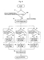
- Fig. 4 is a control flow chart for the low-temperature starting method according to the present invention.
- Low-temperature start in the present invention means a starting operation when the temperature of the reforming catalyst is at or below the minimum temperature at which it can be started by the reforming reaction.
- the entire reformer is heated by feeding an inert gas heated by a heat source such as an electric heater, into a fuel feed line. Consequently, a large amount of inert gas is required, and as shown in Fig. 3A, since the second catalyst layer does not begin to heat until the first catalyst layer is completely heated, it takes a long time before the reformer as a whole reaches the required temperature.
- a heat source such as an electric heater
- the fuel injector 3A is fully closed when the apparatus is started from a low temperature, and while the supply of fuel gas is stopped, air that has been preheated in preheating devices 19a, 19b to a temperature at which the catalyst can be oxidized (about 100 degrees C. or less) is supplied to the upstream side of each catalyst layer 15a, 15b and 15c, in parallel.
- step S1 when a starting signal is activated the catalyst temperature in each stage is compared with a predetermined temperature (for instance, 170 degrees C.) in step S1, and if all the catalyst temperatures are higher, it is judged that a hot start can be activated, so the starting operation proceeds normally to completion; if the measured catalyst temperatures are lower than the predetermined temperature, the preheating device is started (S2). Next, the catalyst temperature in each stage is compared to the predetermined one (S3), and if the measurement for a stage is lower, air is supplied to the stage to make the catalyst generate heat internally (S4), and when the catalyst temperature exceeds the predetermined value, the air supply is shut off (S5). After the catalyst temperatures in all the stages have reached the predetermined temperature, the preheating device is stopped (S6), thus completing the start of the apparatus.
- a predetermined temperature for instance, 170 degrees C.
- the catalyst in each catalyst layer since the catalyst in each catalyst layer generates heat internally at the same time, the whole of the catalyst is heated, the inert gas that was indispensable for conventional systems is no longer required, and as shown in Fig. 3 (b), the catalyst layer in each stage can be warmed simultaneously and in parallel.
- the above-mentioned combustible reforming catalyst 15 is a copper-zinc based reforming catalyst and the oxidation reaction thereof can be expressed by the following equations (1) and (2).
- the amounts of generated heat Q1, Q2 in equations (1) and (2) are about 155 kJ/mol and 348 kJ/mol, respectively, which are comparable to the oxidation heat of hydrogen (about 240 kJ/mol).
- the method of the present invention provides a large amount of internal heat generation by only supplying air preheated to the oxidation activation temperature to the combustible reforming catalyst 15 when it is in a reduced state, so it can be understood that the apparatus can be started (cold start) quickly by using this internally generated heat.
- Figs. 5A and 5B are diagrams describing the starting method when fuel is supplied according to the present invention.
- Fig. 5A shows the method of feeding the fuel gas (methanol + water) and air
- Fig. 5B is a chart showing catalyst temperatures in the reformer.
- the solid lines and chain lines indicate conventional methods and methods according to the present invention, respectively.
- the fuel injector 3a is opened to begin supplying the fuel gas.
- the catalyst temperature quickly increases and temporarily exceeds the withstanding temperature of the catalyst (for instance, 300 degrees C.), which was verified experimentally.
- Equations (3) and (4) are formulae for the reactions (reduction reactions) which are the reverse of the aforementioned oxidation reaction equations (1) and (2), in which the absorbed heat amounts Q1, Q2 are about 155 kJ/mol and 348 kJ/mol, respectively.
- equation (5) shows a hydrogen oxidation reaction with a heat of oxidation Q3 of about 240 kJ/mol. Therefore, when the fuel gas and air are supplied after completing the temperature increase of the combustible reforming catalyst 15, the oxidation reaction of the equation (5) takes place simultaneously with the reduction reactions governed by the equations (3) and (4), and as a result, the catalyst is abnormally overheated.
- the entire catalyst is heated to a temperature at which the combustion reforming reactions can occur, then the flow of air is temporarily stopped by fully closing, for instance, air injectors 21a, 21b, 21c and the supply of fuel gas is started.
- air injectors 21a, 21b, 21c are opened slightly, and air is supplied by controlling the air flows so that the temperatures in the catalysts do not exceed the withstanding temperature of the catalyst.
- Temperature sensors are inserted in each of the catalyst layers 15a, 15b, 15c to detect the temperature of each catalyst layer, and detect the highest temperature after air has been introduced.
- temperature sensors need not be inserted individually into each catalyst layer, but instead, the temperatures of the downstream gasses can be measured, for example, and the temperature of each catalyst is estimated and controlled.
- Fig. 6 shows the results of a test of an embodiment of the present invention.
- warming air and reforming air were supplied in that order from upstream, to a single catalyst.
- the time from the beginning of warming is shown on the abscissa with temperature as the ordinate, the lower chain lines show the temperature of the inlet air, and the 3 upper curves show measured temperatures near the inlet of the catalyst (solid line), an intermediate portion (dotted line) and near the outlet (chain line), respectively.
- the parameter measured near the inlet of the catalyst (solid line) relates to a case using the method of the present invention.
- the catalyst temperature was increased from about 50 degrees C. to 100 degrees C. in about one minute and a half, after that, the supply of air was temporarily stopped, then the flow of reforming air was restarted at a reduced rate, thus the maximum temperature of the catalyst was reduced.
- the starting time for a low-temperature start could be about 3 minutes.
- the present invention provides the following advantages as described above.
- the fuel reforming apparatus and its starting method according to the present invention provide excellent effects such as that a quick start (cold start) is made possible, that the reforming catalyst and the fuel cell can be prevented from being poisoned and that no special equipment or utilities are required and the apparatus can be compact enough to be installed in a electric vehicle.
Landscapes
- Engineering & Computer Science (AREA)
- Chemical & Material Sciences (AREA)
- Chemical Kinetics & Catalysis (AREA)
- Organic Chemistry (AREA)
- Sustainable Development (AREA)
- Mechanical Engineering (AREA)
- Transportation (AREA)
- Power Engineering (AREA)
- Sustainable Energy (AREA)
- Life Sciences & Earth Sciences (AREA)
- Combustion & Propulsion (AREA)
- Health & Medical Sciences (AREA)
- Fluid Mechanics (AREA)
- Physics & Mathematics (AREA)
- Inorganic Chemistry (AREA)
- General Health & Medical Sciences (AREA)
- Hydrogen, Water And Hydrids (AREA)
- Fuel Cell (AREA)
Abstract
Description
Claims (6)
- A fuel reforming apparatus comprising a partial oxidation reformer (14) filled with a combustible reforming catalyst (15) that converts a fuel gas into a reformed gas containing hydrogen by partially oxidizing the fuel gas and using the heat generated thereby, an air feed line (20) for feeding air to the partial oxidation reformer, and a flow controller (22) that controls the flow rate of the air in the air feed line, whereby
when the apparatus is started from a low temperature, while the supply of the fuel gas is stopped, air preheated to a temperature at which the catalyst can be oxidized is fed from the air feed line, in such a manner that the catalyst generates its own heat, and the whole of the catalyst is heated up. - The fuel reforming apparatus specified in Claim 1, wherein
the combustible reforming catalyst (15) comprises a plurality of catalyst layers (15a, 15b, 15c) disposed in series with intervals therebetween, and the air feed line (20) comprises a plurality of branch lines (20a, 20b, 20c) that feed air independently into a point upstream of each of the catalyst layers, whereby
when the apparatus is started from a low temperature, while the supply of the fuel gas is stopped, air preheated to a temperature at which the catalyst can be oxidized is fed in parallel from each branch line, in such a manner that the catalyst generates its own heat and the whole of the catalyst is heated up. - The fuel reforming apparatus specified in Claim 1 or 2, wherein each of the catalyst layers (15a, 15b, 15c) comprises a first catalyst disposed upstream and a second catalyst disposed downstream, and the first catalyst has a withstanding temperature higher than the withstanding temperature of the second catalyst and the second catalyst has a reforming capability higher than the reforming capability of the first catalyst.
- A method of starting a fuel reforming apparatus, wherein
when a partial oxidation reformer (14) filled with a combustible reforming catalyst (15) for reforming a fuel gas containing steam using the heat generated by partially oxidizing the fuel gas is started, while the supply of the fuel gas is stopped, air preheated to a temperature at which the catalyst can be oxidized is fed in, in such a manner that the catalyst generates its own heat, thus the whole of the catalyst is heated up. - The method of starting a fuel reforming apparatus specified in Claim 4, wherein
the combustible reforming catalyst (15) comprises a plurality of catalyst layers (15a, 15b, 15c) disposed in series with intervals therebetween, and
when the apparatus is started from a low temperature, while the supply of the fuel gas is stopped, air preheated in a preheater is fed to a point upstream of each of the catalyst layers in parallel, in such a manner that the catalyst in each catalyst layer generates its own heat, thus the whole of the catalyst is heated up. - The method of starting a fuel reforming apparatus specified in Claim 4 or 5, wherein after the whole of the catalyst is heated to a temperature at which a combustion/reforming reaction can take place, feeding air is temporarily stopped, the supply of the fuel gas is started, next the flow rate of the air is controlled to feed the air in such a manner that the temperatures in the catalyst do not exceed the temperature that the catalyst can withstand.
Applications Claiming Priority (4)
| Application Number | Priority Date | Filing Date | Title |
|---|---|---|---|
| JP2001227472 | 2001-07-27 | ||
| JP2001227472 | 2001-07-27 | ||
| JP2001310874A JP3768137B2 (en) | 2001-07-27 | 2001-10-09 | Fuel reformer and starting method thereof |
| JP2001310874 | 2001-10-09 |
Publications (3)
| Publication Number | Publication Date |
|---|---|
| EP1281668A2 true EP1281668A2 (en) | 2003-02-05 |
| EP1281668A3 EP1281668A3 (en) | 2004-02-04 |
| EP1281668B1 EP1281668B1 (en) | 2006-10-04 |
Family
ID=26619415
Family Applications (1)
| Application Number | Title | Priority Date | Filing Date |
|---|---|---|---|
| EP02016374A Expired - Lifetime EP1281668B1 (en) | 2001-07-27 | 2002-07-25 | Fuel reforming apparatus and the method of starting it |
Country Status (4)
| Country | Link |
|---|---|
| US (1) | US6977002B2 (en) |
| EP (1) | EP1281668B1 (en) |
| JP (1) | JP3768137B2 (en) |
| DE (1) | DE60215086T2 (en) |
Cited By (3)
| Publication number | Priority date | Publication date | Assignee | Title |
|---|---|---|---|---|
| WO2006009495A1 (en) * | 2004-07-19 | 2006-01-26 | Ab Volvo | Method of starting a fuel reforming process and a fuel reforming system |
| WO2006088234A1 (en) * | 2005-02-16 | 2006-08-24 | Toyota Jidosha Kabushiki Kaisha | Fuel gas processing apparatus |
| CN111152688A (en) * | 2019-12-27 | 2020-05-15 | 中国第一汽车股份有限公司 | Control method for thermal management system of fuel cell automobile |
Families Citing this family (22)
| Publication number | Priority date | Publication date | Assignee | Title |
|---|---|---|---|---|
| US7101175B2 (en) * | 2003-04-04 | 2006-09-05 | Texaco Inc. | Anode tailgas oxidizer |
| WO2005001960A2 (en) | 2003-06-27 | 2005-01-06 | Ultracell Corporation | Fuel preheat in fuel cells and portable electronics |
| US8318368B2 (en) | 2003-06-27 | 2012-11-27 | UltraCell, L.L.C. | Portable systems for engine block |
| US7666539B2 (en) * | 2003-06-27 | 2010-02-23 | Ultracell Corporation | Heat efficient portable fuel cell systems |
| JP4709507B2 (en) * | 2003-07-14 | 2011-06-22 | 株式会社ケー・イー・エム | Reformer |
| EP1498388A1 (en) * | 2003-07-14 | 2005-01-19 | Toyo Engineering Corporation | Reformer |
| WO2005090230A1 (en) * | 2004-03-12 | 2005-09-29 | Hyradix, Inc. | Hydrogen generator apparatus and start-up processes |
| EP1786725A2 (en) * | 2004-06-11 | 2007-05-23 | Nuvera Fuel Cells, Inc. | Fuel fired hydrogen generator |
| JP2008528430A (en) * | 2005-01-28 | 2008-07-31 | ミレニアム セル インコーポレイテッド | System and method for controlling hydrogen generation |
| JP4656985B2 (en) * | 2005-04-05 | 2011-03-23 | トヨタ自動車株式会社 | Hydrogen generator and fuel cell system |
| JP2007039322A (en) * | 2005-07-01 | 2007-02-15 | Mitsubishi Heavy Ind Ltd | Reforming method and reforming apparatus |
| US7659019B2 (en) | 2005-09-16 | 2010-02-09 | Idatech, Llc | Thermally primed hydrogen-producing fuel cell system |
| JP4887048B2 (en) * | 2006-01-30 | 2012-02-29 | アイシン精機株式会社 | Fuel cell starting method and fuel cell system |
| JP5160796B2 (en) * | 2007-02-13 | 2013-03-13 | Jx日鉱日石エネルギー株式会社 | FUEL CELL SYSTEM AND METHOD FOR OPERATING FUEL CELL SYSTEM |
| KR100814858B1 (en) | 2007-02-21 | 2008-03-20 | 삼성에스디아이 주식회사 | Operation method of heat source unit for fuel cell reforming unit, reforming unit applying the same, and fuel cell system applying the same |
| JP5441001B2 (en) * | 2009-05-28 | 2014-03-12 | Toto株式会社 | Solid oxide fuel cell |
| EP3378683A1 (en) | 2010-02-05 | 2018-09-26 | Fox Factory, Inc. | Method and apparatus for suspension adjustment |
| US8591844B1 (en) | 2012-05-17 | 2013-11-26 | Fluor Technologies Corporation | Start up catalyst heating |
| JP5806979B2 (en) * | 2012-06-08 | 2015-11-10 | 株式会社豊田自動織機 | Reformer |
| CN109873179B (en) * | 2017-12-04 | 2022-03-08 | 中国科学院大连化学物理研究所 | A kind of fuel cell system and low temperature quick start method |
| KR20200002058A (en) * | 2018-06-29 | 2020-01-08 | 주식회사 경동나비엔 | Reformer and fuel cell system having the same |
| US11316180B2 (en) | 2020-05-21 | 2022-04-26 | H2 Powertech, Llc | Hydrogen-producing fuel cell systems and methods of operating hydrogen-producing fuel cell systems for backup power operations |
Family Cites Families (8)
| Publication number | Priority date | Publication date | Assignee | Title |
|---|---|---|---|---|
| US4033133A (en) * | 1976-03-22 | 1977-07-05 | California Institute Of Technology | Start up system for hydrogen generator used with an internal combustion engine |
| JPS6350302A (en) | 1986-08-14 | 1988-03-03 | Fuji Electric Co Ltd | Methanol reformer |
| JPH06256001A (en) | 1993-03-02 | 1994-09-13 | Idemitsu Kosan Co Ltd | Production of hydrogen-containing gas |
| JPH06279001A (en) | 1993-03-26 | 1994-10-04 | Idemitsu Kosan Co Ltd | Method for producing hydrogen-containing gas |
| JPH08157201A (en) | 1994-12-05 | 1996-06-18 | Toyota Motor Corp | Fuel reformer |
| ATE199366T1 (en) | 1996-11-15 | 2001-03-15 | Haldor Topsoe As | METHOD FOR THE CATALYTIC PARTIAL OXIDATION OF A HYDROCARBON |
| US6472092B1 (en) * | 1998-08-12 | 2002-10-29 | Honda Giken Kogyo Kabushiki Kaisha | Fuel-reforming apparatus comprising a plate-shaped reforming catalyst |
| JP2001295707A (en) * | 1999-06-03 | 2001-10-26 | Toyota Motor Corp | Fuel reformer for vehicle installation |
-
2001
- 2001-10-09 JP JP2001310874A patent/JP3768137B2/en not_active Expired - Fee Related
-
2002
- 2002-07-19 US US10/197,862 patent/US6977002B2/en not_active Expired - Fee Related
- 2002-07-25 EP EP02016374A patent/EP1281668B1/en not_active Expired - Lifetime
- 2002-07-25 DE DE60215086T patent/DE60215086T2/en not_active Expired - Fee Related
Cited By (4)
| Publication number | Priority date | Publication date | Assignee | Title |
|---|---|---|---|---|
| WO2006009495A1 (en) * | 2004-07-19 | 2006-01-26 | Ab Volvo | Method of starting a fuel reforming process and a fuel reforming system |
| WO2006088234A1 (en) * | 2005-02-16 | 2006-08-24 | Toyota Jidosha Kabushiki Kaisha | Fuel gas processing apparatus |
| CN111152688A (en) * | 2019-12-27 | 2020-05-15 | 中国第一汽车股份有限公司 | Control method for thermal management system of fuel cell automobile |
| CN111152688B (en) * | 2019-12-27 | 2021-04-20 | 中国第一汽车股份有限公司 | Control method for thermal management system of fuel cell automobile |
Also Published As
| Publication number | Publication date |
|---|---|
| EP1281668A3 (en) | 2004-02-04 |
| JP3768137B2 (en) | 2006-04-19 |
| DE60215086T2 (en) | 2007-01-11 |
| DE60215086D1 (en) | 2006-11-16 |
| EP1281668B1 (en) | 2006-10-04 |
| US6977002B2 (en) | 2005-12-20 |
| JP2003104706A (en) | 2003-04-09 |
| US20030019156A1 (en) | 2003-01-30 |
Similar Documents
| Publication | Publication Date | Title |
|---|---|---|
| US6977002B2 (en) | Fuel reforming apparatus and the method of starting it | |
| US6790548B2 (en) | Staged venting of fuel cell system during rapid shutdown | |
| US6294149B1 (en) | Process for operating a water vapor reforming system, a reforming system operable thereby and a fuel cell system operating process | |
| EP1067614B1 (en) | Fuel cell system logic for differentiating between rapid and normal shutdown commands | |
| US6521204B1 (en) | Method for operating a combination partial oxidation and steam reforming fuel processor | |
| JP3739635B2 (en) | Fuel cell stack monitoring and system control | |
| US6086839A (en) | System and process for the water vapor reforming of a hydrocarbon | |
| JP5292389B2 (en) | Hydrogen system and method for starting hydrogen system | |
| US6436561B1 (en) | Methanol tailgas combustor control method | |
| US6485853B1 (en) | Fuel cell system having thermally integrated, isothermal co-cleansing subsystem | |
| EP1231183B1 (en) | Fuel reformer system | |
| US6413662B1 (en) | Fuel cell system shutdown with anode pressure control | |
| JP2009099264A (en) | Solid oxide fuel cell power generation system and startup method thereof | |
| JP2003300704A (en) | Fuel reforming system and fuel cell system | |
| US20050227129A1 (en) | Fuel cell power plant warm up | |
| US7465325B2 (en) | Fuel reforming system and warmup method thereof | |
| EP1386882A1 (en) | Hydrogen formation apparatus | |
| JP2001093550A (en) | Polymer electrolyte fuel cell power generator and operation method thereof | |
| JP2003104707A (en) | Fuel reformer and its stopping method | |
| EP1329417A1 (en) | Hydrogen forming device | |
| JP5102938B2 (en) | Fuel cell power generation system and starting method thereof | |
| US7547333B2 (en) | Fuel reforming system | |
| US20090246568A1 (en) | System for the generation of electric power on-board a motor vehicle which is equipped with a fuel cell and associated method | |
| JP3620486B2 (en) | Fuel cell system | |
| JP2005170741A (en) | Fuel reforming system |
Legal Events
| Date | Code | Title | Description |
|---|---|---|---|
| PUAI | Public reference made under article 153(3) epc to a published international application that has entered the european phase |
Free format text: ORIGINAL CODE: 0009012 |
|
| AK | Designated contracting states |
Designated state(s): AT BE BG CH CY CZ DE DK EE ES FI FR GB GR IE IT LI LU MC NL PT SE SK TR |
|
| AX | Request for extension of the european patent |
Extension state: AL LT LV MK RO SI |
|
| PUAL | Search report despatched |
Free format text: ORIGINAL CODE: 0009013 |
|
| AK | Designated contracting states |
Kind code of ref document: A3 Designated state(s): AT BE BG CH CY CZ DE DK EE ES FI FR GB GR IE IT LI LU MC NL PT SE SK TR |
|
| AX | Request for extension of the european patent |
Extension state: AL LT LV MK RO SI |
|
| 17P | Request for examination filed |
Effective date: 20040225 |
|
| AKX | Designation fees paid |
Designated state(s): DE |
|
| 17Q | First examination report despatched |
Effective date: 20040927 |
|
| GRAP | Despatch of communication of intention to grant a patent |
Free format text: ORIGINAL CODE: EPIDOSNIGR1 |
|
| GRAS | Grant fee paid |
Free format text: ORIGINAL CODE: EPIDOSNIGR3 |
|
| GRAA | (expected) grant |
Free format text: ORIGINAL CODE: 0009210 |
|
| AK | Designated contracting states |
Kind code of ref document: B1 Designated state(s): DE |
|
| REF | Corresponds to: |
Ref document number: 60215086 Country of ref document: DE Date of ref document: 20061116 Kind code of ref document: P |
|
| PLBE | No opposition filed within time limit |
Free format text: ORIGINAL CODE: 0009261 |
|
| STAA | Information on the status of an ep patent application or granted ep patent |
Free format text: STATUS: NO OPPOSITION FILED WITHIN TIME LIMIT |
|
| 26N | No opposition filed |
Effective date: 20070705 |
|
| PGFP | Annual fee paid to national office [announced via postgrant information from national office to epo] |
Ref country code: DE Payment date: 20090723 Year of fee payment: 8 |
|
| PG25 | Lapsed in a contracting state [announced via postgrant information from national office to epo] |
Ref country code: DE Free format text: LAPSE BECAUSE OF NON-PAYMENT OF DUE FEES Effective date: 20110201 |
|
| REG | Reference to a national code |
Ref country code: DE Ref legal event code: R119 Ref document number: 60215086 Country of ref document: DE Effective date: 20110201 |