EP1281641A1 - Drive system for modular link conveyor belts - Google Patents
Drive system for modular link conveyor belts Download PDFInfo
- Publication number
- EP1281641A1 EP1281641A1 EP02077663A EP02077663A EP1281641A1 EP 1281641 A1 EP1281641 A1 EP 1281641A1 EP 02077663 A EP02077663 A EP 02077663A EP 02077663 A EP02077663 A EP 02077663A EP 1281641 A1 EP1281641 A1 EP 1281641A1
- Authority
- EP
- European Patent Office
- Prior art keywords
- band
- conveyor
- teeth
- drive system
- toothed wheel
- Prior art date
- Legal status (The legal status is an assumption and is not a legal conclusion. Google has not performed a legal analysis and makes no representation as to the accuracy of the status listed.)
- Granted
Links
Images


Classifications
-
- B—PERFORMING OPERATIONS; TRANSPORTING
- B65—CONVEYING; PACKING; STORING; HANDLING THIN OR FILAMENTARY MATERIAL
- B65G—TRANSPORT OR STORAGE DEVICES, e.g. CONVEYORS FOR LOADING OR TIPPING, SHOP CONVEYOR SYSTEMS OR PNEUMATIC TUBE CONVEYORS
- B65G21/00—Supporting or protective framework or housings for endless load-carriers or traction elements of belt or chain conveyors
- B65G21/16—Supporting or protective framework or housings for endless load-carriers or traction elements of belt or chain conveyors for conveyors having endless load-carriers movable in curved paths
- B65G21/18—Supporting or protective framework or housings for endless load-carriers or traction elements of belt or chain conveyors for conveyors having endless load-carriers movable in curved paths in three-dimensionally curved paths
-
- B—PERFORMING OPERATIONS; TRANSPORTING
- B65—CONVEYING; PACKING; STORING; HANDLING THIN OR FILAMENTARY MATERIAL
- B65G—TRANSPORT OR STORAGE DEVICES, e.g. CONVEYORS FOR LOADING OR TIPPING, SHOP CONVEYOR SYSTEMS OR PNEUMATIC TUBE CONVEYORS
- B65G23/00—Driving gear for endless conveyors; Belt- or chain-tensioning arrangements
- B65G23/02—Belt- or chain-engaging elements
- B65G23/04—Drums, rollers, or wheels
- B65G23/06—Drums, rollers, or wheels with projections engaging abutments on belts or chains, e.g. sprocket wheels
-
- B—PERFORMING OPERATIONS; TRANSPORTING
- B65—CONVEYING; PACKING; STORING; HANDLING THIN OR FILAMENTARY MATERIAL
- B65G—TRANSPORT OR STORAGE DEVICES, e.g. CONVEYORS FOR LOADING OR TIPPING, SHOP CONVEYOR SYSTEMS OR PNEUMATIC TUBE CONVEYORS
- B65G17/00—Conveyors having an endless traction element, e.g. a chain, transmitting movement to a continuous or substantially-continuous load-carrying surface or to a series of individual load-carriers; Endless-chain conveyors in which the chains form the load-carrying surface
- B65G17/06—Conveyors having an endless traction element, e.g. a chain, transmitting movement to a continuous or substantially-continuous load-carrying surface or to a series of individual load-carriers; Endless-chain conveyors in which the chains form the load-carrying surface having a load-carrying surface formed by a series of interconnected, e.g. longitudinal, links, plates, or platforms
- B65G17/063—Conveyors having an endless traction element, e.g. a chain, transmitting movement to a continuous or substantially-continuous load-carrying surface or to a series of individual load-carriers; Endless-chain conveyors in which the chains form the load-carrying surface having a load-carrying surface formed by a series of interconnected, e.g. longitudinal, links, plates, or platforms the load carrying surface being formed by profiles, rods, bars, rollers or the like attached to more than one traction element
- B65G17/064—Conveyors having an endless traction element, e.g. a chain, transmitting movement to a continuous or substantially-continuous load-carrying surface or to a series of individual load-carriers; Endless-chain conveyors in which the chains form the load-carrying surface having a load-carrying surface formed by a series of interconnected, e.g. longitudinal, links, plates, or platforms the load carrying surface being formed by profiles, rods, bars, rollers or the like attached to more than one traction element the profiles, rods, bars, rollers or the like being interconnected by a mesh or grid-like structure
-
- B—PERFORMING OPERATIONS; TRANSPORTING
- B65—CONVEYING; PACKING; STORING; HANDLING THIN OR FILAMENTARY MATERIAL
- B65G—TRANSPORT OR STORAGE DEVICES, e.g. CONVEYORS FOR LOADING OR TIPPING, SHOP CONVEYOR SYSTEMS OR PNEUMATIC TUBE CONVEYORS
- B65G17/00—Conveyors having an endless traction element, e.g. a chain, transmitting movement to a continuous or substantially-continuous load-carrying surface or to a series of individual load-carriers; Endless-chain conveyors in which the chains form the load-carrying surface
- B65G17/06—Conveyors having an endless traction element, e.g. a chain, transmitting movement to a continuous or substantially-continuous load-carrying surface or to a series of individual load-carriers; Endless-chain conveyors in which the chains form the load-carrying surface having a load-carrying surface formed by a series of interconnected, e.g. longitudinal, links, plates, or platforms
- B65G17/067—Conveyors having an endless traction element, e.g. a chain, transmitting movement to a continuous or substantially-continuous load-carrying surface or to a series of individual load-carriers; Endless-chain conveyors in which the chains form the load-carrying surface having a load-carrying surface formed by a series of interconnected, e.g. longitudinal, links, plates, or platforms the load carrying surface being formed by plates or platforms attached to more than one traction element
Definitions
- This invention relates to an improved drive and guide system for conveyor bands for packaged or non-packaged food or other products, a typical use of which is in cooling, deep freezing, leavening, pasteurization, drying, purification or air conditioning plants.
- a typical shape of such bands is a vertical cylindrical helix, with usually straight product arrival and departure portions, it offering high loading capacity and relatively small overall dimensions.
- the overall dimension in the vertical direction can be limited by using a drive system comprising, for each individual turn of said helix, at least one motorized sprocket of vertical axis positioned to the side of the band and engaging a chain associated with the facing side of the conveyor band or belt.
- a chain widely used for this purpose is one in which the links consist of rings obtained by shaping pieces of round bar and welding them, these rings then being welded to the transverse elements of the band, such as slats or rods, these latter possibly being combined with a mesh.
- the chains of said known translating bands are coupled to respective profiled guide and slide bars which are carried by the longitudinal band support members, and are usually constructed of a synthetic food-quality material, such as polyethylene or polyzene.
- Such translating bands have proved unsatisfactory for the following reasons.
- Said coupling imprecision means that the translational movement of the band is not perfectly synchronous with the rotational movement of the sprocket, i.e. between the two there are small idle movements and hence mutual impact. Essentially, even if the conveyor speed is constant overall, it presents small discontinuities as a result of which the conveyor is subjected to vibration.
- said impact generates annoying noise, causes more rapid wear, and can result in breakage or yielding by fatigue, especially if particularly high temperature gradients are present as in the case of refrigeration or deep freezing plants.
- Said vibration can also be inconvenient in the presence of delicate and/or poorly stable products or containers.
- This vibration also generates noise which adds to the impact noise and the noise due to the sliding of the band along the profiled guide and slide bars, with obvious gradual increase in wear.
- Said radial thrust generates, by friction on the guide, a parasite moment perpendicular to the conveying plane which has to be balanced together with said radial thrust.
- the main object of this invention is to provide means able to overcome, or at least strongly mitigate, the aforesaid problem.
- Anther object of the invention is to attain said objective within the context of a simple, rational, reliable and durable construction.
- the drive member and the driven member of the system consist respectively of a toothed wheel, the flanks of the teeth of which have a profile which is the involute of a circle, and a double articulated chain, the links of which are individually provided with a tooth having straight flanks (tooth of trapezoidal profile) with its profile compatible with that of the toothed wheel.
- the invention also comprises two modular elements provided at their ends with appendices, the branches of which face the lower and outer faces of the respective guides, in order to balance said parasite moment and radial thrust.
- the combination of the said means provides a linkage of rack-and-pinion type in which the rack is flexible and always presents a curvature which is always negligible relative to the pitch circle radius of the pinion, the engagement of which is known to be delicate, precise and with extremely low friction.
- Said precise engagement means that the drive member and driven member operate in synchronism, so that the band translates at virtually constant continuous speed, i.e. with the absence of variations, and hence virtually without impact, vibration and noise. This absence of vibration is particularly convenient when delicate and/or poorly stable products or containers are present.
- Said figures show two longitudinal profiled support and slide members 1 for the band which in cross-section are shaped as an asymmetrical channel the longitudinal mouth of which faces outwards from the respective side of the translating band or belt.
- the walls 11, 22 of said channel profile are of different width, that wall 11 of smaller width being positioned above and horizontal, whereas that wall 22 of greater width is positioned below and is downwardly inclined with its free edge connected to a vertical flange 99 for fixing to the conveyor support structure.
- Respective guides 2 are coupled to said upper walls 11 of said longitudinal members 1 along their entire length.
- the longitudinal members 1 are preferably constructed of metal, typically stainless steel, the guides 2 being of plastic, typically polyethylene or teflon of food-quality type.
- the band comprises two opposing chains, typically of metal, the links of which consist of a step-shaped plate which at one end presents a hole and at the other end a slot.
- the marginal edges of the band i.e. the two opposing longitudinal strips positioned in correspondence with the guides 2, in each case consist of two alignments of modular elements 8.
- At least said marginal modular elements 8 are formed of a synthetic material, such as acetal resin, i.e. a material having virtually the same nature as the constituent material of the guides 2.
- said marginal modular elements 8 act as slide shoes for the band, such shoes providing two advantages.
- the first is that the friction between the modular elements 8 and the guides 2 is much less than that present between the metal and plastic of the aforesaid known art, and normally less than one half, with evidently less power consumption.
- the second derives from the fact that the almost identical nature of the constituent materials of the modular elements 8 and guides 2 prevents these latter becoming blackened.
- the said marginal modular elements 8 are each provided with band retention means in the form of two right-angled descending appendices 6 the branches of which face the lower and outer faces of the respective guide 2.
- each individual block 5 and the respective link of the chain 10 means are provided to prevent untimely rotation between the two (see Figure 3), for example these can be made integral therewith.
- said antirotational means consist of a recess 55 provided on the outside of the link, and in which the base of the block 5 engages.
- the said base presents, above and below, two band retention ribs 4 which engage respective guide profiles 50 (see Figure 2) carried by the conveyor structure.
- Said profiles 50 cooperate with said marginal elements 8 and with said appendices 6 to counteract the forces acting on the band, of which mention has been made in the introduction.
- the outer part 3 of said block 5 is shaped as a trapezoidal tooth, i.e. a tooth of the type used on racks, its flanks also involving those portions of the block 5 lying between said two ribs 4, see Figure 3.
- the belt can be driven by two opposing toothed wheels 33, and that the band can undergo curves both within and perpendicular to its conveying plane.
- the blocks 5 are preferably removably mounted on the links of the chain 10 to enable damaged teeth 3 to be replaced.
Abstract
Description
- This invention relates to an improved drive and guide system for conveyor bands for packaged or non-packaged food or other products, a typical use of which is in cooling, deep freezing, leavening, pasteurization, drying, purification or air conditioning plants.
- In such treatment plants, particularly lengthy translating bands are used, able to follow curves both within and perpendicular to the conveying plane.
- A typical shape of such bands is a vertical cylindrical helix, with usually straight product arrival and departure portions, it offering high loading capacity and relatively small overall dimensions.
- In particular, the overall dimension in the vertical direction can be limited by using a drive system comprising, for each individual turn of said helix, at least one motorized sprocket of vertical axis positioned to the side of the band and engaging a chain associated with the facing side of the conveyor band or belt.
- A chain widely used for this purpose is one in which the links consist of rings obtained by shaping pieces of round bar and welding them, these rings then being welded to the transverse elements of the band, such as slats or rods, these latter possibly being combined with a mesh.
- Other known chains comprise links obtained from metal plate by blanking and drawing operations, and welded to said transverse elements of the band, possibly combined with a mesh.
- The chains of said known translating bands are coupled to respective profiled guide and slide bars which are carried by the longitudinal band support members, and are usually constructed of a synthetic food-quality material, such as polyethylene or polyzene. Such translating bands have proved unsatisfactory for the following reasons.
- Firstly the mutual coupling or engagement between the sprocket and chain is of relatively poor precision because of said welding operations, as a result of which the chain rings undergo both dimensional and shape variations which are virtually uncontrollable and hence normally different from one ring to another.
- Said coupling imprecision means that the translational movement of the band is not perfectly synchronous with the rotational movement of the sprocket, i.e. between the two there are small idle movements and hence mutual impact. Essentially, even if the conveyor speed is constant overall, it presents small discontinuities as a result of which the conveyor is subjected to vibration.
- In particular, said impact generates annoying noise, causes more rapid wear, and can result in breakage or yielding by fatigue, especially if particularly high temperature gradients are present as in the case of refrigeration or deep freezing plants.
- Said vibration can also be inconvenient in the presence of delicate and/or poorly stable products or containers. This vibration also generates noise which adds to the impact noise and the noise due to the sliding of the band along the profiled guide and slide bars, with obvious gradual increase in wear.
- Moreover between the typically metal known chains and the respective profiled guide and slide bars, typically of food-quality plastic, there is consistent rubbing due to the weight of the band and the relative conveyed load, to the action of the sprocket on the chain, and to the possible tension of the curved band within the conveying plane.
- Said rubbing between said different materials gives rise to consistent variations in the original colour of the profiled guide bars, usually blackening which deteriorates their appearance, to the annoyance of the user.
- Moreover, because of the different nature of said metal and synthetic materials the mutual friction is relatively high, with consequent high power consumption.
- Finally when the band is under tension during curving in the conveying plane a radial thrust is induced, directed towards the centre of the curve.
- Said radial thrust generates, by friction on the guide, a parasite moment perpendicular to the conveying plane which has to be balanced together with said radial thrust.
- The main object of this invention is to provide means able to overcome, or at least strongly mitigate, the aforesaid problem. Anther object of the invention is to attain said objective within the context of a simple, rational, reliable and durable construction.
- Said objects are attained by a drive system presenting the characteristics indicated in the claims.
- In attaining said objects, according to the invention the drive member and the driven member of the system consist respectively of a toothed wheel, the flanks of the teeth of which have a profile which is the involute of a circle, and a double articulated chain, the links of which are individually provided with a tooth having straight flanks (tooth of trapezoidal profile) with its profile compatible with that of the toothed wheel.
- The invention also comprises two modular elements provided at their ends with appendices, the branches of which face the lower and outer faces of the respective guides, in order to balance said parasite moment and radial thrust.
- All the objects of the invention are attained by virtue of the aforedefined solution.
- In this respect, the combination of the said means provides a linkage of rack-and-pinion type in which the rack is flexible and always presents a curvature which is always negligible relative to the pitch circle radius of the pinion, the engagement of which is known to be delicate, precise and with extremely low friction.
- Said precise engagement means that the drive member and driven member operate in synchronism, so that the band translates at virtually constant continuous speed, i.e. with the absence of variations, and hence virtually without impact, vibration and noise. This absence of vibration is particularly convenient when delicate and/or poorly stable products or containers are present.
- These and further advantages, together with the constructional characteristics and merits of the proposed system and of those of a conveyor equipped with it will be apparent from the ensuing detailed description given with reference to the figures of the accompanying drawings, in which:
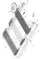
- Figure 1 is a perspective view of a portion of a translating band provided with a drive system according to the invention.
- Figure 2 shows part of the view obtained in the direction II of Figure 1, on an enlarged scale.
- Figure 3 shows a detail of Figure 1, on a considerably enlarged scale.
-
- Said figures show two longitudinal profiled support and
slide members 1 for the band which in cross-section are shaped as an asymmetrical channel the longitudinal mouth of which faces outwards from the respective side of the translating band or belt. Specifically, thewalls wall 11 of smaller width being positioned above and horizontal, whereas thatwall 22 of greater width is positioned below and is downwardly inclined with its free edge connected to avertical flange 99 for fixing to the conveyor support structure. - The provision of such longitudinal members open along their entire length and having their lower wall inclined downwards has the advantage of enabling them to be easily and completely cleaned and sanitized, and moreover they do not present closed or difficultly accessible regions where dirt could accumulate and/or cleaning/sanitizing liquids and products could stagnate.
-
Respective guides 2 are coupled to saidupper walls 11 of saidlongitudinal members 1 along their entire length. - The
longitudinal members 1 are preferably constructed of metal, typically stainless steel, theguides 2 being of plastic, typically polyethylene or teflon of food-quality type. - The band comprises two opposing chains, typically of metal, the links of which consist of a step-shaped plate which at one end presents a hole and at the other end a slot.
- Through said apertures are inserted the opposite ends of a plurality of identical
transverse metal rods 9 which, either alone or in combination with ametal mesh 7 or a plurality of profiledmodular elements 8, form the conveying surface of the band (see Figure 1). According to the invention, the marginal edges of the band, i.e. the two opposing longitudinal strips positioned in correspondence with theguides 2, in each case consist of two alignments ofmodular elements 8. - According to the invention, at least said marginal
modular elements 8 are formed of a synthetic material, such as acetal resin, i.e. a material having virtually the same nature as the constituent material of theguides 2. - In this manner said marginal
modular elements 8 act as slide shoes for the band, such shoes providing two advantages. - The first is that the friction between the
modular elements 8 and theguides 2 is much less than that present between the metal and plastic of the aforesaid known art, and normally less than one half, with evidently less power consumption. - The second derives from the fact that the almost identical nature of the constituent materials of the
modular elements 8 andguides 2 prevents these latter becoming blackened. - The said marginal
modular elements 8 are each provided with band retention means in the form of two right-angled descendingappendices 6 the branches of which face the lower and outer faces of therespective guide 2. - The opposite ends of the
rods 9 project beyond thechains 10, where they carry, fixed thereto, respective profiledblocks 5, which can be of metal or plastic, provided with a through hole 15 (Figures 1 and 2). Said fixing can be done by any method, for example by cold forced fitting, by ribbing, by crimping the heads of therods 9, by threaded means or by brazing. - In particular, between each
individual block 5 and the respective link of thechain 10, means are provided to prevent untimely rotation between the two (see Figure 3), for example these can be made integral therewith. - In the illustrated example, said antirotational means consist of a
recess 55 provided on the outside of the link, and in which the base of theblock 5 engages. - The said base presents, above and below, two
band retention ribs 4 which engage respective guide profiles 50 (see Figure 2) carried by the conveyor structure. - Said
profiles 50 cooperate with saidmarginal elements 8 and with saidappendices 6 to counteract the forces acting on the band, of which mention has been made in the introduction. - Moreover, the
outer part 3 of saidblock 5 is shaped as a trapezoidal tooth, i.e. a tooth of the type used on racks, its flanks also involving those portions of theblock 5 lying between said tworibs 4, see Figure 3. - With said
tooth 3 there engages the circular involute toothing of a motorizedtoothed wheel 33 of vertical axis positioned to the side of the conveyor belt or band, its pressing angle conforming to the characteristics of the conveyor. - The merits and advantages of the invention, together with its operation and use. are apparent from the aforegoing and from an examination of the accompanying figures.
- It is sufficient to state that the belt can be driven by two opposing
toothed wheels 33, and that the band can undergo curves both within and perpendicular to its conveying plane. - The
blocks 5 are preferably removably mounted on the links of thechain 10 to enable damagedteeth 3 to be replaced.
Claims (9)
- A drive system typically for band conveyors, comprising at least one motorized gear arranged to engage a chain (10) associated with the side of the conveyor, characterised in that said at least one gear (33) consists of a toothed wheel having its axis perpendicular to the plane of the conveyor, and circular involute profiles that engage conjugate straight-flanked teeth (3) associated with the chain structure.
- A system as claimed in claim 1, characterised in that said teeth are secured to the chain structure by means which are removable to facilitate their replacement as a result of wear.
- A system as claimed in claim 1, characterised in that said teeth are carried by the chain structure by way of interposed means for preventing their untimely relative movement.
- A system as claimed in claim 3, characterised in that said means are in the form of a prismatic coupling.
- A system as claimed in claim 1, characterised in that said conjugate teeth present a trapezoidal profile when viewed in a direction perpendicular to the plane of engagement with the toothed wheel.
- A system as claimed in claim 1, characterised in that said conjugate teeth are each provided, in correspondence with their base on one and the other side of the plane of engagement with the toothed wheel, with two opposing ribs perpendicular to the band.
- A band conveyor comprising a motorized translating band the two opposing marginal longitudinal edges of which rest on full-length guide and slide profiles carried by respective longitudinal members, characterised by being provided with a drive system in accordance with claims from 1 to 6.
- A conveyor as claimed in claim 7, characterised in that said opposing marginal longitudinal edges of said band are in the form of slide shoes constructed of a material similar to that of said guide profiles, such as to minimize the friction between them.
- A conveyor as claimed in claim 7, characterised in that said longitudinal members have a cross-section in the form of an asymmetric channel, the mouth of which faces outwards from the band, their lower wall being inclined downwards.
Applications Claiming Priority (2)
| Application Number | Priority Date | Filing Date | Title |
|---|---|---|---|
| IT2001RE000030U ITRE20010030U1 (en) | 2001-08-03 | 2001-08-03 | TOWING SYSTEM TYPICALLY FOR CONVEYOR BELTS AND CARPETS. |
| ITRE20000030U | 2001-08-03 |
Publications (2)
| Publication Number | Publication Date |
|---|---|
| EP1281641A1 true EP1281641A1 (en) | 2003-02-05 |
| EP1281641B1 EP1281641B1 (en) | 2005-05-25 |
Family
ID=11454075
Family Applications (1)
| Application Number | Title | Priority Date | Filing Date |
|---|---|---|---|
| EP02077663A Expired - Lifetime EP1281641B1 (en) | 2001-08-03 | 2002-07-04 | Drive system for modular link conveyor belts |
Country Status (5)
| Country | Link |
|---|---|
| EP (1) | EP1281641B1 (en) |
| AT (1) | ATE296252T1 (en) |
| DE (1) | DE60204265T2 (en) |
| ES (1) | ES2240648T3 (en) |
| IT (1) | ITRE20010030U1 (en) |
Cited By (10)
| Publication number | Priority date | Publication date | Assignee | Title |
|---|---|---|---|---|
| NL2001010C2 (en) * | 2007-11-16 | 2009-05-19 | Kaak Johan H B | Spiral conveyor. |
| ITVE20090018A1 (en) * | 2009-03-20 | 2010-09-21 | Tecno Pool Spa | CONTINUOUS CONVEYOR WITH TRANSVERSAL BARS, PARTICULARLY FOR THE FOOD INDUSTRY.- |
| WO2012009222A1 (en) * | 2010-07-12 | 2012-01-19 | Laitram, L.L.C. | Positive-drive spiral conveyor and belt |
| US8181771B2 (en) | 2010-07-12 | 2012-05-22 | Laitram, L.L.C. | Positive-drive spiral conveyor |
| ITPD20120267A1 (en) * | 2012-09-14 | 2014-03-15 | Alit S R L | PERFECTED JERSEY FOR SIDE CHAIN FOR CONVEYOR BELTS |
| US9079719B2 (en) | 2013-09-30 | 2015-07-14 | Laitram, L.L.C. | Positive-drive spiral conveyor with overlapping cage-bar caps |
| US9394109B2 (en) | 2012-03-21 | 2016-07-19 | Laitram, L.L.C. | Positive-drive spiral conveyor |
| EP3257793A1 (en) | 2016-06-13 | 2017-12-20 | Frans Bakker Beheer B.V. | Conveyor belt |
| IT201900013509A1 (en) * | 2019-07-31 | 2021-01-31 | Gea Imaforni S P A | CONVEYOR BELT, TRANSPORT APPARATUS AND OVEN FOR COOKING PRODUCTS, IN PARTICULAR FOOD |
| SE2250321A1 (en) * | 2022-03-14 | 2023-09-15 | Valmet Oy | A beam for a chain conveyor |
Citations (2)
| Publication number | Priority date | Publication date | Assignee | Title |
|---|---|---|---|---|
| GB1090630A (en) * | 1965-02-15 | 1967-11-08 | Ashworth Bros Inc | Conveyor system |
| GB2056400A (en) * | 1979-08-16 | 1981-03-18 | Plm Ab | Driving arrangement for closed loop conveying apparatus |
-
2001
- 2001-08-03 IT IT2001RE000030U patent/ITRE20010030U1/en unknown
-
2002
- 2002-07-04 EP EP02077663A patent/EP1281641B1/en not_active Expired - Lifetime
- 2002-07-04 ES ES02077663T patent/ES2240648T3/en not_active Expired - Lifetime
- 2002-07-04 AT AT02077663T patent/ATE296252T1/en not_active IP Right Cessation
- 2002-07-04 DE DE60204265T patent/DE60204265T2/en not_active Expired - Lifetime
Patent Citations (2)
| Publication number | Priority date | Publication date | Assignee | Title |
|---|---|---|---|---|
| GB1090630A (en) * | 1965-02-15 | 1967-11-08 | Ashworth Bros Inc | Conveyor system |
| GB2056400A (en) * | 1979-08-16 | 1981-03-18 | Plm Ab | Driving arrangement for closed loop conveying apparatus |
Cited By (27)
| Publication number | Priority date | Publication date | Assignee | Title |
|---|---|---|---|---|
| NL2001010C2 (en) * | 2007-11-16 | 2009-05-19 | Kaak Johan H B | Spiral conveyor. |
| WO2009064184A1 (en) * | 2007-11-16 | 2009-05-22 | Kaak, Johan Hendrik Bernard | Helical conveyor |
| ITVE20090018A1 (en) * | 2009-03-20 | 2010-09-21 | Tecno Pool Spa | CONTINUOUS CONVEYOR WITH TRANSVERSAL BARS, PARTICULARLY FOR THE FOOD INDUSTRY.- |
| US8181771B2 (en) | 2010-07-12 | 2012-05-22 | Laitram, L.L.C. | Positive-drive spiral conveyor |
| US10023388B2 (en) | 2010-07-12 | 2018-07-17 | Laitram, L.L.C. | Positive-drive spiral conveyor |
| CN102971237A (en) * | 2010-07-12 | 2013-03-13 | 莱特拉姆有限责任公司 | Positive-drive spiral conveyor and belt |
| US11970337B2 (en) | 2010-07-12 | 2024-04-30 | Laitram, L.L.C. | Positive-drive spiral conveyor belt |
| US11383932B2 (en) | 2010-07-12 | 2022-07-12 | Laitram, L.L.C. | Positive-drive spiral conveyor |
| US10766706B2 (en) | 2010-07-12 | 2020-09-08 | Laitram, L.L.C. | Methods for positively-driving spiral conveyors |
| CN102971237B (en) * | 2010-07-12 | 2015-09-16 | 莱特拉姆有限责任公司 | Force to drive screw type conveyer and band |
| RU2571483C2 (en) * | 2010-07-12 | 2015-12-20 | Лэйтрэм, Эл.Эл.Си. | Screw conveyor and belt with stiff drive |
| US10766705B2 (en) | 2010-07-12 | 2020-09-08 | Laitram, L.L.C. | Positive-drive spiral conveyor |
| WO2012009222A1 (en) * | 2010-07-12 | 2012-01-19 | Laitram, L.L.C. | Positive-drive spiral conveyor and belt |
| US9481523B2 (en) | 2010-07-12 | 2016-11-01 | Laitram, L.L.C. | Positive-drive spiral conveyor and belt |
| US10501265B2 (en) | 2010-07-12 | 2019-12-10 | Laitram, L.L.C. | Positive-drive spiral conveyor |
| US10189645B2 (en) | 2010-07-12 | 2019-01-29 | Laitram, L.L.C. | Positive-drive spiral conveyor |
| US9394109B2 (en) | 2012-03-21 | 2016-07-19 | Laitram, L.L.C. | Positive-drive spiral conveyor |
| US9371190B2 (en) | 2012-09-14 | 2016-06-21 | Alit S.R.L. | Link for a lateral chain for conveyor belts |
| WO2014040827A1 (en) * | 2012-09-14 | 2014-03-20 | Alit S.R.L. | Link for a lateral chain for conveyor belts |
| ITPD20120267A1 (en) * | 2012-09-14 | 2014-03-15 | Alit S R L | PERFECTED JERSEY FOR SIDE CHAIN FOR CONVEYOR BELTS |
| US9079719B2 (en) | 2013-09-30 | 2015-07-14 | Laitram, L.L.C. | Positive-drive spiral conveyor with overlapping cage-bar caps |
| WO2017215846A1 (en) | 2016-06-13 | 2017-12-21 | Frans Bakker Beheer B.V. | Conveyor belt |
| EP3257793A1 (en) | 2016-06-13 | 2017-12-20 | Frans Bakker Beheer B.V. | Conveyor belt |
| US10723557B2 (en) | 2016-06-13 | 2020-07-28 | Frans Bakker Beheer B.V. | Conveyor belt |
| IT201900013509A1 (en) * | 2019-07-31 | 2021-01-31 | Gea Imaforni S P A | CONVEYOR BELT, TRANSPORT APPARATUS AND OVEN FOR COOKING PRODUCTS, IN PARTICULAR FOOD |
| EP3771663A1 (en) * | 2019-07-31 | 2021-02-03 | Gea Imaforni S.p.A. | Conveyor belt, conveying apparatus and oven for baking products, in particular food products |
| SE2250321A1 (en) * | 2022-03-14 | 2023-09-15 | Valmet Oy | A beam for a chain conveyor |
Also Published As
| Publication number | Publication date |
|---|---|
| EP1281641B1 (en) | 2005-05-25 |
| DE60204265T2 (en) | 2005-11-17 |
| ATE296252T1 (en) | 2005-06-15 |
| DE60204265D1 (en) | 2005-06-30 |
| ITRE20010030V0 (en) | 2001-08-03 |
| ES2240648T3 (en) | 2005-10-16 |
| ITRE20010030U1 (en) | 2003-02-03 |
Similar Documents
| Publication | Publication Date | Title |
|---|---|---|
| US6073756A (en) | Side-flexing conveyor belt | |
| US7114615B1 (en) | Web bracket for an open frame conveyor | |
| EP1281641B1 (en) | Drive system for modular link conveyor belts | |
| US6237750B1 (en) | Transport band for conveying along a spiral path | |
| EP0312643B1 (en) | Conveyors | |
| CA1219833A (en) | Plastic conveyor belt system with improved product support | |
| US7681719B2 (en) | Sanitary conveyor transfer tail assembly | |
| US4865183A (en) | Wide chain conveyor sprocket drive | |
| US7841462B2 (en) | Side-flexing conveyor chain with pivoting slats and related methods | |
| CA2340294C (en) | Sprocket with combined hinge/center drive | |
| EP1655242A1 (en) | Side-flexing conveyor belt | |
| EP1375391B1 (en) | Chain for three-dimensional transfer line | |
| US20060144676A1 (en) | Conveyor belt | |
| EP1182151A1 (en) | Radius conveyor belt | |
| EP2396256A1 (en) | Bar conveyor belt, particularly for the food industry | |
| US8074793B2 (en) | Boltless conveyor assembly | |
| US4932515A (en) | Shavings conveyor | |
| US3991876A (en) | Sanitary linkage connection means for food products processing conveyor | |
| EP3334668B1 (en) | Conveyor drive system | |
| WO2003002433A1 (en) | Link having a twisted side guard | |
| EP3099606B1 (en) | Conveyor with non-stick slats | |
| US3841469A (en) | Method and apparatus for cleaning rod conveyors | |
| NL1020342C2 (en) | Transport device. | |
| MXPA97005745A (en) | Extruded dented wheel for use with a modu band conveyor | |
| CA2976371C (en) | Modular link conveyor with features for enhancing the efficient conveyance of articles |
Legal Events
| Date | Code | Title | Description |
|---|---|---|---|
| PUAI | Public reference made under article 153(3) epc to a published international application that has entered the european phase |
Free format text: ORIGINAL CODE: 0009012 |
|
| AK | Designated contracting states |
Designated state(s): AT BE BG CH CY CZ DE DK EE ES FI FR GB GR IE IT LI LU MC NL PT SE SK TR |
|
| AX | Request for extension of the european patent |
Extension state: AL LT LV MK RO SI |
|
| 17P | Request for examination filed |
Effective date: 20030710 |
|
| AKX | Designation fees paid |
Designated state(s): AT BE BG CH CY CZ DE DK EE ES FI FR GB GR IE IT LI LU MC NL PT SE SK TR |
|
| AXX | Extension fees paid |
Extension state: LT Payment date: 20030710 Extension state: MK Payment date: 20030710 Extension state: LV Payment date: 20030710 Extension state: RO Payment date: 20030710 Extension state: AL Payment date: 20030710 Extension state: SI Payment date: 20030710 |
|
| 17Q | First examination report despatched |
Effective date: 20040316 |
|
| GRAP | Despatch of communication of intention to grant a patent |
Free format text: ORIGINAL CODE: EPIDOSNIGR1 |
|
| GRAS | Grant fee paid |
Free format text: ORIGINAL CODE: EPIDOSNIGR3 |
|
| GRAA | (expected) grant |
Free format text: ORIGINAL CODE: 0009210 |
|
| AK | Designated contracting states |
Kind code of ref document: B1 Designated state(s): AT BE BG CH CY CZ DE DK EE ES FI FR GB GR IE IT LI LU MC NL PT SE SK TR |
|
| AX | Request for extension of the european patent |
Extension state: AL LT LV MK RO SI |
|
| PG25 | Lapsed in a contracting state [announced via postgrant information from national office to epo] |
Ref country code: AT Free format text: LAPSE BECAUSE OF FAILURE TO SUBMIT A TRANSLATION OF THE DESCRIPTION OR TO PAY THE FEE WITHIN THE PRESCRIBED TIME-LIMIT Effective date: 20050525 Ref country code: LI Free format text: LAPSE BECAUSE OF FAILURE TO SUBMIT A TRANSLATION OF THE DESCRIPTION OR TO PAY THE FEE WITHIN THE PRESCRIBED TIME-LIMIT Effective date: 20050525 Ref country code: NL Free format text: LAPSE BECAUSE OF FAILURE TO SUBMIT A TRANSLATION OF THE DESCRIPTION OR TO PAY THE FEE WITHIN THE PRESCRIBED TIME-LIMIT Effective date: 20050525 Ref country code: EE Free format text: LAPSE BECAUSE OF FAILURE TO SUBMIT A TRANSLATION OF THE DESCRIPTION OR TO PAY THE FEE WITHIN THE PRESCRIBED TIME-LIMIT Effective date: 20050525 Ref country code: CZ Free format text: LAPSE BECAUSE OF FAILURE TO SUBMIT A TRANSLATION OF THE DESCRIPTION OR TO PAY THE FEE WITHIN THE PRESCRIBED TIME-LIMIT Effective date: 20050525 Ref country code: FI Free format text: LAPSE BECAUSE OF FAILURE TO SUBMIT A TRANSLATION OF THE DESCRIPTION OR TO PAY THE FEE WITHIN THE PRESCRIBED TIME-LIMIT Effective date: 20050525 Ref country code: BE Free format text: LAPSE BECAUSE OF FAILURE TO SUBMIT A TRANSLATION OF THE DESCRIPTION OR TO PAY THE FEE WITHIN THE PRESCRIBED TIME-LIMIT Effective date: 20050525 Ref country code: TR Free format text: LAPSE BECAUSE OF FAILURE TO SUBMIT A TRANSLATION OF THE DESCRIPTION OR TO PAY THE FEE WITHIN THE PRESCRIBED TIME-LIMIT Effective date: 20050525 Ref country code: CH Free format text: LAPSE BECAUSE OF FAILURE TO SUBMIT A TRANSLATION OF THE DESCRIPTION OR TO PAY THE FEE WITHIN THE PRESCRIBED TIME-LIMIT Effective date: 20050525 Ref country code: SK Free format text: LAPSE BECAUSE OF FAILURE TO SUBMIT A TRANSLATION OF THE DESCRIPTION OR TO PAY THE FEE WITHIN THE PRESCRIBED TIME-LIMIT Effective date: 20050525 |
|
| REG | Reference to a national code |
Ref country code: GB Ref legal event code: FG4D |
|
| REG | Reference to a national code |
Ref country code: CH Ref legal event code: EP |
|
| REG | Reference to a national code |
Ref country code: IE Ref legal event code: FG4D |
|
| REF | Corresponds to: |
Ref document number: 60204265 Country of ref document: DE Date of ref document: 20050630 Kind code of ref document: P |
|
| PG25 | Lapsed in a contracting state [announced via postgrant information from national office to epo] |
Ref country code: IE Free format text: LAPSE BECAUSE OF NON-PAYMENT OF DUE FEES Effective date: 20050704 Ref country code: LU Free format text: LAPSE BECAUSE OF NON-PAYMENT OF DUE FEES Effective date: 20050704 Ref country code: CY Free format text: LAPSE BECAUSE OF FAILURE TO SUBMIT A TRANSLATION OF THE DESCRIPTION OR TO PAY THE FEE WITHIN THE PRESCRIBED TIME-LIMIT Effective date: 20050704 |
|
| PG25 | Lapsed in a contracting state [announced via postgrant information from national office to epo] |
Ref country code: MC Free format text: LAPSE BECAUSE OF NON-PAYMENT OF DUE FEES Effective date: 20050731 |
|
| PG25 | Lapsed in a contracting state [announced via postgrant information from national office to epo] |
Ref country code: SE Free format text: LAPSE BECAUSE OF FAILURE TO SUBMIT A TRANSLATION OF THE DESCRIPTION OR TO PAY THE FEE WITHIN THE PRESCRIBED TIME-LIMIT Effective date: 20050825 Ref country code: BG Free format text: LAPSE BECAUSE OF FAILURE TO SUBMIT A TRANSLATION OF THE DESCRIPTION OR TO PAY THE FEE WITHIN THE PRESCRIBED TIME-LIMIT Effective date: 20050825 Ref country code: DK Free format text: LAPSE BECAUSE OF FAILURE TO SUBMIT A TRANSLATION OF THE DESCRIPTION OR TO PAY THE FEE WITHIN THE PRESCRIBED TIME-LIMIT Effective date: 20050825 Ref country code: GR Free format text: LAPSE BECAUSE OF FAILURE TO SUBMIT A TRANSLATION OF THE DESCRIPTION OR TO PAY THE FEE WITHIN THE PRESCRIBED TIME-LIMIT Effective date: 20050825 |
|
| REG | Reference to a national code |
Ref country code: ES Ref legal event code: FG2A Ref document number: 2240648 Country of ref document: ES Kind code of ref document: T3 |
|
| PG25 | Lapsed in a contracting state [announced via postgrant information from national office to epo] |
Ref country code: PT Free format text: LAPSE BECAUSE OF FAILURE TO SUBMIT A TRANSLATION OF THE DESCRIPTION OR TO PAY THE FEE WITHIN THE PRESCRIBED TIME-LIMIT Effective date: 20051027 |
|
| LTIE | Lt: invalidation of european patent or patent extension |
Effective date: 20050525 |
|
| REG | Reference to a national code |
Ref country code: CH Ref legal event code: PL |
|
| NLV1 | Nl: lapsed or annulled due to failure to fulfill the requirements of art. 29p and 29m of the patents act | ||
| ET | Fr: translation filed | ||
| PLBE | No opposition filed within time limit |
Free format text: ORIGINAL CODE: 0009261 |
|
| STAA | Information on the status of an ep patent application or granted ep patent |
Free format text: STATUS: NO OPPOSITION FILED WITHIN TIME LIMIT |
|
| REG | Reference to a national code |
Ref country code: IE Ref legal event code: MM4A |
|
| 26N | No opposition filed |
Effective date: 20060228 |
|
| PGFP | Annual fee paid to national office [announced via postgrant information from national office to epo] |
Ref country code: ES Payment date: 20110614 Year of fee payment: 10 |
|
| PGFP | Annual fee paid to national office [announced via postgrant information from national office to epo] |
Ref country code: FR Payment date: 20110801 Year of fee payment: 10 |
|
| PGFP | Annual fee paid to national office [announced via postgrant information from national office to epo] |
Ref country code: GB Payment date: 20110727 Year of fee payment: 10 Ref country code: DE Payment date: 20110707 Year of fee payment: 10 |
|
| PGFP | Annual fee paid to national office [announced via postgrant information from national office to epo] |
Ref country code: IT Payment date: 20110627 Year of fee payment: 10 |
|
| GBPC | Gb: european patent ceased through non-payment of renewal fee |
Effective date: 20120704 |
|
| REG | Reference to a national code |
Ref country code: FR Ref legal event code: ST Effective date: 20130329 |
|
| PG25 | Lapsed in a contracting state [announced via postgrant information from national office to epo] |
Ref country code: DE Free format text: LAPSE BECAUSE OF NON-PAYMENT OF DUE FEES Effective date: 20130201 Ref country code: FR Free format text: LAPSE BECAUSE OF NON-PAYMENT OF DUE FEES Effective date: 20120731 Ref country code: GB Free format text: LAPSE BECAUSE OF NON-PAYMENT OF DUE FEES Effective date: 20120704 |
|
| PG25 | Lapsed in a contracting state [announced via postgrant information from national office to epo] |
Ref country code: IT Free format text: LAPSE BECAUSE OF NON-PAYMENT OF DUE FEES Effective date: 20120704 |
|
| REG | Reference to a national code |
Ref country code: DE Ref legal event code: R119 Ref document number: 60204265 Country of ref document: DE Effective date: 20130201 |
|
| REG | Reference to a national code |
Ref country code: ES Ref legal event code: FD2A Effective date: 20131030 |
|
| PG25 | Lapsed in a contracting state [announced via postgrant information from national office to epo] |
Ref country code: ES Free format text: LAPSE BECAUSE OF NON-PAYMENT OF DUE FEES Effective date: 20120705 |