EP1281637A1 - Material and waste transportation - Google Patents
Material and waste transportation Download PDFInfo
- Publication number
- EP1281637A1 EP1281637A1 EP02255232A EP02255232A EP1281637A1 EP 1281637 A1 EP1281637 A1 EP 1281637A1 EP 02255232 A EP02255232 A EP 02255232A EP 02255232 A EP02255232 A EP 02255232A EP 1281637 A1 EP1281637 A1 EP 1281637A1
- Authority
- EP
- European Patent Office
- Prior art keywords
- trailer
- bags
- adjacent
- container
- bag
- Prior art date
- Legal status (The legal status is an assumption and is not a legal conclusion. Google has not performed a legal analysis and makes no representation as to the accuracy of the status listed.)
- Withdrawn
Links
- 239000002699 waste material Substances 0.000 title abstract description 23
- 239000000463 material Substances 0.000 title abstract description 12
- 239000010893 paper waste Substances 0.000 abstract description 11
- 238000010276 construction Methods 0.000 abstract description 3
- 238000000034 method Methods 0.000 description 13
- 230000008569 process Effects 0.000 description 12
- 239000000123 paper Substances 0.000 description 8
- 238000004064 recycling Methods 0.000 description 5
- 238000007599 discharging Methods 0.000 description 3
- 238000012546 transfer Methods 0.000 description 3
- 235000013339 cereals Nutrition 0.000 description 2
- 238000013461 design Methods 0.000 description 2
- 230000000694 effects Effects 0.000 description 2
- 230000006872 improvement Effects 0.000 description 2
- 230000007246 mechanism Effects 0.000 description 2
- 230000037361 pathway Effects 0.000 description 2
- 239000004033 plastic Substances 0.000 description 2
- 229920003023 plastic Polymers 0.000 description 2
- 238000012545 processing Methods 0.000 description 2
- 229910000838 Al alloy Inorganic materials 0.000 description 1
- 229910000831 Steel Inorganic materials 0.000 description 1
- 239000004411 aluminium Substances 0.000 description 1
- 229910052782 aluminium Inorganic materials 0.000 description 1
- XAGFODPZIPBFFR-UHFFFAOYSA-N aluminium Chemical compound [Al] XAGFODPZIPBFFR-UHFFFAOYSA-N 0.000 description 1
- 230000008901 benefit Effects 0.000 description 1
- 239000010897 cardboard waste Substances 0.000 description 1
- 238000011161 development Methods 0.000 description 1
- 230000007613 environmental effect Effects 0.000 description 1
- 239000004744 fabric Substances 0.000 description 1
- 239000000446 fuel Substances 0.000 description 1
- 238000012423 maintenance Methods 0.000 description 1
- 238000004519 manufacturing process Methods 0.000 description 1
- 239000002906 medical waste Substances 0.000 description 1
- 229910052751 metal Inorganic materials 0.000 description 1
- 239000002184 metal Substances 0.000 description 1
- 239000002985 plastic film Substances 0.000 description 1
- 229920006255 plastic film Polymers 0.000 description 1
- 230000003014 reinforcing effect Effects 0.000 description 1
- 238000005096 rolling process Methods 0.000 description 1
- 239000004576 sand Substances 0.000 description 1
- 239000007787 solid Substances 0.000 description 1
- 125000006850 spacer group Chemical group 0.000 description 1
- 239000010959 steel Substances 0.000 description 1
- 239000000725 suspension Substances 0.000 description 1
Images


Classifications
-
- B—PERFORMING OPERATIONS; TRANSPORTING
- B60—VEHICLES IN GENERAL
- B60P—VEHICLES ADAPTED FOR LOAD TRANSPORTATION OR TO TRANSPORT, TO CARRY, OR TO COMPRISE SPECIAL LOADS OR OBJECTS
- B60P3/00—Vehicles adapted to transport, to carry or to comprise special loads or objects
- B60P3/42—Vehicles adapted to transport, to carry or to comprise special loads or objects convertible from one use to a different one
-
- B—PERFORMING OPERATIONS; TRANSPORTING
- B65—CONVEYING; PACKING; STORING; HANDLING THIN OR FILAMENTARY MATERIAL
- B65D—CONTAINERS FOR STORAGE OR TRANSPORT OF ARTICLES OR MATERIALS, e.g. BAGS, BARRELS, BOTTLES, BOXES, CANS, CARTONS, CRATES, DRUMS, JARS, TANKS, HOPPERS, FORWARDING CONTAINERS; ACCESSORIES, CLOSURES, OR FITTINGS THEREFOR; PACKAGING ELEMENTS; PACKAGES
- B65D90/00—Component parts, details or accessories for large containers
- B65D90/02—Wall construction
- B65D90/04—Linings
- B65D90/046—Flexible liners, e.g. loosely positioned in the container
-
- B—PERFORMING OPERATIONS; TRANSPORTING
- B65—CONVEYING; PACKING; STORING; HANDLING THIN OR FILAMENTARY MATERIAL
- B65F—GATHERING OR REMOVAL OF DOMESTIC OR LIKE REFUSE
- B65F3/00—Vehicles particularly adapted for collecting refuse
- B65F3/24—Vehicles particularly adapted for collecting refuse with devices for unloading the tank of a refuse vehicle
- B65F3/28—Vehicles particularly adapted for collecting refuse with devices for unloading the tank of a refuse vehicle by a lengthwise movement of a wall, e.g. a plate, a piston, or the like
-
- B—PERFORMING OPERATIONS; TRANSPORTING
- B65—CONVEYING; PACKING; STORING; HANDLING THIN OR FILAMENTARY MATERIAL
- B65F—GATHERING OR REMOVAL OF DOMESTIC OR LIKE REFUSE
- B65F9/00—Transferring of refuse between vehicles or containers with intermediate storage or pressing
-
- B—PERFORMING OPERATIONS; TRANSPORTING
- B65—CONVEYING; PACKING; STORING; HANDLING THIN OR FILAMENTARY MATERIAL
- B65G—TRANSPORT OR STORAGE DEVICES, e.g. CONVEYORS FOR LOADING OR TIPPING, SHOP CONVEYOR SYSTEMS OR PNEUMATIC TUBE CONVEYORS
- B65G67/00—Loading or unloading vehicles
- B65G67/02—Loading or unloading land vehicles
- B65G67/04—Loading land vehicles
- B65G67/20—Loading covered vehicles
Definitions
- the present invention relates to material and waste transportation, in particular including an improved routine for delivery of newsprint and the removal of waste paper and apparatus for use in such a routine and other situations.
- Transportation of goods by road is normally conducted using large articulated lorries having a trailer hauled by a tractor unit.
- the lorry Typically, having delivered its load, the lorry returns to its home depot empty. This is wasteful of driver and vehicle time, being a period of zero productivity, and is also a waste of fuel, thus raising environmental concerns.
- the government is keen to encourage hauliers to use full trailers on the return leg of each journey.
- Products made by the concern to whom the delivery was made may not require transportation of its own goods in the direction of the lorry's home depot.
- trailers may be designed specifically for transporting a certain type of product and are not readily adaptable to carrying other goods.
- reels of newsprint are typically delivered to a printing works on a trailer with fabric side curtains carried upon a steel frame, typically known as a "Tautliner".
- Printing works produce a great deal of waste paper.
- a compactor unit compresses waste paper into a 20 foot long bin.
- two bins are transported for disposal or recycling upon a single trailer.
- the trailer will be different from that used to deliver the newsprint.
- approximately six of these bins are required to contain the waste generated at a newspaper printing works from processing the newsprint of a single delivery of a typical 13m trailer.
- Each bin in turn must be mounted upon and demounted from the trailer using a hook lift vehicle before the contents can be disposed of
- the system is generally similar to that in our copending application GB 2 307 895A. This procedure is unduly time consuming involving many movements of bins. This additionally produces a considerable amount of noise.
- the system comprising (i) providing at least two, wheeled, enclosed elongate material-carrying containers each having a floor, walls, a roof and an access door mounted within a frame at the rear of the container; (ii) providing the premises with a delivery bay for transfer of materials from the rear of a first container into the premises; and (iii) providing the premises with at least one waste collection bay; wherein the waste collection bay includes a compactor unit having an input adapted to receive waste material and an output for expulsion of the waste material; the system comprising mutually cooperating connecting means provided on the compactor units and on the rear of the second container; the connecting means providing a substantially rigid connection between the output of the compactor unit and the container.
- the wheeled container is in the form of a trailer of an articulated lorry.
- EP-A 1 061 012 also describes a trailer for an articulated lorry adapted for use in the system described above.
- the trailer comprises an enclosed elongate material-carrying container having a floor, walls, a roof and an access door mounted within a frame at the rear of the trailer; wherein the interior surfaces of the walls and roof are substantially flat and uninterrupted and the floor includes a plurality of longitudinally extending guide tracks; wherein further, the rear of the trailer comprises cooperative means for connecting the trailer to the output of a compactor unit.
- the trailer further comprises means for discharging waste material from the interior of the container.
- the container is mounted at the rear of the trailer upon a chassis for pivotal movement with respect thereto.
- the container may include a tipping ram to tilt the trailer thereby discharging the contents.
- the access door is a vertically slidable door and the frame is itself in the form of an outwardly opening door.
- the material delivery and waste collection system for a premises described comprises (i) at least two, wheeled, enclosed elongate material-carrying containers each having a walking floor, walls, a roof and an access door, (ii) providing the premises with a delivery bay for transfer of materials from a first such container into the premises; and (iii) providing the premises with at least one waste collection bay wherein the waste collection bay includes an output for expulsion of the waste material into a second such container.
- EP 1 120 363 also describes a trailer for an articulated lorry adapted for use in the system described above.
- the trailer comprises an enclosed elongate material-carrying container having a walking floor, a rear and two side walls, a roof and a front access door.
- the interior surfaces of the walls and roof are substantially flat and un-interrupted and the interior of the trailer includes a moveable wall or headboard which is advanceable between a position adjacent the access door in which the capacity of the container is at a minimum and a position remote the access door in which the capacity ofthe container is at a maximum.
- the trailer is characterised in that it further comprises a door in the roof of the vehicle, the door being horizontally slidable.
- walking floor when used herein, means a floor comprising a plurality of parallel longitudinal floor elements or slats arranged to reciprocate so as to produce a walking effect, whereby an article placed upon the floor is caused to advance in a chosen direction.
- Such arrangements are well known in the field of trailers.
- a vehicle having such a walking floor is described in US 5551824, to which further reference should be made.
- the term is also intended to cover other arrangements which produce this effect. Examples of alternative arrangements are shown in EP 0081695, US 3998343 and US 4747747 to which further reference should also be made. These publications also describe the use of moveable walls or headboards.
- baling costs excluding costs of transfer from the lorry, are estimated to be of the order of £20 per tonne of paper baled.
- a trailer substantially as described above; characterised in that the trailer is further provided with two or more tracks or rails mounted within the trailer adjacent the roof thereof running substantially the whole length of the trailer.
- the present invention also provides, in combination, a trailer as described above and one or more bags, the bags being open at the top and being dimensioned in width and height as to correspond to the height and width of the trailer. Typically the depth, front to back, of the backs is generally similar to the width thereof, but this is not essential.
- the bags are also provided with means for securing the bags to the rails in a manner such that the bags are movable from a configuration in which all the bags are closed and compressed against each other adjacent the rear doors of the trailer, to a configuration in which the bags are all open with the rear wall of a first bag being adjacent the rear wall of the trailer and the front wall of a final bag being adjacent the front access door of the trailer.
- the bag securing means is adapted to operate in such a manner that each bag is opened sequentially.
- the rails may be adapted, for example, by telescoping, to be extendable through the rear doors of the trailer when open.
- the trailer includes an aperture in the roof, thereof at a position generally adjacent said second of the container said second end being closable by means of slidable cover.
- the trailer 11 comprises a container 13 defined by two side walls 14, floor 15, roof 16, end or rear wall 17 and the front doors 12.
- front doors 12 are of the type which pivot about a vertical axis.
- the present invention is equally applicable to trailers which include other door arrangements such as half or full-height roller door arrangements.
- the container 13 is mounted for pivotal movement about an axial horizontal axis 20 upon a chassis 21.
- Chassis 21 includes additional conventional trailer components such as three pairs of road wheels 22 and front 23 and rear 24 support legs for use when the trailer is not coupled to a tractor unit. Pivotal movement is actuated by means of a pneumatic or hydraulic piston 25, generally vertically mounted but adapted to pivot as required during extension thereof and thus pivoting of the container 13.
- FIG. 2 One embodiment of a container 13 is shown in Figure 2 and is typically formed from 5mm aluminium alloy plate and includes reinforcing members 30 spaced at approximately 400mm centres.
- the embodiment shown in Figure 3 is identical save that, for aesthetic and streamlining reasons, the container is clad externally with an appropriate sheet material 31.
- the use of aluminium means that the container is equally suitable for the transportation of grain/cereals. Indeed the inventive system will find use in the delivery of products to, for example, supermarkets. Supermarkets produce a large quantity of paper and cardboard waste which is presently compacted into small containers in the same manner as in the waste newsprint industry. In this regard, it will be apparent that the trailer could also be refrigerated.
- the container 13 is around 13m long, 2.55m wide and 2.5m tall.
- the roof 16 of the trailer includes a hatch comprising an aperture 40 coverable by a horizontally slidable cover 41.
- the cover 41 forms a water-tight seal around the aperture 40.
- a compressible rubber seal 42 ( Figure 6) is provided around the periphery of the aperture 40.
- the cover 41 is arranged to slide into position over the aperture 40 and then down to compress the seal 42 by means of an assembly as will now be described with reference to Figures 5 and 6.
- the cover 41 is provided with an upstanding lip 43 on each side. Each lip carries an outwardly projecting axle 44 towards each end thereof. Each axle carries a wheel 45.
- a channel assembly 50 is mounted upon the roof 16 of the trailer and spaced therefrom by spacers 51.
- the channel assembly 50 includes two separate inwardly directed co-axial channels 52,53.
- Each channel 52, 53 includes a horizontal portion 52a,53 a which terminates at its end adjacent the front of the trailer in an inclined portion 52b,53b.
- Figures 5 and 6 show the left-hand channel assembly 50 (as viewed facing the doors 12 of the trailer).
- the right-hand assembly 50 is the mirror image.
- Each channel 52,53 is associated with a respective wheel 45 of the cover 41.
- the cover 41 is closed by rolling horizontally along the channels 52a,53a before being biased by means of the inclined portions 52b,53b downwardly and against the rubber seal 42 around the aperture 40. Opening is the reverse operation.
- the cover 41 is manually operated and secured into either the open or closed positions by means of a bolt 60 mounted upon the cover 41 engaging corresponding front 61 and rear 62 recesses formed in the channel assembly 50.
- the cover 41 is remotely operated, such as by means of a hydraulic or pneumatic ram coupled to the cover or by means of an electric motor. In such cases, the inclusion of a bolt is unnecessary.
- transverse wall or headboard 70 ( Figures 4 and 7) which is arranged by suitable means to be advanceable towards the rear wall 17 of the trailer in the direction shown by the arrow in Figure 4.
- the headboard 70 divides the container 13 to form a cavity 71 with the of the trailer (namely with the doors 12).
- the floor of the trailer is provided with a walking floor 73 of the type described above.
- the walking floor comprises a series of parallel longitudinal slats 74.
- the slats 74 are arranged to move back and forth with a reciprocating motion, alternate slats 74 moving in opposite directions.
- Such floors are well known in the art and will not be described in any further detail.
- a rail 80 is provided at each side of the interior of the trailer internally adjacent the roof thereof. Suspended from the rails 80 are a plurality of bags or sacks 72.
- the bags are generally the same width and height as the interior of the trailer. Their depth, front to back, is generally, but not essentially, of similar dimensions to the width.
- the sacks are suitably of similar design and construction to those used for transport of bulk builders' materials such as sand and are typically made from natural or synthetic hessian materials.
- the sacks are suitably suspended from the rails by means of hooks adapted to run along the rails engaging loops provided in each corner of each sack. It will be appreciated that a rail and hook arrangement can readily be replaced by a track arrangement in which the sacks are suspended from the track by a wheeled carriage arrangement or other slidable assembly.
- additional means are provided to arrange that as one sack is moved rearwardly from being adjacent the front access doors 12, the adjacent back is pulled open.
- a lorry comprising a tractor unit 10 and a first trailer 11A carrying newsprint reels 80 reverses up to a loading bay 81, of a printing works 82 whereupon the reels are unloaded through doors 12 by means of the walking floor.
- Newspaper waste is removed from the printing process and delivered along a discharge pathway 83 (which is illustrated only schematically) to a hopper 84.
- Hopper 84 discharges into a second trailer 11B of identical design to first trailer 11A, positioned underneath the hopper 84 through open aperture 40 of the hatch in the roof 16 oftrailer 11B.
- Second trailer 11B remains in place on site at the printing works whilst the discharging process is ongoing.
- the process operates as follows. A fully laden lorry arrives and discharges its load. It then proceeds to the waste exit area of the works 82 where the tractor unit deposits the now empty trailer under the hopper 84 for receipt of waste material and retrieves the filled trailer which it then returns to its home depot or elsewhere for disposal. The process is repeated on each subsequent visit.
- the printing works 82 will have several hoppers 84 with associated discharge pathways 83.
- the transverse headboard 70 will be at the position indicated in Figures 4, 7 and 9a.
- the hopper 84 discharges waste paper 85 though open aperture 40 into the cavity 71 of the trailer where it falls into a first hessian sack 72.
- a control mechanism which actuates the walking floor 73 for a predetermined time to move the first sack 72 towards the rear wall 17.
- the mechanism by which the sacks are suspended from the track or rail 80 automatically causes the next sack 72 to be opened underneath the aperture 40.
- this is achieved by an arrangement which retains hold of the suspension means of the front wall of the sack, whilst the rear wall is pulled rearwardly as the first sack is walked in the direction of the rear of the trailer.
- the hatch is then closed and the trailer is then ready to be collected on the next visit of the lorry delivering newsprint.
- the trailer discharges the waste by means of the walking floor operating in the reverse direction or by means of tipping the container about pivot point 20 by means of ram 25.
- the sacks 72 can be loaded directly onto the vessel for transportation to the recycling plant. There is no need for the waste to be separately baled. Typically, the sacks are closable to prevent loss of material and damage from the elements.
- the upper edge of each sack may be provided with a drawstring closure means, or a cover flap.
- the sacks 72 are recyclable. Thus costs are saved in both time, manpower and in terms of materials, machinery and site costs used in the conventional baling processes. It is estimated that a bag of generally square plan view for the width of a conventional trailer and of the height of a conventional trailer will hold around 2 tonnes of waste paper and that around 5 or 6 such bags could be held within a trailer of generally standard proportions.
- the bags can also be used separately from the trailer, for example in a print works under paper shredders, by means of a corresponding rail or track assembly supported by a gantry.
- the bags can then be removed using a trailer as described above, or by using a conventional solid roofed trailer.
- the walking floor 73 and the cover 41 closing assembly can be powered by the tractor unit. However, when detached from the tractor unit 10, these components will be powered by means of an on-site power plant at the works 82.
- the present invention reduces the number of on site operations required, avoids the need for raising and lowering heavy containers loaded with waste materials and allows removal of waste to be effected in a straightforward, quick, efficient and cost-effective manner.
- the present invention also significantly reduces road movements, in ideal cases by 50%. Additionally, in the preferred embodiment, the safety of road delivery is enhanced by the metal construction of the trailer. Furthermore, the present invention can result in capital cost savings by avoiding the need for compactors at the production site, and their ongoing running and maintenance costs. Whilst having been described with reference to the paper industries, it will be appreciated that the aspects of the present invention are equally suitable for use in other industries, for example in removal of clinical waste. As during use, access into the container is solely via the hatch in the roof, the present invention provides improved hazard security and safety.
Landscapes
- Engineering & Computer Science (AREA)
- Mechanical Engineering (AREA)
- Health & Medical Sciences (AREA)
- Public Health (AREA)
- Transportation (AREA)
- Aviation & Aerospace Engineering (AREA)
- Refuse Collection And Transfer (AREA)
Abstract
The present invention relates to material and waste transportation, in particular including an
improved routine for delivery of newsprint and the removal of waste paper and apparatus for use
in such a routine and other situations. There is described a trailer of generally standard
construction characterised in that the trailer is further provided with two or more tracks or rails
mounted within the trailer adjacent the roof thereof running substantially the whole length of the
trailer. There is also described in combination, a trailer and one or more bags, the bags being open
at the top and being dimensioned in width and height as to correspond to the height and width of
the trailer. Typically the depth, front to back, of the backs is generally similar to the width thereof,
but this is not essential. The bags are also provided with means for securing the bags to the rails in
a manner such that the bags are movable from a configuration in which all the bags are closed and
compressed against each other adjacent the rear doors of the trailer, to a configuration in which
the bags are all open with the rear wall of a first bag being adjacent the rear wall of the trailer and
the front wall of a final bag being adjacent the front access door ofthe trailer. Preferably, the bag
securing means is adapted to operate in such a manner that each bag is opened sequentially.
Description
- The present invention relates to material and waste transportation, in particular including an improved routine for delivery of newsprint and the removal of waste paper and apparatus for use in such a routine and other situations.
- Transportation of goods by road is normally conducted using large articulated lorries having a trailer hauled by a tractor unit. Typically, having delivered its load, the lorry returns to its home depot empty. This is wasteful of driver and vehicle time, being a period of zero productivity, and is also a waste of fuel, thus raising environmental concerns. The government is keen to encourage hauliers to use full trailers on the return leg of each journey. However, whilst being an admirable aim, it is, in practice, difficult to achieve, for several reasons. Products made by the concern to whom the delivery was made may not require transportation of its own goods in the direction of the lorry's home depot. Furthermore, trailers may be designed specifically for transporting a certain type of product and are not readily adaptable to carrying other goods.
- In the newsprint industry, reels of newsprint are typically delivered to a printing works on a trailer with fabric side curtains carried upon a steel frame, typically known as a "Tautliner". Printing works produce a great deal of waste paper. Typically, on a continuous basis as it is produced, a compactor unit compresses waste paper into a 20 foot long bin. Typically, two bins are transported for disposal or recycling upon a single trailer. The trailer will be different from that used to deliver the newsprint. Typically, approximately six of these bins are required to contain the waste generated at a newspaper printing works from processing the newsprint of a single delivery of a typical 13m trailer. Each bin in turn must be mounted upon and demounted from the trailer using a hook lift vehicle before the contents can be disposed of The system is generally similar to that in our copending application GB 2 307 895A. This procedure is unduly time consuming involving many movements of bins. This additionally produces a considerable amount of noise.
- It is with these problems in mind, particularly with reference to the newsprint industry, that the present invention has been devised.
- Our earlier application EP-A 1 061 012 already addresses this problem and describes a material delivery and waste collection system for a premises; the system comprising (i) providing at least two, wheeled, enclosed elongate material-carrying containers each having a floor, walls, a roof and an access door mounted within a frame at the rear of the container; (ii) providing the premises with a delivery bay for transfer of materials from the rear of a first container into the premises; and (iii) providing the premises with at least one waste collection bay; wherein the waste collection bay includes a compactor unit having an input adapted to receive waste material and an output for expulsion of the waste material; the system comprising mutually cooperating connecting means provided on the compactor units and on the rear of the second container; the connecting means providing a substantially rigid connection between the output of the compactor unit and the container. Preferably, the wheeled container is in the form of a trailer of an articulated lorry.
- EP-A 1 061 012 also describes a trailer for an articulated lorry adapted for use in the system described above. The trailer comprises an enclosed elongate material-carrying container having a floor, walls, a roof and an access door mounted within a frame at the rear of the trailer; wherein the interior surfaces of the walls and roof are substantially flat and uninterrupted and the floor includes a plurality of longitudinally extending guide tracks; wherein further, the rear of the trailer comprises cooperative means for connecting the trailer to the output of a compactor unit. The trailer further comprises means for discharging waste material from the interior of the container. Typically, the container is mounted at the rear of the trailer upon a chassis for pivotal movement with respect thereto. Alternatively, the container may include a tipping ram to tilt the trailer thereby discharging the contents. Preferably, the access door is a vertically slidable door and the frame is itself in the form of an outwardly opening door.
- Further development work led to the appreciation that the system and trailer could be further modified to avoid the requirement for the premises to have compactor units and this is described in detail in our subsequent application EP-A 1 120 363. The material delivery and waste collection system for a premises described comprises (i) at least two, wheeled, enclosed elongate material-carrying containers each having a walking floor, walls, a roof and an access door, (ii) providing the premises with a delivery bay for transfer of materials from a first such container into the premises; and (iii) providing the premises with at least one waste collection bay wherein the waste collection bay includes an output for expulsion of the waste material into a second such container. EP 1 120 363 also describes a trailer for an articulated lorry adapted for use in the system described above. The trailer comprises an enclosed elongate material-carrying container having a walking floor, a rear and two side walls, a roof and a front access door. The interior surfaces of the walls and roof are substantially flat and un-interrupted and the interior of the trailer includes a moveable wall or headboard which is advanceable between a position adjacent the access door in which the capacity of the container is at a minimum and a position remote the access door in which the capacity ofthe container is at a maximum. The trailer is characterised in that it further comprises a door in the roof of the vehicle, the door being horizontally slidable.
- The term walking floor, when used herein, means a floor comprising a plurality of parallel longitudinal floor elements or slats arranged to reciprocate so as to produce a walking effect, whereby an article placed upon the floor is caused to advance in a chosen direction. Such arrangements are well known in the field of trailers. A vehicle having such a walking floor is described in US 5551824, to which further reference should be made. The term is also intended to cover other arrangements which produce this effect. Examples of alternative arrangements are shown in EP 0081695, US 3998343 and US 4747747 to which further reference should also be made. These publications also describe the use of moveable walls or headboards.
- However, whilst these improvements address many of the problems and inefficiencies in the waste paper transportation process, they do not provide a solution to all the problems. In particular, often waste paper is exported for recycling. As such, the waste paper cannot simply be unloaded from the trailer into a processing plant. Conventionally, the paper is unloaded from the trailer onto the ground from where a truck scoops the paper up and loads it into a compactor. The compactor compresses the paper into a bale which held as a bale by means of wires or plastics straps. The bale is then wrapped in plastics film for protection. A plurality of such bales are then loaded on board a ship for transport to a port convenient to a paper recycling plant. Such a process is time consuming, involving many labour intensive operations and results in a product, the bale, which must be stripped of its plastic film cover and wire before the paper can be processed. The process is also expensive. Baling costs, excluding costs of transfer from the lorry, are estimated to be of the order of £20 per tonne of paper baled.
- It is with regard to these disadvantages that the present invention has been devised.
- According to the present invention, there is provided a trailer substantially as described above; characterised in that the trailer is further provided with two or more tracks or rails mounted within the trailer adjacent the roof thereof running substantially the whole length of the trailer.
- The present invention also provides, in combination, a trailer as described above and one or more bags, the bags being open at the top and being dimensioned in width and height as to correspond to the height and width of the trailer. Typically the depth, front to back, of the backs is generally similar to the width thereof, but this is not essential. The bags are also provided with means for securing the bags to the rails in a manner such that the bags are movable from a configuration in which all the bags are closed and compressed against each other adjacent the rear doors of the trailer, to a configuration in which the bags are all open with the rear wall of a first bag being adjacent the rear wall of the trailer and the front wall of a final bag being adjacent the front access door of the trailer. Preferably, the bag securing means is adapted to operate in such a manner that each bag is opened sequentially.
- The rails may be adapted, for example, by telescoping, to be extendable through the rear doors of the trailer when open.
- Preferably, the trailer includes an aperture in the roof, thereof at a position generally adjacent said second of the container said second end being closable by means of slidable cover.
- The above and other aspects of the present invention will now be described in further detail by way of example only with reference to the accompanying drawings, in which:
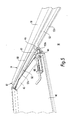
- Figure 1
- is a rear view of a trailer in accordance with the present invention;
- Figure 2
- is a side view of one embodiment of a trailer in accordance with the present invention;
- Figure 3
- is a side view of another embodiment of a trailer in accordance with the present invention;
- Figure 4
- is a part cut-away side view of the embodiment of Figure 3;
- Figure 5
- is a detailed perspective view of the mounting arrangement of the roof hatch ofthe trailer of Figure 3;
- Figure 6
- is a side view of the hatch mounting rails of the trailer of Figure 5;
- Figure 7
- is a part cut-away plan view of the trailer of Figure 3;
- Figure 8
- is a schematic plan view illustrating the process of the present invention; and
- Figure 9
- shows in 6 side views, the application of the process of the present invention to a trailer of the present invention.
- With reference to Figures 1 to 7, the trailer, shown generally at 11, for a lorry tractor unit 10 (Figure 8) will be explained. Firstly, it will be helpful to define that in the context of trailers, the terms 'front' and 'rear' are with respect to the
conventional access doors 12, which are taken to be at the front of the trailer. Thetrailer 11 comprises acontainer 13 defined by twoside walls 14,floor 15,roof 16, end orrear wall 17 and thefront doors 12. - As illustrated,
front doors 12 are of the type which pivot about a vertical axis. The present invention is equally applicable to trailers which include other door arrangements such as half or full-height roller door arrangements. - Many features of the
trailer 11 are largely conventional and do not need to be described in further detail. Indeed, this is a particular advantage of the present system and trailer. Thecontainer 13 is mounted for pivotal movement about an axialhorizontal axis 20 upon achassis 21.Chassis 21 includes additional conventional trailer components such as three pairs ofroad wheels 22 andfront 23 and rear 24 support legs for use when the trailer is not coupled to a tractor unit. Pivotal movement is actuated by means of a pneumatic orhydraulic piston 25, generally vertically mounted but adapted to pivot as required during extension thereof and thus pivoting of thecontainer 13. - One embodiment of a
container 13 is shown in Figure 2 and is typically formed from 5mm aluminium alloy plate and includes reinforcingmembers 30 spaced at approximately 400mm centres. The embodiment shown in Figure 3 is identical save that, for aesthetic and streamlining reasons, the container is clad externally with anappropriate sheet material 31. The use of aluminium means that the container is equally suitable for the transportation of grain/cereals. Indeed the inventive system will find use in the delivery of products to, for example, supermarkets. Supermarkets produce a large quantity of paper and cardboard waste which is presently compacted into small containers in the same manner as in the waste newsprint industry. In this regard, it will be apparent that the trailer could also be refrigerated. - Typically, the
container 13 is around 13m long, 2.55m wide and 2.5m tall. - As is most clearly seen from Figures 4 and 5, the
roof 16 of the trailer includes a hatch comprising anaperture 40 coverable by a horizontallyslidable cover 41. Thecover 41 forms a water-tight seal around theaperture 40. Those skilled in the art will be readily able to devise suitable water-tight arrangements. In the embodiment shown, a compressible rubber seal 42 (Figure 6) is provided around the periphery of theaperture 40. Thecover 41 is arranged to slide into position over theaperture 40 and then down to compress theseal 42 by means of an assembly as will now be described with reference to Figures 5 and 6. - The
cover 41 is provided with anupstanding lip 43 on each side. Each lip carries an outwardly projectingaxle 44 towards each end thereof. Each axle carries awheel 45. - A
channel assembly 50 is mounted upon theroof 16 of the trailer and spaced therefrom byspacers 51. Thechannel assembly 50 includes two separate inwardly directedco-axial channels channel horizontal portion inclined portion doors 12 of the trailer). The right-hand assembly 50 is the mirror image. - Each
channel respective wheel 45 of thecover 41. As will be appreciated, thecover 41 is closed by rolling horizontally along thechannels inclined portions rubber seal 42 around theaperture 40. Opening is the reverse operation. - In the embodiment shown, the
cover 41 is manually operated and secured into either the open or closed positions by means of abolt 60 mounted upon thecover 41 engagingcorresponding front 61 and rear 62 recesses formed in thechannel assembly 50. However, in the preferred embodiments, thecover 41 is remotely operated, such as by means of a hydraulic or pneumatic ram coupled to the cover or by means of an electric motor. In such cases, the inclusion of a bolt is unnecessary. - Within the trailer is transverse wall or headboard 70 (Figures 4 and 7) which is arranged by suitable means to be advanceable towards the
rear wall 17 of the trailer in the direction shown by the arrow in Figure 4. Theheadboard 70 divides thecontainer 13 to form acavity 71 with the of the trailer (namely with the doors 12). - The floor of the trailer is provided with a walking
floor 73 of the type described above. The walking floor comprises a series of parallellongitudinal slats 74. Theslats 74 are arranged to move back and forth with a reciprocating motion,alternate slats 74 moving in opposite directions. Such floors are well known in the art and will not be described in any further detail. - The improvement provided by the present invention will now be described in further detail. With reference to Figures 4 and 7, a
rail 80 is provided at each side of the interior of the trailer internally adjacent the roof thereof. Suspended from therails 80 are a plurality of bags or sacks 72. The bags are generally the same width and height as the interior of the trailer. Their depth, front to back, is generally, but not essentially, of similar dimensions to the width. The sacks are suitably of similar design and construction to those used for transport of bulk builders' materials such as sand and are typically made from natural or synthetic hessian materials. The sacks are suitably suspended from the rails by means of hooks adapted to run along the rails engaging loops provided in each corner of each sack. It will be appreciated that a rail and hook arrangement can readily be replaced by a track arrangement in which the sacks are suspended from the track by a wheeled carriage arrangement or other slidable assembly. - In the preferred embodiments, additional means are provided to arrange that as one sack is moved rearwardly from being adjacent the
front access doors 12, the adjacent back is pulled open. - With particular reference to Figures 8 and 9, the process of the present invention will now be explained. A lorry comprising a
tractor unit 10 and afirst trailer 11A carryingnewsprint reels 80 reverses up to aloading bay 81, of a printing works 82 whereupon the reels are unloaded throughdoors 12 by means of the walking floor. Newspaper waste is removed from the printing process and delivered along a discharge pathway 83 (which is illustrated only schematically) to ahopper 84.Hopper 84 discharges into asecond trailer 11B of identical design tofirst trailer 11A, positioned underneath thehopper 84 throughopen aperture 40 of the hatch in theroof 16oftrailer 11B.Second trailer 11B remains in place on site at the printing works whilst the discharging process is ongoing. - The process operates as follows. A fully laden lorry arrives and discharges its load. It then proceeds to the waste exit area of the
works 82 where the tractor unit deposits the now empty trailer under thehopper 84 for receipt of waste material and retrieves the filled trailer which it then returns to its home depot or elsewhere for disposal. The process is repeated on each subsequent visit. - In a typical arrangement, however, the printing works 82 will have
several hoppers 84 with associateddischarge pathways 83. - Initially, the
transverse headboard 70 will be at the position indicated in Figures 4, 7 and 9a. Thehopper 84discharges waste paper 85 thoughopen aperture 40 into thecavity 71 of the trailer where it falls into afirst hessian sack 72. - As
sack 72 becomes full, one or more sensors (not shown) mounted about theaperture 40 trigger a control mechanism which actuates the walkingfloor 73 for a predetermined time to move thefirst sack 72 towards therear wall 17. The mechanism by which the sacks are suspended from the track orrail 80 automatically causes thenext sack 72 to be opened underneath theaperture 40. Typically this is achieved by an arrangement which retains hold of the suspension means of the front wall of the sack, whilst the rear wall is pulled rearwardly as the first sack is walked in the direction of the rear of the trailer. - The process is repeated (Figures 9a-e) with the
headboard 70 indexing backwardly towards therear wall 17 of the trailer until eachsack - The hatch is then closed and the trailer is then ready to be collected on the next visit of the lorry delivering newsprint. At the site where the waste paper is to be discharged, for example at a landfill site or recycling plant, the trailer discharges the waste by means of the walking floor operating in the reverse direction or by means of tipping the container about
pivot point 20 by means ofram 25. - The
sacks 72 can be loaded directly onto the vessel for transportation to the recycling plant. There is no need for the waste to be separately baled. Typically, the sacks are closable to prevent loss of material and damage from the elements. For example, the upper edge of each sack may be provided with a drawstring closure means, or a cover flap. - The
sacks 72 are recyclable. Thus costs are saved in both time, manpower and in terms of materials, machinery and site costs used in the conventional baling processes. It is estimated that a bag of generally square plan view for the width of a conventional trailer and of the height of a conventional trailer will hold around 2 tonnes of waste paper and that around 5 or 6 such bags could be held within a trailer of generally standard proportions. - The bags can also be used separately from the trailer, for example in a print works under paper shredders, by means of a corresponding rail or track assembly supported by a gantry. The bags can then be removed using a trailer as described above, or by using a conventional solid roofed trailer.
- Whilst attached to the
tractor unit 10, the walkingfloor 73 and thecover 41 closing assembly can be powered by the tractor unit. However, when detached from thetractor unit 10, these components will be powered by means of an on-site power plant at theworks 82. - The present invention reduces the number of on site operations required, avoids the need for raising and lowering heavy containers loaded with waste materials and allows removal of waste to be effected in a straightforward, quick, efficient and cost-effective manner. The present invention also significantly reduces road movements, in ideal cases by 50%. Additionally, in the preferred embodiment, the safety of road delivery is enhanced by the metal construction of the trailer. Furthermore, the present invention can result in capital cost savings by avoiding the need for compactors at the production site, and their ongoing running and maintenance costs.
Whilst having been described with reference to the paper industries, it will be appreciated that the aspects of the present invention are equally suitable for use in other industries, for example in removal of clinical waste. As during use, access into the container is solely via the hatch in the roof, the present invention provides improved hazard security and safety.
Claims (6)
- A trailer comprising a container having a floor, two side walls, a roof, a wall at a first end of the container and at least one access door at a second end of the container; characterised in that a plurality of parallel tracks or rails are mounted within the container generally adjacent the roof thereof and running substantially the whole length of the roof.
- A trailer as claimed in Claim 1 further comprising at least one bag, the bag being open at the top and being so dimensioned in width and height as to correspond generally to the height and width of the trailer.
- A trailer as claimed in Claim 2 comprising a plurality of bags and means for securing the bags to the rails in a manner such that the bags are movable from a first configuration in which all the bags are closed and compressed against each other adjacent the rear doors of the trailer to a second configuration in which the bags are all open with the rear wall of a first bag being substantially adjacent the end wall of the trailer and the front wall of a final bag being substantially adjacent the at least one access door.
- A trailer as claimed in any one of claims 1 to 3 further including an aperture in the roof thereof at a position generally adjacent said second end of the container, said aperture being closable by means of a slidable cover.
- A trailer as claimed in any preceding claim wherein the tracks or rails are adapted to extend through the at least one access door when open.
- A trailer as claimed in any preceding claim, further including a walking floor.
Applications Claiming Priority (3)
| Application Number | Priority Date | Filing Date | Title |
|---|---|---|---|
| GBGB0118556.0A GB0118556D0 (en) | 2001-07-30 | 2001-07-30 | Material and waste transportation |
| GB0118556 | 2001-07-30 | ||
| US09/919,363 US6589002B2 (en) | 2001-07-30 | 2001-07-31 | Material and waste transportation |
Publications (1)
| Publication Number | Publication Date |
|---|---|
| EP1281637A1 true EP1281637A1 (en) | 2003-02-05 |
Family
ID=31995688
Family Applications (1)
| Application Number | Title | Priority Date | Filing Date |
|---|---|---|---|
| EP02255232A Withdrawn EP1281637A1 (en) | 2001-07-30 | 2002-07-26 | Material and waste transportation |
Country Status (3)
| Country | Link |
|---|---|
| US (1) | US6589002B2 (en) |
| EP (1) | EP1281637A1 (en) |
| GB (1) | GB0118556D0 (en) |
Cited By (3)
| Publication number | Priority date | Publication date | Assignee | Title |
|---|---|---|---|---|
| EP1752393A3 (en) * | 2005-08-10 | 2007-03-14 | Derek Edward Sumpter | Material and waste transportation |
| CN101585248A (en) * | 2008-05-21 | 2009-11-25 | 北京航天长峰股份有限公司 | Plate lifting device of press-loading machine |
| ES2340349A2 (en) * | 2008-02-22 | 2010-06-01 | Herg Auxiliar Del Vehiculo Industrial, S.Coop. | Equipment adaptable to vehicle body that allows to classify lamp in different compartments. (Machine-translation by Google Translate, not legally binding) |
Families Citing this family (5)
| Publication number | Priority date | Publication date | Assignee | Title |
|---|---|---|---|---|
| US20040029617A1 (en) * | 2002-08-08 | 2004-02-12 | Mpf Technologies, Inc. | Track system for telecommunications transmission stations |
| US7008001B1 (en) * | 2004-08-23 | 2006-03-07 | Reynolds James F | Automatic tarper |
| US7837428B2 (en) | 2007-03-05 | 2010-11-23 | SA Recycling LLC | Methods and apparatuses for freight container loading |
| US8668425B2 (en) | 2007-03-05 | 2014-03-11 | SA Recycling LLC | Methods and apparatus for freight container loading |
| US9738464B1 (en) | 2012-10-18 | 2017-08-22 | Scott Sakajian | System and method for protecting containers from damage during loading |
Citations (13)
| Publication number | Priority date | Publication date | Assignee | Title |
|---|---|---|---|---|
| US2712797A (en) * | 1951-05-31 | 1955-07-12 | Nat Sugar Refining Company | Convertible load compartment for freight vehicles |
| US3514902A (en) * | 1969-02-14 | 1970-06-02 | Orin M Anderson | Top door mechanism for top loading refuse vehicle |
| US3756469A (en) * | 1970-11-10 | 1973-09-04 | Bulk Liner Corp | Convertible hopper vehicle |
| US3998343A (en) | 1974-12-30 | 1976-12-21 | Fors Vernen E | Cargo moving apparatus for trucks |
| EP0081695A1 (en) | 1981-12-14 | 1983-06-22 | CREFINA Credit and Finance Ets. | Load carrying vehicle |
| US4747747A (en) | 1986-05-05 | 1988-05-31 | Fusco Salvatore M | Conveyor for loading and unloading vehicles and storage facilities |
| GB2294437A (en) * | 1994-10-25 | 1996-05-01 | Goldstar Exports | Meat handling system using overhead rails in buildings and trucks |
| US5551824A (en) | 1993-03-18 | 1996-09-03 | The Hell Company | Articulated refuse collection apparatus |
| GB2307895A (en) | 1995-12-07 | 1997-06-11 | Derek Edward Sumpter | Rubbish Collection System |
| US6079934A (en) * | 1997-11-14 | 2000-06-27 | Beale; Aldon E. | Lift-liner apparatus |
| EP1061012A1 (en) | 1999-06-10 | 2000-12-20 | Derek Edward Sumpter | Material and waste transportation |
| US20010008567A1 (en) * | 1998-03-20 | 2001-07-19 | Burkhardt Henri Jacques | Contained with repositionable slip-sheet to cover outlet |
| EP1120363A1 (en) | 2000-01-25 | 2001-08-01 | Derek Edward Sumpter | Material delivery and waste collection system and lorry trailer for use in such a system |
Family Cites Families (10)
| Publication number | Priority date | Publication date | Assignee | Title |
|---|---|---|---|---|
| US3799374A (en) * | 1971-11-01 | 1974-03-26 | S Weaver | Trash compactor container |
| US3753506A (en) * | 1972-05-03 | 1973-08-21 | Bell & Howell Co | Unitized refuse transfer station |
| US3962965A (en) * | 1972-07-18 | 1976-06-15 | Bennes Marrel | Plant for the compression of garbage |
| DE2701336C2 (en) * | 1977-01-14 | 1978-12-21 | Lindemann Maschinenfabrik Gmbh, 4000 Duesseldorf | Bunker closure |
| DE2820276A1 (en) * | 1978-05-10 | 1979-11-22 | Mabeg Gmbh & Co Ohg | Rubbish unloading device for waste clearance - enables rubbish to slip in front of press ram and to be pushed into forming channel |
| US4431360A (en) * | 1981-07-22 | 1984-02-14 | Mamoru Maeno | Container for the loading and transporting of goods |
| GB2126189B (en) * | 1982-08-27 | 1985-11-06 | Package Control Ltd | Load transporting apparatus |
| GB2159117B (en) * | 1984-05-10 | 1988-02-03 | Devon County Council | Waste transfer packer |
| US5667079A (en) * | 1995-07-24 | 1997-09-16 | Jongebloed; Kenneth W. | Automated multi-grade wastepaper recycle center sorting system |
| GB9606072D0 (en) * | 1996-03-22 | 1996-05-22 | Morris Alan P | Vehicle loading system |
-
2001
- 2001-07-30 GB GBGB0118556.0A patent/GB0118556D0/en not_active Ceased
- 2001-07-31 US US09/919,363 patent/US6589002B2/en not_active Expired - Fee Related
-
2002
- 2002-07-26 EP EP02255232A patent/EP1281637A1/en not_active Withdrawn
Patent Citations (13)
| Publication number | Priority date | Publication date | Assignee | Title |
|---|---|---|---|---|
| US2712797A (en) * | 1951-05-31 | 1955-07-12 | Nat Sugar Refining Company | Convertible load compartment for freight vehicles |
| US3514902A (en) * | 1969-02-14 | 1970-06-02 | Orin M Anderson | Top door mechanism for top loading refuse vehicle |
| US3756469A (en) * | 1970-11-10 | 1973-09-04 | Bulk Liner Corp | Convertible hopper vehicle |
| US3998343A (en) | 1974-12-30 | 1976-12-21 | Fors Vernen E | Cargo moving apparatus for trucks |
| EP0081695A1 (en) | 1981-12-14 | 1983-06-22 | CREFINA Credit and Finance Ets. | Load carrying vehicle |
| US4747747A (en) | 1986-05-05 | 1988-05-31 | Fusco Salvatore M | Conveyor for loading and unloading vehicles and storage facilities |
| US5551824A (en) | 1993-03-18 | 1996-09-03 | The Hell Company | Articulated refuse collection apparatus |
| GB2294437A (en) * | 1994-10-25 | 1996-05-01 | Goldstar Exports | Meat handling system using overhead rails in buildings and trucks |
| GB2307895A (en) | 1995-12-07 | 1997-06-11 | Derek Edward Sumpter | Rubbish Collection System |
| US6079934A (en) * | 1997-11-14 | 2000-06-27 | Beale; Aldon E. | Lift-liner apparatus |
| US20010008567A1 (en) * | 1998-03-20 | 2001-07-19 | Burkhardt Henri Jacques | Contained with repositionable slip-sheet to cover outlet |
| EP1061012A1 (en) | 1999-06-10 | 2000-12-20 | Derek Edward Sumpter | Material and waste transportation |
| EP1120363A1 (en) | 2000-01-25 | 2001-08-01 | Derek Edward Sumpter | Material delivery and waste collection system and lorry trailer for use in such a system |
Cited By (5)
| Publication number | Priority date | Publication date | Assignee | Title |
|---|---|---|---|---|
| EP1752393A3 (en) * | 2005-08-10 | 2007-03-14 | Derek Edward Sumpter | Material and waste transportation |
| ES2340349A2 (en) * | 2008-02-22 | 2010-06-01 | Herg Auxiliar Del Vehiculo Industrial, S.Coop. | Equipment adaptable to vehicle body that allows to classify lamp in different compartments. (Machine-translation by Google Translate, not legally binding) |
| ES2340349R (en) * | 2008-02-22 | 2010-07-08 | Herg Auxiliar Del Vehiculo Industrial, S.Coop. | ADAPTABLE EQUIPMENT TO VEHICLE BODIES WHICH ALLOWS TO CLASSIFY THE GOODS IN DIFFERENT COMPARTMENTS. |
| ES2340349B1 (en) * | 2008-02-22 | 2011-03-18 | Herg Auxiliar Del Vehiculo Industrial, S.Coop. | ADAPTABLE EQUIPMENT TO VEHICLE BODIES THAT ALLOWS TO CLASSIFY LAMERCANCE IN DIFFERENT COMPARTMENTS. |
| CN101585248A (en) * | 2008-05-21 | 2009-11-25 | 北京航天长峰股份有限公司 | Plate lifting device of press-loading machine |
Also Published As
| Publication number | Publication date |
|---|---|
| US6589002B2 (en) | 2003-07-08 |
| GB0118556D0 (en) | 2001-09-19 |
| US20030026678A1 (en) | 2003-02-06 |
Similar Documents
| Publication | Publication Date | Title |
|---|---|---|
| US5035563A (en) | Waste collection system for segregating solid waste into preselected component materials | |
| US4557658A (en) | Material-handling apparatus | |
| US10954086B1 (en) | Container packer system and method | |
| US3013675A (en) | Apparatus for garbage disposal | |
| CA1168190A (en) | Material-handling apparatus | |
| US20090311085A1 (en) | Container packer system and method | |
| JPS6322402A (en) | Packer | |
| US20120141240A1 (en) | Garbage Truck and Self-Contained Loading and Unloading System | |
| EP2058246A1 (en) | Waste Collection Apparatus | |
| EP1281637A1 (en) | Material and waste transportation | |
| US6938960B1 (en) | Top-loading container and cover assembly for collecting, storing, handling, and transporting bulk materials | |
| US6902226B1 (en) | Multi-compartment semi-trailer for transport of recyclable materials | |
| EP1120363B1 (en) | Lorry trailer for use in a material delivery and waste collection system | |
| US4995780A (en) | Handling method for delivering baled solid waste to a balefill | |
| US20030021664A1 (en) | Material and waste transportation | |
| EP1061012B1 (en) | Material and waste transportation | |
| EP1410947A2 (en) | Material and waste transportation | |
| US9511558B1 (en) | Method for collecting and removing refuse from an underground mine | |
| HK1039603A (en) | Material delivery and waste collection system and lorry trailer for use in such a system | |
| WO2010015850A1 (en) | Baling apparatus | |
| AU5400601A (en) | Material and waste transportation | |
| WO2012094711A1 (en) | Waste processing apparatus | |
| US20250178832A1 (en) | Waste collection vehicle | |
| EP1752393A2 (en) | Material and waste transportation | |
| WO1996021579A1 (en) | Improved bulk material carrying truck |
Legal Events
| Date | Code | Title | Description |
|---|---|---|---|
| PUAI | Public reference made under article 153(3) epc to a published international application that has entered the european phase |
Free format text: ORIGINAL CODE: 0009012 |
|
| AK | Designated contracting states |
Designated state(s): AT BE BG CH CY CZ DE DK EE ES FI FR GB GR IE IT LI LU MC NL PT SE SK TR |
|
| AX | Request for extension of the european patent |
Extension state: AL LT LV MK RO SI |
|
| 17P | Request for examination filed |
Effective date: 20030805 |
|
| AKX | Designation fees paid |
Designated state(s): AT BE BG CH CY CZ DE DK EE ES FI FR GB GR IE IT LI LU MC NL PT SE SK TR |
|
| STAA | Information on the status of an ep patent application or granted ep patent |
Free format text: STATUS: THE APPLICATION IS DEEMED TO BE WITHDRAWN |
|
| 18D | Application deemed to be withdrawn |
Effective date: 20050202 |