EP1281560A2 - Integrated axle module with twin electronic torque management - Google Patents
Integrated axle module with twin electronic torque management Download PDFInfo
- Publication number
- EP1281560A2 EP1281560A2 EP02016698A EP02016698A EP1281560A2 EP 1281560 A2 EP1281560 A2 EP 1281560A2 EP 02016698 A EP02016698 A EP 02016698A EP 02016698 A EP02016698 A EP 02016698A EP 1281560 A2 EP1281560 A2 EP 1281560A2
- Authority
- EP
- European Patent Office
- Prior art keywords
- housing
- side shaft
- module
- clutch pack
- shaft
- Prior art date
- Legal status (The legal status is an assumption and is not a legal conclusion. Google has not performed a legal analysis and makes no representation as to the accuracy of the status listed.)
- Granted
Links
- 238000012546 transfer Methods 0.000 claims abstract description 11
- 230000007246 mechanism Effects 0.000 claims description 5
- 238000009826 distribution Methods 0.000 description 13
- 238000004806 packaging method and process Methods 0.000 description 5
- 239000000314 lubricant Substances 0.000 description 4
- 230000010354 integration Effects 0.000 description 3
- 238000009987 spinning Methods 0.000 description 3
- 230000001276 controlling effect Effects 0.000 description 2
- 230000008878 coupling Effects 0.000 description 2
- 238000010168 coupling process Methods 0.000 description 2
- 238000005859 coupling reaction Methods 0.000 description 2
- 230000000694 effects Effects 0.000 description 2
- 238000013461 design Methods 0.000 description 1
- 230000001050 lubricating effect Effects 0.000 description 1
- 238000005461 lubrication Methods 0.000 description 1
- 238000004519 manufacturing process Methods 0.000 description 1
- 238000000034 method Methods 0.000 description 1
- 238000012986 modification Methods 0.000 description 1
- 230000004048 modification Effects 0.000 description 1
- 238000012544 monitoring process Methods 0.000 description 1
- 238000013021 overheating Methods 0.000 description 1
- 230000001105 regulatory effect Effects 0.000 description 1
- 230000003245 working effect Effects 0.000 description 1
Images


Classifications
-
- F—MECHANICAL ENGINEERING; LIGHTING; HEATING; WEAPONS; BLASTING
- F16—ENGINEERING ELEMENTS AND UNITS; GENERAL MEASURES FOR PRODUCING AND MAINTAINING EFFECTIVE FUNCTIONING OF MACHINES OR INSTALLATIONS; THERMAL INSULATION IN GENERAL
- F16H—GEARING
- F16H48/00—Differential gearings
- F16H48/20—Arrangements for suppressing or influencing the differential action, e.g. locking devices
- F16H48/22—Arrangements for suppressing or influencing the differential action, e.g. locking devices using friction clutches or brakes
-
- B—PERFORMING OPERATIONS; TRANSPORTING
- B60—VEHICLES IN GENERAL
- B60K—ARRANGEMENT OR MOUNTING OF PROPULSION UNITS OR OF TRANSMISSIONS IN VEHICLES; ARRANGEMENT OR MOUNTING OF PLURAL DIVERSE PRIME-MOVERS IN VEHICLES; AUXILIARY DRIVES FOR VEHICLES; INSTRUMENTATION OR DASHBOARDS FOR VEHICLES; ARRANGEMENTS IN CONNECTION WITH COOLING, AIR INTAKE, GAS EXHAUST OR FUEL SUPPLY OF PROPULSION UNITS IN VEHICLES
- B60K17/00—Arrangement or mounting of transmissions in vehicles
- B60K17/04—Arrangement or mounting of transmissions in vehicles characterised by arrangement, location, or kind of gearing
- B60K17/16—Arrangement or mounting of transmissions in vehicles characterised by arrangement, location, or kind of gearing of differential gearing
- B60K17/165—Arrangement or mounting of transmissions in vehicles characterised by arrangement, location, or kind of gearing of differential gearing provided between independent half axles
-
- B—PERFORMING OPERATIONS; TRANSPORTING
- B60—VEHICLES IN GENERAL
- B60K—ARRANGEMENT OR MOUNTING OF PROPULSION UNITS OR OF TRANSMISSIONS IN VEHICLES; ARRANGEMENT OR MOUNTING OF PLURAL DIVERSE PRIME-MOVERS IN VEHICLES; AUXILIARY DRIVES FOR VEHICLES; INSTRUMENTATION OR DASHBOARDS FOR VEHICLES; ARRANGEMENTS IN CONNECTION WITH COOLING, AIR INTAKE, GAS EXHAUST OR FUEL SUPPLY OF PROPULSION UNITS IN VEHICLES
- B60K23/00—Arrangement or mounting of control devices for vehicle transmissions, or parts thereof, not otherwise provided for
- B60K23/08—Arrangement or mounting of control devices for vehicle transmissions, or parts thereof, not otherwise provided for for changing number of driven wheels, for switching from driving one axle to driving two or more axles
- B60K23/0808—Arrangement or mounting of control devices for vehicle transmissions, or parts thereof, not otherwise provided for for changing number of driven wheels, for switching from driving one axle to driving two or more axles for varying torque distribution between driven axles, e.g. by transfer clutch
-
- F—MECHANICAL ENGINEERING; LIGHTING; HEATING; WEAPONS; BLASTING
- F16—ENGINEERING ELEMENTS AND UNITS; GENERAL MEASURES FOR PRODUCING AND MAINTAINING EFFECTIVE FUNCTIONING OF MACHINES OR INSTALLATIONS; THERMAL INSULATION IN GENERAL
- F16D—COUPLINGS FOR TRANSMITTING ROTATION; CLUTCHES; BRAKES
- F16D28/00—Electrically-actuated clutches
-
- F—MECHANICAL ENGINEERING; LIGHTING; HEATING; WEAPONS; BLASTING
- F16—ENGINEERING ELEMENTS AND UNITS; GENERAL MEASURES FOR PRODUCING AND MAINTAINING EFFECTIVE FUNCTIONING OF MACHINES OR INSTALLATIONS; THERMAL INSULATION IN GENERAL
- F16H—GEARING
- F16H48/00—Differential gearings
- F16H48/12—Differential gearings without gears having orbital motion
- F16H48/19—Differential gearings without gears having orbital motion consisting of two linked clutches
-
- F—MECHANICAL ENGINEERING; LIGHTING; HEATING; WEAPONS; BLASTING
- F16—ENGINEERING ELEMENTS AND UNITS; GENERAL MEASURES FOR PRODUCING AND MAINTAINING EFFECTIVE FUNCTIONING OF MACHINES OR INSTALLATIONS; THERMAL INSULATION IN GENERAL
- F16H—GEARING
- F16H48/00—Differential gearings
- F16H48/20—Arrangements for suppressing or influencing the differential action, e.g. locking devices
- F16H48/295—Arrangements for suppressing or influencing the differential action, e.g. locking devices using multiple means for force boosting
-
- F—MECHANICAL ENGINEERING; LIGHTING; HEATING; WEAPONS; BLASTING
- F16—ENGINEERING ELEMENTS AND UNITS; GENERAL MEASURES FOR PRODUCING AND MAINTAINING EFFECTIVE FUNCTIONING OF MACHINES OR INSTALLATIONS; THERMAL INSULATION IN GENERAL
- F16H—GEARING
- F16H48/00—Differential gearings
- F16H48/20—Arrangements for suppressing or influencing the differential action, e.g. locking devices
- F16H48/30—Arrangements for suppressing or influencing the differential action, e.g. locking devices using externally-actuatable means
- F16H48/34—Arrangements for suppressing or influencing the differential action, e.g. locking devices using externally-actuatable means using electromagnetic or electric actuators
-
- B—PERFORMING OPERATIONS; TRANSPORTING
- B60—VEHICLES IN GENERAL
- B60K—ARRANGEMENT OR MOUNTING OF PROPULSION UNITS OR OF TRANSMISSIONS IN VEHICLES; ARRANGEMENT OR MOUNTING OF PLURAL DIVERSE PRIME-MOVERS IN VEHICLES; AUXILIARY DRIVES FOR VEHICLES; INSTRUMENTATION OR DASHBOARDS FOR VEHICLES; ARRANGEMENTS IN CONNECTION WITH COOLING, AIR INTAKE, GAS EXHAUST OR FUEL SUPPLY OF PROPULSION UNITS IN VEHICLES
- B60K17/00—Arrangement or mounting of transmissions in vehicles
- B60K17/34—Arrangement or mounting of transmissions in vehicles for driving both front and rear wheels, e.g. four wheel drive vehicles
- B60K17/348—Arrangement or mounting of transmissions in vehicles for driving both front and rear wheels, e.g. four wheel drive vehicles having differential means for driving one set of wheels, e.g. the front, at one speed and the other set, e.g. the rear, at a different speed
- B60K17/35—Arrangement or mounting of transmissions in vehicles for driving both front and rear wheels, e.g. four wheel drive vehicles having differential means for driving one set of wheels, e.g. the front, at one speed and the other set, e.g. the rear, at a different speed including arrangements for suppressing or influencing the power transfer, e.g. viscous clutches
- B60K17/3505—Arrangement or mounting of transmissions in vehicles for driving both front and rear wheels, e.g. four wheel drive vehicles having differential means for driving one set of wheels, e.g. the front, at one speed and the other set, e.g. the rear, at a different speed including arrangements for suppressing or influencing the power transfer, e.g. viscous clutches with self-actuated means, e.g. by difference of speed
-
- F—MECHANICAL ENGINEERING; LIGHTING; HEATING; WEAPONS; BLASTING
- F16—ENGINEERING ELEMENTS AND UNITS; GENERAL MEASURES FOR PRODUCING AND MAINTAINING EFFECTIVE FUNCTIONING OF MACHINES OR INSTALLATIONS; THERMAL INSULATION IN GENERAL
- F16D—COUPLINGS FOR TRANSMITTING ROTATION; CLUTCHES; BRAKES
- F16D27/00—Magnetically- or electrically- actuated clutches; Control or electric circuits therefor
- F16D27/004—Magnetically- or electrically- actuated clutches; Control or electric circuits therefor with permanent magnets combined with electromagnets
-
- F—MECHANICAL ENGINEERING; LIGHTING; HEATING; WEAPONS; BLASTING
- F16—ENGINEERING ELEMENTS AND UNITS; GENERAL MEASURES FOR PRODUCING AND MAINTAINING EFFECTIVE FUNCTIONING OF MACHINES OR INSTALLATIONS; THERMAL INSULATION IN GENERAL
- F16H—GEARING
- F16H48/00—Differential gearings
- F16H48/20—Arrangements for suppressing or influencing the differential action, e.g. locking devices
- F16H48/30—Arrangements for suppressing or influencing the differential action, e.g. locking devices using externally-actuatable means
- F16H48/34—Arrangements for suppressing or influencing the differential action, e.g. locking devices using externally-actuatable means using electromagnetic or electric actuators
- F16H2048/343—Arrangements for suppressing or influencing the differential action, e.g. locking devices using externally-actuatable means using electromagnetic or electric actuators using a rotary motor
-
- F—MECHANICAL ENGINEERING; LIGHTING; HEATING; WEAPONS; BLASTING
- F16—ENGINEERING ELEMENTS AND UNITS; GENERAL MEASURES FOR PRODUCING AND MAINTAINING EFFECTIVE FUNCTIONING OF MACHINES OR INSTALLATIONS; THERMAL INSULATION IN GENERAL
- F16H—GEARING
- F16H25/00—Gearings comprising primarily only cams, cam-followers and screw-and-nut mechanisms
- F16H25/18—Gearings comprising primarily only cams, cam-followers and screw-and-nut mechanisms for conveying or interconverting oscillating or reciprocating motions
- F16H25/186—Gearings comprising primarily only cams, cam-followers and screw-and-nut mechanisms for conveying or interconverting oscillating or reciprocating motions with reciprocation along the axis of oscillation
Definitions
- the present invention relates to axles and differential drives for motor vehicles and more particularly, relates to an axle module with twin electronic torque management for use in a vehicle.
- Torque distribution systems in automotive vehicles have been known for many years.
- torque distribution devices either control the torque being transferred to an axle as found in an in-line “hang-on” all wheel drive system, or may even control the torque being transferred to each individual wheel, as found in a twin "hang-on” all wheel drive system.
- twin "hang-on” all wheel drive systems there is typically a primary driven axle and a secondary driven “hang-on” axle that is connected via a prop shaft or drive shaft and torque transfer couplings to the primary driven axle.
- the primary driven axle also generally includes a differential which divides the torque to the side shafts and then the wheels. The division of torque between the primary and secondary axles is completed by the torque transfer couplings which are usually integrated in the secondary axle.
- a typical prior art twin "hang-on" all wheel drive system provides a permanent drive primary axle.
- the primary axle starts to slip, i.e., the wheels are on a slick road condition or loose gravel, etc.
- the prior art systems will apply torque to each wheel of the secondary axle until the appropriate wheel torque is achieved.
- This provides a traction performance advantage over in-line hang-on torque distribution systems under slip conditions similar to that of a limited slip differential.
- twin torque distribution systems eliminate any need for a differential gear set within the secondary axle.
- axle module that includes an integration of joints into a smaller package, reduced weight and lower side shaft joint angle, in combination with a torque distribution system that also still provides the improved traction performance demanded by all wheel drive systems.
- torque distribution system that can electronically be controlled, thus providing for tuning for each desired vehicle's handling and performance requirements and also creating a preemptive locking system for such all wheel drive systems.
- the object of the present invention is to provide an improved torque distribution system.
- the axle module for use in a vehicle includes a housing wherein a shaft is rotatably supported within the housing.
- the axle module further includes a ring gear connected to the shaft.
- the axle module also includes a clutch pack housing engaged with an end of the shaft.
- a side shaft joint is then arranged within the clutch pack housing.
- a plurality of plates extend from the clutch pack housing and from the side shaft joint.
- the axle module further includes a side shaft connected to a side shaft joint.
- One advantage of the present invention is a new and improved torque distribution device for a vehicle.
- Another advantage of the present invention is that it provides an integrated axle module that includes twin electronic torque management units.
- Yet a further advantage of the present invention is that it reduces the weight and packaging requirements for an axle module in an automotive vehicle.
- Still another advantage of the present invention is that it provides an integrated axle module unit that reduces the side shaft joint angle between the module and wheels.
- a further advantage of the present invention is that it provides a torque distribution system that electronically controls the tuning for the desired vehicle handling and performance requirements.
- Still a further advantage of the present invention is that it provides an axle module that reduces packaging and increases integration of parts in a smaller unit.
- a further advantage of the present invention is that the integrated axle module improves traction while reducing the mass, weight and packaging requirements within the drive train system.
- a further advantage of the present invention is that the axle module is capable of independently controlling each wheels' distributed torque via a motor.
- a further advantage of the present invention is that the integrated axle module can be tuned for the desired vehicles handling and performance requirements.
- the integrated axle module can be used as a preemptive locking device for each axle and wheel independently of each other wheel.
- Still a further advantage of the present invention is the use of the side shaft joint as an inner race of the clutch pack.
- the invention is comprised of an axle module for use in a vehicle axle to control torque to be transmitted to said axle module, said axle module including a housing, drive means supported within said housing, a first and a second inboard side shaft joint arranged within said housing, a first and a second clutch device arranged between said drive means and said first and second inboard side shaft joints respectively, a first and a second ball ramp unit for actuating said first and second clutch devices respectively, a first and a second control means for controlling said first and second ball ramp units respectively independently from each other.
- said drive means inside said housing comprise one shaft rotatably supported in said housing and fixedly connected to outer members of said first and second clutch units respectively.
- said drive means comprise a ring gear connected to said shaft and a pinion engaging said ring gear, said pinion being supported in said housing and drivable from outside said housing.
- Said first and second clutch devices are arranged around said first and second inboard side shaft journals respectively.
- an outer member of said first and second inboard side shaft joints each forms an inner member of said first and second clutch devices respectively.
- first and second control means are a first and a second electric motor which preferably are arranged outside said housing.
- Said first and second electric motors each control one ramp ring of two ramp rings each of said first and second ball ramp units independently from each other to create an axial force that acts on said first and second clutch devices.
- Said clutch devices comprise clutch packs having inner plates connected to an outer member of said inboard side shaft joints respectively and outer plates connected to an outer member of said clutch units respectively. Furthermore between said ball ramp units and said clutch devices there is a pressure plate each to act upon said clutch packs consisting of said inner and outer plates respectively.
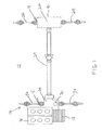
- FIG. 1 schematically illustrates an all wheel drive or a four wheel drive motor vehicle 12 that is a primary front wheel driven vehicle, however, the present invention can also be used on a primary rear wheel drive driven vehicle as well.
- a motor vehicle 12 as shown in Fig. 1 is permanently driven by a front axle 15.
- the motor vehicle 12 is driven by power transferred from the engine 16 through a transaxle or gear box 18 which may be either an automatic or manual gear box.
- the power from the gear box 18 enters the power takeoff 20 of the drive train assembly 36 and finally on through to the front differential 30.
- the power is transferred to the rear axle module 22 via a propeller shaft or driving shaft 24.
- the front differential or front axle module 30 distributes torque between a left hand front side shaft 32 and a right hand front side shaft 34.
- the front axle 15 is a primarily driven axle, with the rear axle 14 only receiving power when needed.
- the preferred embodiment of the present invention is an all wheel drive vehicle wherein torque is distributed to each wheel of the secondary axle in an independent manner depending on which wheels are in a slip condition or are in a non-slip condition with respect to the road.
- the integrated axle module 22 of the present invention could also be used in both the front and rear axles of the all wheel drive unit.
- the drive train 36 includes the front axle 15 which includes a left hand front side shaft 32 and a right hand front side shaft 34.
- the propeller shaft or drive shaft 24 transmits the power from the power take off 20 to a rear axle module 22.
- the rear axle module 22 has a right hand rear side shaft 26 and a left hand rear side shaft 28 extending therefrom to the vehicle wheels which will propel the vehicle in a forward or reverse motion.
- the integrated axle module 22 includes a housing 40.
- One end of the propeller shaft 24 includes a pinion gear which is integrated within the axle module housing 40 and provides the necessary power needed to spin the side shafts 26, 28 to each wheel.
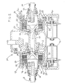
- Fig. 2 shows a cross section of the integrated axle module 22
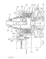
- Fig. 3 shows a cross section of one half of the integrated axle module 22 according to the present invention. An opposite half extends to the other wheel of the rear or front axle and is the mirror image of that shown in Fig. 3.
- the axle module 22 includes a housing 40.
- the housing 40 includes at least one end plate 42 on an end thereof.
- a shaft 44 is rotatably supported within the housing 40 by first and second bearings 46 respectively.
- the shaft 44 has a ring gear 48 attached by any known securing means to an outside surface thereof.
- the ring gear 48 is positioned within the housing 40 such that it mates and engages with the pinion gear which is attached to one end of the propeller shaft 24 of the drive train system.
- the pinion gear When the pinion gear rotates it in turn rotates the ring gear 48 which provides the rotary motion necessary for the rotatably supported shaft 44 within the axle module 22.
- the pinion gear is located within a generally known extension of the housing 40 and is sealed within the integrated axle module housing 40.
- the shaft 44 is connected at each end thereof to a first and second clutch pack housing 50 respectively.
- the preferred embodiment of the shaft 44 has a plurality of teeth 52 on each end thereof and these teeth mate with teeth on an inner circumference of an orifice on the first and second clutch pack housing 50.
- a first and second inboard side shaft joint 54 is arranged within the first and second clutch pack housing 50, respectively.
- the inboard side shaft joint 54 is supported within the housing 50 by first and second bearings 56 respectively.
- the inboard side shaft joint 54 generally has a cup shaped form and includes a pinion 58 extending from one end thereof.
- the pinion 58 is rotatably supported within the hollow end of the shaft 44.
- An inner surface of the clutch pack housing 50 and an outer surface of the inner side shaft joints 54 each include a plurality of friction plates 60 extending therefrom.
- the inner surface of the clutch pack housing 50 and the outer surface of the inboard side shaft joint 54 form a chamber 62.
- the friction plates 60 extend into this chamber 62 in an alternating pattern such that a friction plate 60 of the clutch pack housing 50 is directly adjacent to a friction plate of the inboard side shaft joint 54 and so on throughout the entire chamber 62.
- the inboard side shaft joints 54 are connected to a first and second inner member 64 respectively and then on to the side shafts 26, 28 and eventually the wheels on each side of the automotive vehicle.
- the housing 40 and the inboard side shaft joints 54 are sealed at the ends of the side shaft joints 54 by a seal 66 located between the housing 40 and an outer member of the inboard side shaft joint 54.
- the seal 66 used in combination with a rotating boot member 68, will seal the inboard side shaft joints 54 and their inner joint mechanisms while also allowing for articulation of the side shaft 26, 28 to the wheel.
- This combination of the seal 66 and rotating boot member 68 allows for one lubricant to be used in lubricating the gears and clutch packs 60 while a separate lubricant is used to lubricate the inner workings of the inner side shaft joints 54.
- the rotating boot member 68 is connected via any known means to the outer surface of the inboard side shaft joints 54 and then also connected to the outer surface of the side shaft 26, 28 extending from each side of the axle module 10.
- FIG. 4 An alternate embodiment as shown in Fig. 4 shows a stationary boot member 70 being used to seal both the housing 40 and inboard side shaft joint 54 from outside contaminates.
- the stationary boot member 70 is fixed to the housing 40 via any known securing means such as a metallic clip 76 and then is sealed at the side shaft 26, 28 by use of a seal 72 that is piloted by a bearing 74.
- This allows for the side shaft 26, 28 to rotate within the end of the stationary boot member 70 thus keeping the boot member 70 stationary with relation to the housing 40.
- This arrangement allows for a single lubricant to be used for both the gears and clutch packs 60 along with the inner mechanisms of the inboard side shaft joints 54.
- a first and second pressure plate 78 is located adjacent to the friction plate 60 of the clutch pack housings 50. It should be known that the friction plates 60 are also collectively known or referred to as the clutch packs.
- the pressure plates 78 are capable of applying an axial load to the clutch packs.
- One side of the pressure plate 78 contacts the clutch pack 60 while on the opposite end of the pressure plate a ball ramp unit 80 engages the pressure plate surface.
- the ball ramp unit 80 generally has a ring like appearance and is located directly adjacent to the pressure plate 78 and is attached by any known securing means to an inside surface of the housing 40 or housing end plate 42.
- the ball ramp unit 80 generally includes a first ramp ring 82 and second ramp ring 84 that has a plurality of balls 86 disbursed around the circumference between the first and second ramp rings 82, 84 surfaces.
- the first ramp ring 82 of the ball ramp unit 80 is connected to the housing 40 while the second ramp ring 84 engages a gear set 88.
- the gear set 88 also engages with a motor 90.
- a first and second motor 90 is used to independently control the first and second clutch packs 60, respectively.
- the motors 90 are independently activated by an onboard system computer and will generate the necessary torque to activate the clutch packs 60 after being transmitted through the gear set 88 and then to the second ramp ring 84 of the ball ramp unit.
- the motor 90 When the motor 90 is activated this will transmit through the gear set 88 and ball ramp unit 80 an axial load to the pressure plate 78 which will engage the clutch packs 60 thus producing a transfer of input torque from the pinion shaft, through the clutch pack housing 50 through the friction plates 60 and onward to the inboard side shaft joints 54 and then finally on to the side shafts 26, 28 and then the wheels.
- the torque transmitted to each wheel is independently controlled regardless of what the other three wheels in the automotive vehicle are doing.
- the motors 90 are attached to an outer surface of the axle module housing 40 in a manner such that they are side by side but perform an independent operation to control a separate side shaft of the axle module 22.
- an oil pump may be required to ensure adequate lubrication of the components to prevent overheating depending on the duty cycle of the automotive vehicle.
- the pump is located on the shaft adjacent to the ring gear and thus allows lubricant through the hollow shaft and suitable channels to the clutch packs, bearings, ball ramp units, and the inboard side shaft joints if the configuration used includes the stationary boot members 68.
- Fig. 5 shows a side view of the inboard side shaft joint 54 with the inner joint members used to connect to the side shafts.
- This type of joint in the preferred embodiment is a tripod joint but it should be noted any other type of joint may be used to connect the side shaft to the inboard side shaft joint unit.
- the tripod joint works as is well known in the art in the typical manner described in the prior art.
- each side shaft 26, 28 and each wheel of an automobile vehicle will have a plurality of sensors monitoring numerous factors such as speed, if a vehicle wheel is slipping, if a vehicle wheel is braking, if the vehicle is in a turn, and a host of other identifiable factors that effect the handling and traction of an automotive vehicle.
- the onboard computer senses through its sensor network that a particular wheel in the secondary axle is in a spin condition it then will, via its controller, activate the individual motor 90 on the wheel opposite of the spinning wheel to engage thus sending more torque from the propeller shaft to the wheel that is in a non-slip condition, thus allowing the vehicle to recover from the slip condition.
- the clutch pack housing 50 which is spinning at the axle speed via the pinion gear and the ring gear, will begin transferring an input torque through the friction plates 60 to the inboard side shaft joint 54 thus creating more torque to the side shaft that has the electric motor 90 engaged and removing the vehicle from the slip condition in a quicker time period.
- the motor 90 will be disengaged such that the ball ramp unit 80 is rotated such that the first and second ball ramp rings 82, 84 are at their narrowest width thus disengaging the friction plates 60 and allowing the torque to be evenly distributed between the side shafts 26, 28.
- the side shafts 26, 28 will have an equilibrium speed at which they will spin when the clutch packs 60 are not engaged.
- the motors 90 can also act as an electronic cutoff unit by disconnecting the clutch pack 60 in an open position at all times, thus keeping the ball ramp at its narrowest position thus allowing no torque transfer between the clutch pack housing 50 and the inboard side shaft joints 54, therefore creating no torque to the wheels and allowing the wheel to roll along at hang-on speed.
- the motor 90 is also capable of allowing only a certain percentage of power to be sent to each wheel depending on the road conditions and what is being sensed by the onboard computer sensors.
Abstract
Description
- The present invention relates to axles and differential drives for motor vehicles and more particularly, relates to an axle module with twin electronic torque management for use in a vehicle.
- Torque distribution systems in automotive vehicles have been known for many years. Generally speaking, torque distribution devices either control the torque being transferred to an axle as found in an in-line "hang-on" all wheel drive system, or may even control the torque being transferred to each individual wheel, as found in a twin "hang-on" all wheel drive system. In the twin "hang-on" all wheel drive systems there is typically a primary driven axle and a secondary driven "hang-on" axle that is connected via a prop shaft or drive shaft and torque transfer couplings to the primary driven axle. The primary driven axle also generally includes a differential which divides the torque to the side shafts and then the wheels. The division of torque between the primary and secondary axles is completed by the torque transfer couplings which are usually integrated in the secondary axle.
- A typical prior art twin "hang-on" all wheel drive system provides a permanent drive primary axle. However, when the primary axle starts to slip, i.e., the wheels are on a slick road condition or loose gravel, etc., the prior art systems will apply torque to each wheel of the secondary axle until the appropriate wheel torque is achieved. This provides a traction performance advantage over in-line hang-on torque distribution systems under slip conditions similar to that of a limited slip differential. It should be noted that the twin torque distribution systems eliminate any need for a differential gear set within the secondary axle.
- However, with the increased traction performance of the prior art systems, a substantial number of drawbacks are encountered such as complexity of the torque distribution system, the weight of the torque distribution system and the cost to manufacture and design such systems. Furthermore, the prior art torque distribution systems generally have axles that are bulky and difficult to package in the small area left for the drive-line systems. Furthermore, the increased cross vehicle width of most twin axle devices causes the inboard side shaft joints to be positioned or shifted towards the wheel, thus leading to packaging conflicts with the chassis components and an increase in joint angles which effects the efficiency and durability of constant velocity joints and the like. In the recent past there have been numerous attempts to overcome the above identified problems in the area of conventional drive-line systems. Most of these systems try to develop a method to reduce the mass, packaging requirements and joint angles of conventional axles by integrating the inboard side shaft joints and the differential housing. Some of these proposals have been successful in attempting to provide a lower weight, lower cost or smaller side shaft joint angle needed in current all wheel drive vehicles. However, no such integration with a twin axle device including speed sensing or electronically controlled clutch packs, has been provided to date.
- Therefore, there is a need in the art for an axle module that includes an integration of joints into a smaller package, reduced weight and lower side shaft joint angle, in combination with a torque distribution system that also still provides the improved traction performance demanded by all wheel drive systems. Furthermore, there is a need in the art for a torque distribution system that can electronically be controlled, thus providing for tuning for each desired vehicle's handling and performance requirements and also creating a preemptive locking system for such all wheel drive systems.
- The object of the present invention is to provide an improved torque distribution system.
- To achieve the foregoing objects the axle module for use in a vehicle includes a housing wherein a shaft is rotatably supported within the housing. The axle module further includes a ring gear connected to the shaft. The axle module also includes a clutch pack housing engaged with an end of the shaft. A side shaft joint is then arranged within the clutch pack housing. A plurality of plates extend from the clutch pack housing and from the side shaft joint. The axle module further includes a side shaft connected to a side shaft joint.
- One advantage of the present invention is a new and improved torque distribution device for a vehicle.
- Another advantage of the present invention is that it provides an integrated axle module that includes twin electronic torque management units.
- Yet a further advantage of the present invention is that it reduces the weight and packaging requirements for an axle module in an automotive vehicle.
- Still another advantage of the present invention is that it provides an integrated axle module unit that reduces the side shaft joint angle between the module and wheels.
- A further advantage of the present invention is that it provides a torque distribution system that electronically controls the tuning for the desired vehicle handling and performance requirements.
- Still a further advantage of the present invention is that it provides an axle module that reduces packaging and increases integration of parts in a smaller unit.
- A further advantage of the present invention is that the integrated axle module improves traction while reducing the mass, weight and packaging requirements within the drive train system.
- A further advantage of the present invention is that the axle module is capable of independently controlling each wheels' distributed torque via a motor.
- A further advantage of the present invention is that the integrated axle module can be tuned for the desired vehicles handling and performance requirements.
- Yet a further advantage of the present invention is that the integrated axle module can be used as a preemptive locking device for each axle and wheel independently of each other wheel.
- Still a further advantage of the present invention is the use of the side shaft joint as an inner race of the clutch pack.
- The invention is comprised of an axle module for use in a vehicle axle to control torque to be transmitted to said axle module, said axle module including a housing, drive means supported within said housing, a first and a second inboard side shaft joint arranged within said housing, a first and a second clutch device arranged between said drive means and said first and second inboard side shaft joints respectively, a first and a second ball ramp unit for actuating said first and second clutch devices respectively, a first and a second control means for controlling said first and second ball ramp units respectively independently from each other. In this said drive means inside said housing comprise one shaft rotatably supported in said housing and fixedly connected to outer members of said first and second clutch units respectively. Further said drive means comprise a ring gear connected to said shaft and a pinion engaging said ring gear, said pinion being supported in said housing and drivable from outside said housing.
- Said first and second clutch devices are arranged around said first and second inboard side shaft journals respectively. Herein an outer member of said first and second inboard side shaft joints each forms an inner member of said first and second clutch devices respectively.
- Furthermore said first and second control means are a first and a second electric motor which preferably are arranged outside said housing. Said first and second electric motors each control one ramp ring of two ramp rings each of said first and second ball ramp units independently from each other to create an axial force that acts on said first and second clutch devices. Said clutch devices comprise clutch packs having inner plates connected to an outer member of said inboard side shaft joints respectively and outer plates connected to an outer member of said clutch units respectively. Furthermore between said ball ramp units and said clutch devices there is a pressure plate each to act upon said clutch packs consisting of said inner and outer plates respectively.
- Other objects, features, and advantages of the present invention will become apparent from the subsequent description and appended claims taken in conjunction with the accompanying drawings.
-
- Fig. 1 shows a schematic view of a vehicle system according to the present invention.
- Fig. 2 shows a cross-section of the axle module according to the present invention.
- Fig. 3 shows a partial cross section of the axle module according to the present invention.
- Fig. 4 shows a partial cross section of an alternative embodiment of the axle module according to the present invention.
- Fig. 5 shows a side view of a side shaft joint according to the present invention.
-
- Referring to the drawings, an integrated
axle module 22 according to the present invention is shown. Fig. 1 schematically illustrates an all wheel drive or a four wheeldrive motor vehicle 12 that is a primary front wheel driven vehicle, however, the present invention can also be used on a primary rear wheel drive driven vehicle as well. - A
motor vehicle 12 as shown in Fig. 1 is permanently driven by a front axle 15. Themotor vehicle 12 is driven by power transferred from theengine 16 through a transaxle orgear box 18 which may be either an automatic or manual gear box. The power from thegear box 18 enters thepower takeoff 20 of thedrive train assembly 36 and finally on through to thefront differential 30. When there is a demand for power the power is transferred to therear axle module 22 via a propeller shaft or drivingshaft 24. At therear axle module 22 power splits to a left handrear side shaft 26 and a right handrear side shaft 28 for distribution to the wheels at the rear of the vehicle. The front differential orfront axle module 30 distributes torque between a left handfront side shaft 32 and a right handfront side shaft 34. In an all wheel drive vehicle, power is delivered to both therear axle module 22 and the front differential 30, the front axle 15 is a primarily driven axle, with therear axle 14 only receiving power when needed. The preferred embodiment of the present invention is an all wheel drive vehicle wherein torque is distributed to each wheel of the secondary axle in an independent manner depending on which wheels are in a slip condition or are in a non-slip condition with respect to the road. Theintegrated axle module 22 of the present invention could also be used in both the front and rear axles of the all wheel drive unit. - The
drive train 36 includes the front axle 15 which includes a left handfront side shaft 32 and a right handfront side shaft 34. The propeller shaft or driveshaft 24 transmits the power from the power take off 20 to arear axle module 22. Therear axle module 22 has a right handrear side shaft 26 and a left handrear side shaft 28 extending therefrom to the vehicle wheels which will propel the vehicle in a forward or reverse motion. Theintegrated axle module 22 includes ahousing 40. One end of thepropeller shaft 24 includes a pinion gear which is integrated within theaxle module housing 40 and provides the necessary power needed to spin theside shafts - Fig. 2 shows a cross section of the
integrated axle module 22 and Fig. 3 shows a cross section of one half of theintegrated axle module 22 according to the present invention. An opposite half extends to the other wheel of the rear or front axle and is the mirror image of that shown in Fig. 3. Theaxle module 22 includes ahousing 40. Thehousing 40 includes at least oneend plate 42 on an end thereof. Ashaft 44 is rotatably supported within thehousing 40 by first andsecond bearings 46 respectively. Theshaft 44 has aring gear 48 attached by any known securing means to an outside surface thereof. Thering gear 48 is positioned within thehousing 40 such that it mates and engages with the pinion gear which is attached to one end of thepropeller shaft 24 of the drive train system. When the pinion gear rotates it in turn rotates thering gear 48 which provides the rotary motion necessary for the rotatably supportedshaft 44 within theaxle module 22. The pinion gear is located within a generally known extension of thehousing 40 and is sealed within the integratedaxle module housing 40. Theshaft 44 is connected at each end thereof to a first and secondclutch pack housing 50 respectively. The preferred embodiment of theshaft 44 has a plurality ofteeth 52 on each end thereof and these teeth mate with teeth on an inner circumference of an orifice on the first and secondclutch pack housing 50. A first and second inboard side shaft joint 54 is arranged within the first and secondclutch pack housing 50, respectively. The inboard side shaft joint 54 is supported within thehousing 50 by first andsecond bearings 56 respectively. The inboard side shaft joint 54 generally has a cup shaped form and includes apinion 58 extending from one end thereof. Thepinion 58 is rotatably supported within the hollow end of theshaft 44. - An inner surface of the
clutch pack housing 50 and an outer surface of the inner side shaft joints 54 each include a plurality offriction plates 60 extending therefrom. The inner surface of theclutch pack housing 50 and the outer surface of the inboard side shaft joint 54 form achamber 62. Thefriction plates 60 extend into thischamber 62 in an alternating pattern such that afriction plate 60 of theclutch pack housing 50 is directly adjacent to a friction plate of the inboard side shaft joint 54 and so on throughout theentire chamber 62. The inboard side shaft joints 54 are connected to a first and secondinner member 64 respectively and then on to theside shafts - The
housing 40 and the inboard side shaft joints 54 are sealed at the ends of the side shaft joints 54 by a seal 66 located between thehousing 40 and an outer member of the inboard side shaft joint 54. The seal 66 used in combination with arotating boot member 68, will seal the inboard side shaft joints 54 and their inner joint mechanisms while also allowing for articulation of theside shaft rotating boot member 68 allows for one lubricant to be used in lubricating the gears andclutch packs 60 while a separate lubricant is used to lubricate the inner workings of the inner side shaft joints 54. Therotating boot member 68 is connected via any known means to the outer surface of the inboard side shaft joints 54 and then also connected to the outer surface of theside shaft - An alternate embodiment as shown in Fig. 4 shows a
stationary boot member 70 being used to seal both thehousing 40 and inboard side shaft joint 54 from outside contaminates. Thestationary boot member 70 is fixed to thehousing 40 via any known securing means such as a metallic clip 76 and then is sealed at theside shaft bearing 74. This allows for theside shaft stationary boot member 70 thus keeping theboot member 70 stationary with relation to thehousing 40. This arrangement allows for a single lubricant to be used for both the gears andclutch packs 60 along with the inner mechanisms of the inboard side shaft joints 54. - A first and
second pressure plate 78 is located adjacent to thefriction plate 60 of theclutch pack housings 50. It should be known that thefriction plates 60 are also collectively known or referred to as the clutch packs. Thepressure plates 78 are capable of applying an axial load to the clutch packs. One side of thepressure plate 78 contacts theclutch pack 60 while on the opposite end of the pressure plate aball ramp unit 80 engages the pressure plate surface. Theball ramp unit 80 generally has a ring like appearance and is located directly adjacent to thepressure plate 78 and is attached by any known securing means to an inside surface of thehousing 40 orhousing end plate 42. Theball ramp unit 80 generally includes afirst ramp ring 82 andsecond ramp ring 84 that has a plurality of balls 86 disbursed around the circumference between the first and second ramp rings 82, 84 surfaces. Thefirst ramp ring 82 of theball ramp unit 80 is connected to thehousing 40 while thesecond ramp ring 84 engages a gear set 88. The gear set 88 also engages with amotor 90. It should be noted that a first andsecond motor 90 is used to independently control the first and second clutch packs 60, respectively. Themotors 90 are independently activated by an onboard system computer and will generate the necessary torque to activate the clutch packs 60 after being transmitted through the gear set 88 and then to thesecond ramp ring 84 of the ball ramp unit. When themotor 90 is activated this will transmit through the gear set 88 andball ramp unit 80 an axial load to thepressure plate 78 which will engage the clutch packs 60 thus producing a transfer of input torque from the pinion shaft, through theclutch pack housing 50 through thefriction plates 60 and onward to the inboard side shaft joints 54 and then finally on to theside shafts motor 90 being separately regulated by a controller of the automotive vehicle the torque transmitted to each wheel is independently controlled regardless of what the other three wheels in the automotive vehicle are doing. In the preferred embodiment themotors 90 are attached to an outer surface of theaxle module housing 40 in a manner such that they are side by side but perform an independent operation to control a separate side shaft of theaxle module 22. It should be noted that in an alternative embodiment an oil pump may be required to ensure adequate lubrication of the components to prevent overheating depending on the duty cycle of the automotive vehicle. The pump is located on the shaft adjacent to the ring gear and thus allows lubricant through the hollow shaft and suitable channels to the clutch packs, bearings, ball ramp units, and the inboard side shaft joints if the configuration used includes thestationary boot members 68. - Fig. 5 shows a side view of the inboard side shaft joint 54 with the inner joint members used to connect to the side shafts. This type of joint in the preferred embodiment is a tripod joint but it should be noted any other type of joint may be used to connect the side shaft to the inboard side shaft joint unit. The tripod joint works as is well known in the art in the typical manner described in the prior art.
- In operation the
integrated axle module 22 with twin electronic torque management is controlled by an onboard computer control system. Generally speaking eachside shaft individual motor 90 on the wheel opposite of the spinning wheel to engage thus sending more torque from the propeller shaft to the wheel that is in a non-slip condition, thus allowing the vehicle to recover from the slip condition. This occurs by having themotor 90 activate and rotate through the gear set 88, such that thesecond ramp ring 84 of theball ramp unit 80 rotates a predetermined distance based on the gearing used in the gear set. This then causes the balls 86 to engage with thefirst ramp 82 and create an axial force by separating theramps second ramp 84 to thepressure plate 78 which will engage thefriction plate 60 within the clutch pack. When thefriction plates 60 contact with one another and compress into one another, theclutch pack housing 50, which is spinning at the axle speed via the pinion gear and the ring gear, will begin transferring an input torque through thefriction plates 60 to the inboard side shaft joint 54 thus creating more torque to the side shaft that has theelectric motor 90 engaged and removing the vehicle from the slip condition in a quicker time period. Once. the slip condition has been overcome and the vehicle wheels are running at equilibrium themotor 90 will be disengaged such that theball ramp unit 80 is rotated such that the first and second ball ramp rings 82, 84 are at their narrowest width thus disengaging thefriction plates 60 and allowing the torque to be evenly distributed between theside shafts side shafts motors 90 can also act as an electronic cutoff unit by disconnecting theclutch pack 60 in an open position at all times, thus keeping the ball ramp at its narrowest position thus allowing no torque transfer between theclutch pack housing 50 and the inboard side shaft joints 54, therefore creating no torque to the wheels and allowing the wheel to roll along at hang-on speed. Hence, themotor 90 is also capable of allowing only a certain percentage of power to be sent to each wheel depending on the road conditions and what is being sensed by the onboard computer sensors. Therefore, at equilibrium conditions, the secondary axle side shafts spin at axle speed and the pinion gear will be spinning thering gear 48 and hence the clutch pack housing at axle speed but there will be no torque or power transfer through the clutch packs until a condition occurs that requires more torque to be transferred from the primary driven axle to the secondary axle. - The present invention has been described in an illustrative manner. It is to be understood that the terminology which has been used is intended to be in the nature of words of description rather than of limitation.
- Many modifications and variations of the present invention are possible in light of the above teachings. Therefore, within the scope of the appended claims, the present invention may be practiced otherwise than as specifically described.
Claims (28)
- An axle module (22), said module including:a housing (40);a shaft (44) rotatably supported within said housing (40);a ring gear (48) connected to said shaft (44);a clutch pack housing (40) engaged with an end of said shaft (44);a side shaft joint (54) arranged within said clutch pack housing (40);a plurality of plates (60) extending from said clutch pack housing (40) and said side shaft joint (54); anda side shaft (26, 28) connected to said side shaft joint (54).
- The module of claim 1 further including an engagement mechanism, said engagement mechanism activates a clutch pack (60) within said clutch pack housing (40).
- The module of anyone of claims 1 or 2 further including a rotating boot member (68) engaging said side shaft joint (54) and said side shaft (26, 28).
- The module of anyone of claims 1 or 2 further including a stationary boot member (70) engaging said side shaft (26, 28) and said housing (40).
- The module of anyone of claims 1 to 4, wherein said plurality of plates (60) alternate in extending from said clutch pack housing (40) and said side shaft joint (54).
- The module of anyone of claims 2 to 5, wherein said engagement mechanism engages a ball ramp unit (80) that provides an axial force.
- The module of claim 6 wherein said ball ramp unit (80) contacts a pressure plate (78) on one side thereof and said clutch pack (60) contacts said pressure plate (78) on an opposite side thereof.
- The module of claim 7 wherein said pressure plate (78) transfers axial load from said ball ramp unit (80) to said clutch packs (60) by contacting said plurality of plates with one another.
- The module of claim 8 wherein said engaged plurality of plates (60) transfer input torque from said ring gear (48) to said side shaft joints (54).
- The module of claim 9 wherein torque transfer is controlled for each side shaft joint (54) of the axle module (22) independently.
- An axle module (22) for use in a vehicle (12) having a plurality of wheels, said module including:a housing (40);a shaft (44) rotatably supported within said housing (40);a ring gear (48) connected to said shaft (44);a pinion gear engaged with said ring gear (48);a clutch pack housing (50) connected to an end of said shaft (44);an inboard side shaft joint (54) arranged within said clutch pack housing (44), said clutch pack housing (44) and said inboard side shaft joint (54) defines a chamber (62);a clutch pack (60) arranged within said chamber (62), said clutch pack including a plurality of friction plates (60) alternately connected to said clutch pack housing (44) and said inboard side shaft joint (54); anda side shaft (26, 28) connected to said inboard side shaft joint (54).
- The module of claim 11 further including a motor (90) connected to said housing (40).
- The module of claim 12 further including a ball ramp unit (80) connected to said motor (90) by a gear set (88), said ball ramp unit (80) arranged adjacent to a pressure plate (78).
- The module of claim 13 wherein said pressure plate (78) is adjacent to said clutch pack (60).
- The module of anyone of claims 13 or 14, wherein said ball ramp unit (80) creates an axial force that acts on said pressure plate (78).
- The module of anyone of claims 13 to 15, wherein said pressure plate (78) compresses said friction plates (60) and allows for input torque transfer from said ring gear (48) to said inboard side shaft joint (54).
- The module of anyone of claims 11 to 16 further including a second clutch pack housing (50) and a second inboard side shaft joint (54) connected to a second end of said shaft (44).
- The module of claim 17 wherein a second motor (90) controls a second clutch pack (60) independently of said clutch pack (60), allowing for torque control to each wheel to be independent from every other wheel.
- The module of anyone of claims 11 to 18, wherein a boot member (68, 70) is stationary or rotates with respect to said housing (40).
- An axle module (22) for use in a vehicle (12) to control torque transmitted to each wheel independently, said axle module (22) including:a housing (40);a shaft (44) rotatably supported within said housing (40);a ring gear (48) connected to said shaft (44); a pinion gear engaging said ring gear (48);a first and second clutch pack housing (50) arranged on a first and second end of said shaft (44), respectively;a first and second inboard side shaft joint (54) arranged within said first and second clutch pack housing (50), respectively, said clutch pack housings (50) and said inboard side shaft joints (54) each define a chamber (62);a first and second plurality of friction plates (60) extending into said chamber (62) from an inside surface of said clutch pack housings (50) and an outside surface of said inboard side shaft joints (54), said friction plates (60) alternately attached to said clutch pack housings (50) and said inboard side shaft joints (54) respectively;a first and second pressure plate (78) adjacent to said first and second clutch pack housing (50), respectively;a first and second ramp unit (80) adjacent to said pressure plates (78) respectively;a first and second motor (90) controlling said first and second ramp unit (80), respectively, by a first and second gear set (88); anda first and second side shaft (26, 28) connected to said first and second inboard side shaft joints (54), respectively, each motor (90) independently controlling torque to a wheel by use of said clutch packs (60).
- An axle module (22) for use in a vehicle axle to control torque to be transmitted to said axle module, said axle module (22) including:a housing (40);drive means supported within said housing (40);a first and a second inboard side shaft joint (54) arranged within said housing (40);a first and a second clutch device arranged between said drive means and said first and second inboard side shaft joints (54) respectively;a first and a second ball ramp unit (80) for actuating said first and second clutch devices respectively;a first and a second control means for controlling said first and second ball ramp units (80) respectively independently from each other.
- An axle module according to claim 21, wherein said drive means inside said housing (40) comprise one shaft (44) rotatingly supported within said housing (40), said one shaft being fixedly connected to an outer member each of said first and second clutch units.
- An axle module according to claim 22, wherein said drive means further comprise a ring gear (48) connected to said shaft (44) and a pinion gear being supported in said housing and drivable from outside said housing (40).
- An axle module according to one of claims 21 to 23, wherein said first and second clutch devices are arranged around said first and second inboard side shaft joints (54) respectively.
- An axle module according to claim 24, wherein outer members of said first and second inboard drive shaft joints (54) form inner members of said first and second clutch devices respectively.
- An axle module according to one of claims 21 to 25, wherein said first and second control means are a first and a second electric motor (90) respectively.
- An axle module according to claim 26, wherein said first and second electric motors are arranged outside said housing (40).
- An axle module according to one of claims 21 to 27, wherein said first and second control means each control a ramp ring of said first and second ball ramp units respectively.
Applications Claiming Priority (2)
| Application Number | Priority Date | Filing Date | Title |
|---|---|---|---|
| US922080 | 2001-08-03 | ||
| US09/922,080 US6533090B2 (en) | 2001-08-03 | 2001-08-03 | Integrated axle module with twin electronic torque management |
Publications (3)
| Publication Number | Publication Date |
|---|---|
| EP1281560A2 true EP1281560A2 (en) | 2003-02-05 |
| EP1281560A3 EP1281560A3 (en) | 2005-12-21 |
| EP1281560B1 EP1281560B1 (en) | 2009-07-08 |
Family
ID=25446478
Family Applications (1)
| Application Number | Title | Priority Date | Filing Date |
|---|---|---|---|
| EP02016698A Expired - Lifetime EP1281560B1 (en) | 2001-08-03 | 2002-07-26 | Integrated axle module with twin electronic torque management |
Country Status (4)
| Country | Link |
|---|---|
| US (1) | US6533090B2 (en) |
| EP (1) | EP1281560B1 (en) |
| JP (1) | JP2003106340A (en) |
| DE (1) | DE60232845D1 (en) |
Cited By (7)
| Publication number | Priority date | Publication date | Assignee | Title |
|---|---|---|---|---|
| GB2393224A (en) * | 2002-08-02 | 2004-03-24 | Visteon Global Tech Inc | Axle differential with ball-screw actuated clutches |
| EP1527938A2 (en) | 2003-11-03 | 2005-05-04 | New Venture Gear, Inc. | Electronically-controlled rear drive module for all-wheel drive vehicle |
| DE102006025071A1 (en) * | 2006-05-30 | 2007-12-06 | Zf Friedrichshafen Ag | Gear unit for guiding a drive torque from a drive shaft to two output shafts |
| WO2010038148A1 (en) * | 2008-10-03 | 2010-04-08 | Eaton Corporation | Rear drive module wheel disconnect |
| WO2014024042A2 (en) * | 2012-08-09 | 2014-02-13 | Gkn Driveline North America, Inc. | All wheel drive electronic torque differential disconnect |
| DE102013217590A1 (en) | 2013-09-04 | 2015-03-05 | Zf Friedrichshafen Ag | Drivable axle for a motor vehicle |
| US10493978B2 (en) | 2016-03-18 | 2019-12-03 | Gkn Automotive Ltd. | Electric drive |
Families Citing this family (53)
| Publication number | Priority date | Publication date | Assignee | Title |
|---|---|---|---|---|
| SE519490C2 (en) * | 2001-07-05 | 2003-03-04 | Haldex Traction Ab | Ball arrangement in a torque transmitting device |
| US6779420B2 (en) * | 2002-03-20 | 2004-08-24 | Gkn Automotive, Inc. | Integrated twin pull electronic torque management axle |
| US7211019B2 (en) * | 2003-02-21 | 2007-05-01 | Magna Powertrain Usa, Inc. | Torque vectoring drive mechanism having a power sharing control system |
| US7175557B2 (en) * | 2003-02-21 | 2007-02-13 | Magna Powertrain Usa, Inc. | Torque vectoring device having an electric motor/brake actuator and friction clutch |
| US7175558B2 (en) * | 2003-03-07 | 2007-02-13 | Magna Powertrain Usa, Inc. | Torque vectoring drive units with worm driven ball screw clutches |
| US6790154B1 (en) | 2003-03-21 | 2004-09-14 | Borgwarner, Inc. | Rear axle having electromagnetic clutches and geared differential |
| US7083033B2 (en) * | 2003-03-27 | 2006-08-01 | Tochigi Fuji Sangyo Kabushiki Kaisha | Torque transmission apparatus |
| US7983820B2 (en) * | 2003-07-02 | 2011-07-19 | Caterpillar Inc. | Systems and methods for providing proxy control functions in a work machine |
| US7516244B2 (en) * | 2003-07-02 | 2009-04-07 | Caterpillar Inc. | Systems and methods for providing server operations in a work machine |
| US7070036B2 (en) * | 2003-08-29 | 2006-07-04 | Muncie Power Products, Inc. | Power takeoff device |
| DE20314141U1 (en) * | 2003-09-10 | 2005-01-27 | Gkn Automotive Gmbh | axial setting |
| US6976553B1 (en) | 2004-02-19 | 2005-12-20 | Polaris Industries Inc. | Multimodal vehicle traction system |
| US20050205376A1 (en) * | 2004-03-19 | 2005-09-22 | Kemper Yves J | Ramp actuator |
| US6988604B2 (en) * | 2004-04-19 | 2006-01-24 | Borgwarner Inc. | Friction clutch pack having a motor driven ball ramp operator |
| US6962227B1 (en) | 2004-05-07 | 2005-11-08 | Magna Drivetrain Of America, Inc. | Torque vectoring drive axle assembly |
| US7258187B2 (en) * | 2004-05-14 | 2007-08-21 | Magna Powertrain Usa, Inc. | Torque vectoring axle |
| US7044880B2 (en) * | 2004-05-20 | 2006-05-16 | Magna Powertrain, Inc. | Torque distributing differential assembly |
| US7086982B2 (en) * | 2004-05-24 | 2006-08-08 | Magna Powertrain Usa, Inc. | Torque vectoring drive axle assembly |
| US7059990B2 (en) * | 2004-05-25 | 2006-06-13 | Magna Powertrain, Inc. | Torque vectoring drive axle assembly |
| US7811194B2 (en) | 2004-05-25 | 2010-10-12 | Magna Powertrain Usa, Inc. | Differential assembly with torque vectoring drive mechanism |
| US7004876B2 (en) * | 2004-05-27 | 2006-02-28 | Magna Powertrain, Inc. | Torque vectoring limited slip differential assembly |
| US20050266953A1 (en) * | 2004-06-01 | 2005-12-01 | Dumitru Puiu | Drive axle assembly with torque distributing limited slip differential unit |
| JP4425742B2 (en) * | 2004-08-18 | 2010-03-03 | Ntn株式会社 | Constant velocity joint boots |
| US7766116B1 (en) | 2004-12-16 | 2010-08-03 | Polaris Industries Inc. | Vehicle with optimized on-demand front drive system |
| US7361113B2 (en) | 2005-01-18 | 2008-04-22 | Magna Powertrain Usa, Inc. | Torque distributing drive unit for motor vehicles |
| US7175559B2 (en) * | 2005-01-26 | 2007-02-13 | Magna Powertrain Usa, Inc. | Torque vectoring axle assembly |
| DE102005023389A1 (en) * | 2005-05-21 | 2006-11-23 | Zf Friedrichshafen Ag | Device for setting the transmission capabilities of two frictional switching elements |
| US7344469B2 (en) * | 2005-06-28 | 2008-03-18 | Magna Powertrain Usa, Inc. | Torque distributing drive mechanism with ravigneaux gearset |
| US7503416B2 (en) * | 2005-06-28 | 2009-03-17 | Magna Powertrain Usa, Inc. | Torque distributing drive mechanism with limited slip |
| AT8907U1 (en) * | 2005-07-29 | 2007-02-15 | Magna Drivetrain Ag & Co Kg | DISTRIBUTION GEAR WITH TWO NON-INDEPENDENT COUPLINGS FOR CONTROLLING THE MOMENT DISTRIBUTION TO TWO AXES, CLUTCH FOR SUCH AND METHOD FOR CALIBRATION THEREOF |
| JP4821208B2 (en) * | 2005-08-08 | 2011-11-24 | 日産自動車株式会社 | Vehicle driving force distribution device |
| JP2007154966A (en) * | 2005-12-02 | 2007-06-21 | Toyota Motor Corp | Vehicular driving force distribution device |
| DE102005061267B4 (en) * | 2005-12-20 | 2007-12-06 | Gkn Driveline International Gmbh | Differential arrangement with two jointly operated Axialverstellvorrichtungen |
| JP5247135B2 (en) * | 2007-05-18 | 2013-07-24 | Gknドライブラインジャパン株式会社 | Driving force distribution transmission device |
| US20090321208A1 (en) * | 2008-06-26 | 2009-12-31 | Schrand Edward V | Secondary drive axle disconnect for a motor vehicle |
| US8042642B2 (en) | 2008-08-14 | 2011-10-25 | American Axle & Manufacturing, Inc. | Motor vehicle with disconnectable all-wheel drive system |
| US8095288B2 (en) * | 2009-04-17 | 2012-01-10 | Ford Global Technologies, Llc | Reducing oscillations in a motor vehicle driveline |
| US8388486B2 (en) * | 2009-08-11 | 2013-03-05 | Magna Powertrain Of America, Inc. | AWD vehicle with active disconnect coupling having multi-stage ball ramp |
| US9003925B2 (en) * | 2011-08-10 | 2015-04-14 | Gkn Driveline North America, Inc. | Twin electronic torque management device |
| US9079495B2 (en) | 2012-06-15 | 2015-07-14 | American Axle & Manufacturing, Inc. | Disconnectable driveline with a multi-speed RDM and PTU |
| US8986148B2 (en) | 2012-10-05 | 2015-03-24 | American Axle & Manufacturing, Inc. | Single speed and two-speed disconnecting axle arrangements |
| US9476492B2 (en) * | 2014-01-24 | 2016-10-25 | Dana Automotive Systems Group, Llc | Active limited slip differential |
| US9346354B2 (en) | 2014-03-03 | 2016-05-24 | American Axle & Manufacturing, Inc. | Disconnecting driveline component |
| US10408323B2 (en) | 2014-07-16 | 2019-09-10 | Dana Automotive Systems Group, Llc | Drive unit with twin side shaft torque coupling |
| US10012299B2 (en) * | 2015-10-14 | 2018-07-03 | Dana Automotive Systems Group, Llc | Integrated active limited slip differential |
| US9855843B2 (en) | 2016-02-24 | 2018-01-02 | Cnh Industrial America Llc | System and method for controlling the speed of a track-driven work vehicle based on monitored loads to avoid track overheating |
| US10017035B2 (en) | 2016-02-24 | 2018-07-10 | Cnh Industrial America Llc | System and method for controlling a multi-axle work vehicle based on axle loading |
| US10801596B2 (en) * | 2016-12-14 | 2020-10-13 | Honda Motor Co., Ltd. | Power transmission device |
| US10197144B2 (en) | 2017-01-20 | 2019-02-05 | Dana Heavy Vehicle Systems Group, Llc | Drive unit with torque vectoring and an axle disconnect and reconnect mechanism |
| US10927937B2 (en) | 2018-09-06 | 2021-02-23 | American Axle & Manufacturing, Inc. | Modular disconnecting drive module with torque vectoring augmentation |
| US10704663B2 (en) | 2018-09-06 | 2020-07-07 | American Axle & Manufacturing, Inc. | Modular disconnecting drive module with torque vectoring augmentation |
| DE102020202786A1 (en) | 2019-03-14 | 2020-10-22 | Dana Automotive Systems Group, Llc | MULTI-SPEED MANUAL GEARBOX WITH ONE GEAR-CLUTCH ASSEMBLY |
| CN111120618A (en) * | 2019-12-18 | 2020-05-08 | 伍晓明 | Electromagnetic stop dog |
Citations (7)
| Publication number | Priority date | Publication date | Assignee | Title |
|---|---|---|---|---|
| EP0340451A2 (en) * | 1988-05-05 | 1989-11-08 | Gkn Automotive Aktiengesellschaft | Differential gear |
| GB2218778A (en) * | 1988-05-20 | 1989-11-22 | Tochigi Fuji Sangyo Kk | Power transmission apparatus |
| EP0394683A1 (en) * | 1989-04-28 | 1990-10-31 | Skf Industrie S.P.A. | Bearing with seal for motor vehicles driving shafts |
| US5041069A (en) * | 1989-04-14 | 1991-08-20 | Viscodrive Gmbh | Drive assembly for a motor vehicle |
| EP0548853A1 (en) * | 1991-12-20 | 1993-06-30 | CENTRO RICERCHE FIAT Società Consortile per Azioni | System for controlling torque distribution between the wheels of a common vehicle axle |
| EP0869299A2 (en) * | 1997-04-04 | 1998-10-07 | Borg-Warner Automotive, Inc. | Multiple chamber twin clutch axle |
| US5984039A (en) * | 1996-10-11 | 1999-11-16 | Lohr & Bromkamp Gmbh | Coupling assembly |
Family Cites Families (8)
| Publication number | Priority date | Publication date | Assignee | Title |
|---|---|---|---|---|
| DE3915959A1 (en) * | 1989-05-18 | 1990-11-22 | Gkn Automotive Ag | GEARBOX |
| DE3920861A1 (en) * | 1989-06-07 | 1990-12-13 | Gkn Automotive Ag | GEARBOX |
| US5699888A (en) * | 1996-03-06 | 1997-12-23 | Borg-Warner Automotive, Inc. | Modulating clutch having passive torque throughout threshold |
| US5690002A (en) * | 1996-03-06 | 1997-11-25 | Borg-Warner Automotive, Inc. | Method of operating a vehicle differential |
| US5884738A (en) * | 1997-04-30 | 1999-03-23 | Borg-Warner Automotive, Inc. | Clutch assembly having reaction force circuit |
| US6098770A (en) * | 1999-03-19 | 2000-08-08 | Borgwarner Inc. | Clutch assembly having reaction force circuit |
| US6398686B1 (en) * | 2000-08-22 | 2002-06-04 | Spicer Technology, Inc. | Electronically controlled limited slip differential assembly |
| US6378677B1 (en) * | 2000-10-03 | 2002-04-30 | Honda Giken Kogyo Kabushiki Kaisha | Power transmission device having electromagnetic clutch |
-
2001
- 2001-08-03 US US09/922,080 patent/US6533090B2/en not_active Expired - Lifetime
-
2002
- 2002-07-26 DE DE60232845T patent/DE60232845D1/en not_active Expired - Lifetime
- 2002-07-26 EP EP02016698A patent/EP1281560B1/en not_active Expired - Lifetime
- 2002-07-29 JP JP2002219417A patent/JP2003106340A/en active Pending
Patent Citations (7)
| Publication number | Priority date | Publication date | Assignee | Title |
|---|---|---|---|---|
| EP0340451A2 (en) * | 1988-05-05 | 1989-11-08 | Gkn Automotive Aktiengesellschaft | Differential gear |
| GB2218778A (en) * | 1988-05-20 | 1989-11-22 | Tochigi Fuji Sangyo Kk | Power transmission apparatus |
| US5041069A (en) * | 1989-04-14 | 1991-08-20 | Viscodrive Gmbh | Drive assembly for a motor vehicle |
| EP0394683A1 (en) * | 1989-04-28 | 1990-10-31 | Skf Industrie S.P.A. | Bearing with seal for motor vehicles driving shafts |
| EP0548853A1 (en) * | 1991-12-20 | 1993-06-30 | CENTRO RICERCHE FIAT Società Consortile per Azioni | System for controlling torque distribution between the wheels of a common vehicle axle |
| US5984039A (en) * | 1996-10-11 | 1999-11-16 | Lohr & Bromkamp Gmbh | Coupling assembly |
| EP0869299A2 (en) * | 1997-04-04 | 1998-10-07 | Borg-Warner Automotive, Inc. | Multiple chamber twin clutch axle |
Cited By (13)
| Publication number | Priority date | Publication date | Assignee | Title |
|---|---|---|---|---|
| GB2393224A (en) * | 2002-08-02 | 2004-03-24 | Visteon Global Tech Inc | Axle differential with ball-screw actuated clutches |
| GB2393224B (en) * | 2002-08-02 | 2004-08-04 | Visteon Global Tech Inc | Axle differential assembly |
| EP1527938A2 (en) | 2003-11-03 | 2005-05-04 | New Venture Gear, Inc. | Electronically-controlled rear drive module for all-wheel drive vehicle |
| EP1527938A3 (en) * | 2003-11-03 | 2006-03-01 | New Venture Gear, Inc. | Electronically-controlled rear drive module for all-wheel drive vehicle |
| DE102006025071A1 (en) * | 2006-05-30 | 2007-12-06 | Zf Friedrichshafen Ag | Gear unit for guiding a drive torque from a drive shaft to two output shafts |
| WO2007138006A1 (en) * | 2006-05-30 | 2007-12-06 | Zf Friedrichshafen Ag | Transmission for transmitting a drive torque from one drive shaft to two output shafts |
| EP2105633A3 (en) * | 2006-05-30 | 2009-12-02 | ZF Friedrichshafen AG | Drive unit to transmit a drive torque from an input shaft to two output shafts |
| WO2010038148A1 (en) * | 2008-10-03 | 2010-04-08 | Eaton Corporation | Rear drive module wheel disconnect |
| US8132638B2 (en) | 2008-10-03 | 2012-03-13 | Eaton Corporation | Rear drive module wheel disconnect |
| WO2014024042A2 (en) * | 2012-08-09 | 2014-02-13 | Gkn Driveline North America, Inc. | All wheel drive electronic torque differential disconnect |
| WO2014024042A3 (en) * | 2012-08-09 | 2014-05-22 | Gkn Driveline North America, Inc. | All wheel drive electronic torque differential disconnect |
| DE102013217590A1 (en) | 2013-09-04 | 2015-03-05 | Zf Friedrichshafen Ag | Drivable axle for a motor vehicle |
| US10493978B2 (en) | 2016-03-18 | 2019-12-03 | Gkn Automotive Ltd. | Electric drive |
Also Published As
| Publication number | Publication date |
|---|---|
| DE60232845D1 (en) | 2009-08-20 |
| US20030024787A1 (en) | 2003-02-06 |
| EP1281560B1 (en) | 2009-07-08 |
| JP2003106340A (en) | 2003-04-09 |
| EP1281560A3 (en) | 2005-12-21 |
| US6533090B2 (en) | 2003-03-18 |
Similar Documents
| Publication | Publication Date | Title |
|---|---|---|
| US6533090B2 (en) | Integrated axle module with twin electronic torque management | |
| US6779420B2 (en) | Integrated twin pull electronic torque management axle | |
| US6945899B2 (en) | Axle module with axle shaft electronic management | |
| EP2440804B1 (en) | Compact transfer case with beveloid gearset | |
| US6592487B2 (en) | Torque distribution device | |
| EP0311328B1 (en) | Method and apparatus for controlling wheel slip in a full-time four wheel drive vehicle | |
| CN104670011B (en) | Have the torque-transmitting mechanisms of Packed ball ramp clutch operating device unit | |
| US7390278B2 (en) | Torque-coupling device for front-wheel-drive transaxle unit | |
| US10464415B2 (en) | Multi-step range cam for two-speed transfer case | |
| US20080230295A1 (en) | Idle-able power transfer unit | |
| EP1231095A2 (en) | Power on demand differential | |
| US20050211526A1 (en) | Vehicle powertrain with bi-directional overrunning clutch | |
| US10479198B2 (en) | Transfer case with active clutch on front output and pass-thru rear output | |
| EP0995623B1 (en) | Transfer case for use with transaxle | |
| CN110966369B (en) | Intelligent double-overrunning self-adaptive automatic speed change system | |
| US6059680A (en) | Speed sensitive on-demand torque coupling differential | |
| EP0876933A2 (en) | Adapter for transfer cases | |
| US9248738B2 (en) | Power transfer unit for AWD vehicles having integrated joint assembly | |
| US6592488B2 (en) | Integrated viscous transmission in a differential | |
| US8607666B2 (en) | Power transfer unit with output shaft having integrated joint assembly | |
| US9003925B2 (en) | Twin electronic torque management device | |
| JP2000072027A (en) | Side clutch type steering/braking device for work vehicle | |
| JPS6320224A (en) | Four wheel drive device |
Legal Events
| Date | Code | Title | Description |
|---|---|---|---|
| PUAI | Public reference made under article 153(3) epc to a published international application that has entered the european phase |
Free format text: ORIGINAL CODE: 0009012 |
|
| AK | Designated contracting states |
Designated state(s): AT BE BG CH CY CZ DE DK EE ES FI FR GB GR IE IT LI LU MC NL PT SE SK TR |
|
| AX | Request for extension of the european patent |
Extension state: AL LT LV MK RO SI |
|
| RAP1 | Party data changed (applicant data changed or rights of an application transferred) |
Owner name: GKN DRIVELINE NORTH AMERICA, INC. |
|
| PUAL | Search report despatched |
Free format text: ORIGINAL CODE: 0009013 |
|
| AK | Designated contracting states |
Kind code of ref document: A3 Designated state(s): AT BE BG CH CY CZ DE DK EE ES FI FR GB GR IE IT LI LU MC NL PT SE SK TR |
|
| AX | Request for extension of the european patent |
Extension state: AL LT LV MK RO SI |
|
| RIC1 | Information provided on ipc code assigned before grant |
Ipc: 7B 60K 17/16 A Ipc: 7F 16D 27/115 B |
|
| 17P | Request for examination filed |
Effective date: 20060208 |
|
| AKX | Designation fees paid |
Designated state(s): DE |
|
| 17Q | First examination report despatched |
Effective date: 20060529 |
|
| GRAP | Despatch of communication of intention to grant a patent |
Free format text: ORIGINAL CODE: EPIDOSNIGR1 |
|
| GRAS | Grant fee paid |
Free format text: ORIGINAL CODE: EPIDOSNIGR3 |
|
| GRAA | (expected) grant |
Free format text: ORIGINAL CODE: 0009210 |
|
| AK | Designated contracting states |
Kind code of ref document: B1 Designated state(s): DE |
|
| REF | Corresponds to: |
Ref document number: 60232845 Country of ref document: DE Date of ref document: 20090820 Kind code of ref document: P |
|
| PLBE | No opposition filed within time limit |
Free format text: ORIGINAL CODE: 0009261 |
|
| STAA | Information on the status of an ep patent application or granted ep patent |
Free format text: STATUS: NO OPPOSITION FILED WITHIN TIME LIMIT |
|
| 26N | No opposition filed |
Effective date: 20100409 |
|
| PGFP | Annual fee paid to national office [announced via postgrant information from national office to epo] |
Ref country code: DE Payment date: 20200723 Year of fee payment: 19 |
|
| REG | Reference to a national code |
Ref country code: DE Ref legal event code: R119 Ref document number: 60232845 Country of ref document: DE |
|
| PG25 | Lapsed in a contracting state [announced via postgrant information from national office to epo] |
Ref country code: DE Free format text: LAPSE BECAUSE OF NON-PAYMENT OF DUE FEES Effective date: 20220201 |