EP1281546A1 - Window glass for car and method of recycling the window glass - Google Patents
Window glass for car and method of recycling the window glass Download PDFInfo
- Publication number
- EP1281546A1 EP1281546A1 EP02701649A EP02701649A EP1281546A1 EP 1281546 A1 EP1281546 A1 EP 1281546A1 EP 02701649 A EP02701649 A EP 02701649A EP 02701649 A EP02701649 A EP 02701649A EP 1281546 A1 EP1281546 A1 EP 1281546A1
- Authority
- EP
- European Patent Office
- Prior art keywords
- glass plate
- resin holder
- glass
- automobile
- side edge
- Prior art date
- Legal status (The legal status is an assumption and is not a legal conclusion. Google has not performed a legal analysis and makes no representation as to the accuracy of the status listed.)
- Withdrawn
Links
Images




Classifications
-
- E—FIXED CONSTRUCTIONS
- E05—LOCKS; KEYS; WINDOW OR DOOR FITTINGS; SAFES
- E05F—DEVICES FOR MOVING WINGS INTO OPEN OR CLOSED POSITION; CHECKS FOR WINGS; WING FITTINGS NOT OTHERWISE PROVIDED FOR, CONCERNED WITH THE FUNCTIONING OF THE WING
- E05F11/00—Man-operated mechanisms for operating wings, including those which also operate the fastening
- E05F11/38—Man-operated mechanisms for operating wings, including those which also operate the fastening for sliding windows, e.g. vehicle windows, to be opened or closed by vertical movement
- E05F11/382—Man-operated mechanisms for operating wings, including those which also operate the fastening for sliding windows, e.g. vehicle windows, to be opened or closed by vertical movement for vehicle windows
- E05F11/385—Fixing of window glass to the carrier of the operating mechanism
-
- B—PERFORMING OPERATIONS; TRANSPORTING
- B60—VEHICLES IN GENERAL
- B60J—WINDOWS, WINDSCREENS, NON-FIXED ROOFS, DOORS, OR SIMILAR DEVICES FOR VEHICLES; REMOVABLE EXTERNAL PROTECTIVE COVERINGS SPECIALLY ADAPTED FOR VEHICLES
- B60J1/00—Windows; Windscreens; Accessories therefor
- B60J1/08—Windows; Windscreens; Accessories therefor arranged at vehicle sides
- B60J1/12—Windows; Windscreens; Accessories therefor arranged at vehicle sides adjustable
- B60J1/16—Windows; Windscreens; Accessories therefor arranged at vehicle sides adjustable slidable
- B60J1/17—Windows; Windscreens; Accessories therefor arranged at vehicle sides adjustable slidable vertically
-
- B—PERFORMING OPERATIONS; TRANSPORTING
- B29—WORKING OF PLASTICS; WORKING OF SUBSTANCES IN A PLASTIC STATE IN GENERAL
- B29C—SHAPING OR JOINING OF PLASTICS; SHAPING OF MATERIAL IN A PLASTIC STATE, NOT OTHERWISE PROVIDED FOR; AFTER-TREATMENT OF THE SHAPED PRODUCTS, e.g. REPAIRING
- B29C45/00—Injection moulding, i.e. forcing the required volume of moulding material through a nozzle into a closed mould; Apparatus therefor
- B29C2045/0093—Injection moulding, i.e. forcing the required volume of moulding material through a nozzle into a closed mould; Apparatus therefor of articles provided with an attaching element
-
- B—PERFORMING OPERATIONS; TRANSPORTING
- B29—WORKING OF PLASTICS; WORKING OF SUBSTANCES IN A PLASTIC STATE IN GENERAL
- B29C—SHAPING OR JOINING OF PLASTICS; SHAPING OF MATERIAL IN A PLASTIC STATE, NOT OTHERWISE PROVIDED FOR; AFTER-TREATMENT OF THE SHAPED PRODUCTS, e.g. REPAIRING
- B29C45/00—Injection moulding, i.e. forcing the required volume of moulding material through a nozzle into a closed mould; Apparatus therefor
- B29C45/14—Injection moulding, i.e. forcing the required volume of moulding material through a nozzle into a closed mould; Apparatus therefor incorporating preformed parts or layers, e.g. injection moulding around inserts or for coating articles
- B29C45/14336—Coating a portion of the article, e.g. the edge of the article
- B29C45/14434—Coating brittle material, e.g. glass
-
- B—PERFORMING OPERATIONS; TRANSPORTING
- B29—WORKING OF PLASTICS; WORKING OF SUBSTANCES IN A PLASTIC STATE IN GENERAL
- B29K—INDEXING SCHEME ASSOCIATED WITH SUBCLASSES B29B, B29C OR B29D, RELATING TO MOULDING MATERIALS OR TO MATERIALS FOR MOULDS, REINFORCEMENTS, FILLERS OR PREFORMED PARTS, e.g. INSERTS
- B29K2705/00—Use of metals, their alloys or their compounds, for preformed parts, e.g. for inserts
-
- B—PERFORMING OPERATIONS; TRANSPORTING
- B29—WORKING OF PLASTICS; WORKING OF SUBSTANCES IN A PLASTIC STATE IN GENERAL
- B29K—INDEXING SCHEME ASSOCIATED WITH SUBCLASSES B29B, B29C OR B29D, RELATING TO MOULDING MATERIALS OR TO MATERIALS FOR MOULDS, REINFORCEMENTS, FILLERS OR PREFORMED PARTS, e.g. INSERTS
- B29K2709/00—Use of inorganic materials not provided for in groups B29K2703/00 - B29K2707/00, for preformed parts, e.g. for inserts
- B29K2709/08—Glass
-
- E—FIXED CONSTRUCTIONS
- E05—LOCKS; KEYS; WINDOW OR DOOR FITTINGS; SAFES
- E05F—DEVICES FOR MOVING WINGS INTO OPEN OR CLOSED POSITION; CHECKS FOR WINGS; WING FITTINGS NOT OTHERWISE PROVIDED FOR, CONCERNED WITH THE FUNCTIONING OF THE WING
- E05F11/00—Man-operated mechanisms for operating wings, including those which also operate the fastening
- E05F11/38—Man-operated mechanisms for operating wings, including those which also operate the fastening for sliding windows, e.g. vehicle windows, to be opened or closed by vertical movement
- E05F11/382—Man-operated mechanisms for operating wings, including those which also operate the fastening for sliding windows, e.g. vehicle windows, to be opened or closed by vertical movement for vehicle windows
- E05F11/385—Fixing of window glass to the carrier of the operating mechanism
- E05F2011/387—Fixing of window glass to the carrier of the operating mechanism using arrangements in the window glass, e.g. holes
-
- E—FIXED CONSTRUCTIONS
- E05—LOCKS; KEYS; WINDOW OR DOOR FITTINGS; SAFES
- E05Y—INDEXING SCHEME ASSOCIATED WITH SUBCLASSES E05D AND E05F, RELATING TO CONSTRUCTION ELEMENTS, ELECTRIC CONTROL, POWER SUPPLY, POWER SIGNAL OR TRANSMISSION, USER INTERFACES, MOUNTING OR COUPLING, DETAILS, ACCESSORIES, AUXILIARY OPERATIONS NOT OTHERWISE PROVIDED FOR, APPLICATION THEREOF
- E05Y2600/00—Mounting or coupling arrangements for elements provided for in this subclass
-
- E—FIXED CONSTRUCTIONS
- E05—LOCKS; KEYS; WINDOW OR DOOR FITTINGS; SAFES
- E05Y—INDEXING SCHEME ASSOCIATED WITH SUBCLASSES E05D AND E05F, RELATING TO CONSTRUCTION ELEMENTS, ELECTRIC CONTROL, POWER SUPPLY, POWER SIGNAL OR TRANSMISSION, USER INTERFACES, MOUNTING OR COUPLING, DETAILS, ACCESSORIES, AUXILIARY OPERATIONS NOT OTHERWISE PROVIDED FOR, APPLICATION THEREOF
- E05Y2800/00—Details, accessories and auxiliary operations not otherwise provided for
- E05Y2800/45—Manufacturing
-
- E—FIXED CONSTRUCTIONS
- E05—LOCKS; KEYS; WINDOW OR DOOR FITTINGS; SAFES
- E05Y—INDEXING SCHEME ASSOCIATED WITH SUBCLASSES E05D AND E05F, RELATING TO CONSTRUCTION ELEMENTS, ELECTRIC CONTROL, POWER SUPPLY, POWER SIGNAL OR TRANSMISSION, USER INTERFACES, MOUNTING OR COUPLING, DETAILS, ACCESSORIES, AUXILIARY OPERATIONS NOT OTHERWISE PROVIDED FOR, APPLICATION THEREOF
- E05Y2800/00—Details, accessories and auxiliary operations not otherwise provided for
- E05Y2800/69—Permanence of use
- E05Y2800/692—Temporary use, e.g. removable tools
-
- E—FIXED CONSTRUCTIONS
- E05—LOCKS; KEYS; WINDOW OR DOOR FITTINGS; SAFES
- E05Y—INDEXING SCHEME ASSOCIATED WITH SUBCLASSES E05D AND E05F, RELATING TO CONSTRUCTION ELEMENTS, ELECTRIC CONTROL, POWER SUPPLY, POWER SIGNAL OR TRANSMISSION, USER INTERFACES, MOUNTING OR COUPLING, DETAILS, ACCESSORIES, AUXILIARY OPERATIONS NOT OTHERWISE PROVIDED FOR, APPLICATION THEREOF
- E05Y2900/00—Application of doors, windows, wings or fittings thereof
- E05Y2900/50—Application of doors, windows, wings or fittings thereof for vehicles
- E05Y2900/53—Type of wing
- E05Y2900/55—Windows
Definitions
- the present invention relates to a window glass for an automobile having a holder connectable to an elevating device and a glass recycling method for regenerating the glass plate for a window glass for an automobile.
- a door for an automobile is provided with a window glass capable of being opened and closed and an elevating device for elevating the window glass.
- the elevating device includes so-called arm type regulator and wire type regulator.
- Fig. 9 shows an example of the elevating device called the arm type regulator.
- An elevating device 40 comprises two arms 41, 42, an elevating rail 43, a fixed rail 44, a regulator (not shown) and so on.
- the two arms 41, 42 are connected by a shaft as a fulcrum point 46 around which they are rotated each other.
- Upper ends of arms 41, 42 are attached to the elevating rail 43 so as to be capable of sliding.
- a lower end of an arm 41 is attached to the fixed rail 44 so as to be capable of sliding, and a lower end of an arm 42 is connected to the main body of a regulator (not shown) by means of a gear wheel 47. Namely, the gear wheel 47 is driven by the regulator whereby the elevating rail 43 is moved upward.
- a glass plate 48 is connected to the elevating rail 43 by means of two holders 49.
- the holders 49 are made of polyacetal resin including glass fibers and are bonded to positions in the vicinity of a lower side of the glass plate by using a urethane adhesive after primer has been coated on the glass plate 48 and the holders 49.
- the primer had to be applied to the glass plate 48 and the holders 49 in order to assure the bonding strength of the holders 49.
- a primer application process and a drying process were needed, and it took a relatively long time until the adhesive was cured.
- a sufficient area of contact between the holders 49 and the glass plate 48 had to be provided. This affected an increase of the size and weight of the holders 49.
- JP-Y-4-22989 publication (referred to as '989 publication) discloses that a resin holder is formed integrally with a peripheral portion of a glass plate by injection molding. According to the '989 publication, the above-mentioned problem can be solved because the resin holder is formed integrally with the peripheral portion of the glass plate by injection molding.
- the bonding strength of the resin holder to the glass plate is small.
- the resin holder is applied with a force in a direction of coming-off from the glass plate due to a force from the elevating device because an elevating direction of the glass plate by the elevating device is substantially coincidence with the direction of the surface of the glass plate. Accordingly, it is undesirable that the bonding strength of the resin holder to the glass plate is small.
- a window glass to which a water-repellent treatment is conducted to a surface of the glass plate is sometimes used in recent years.
- the water-repellent treatment is conducted to the glass plate, there causes difficulty in the adhering of primer or an adhesive on the glass plate. Accordingly, when the water-repellent treatment is conducted to the glass plate, masking has to be conducted to the glass plate at the position where the resin holder is to be bonded.
- a window glass for an automobile which can be produced in a relatively short time while use of primer or an adhesive is unnecessary; can reduce the size of a holder and allows resource recycling for the window glass, and a glass recycling method for regenerating the glass plate of a window glass for an automobile.
- a window glass for an automobile comprising a glass plate for an automobile and a resin holder for connecting the glass plate to an elevating device for elevating the glass plate wherein the glass plate is capable of being elevated by means of the elevating device, the window glass for an automobile being characterized in that an opening or aperture is formed in a peripheral portion of the glass plate and the resin holder is formed integrally with the peripheral portion including the opening or aperture of the glass plate by injection molding.
- a window glass for an automobile comprising a glass plate for an automobile and a resin holder for connecting the glass plate to an elevating device for elevating the glass plate wherein the glass plate is capable of being elevated by means of the elevating device, the window glass for an automobile being characterized in that a projection is formed in a peripheral portion of at least one of glass plate surfaces and the resin holder is formed integrally with the peripheral portion including the projection of the glass plate by injection molding.
- the opening or aperture or a projection is formed in a peripheral portion of the glass plate at a position where the resin holder is formed. Then, the resin holder is formed integrally with the glass plate by injection molding.
- the peripheral portion of the glass plate including the opening or aperture or the projection is clamped by molding dies in which an engraved portion corresponding to the shape of the resin holder is formed.
- a cavity is formed around the peripheral portion of the glass plate in association with the molding dies.
- a resin material is injected into the cavity and the injected material is solidified whereby the resin holder is formed so as to clamp the peripheral portion of the glass plate.
- the opening means a portion opened in a surface of the glass plate, such as a recess from the glass plane, a curved notch or the like, and the aperture means a through hole.
- the resin portion filling the opening or aperture i.e., a portion of the resin holder constitutes an engaging portion to the peripheral wall of the opening or aperture. Accordingly, the coming-off of the resin holder from the glass plate can be prevented. Further, even in a case that the projection is formed in the peripheral portion of the glass plate, a portion of the resin holder constitutes an engaging portion to the peripheral surface of the projection. Accordingly, the coming-off of the resin holder from the glass plate can be prevented. Further, since the opening or aperture or the projection formed in the glass plate is engaged with the resin holder, a sufficient bonding strength between the glass plate and the resin holder can be assured even when a water-repellent treatment is conducted to the glass plate.
- the resin holder can be fixed to the glass plate by injection-molding a resin material. Accordingly, a primer application process to the glass plate or a bonding process with use of an adhesive is unnecessary. Accordingly, a window glass for an automobile can be produced in a relatively short time. Further, since no adhesive is used, the glass plate can certainly be separated from the resin holder, and the glass plate can be effectively used as resources to be recycled. Namely, a state that no resin component is attached to the glass plate can easily be realized by deforming or destroying the resin holder to cancel an engaging state of the resin holder to the opening or aperture or the projection of the glass plate. Then, the glass plate from which the resin holder is removed is broken into appropriate pieces as the case requires, and glass pieces are put into a glass melting furnace for producing glass plates to regenerate glass.
- a notch is formed in an upper end portion of the resin holder at a side facing the glass plate so that a space is formed between the surface of the glass plate and the resin holder at an upper end side of the resin holder in an elevating direction of the resin holder.
- the size of this notch is determined to be, for example, a size permitting insertion of the tip portion of a tool such as a screw driver.
- the provision of the space between the surface of the glass plate and the upper end portion of the resin holder can realize the following treatment.
- a tool such as a screw driver
- the resin holder is elastically deformed to show a state that the holder is separated from the surface of the glass plate.
- the resin holder is deformed so as to cancel an engaging state to the glass plate. Accordingly, when the exchange of the resin holder attached to a glass plate is desirable, the above-mentioned operation should be carried out, whereby the resin holder can be removed without breaking the glass plate.
- the resin portion can be separated from the glass plate without breaking the glass plate so as to recover the glass plate.
- the recovered glass plate can be broken into pieces of appropriate size if necessary, and the pieces can be regenerated by putting them into a glass melting furnace for producing glass sheets.
- Fig. 1 is a perspective view showing the structure of the window glass 1 for an automobile according to a first embodiment of the present invention
- Fig. 2 is a cross-sectional view showing the structure of the window glass 1 for an automobile.
- Fig. 1(a) shows a state before a resin holder 4 is formed
- Fig. 1(b) shows a state after the resin holder 4 is formed.
- the window glass 1 for an automobile comprises a glass plate 2 and a resin holder 4 formed in a peripheral portion 3 (a lower edge portion in an elevating direction) of the glass plate 2 as shown in Fig. 1(b).
- the glass plate 2 is assembled in an automobile door.
- the glass plate 2 is elevated by, for example, an elevating device 40 as shown in Fig. 9.
- an elevating device 40 as shown in Fig. 9.
- a through hole 5 is formed in the peripheral portion 3 of the glass plate 2, at which the resin holder 4 is formed, so as to penetrate the glass plate 2.
- the resin holder 4 is formed integrally with the peripheral portion 3 including the through hole 5 of the glass plate 2 by injection molding.
- the resin holder 4 comprises mainly two clamping portions 6 for supporting the glass plate 2 in a state that they clamp a peripheral edge portion of the glass plate 2, a connecting portion 7 formed along an outer periphery of the glass plate 2 to connect the two clamping portions 6, an engaging portion 8 formed to penetrate the through hole 5 of the glass plate 2 so as to connect the two clamping portions 6 and a mounting portion 9 expending from a lower face of the connecting portion 7 to be attached to an elevating rail 43 (Fig. 9).
- An aperture 10 is formed in the mounting portion 9 to permit the insertion of a fastening means such as a bolt.
- Two resin holders 4 are provided in a single glass plate 2 wherein the aperture 10 of one resin holder 4 is formed to have a round shape and the aperture 10 of the other resin holder 4 is formed to have an elongated shape.
- the resin holder 4 is formed by disposing molding dies (not shown) having a cavity of predetermined shape so as to surround the through hole 5 of the glass plate 2; injecting a molten resin material such as polyacetal resin into the molding dies and curing the resin material by cooling.
- the resin material fills the through hole 5, and the resin holder 4 is formed in such a shape that the glass plate 2 is clamped by the clamping portions 6 and the connecting portion 7.
- the resin portion filling the through hole 5, i.e., the engaging portion 8 is engaged with the peripheral wall of the through hole 5.
- the two clamping portions 6 are connected with the engaging portion 8, there is no possibility that the resin holder 4 comes off from the glass plate 2 unless the resin holder 4 is destroyed.
- the resin holder 4 is formed in such a state that the inner surface of the connecting portion 7 is in contact with a peripheral edge of the glass plate 2, there is no possibility that the resin holder rotates around the through hole 5 as the center.
- the resin holder 4 can be fixed to the glass plate 2 without requiring other than the injection-molding of the resin holder 4 to the glass plate 2. Therefore, a primer application process and a bonding process with use of an adhesive are unnecessary. Accordingly, the window glass 1 for an automobile with the resin holder 4 can be produced in a relatively short time. Further, since no adhesive agent is used, the resin holder 4 can certainly be separated from the glass plate 2, and the glass plate 2 can effectively be used as resources to be recycled. In addition, since the resin holder 4 is fixed to the glass plate by being engaged with the peripheral wall of the through hole 5, there is no need to assure the bonding area as required in the conventional technique.
- the size of the resin holder 4 can be reduced, hence, the weight of the window glass for an automobile can be reduced as a whole.
- the shape of the resin holder can be optional (for example, the shape shown in Fig. 3).
- a notch 16 and/or a groove 18 may be formed in the resin holder 4 as described in the second embodiment which will be described Hereinbelow.
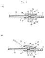
- Fig. 4(a) is a cross-sectional view showing the structure of the window glass 11 for an automobile
- Fig. 4(b) is an illustration showing operations to remove a resin holder 15.
- the same reference numerals as in the first embodiment designate the same parts, and accordingly, description of these parts is omitted.
- a recessed concave portion 13 is formed, instead of the through hole, in the glass plate 12.
- the concave portion 13 is formed in both surfaces of the glass plate 12. However, it may be formed only one surface when there is no problem of strength.
- the concave portion 13 corresponds to the opening referred to in the present invention.
- a notch 16 is formed in an upper end portion of the resin holder 15 in an elevating direction at the position facing the glass plate 12.
- the presence of the notch 16 provides a space K between the surface of the glass plate 12 and the tip portion of the resin holder 15.
- the space K is determined to have a size which allows insertion of the tip end of a flat-ended screw driver 17.
- a groove 18 having a V-like shape in cross section is formed in an outer surface of the resin holder 15, in particular, at the position facing a surface of the glass plate 12.
- the resin holder 15 integrally with the glass plate so that a portion of the resin holder 15 fills the concave portion 13, the resin holder 15 can be fixed to the glass plate 12. Namely, the coming-off of the resin holder 15 from the glass plate 12 can be prevented by the engagement of an engaging portion 14, formed in the concave portion 13, with the peripheral wall of the concave portion 13.
- the resin holder 15 can be removed from the glass plate 12 with use of the screw driver 17 as shown in Fig. 4(b). Specifically, by inserting the tip end of the screw driver 17 into the space K and applying a force to the screw driver 17 so that the tip portion of the screw driver 17 is apart from the surface of the glass plate 12, a clamping portion 19 of the resin holder 15 is deformed elastically to provide a state that the clamping portion 19 is apart from the surface of the glass plate 12.
- the clamping portion 19 can be deformed elastically with a relatively weak operating force since a V-letter like groove 18 is formed in an outer surface of the claming portion 19, and the engaging portion 14 formed integrally with the clamping portion 19 can be drawn out from the concave portion 13.
- the resin holder 15 can be drawn out from the glass plate 12 without breaking the glass plate 12.
- Fig. 5 is a perspective view showing the structure of the window glass 21 for an automobile
- Fig. 6 is a cross-sectional view showing the structure of the window glass 21 for an automobile.
- the window glass 21 for an automobile comprises a glass plate 22 and a resin holder 24 formed in a peripheral portion 23 of the glass plate 22 in the same manner as the first embodiment.
- the glass plate 22 is provided with a projection 25 projecting toward a front surface side.
- the diameter of the projection 25 is preferably about 5 to 10 mm. In this embodiment, the diameter of the projection 25 is determined to be 8 mm.
- the projection 25 is provided at both surfaces of the glass plate 22. However, it may be provided only one surface when there is no problem of strength.
- the resin holder 24 is formed integrally with the glass plate 22 by injection molding.
- the resin holder 24 comprises mainly two clamping portions 26 for holding the glass plate 22 in a clamping state, a connecting portion 27 for connecting the two clamping portions 26 and a mounting portion 28 extending from a lower face of the connecting portion 27 and attached to an elevating rail 43.
- an engaging hole 29 is formed in the presence of the projections 25.
- the resin holder 24 is formed by disposing molding dies (not shown) having a cavity of predetermined shape so as to surround the projections 25; injecting a molten resin material into the molding dies and curing the resin material by cooling. By injection-molding the resin material, the resin holder 24 is formed in such a state that the resin holder clamps the glass plate 22 and is engaged with the projections 25. Namely, the coming-off of the resin holder 24 from the glass plate 22 can be prevented in such state that the peripheral wall of engaging holes 29 formed in the resin holder 24 is engaged with the peripheral wall of the projections 25.
- Fig. 7 is a perspective view showing the structure of the window glass 31 for an automobile
- Fig. 8 is a cross-sectional view showing the structure of the window glass 31 for an automobile.
- the same reference numerals designate the same parts in the first embodiment, and explanation of these parts is omitted.
- a curved notch 35 is formed in a glass plate 32.
- a resin holder 34 can be fixed to the glass plate 32 by forming the resin holder integrally with the glass plate by injection molding at a peripheral portion of the glass plate 32 so that a portion of the resin holder 34 fills the notch 35. Namely, an engaging portion 36 formed in the cavity of the notch 35 is engaged with the peripheral wall of the curved notch 35, whereby the resin holder 34 is prevented from coming-off from the glass plate 32.
- the present invention is not restricted to these embodiments but various improvements and design changes are possible as far as those are not deviated from the spirit of the present invention.
- the first embodiment shows that a single through hole 5 is formed in a single resin holder 4
- two or more through holes may be formed.
- the through hole 5 is shown to have a circular shape, it may be such one having an elongated or polygonal shape.
- the fourth embodiment shows the notch 35 which penetrates the glass plate 32.
- the notch may be a concave as in the second embodiment.
- a combination of the opening or aperture or the projection and the shape of the resin holder is optional.
- the glass plate used in the present invention may be of tempered glass, laminated glass, multi-layer glass formed by laminating a transparent resin layer on a single glass plate, organic glass composed of a transparent resin material or the like.
- the window glass for an automobile according to the present invention can be used together with various types of elevating device such as a wire type regulator or an arm type regulator as shown in Fig. 9.
- the opening or aperture in the glass plate As described in the first, second or fourth embodiment.
- the resin holder can easily be broken by inserting a tool such as a drill into the concave portion to remove the resin holder from the glass plate, whereby the glass plate can be recycled in order to save resources.
- the concave portion can be used as a target for inserting the tool, and insertion of the tool into the through hole of the glass plate can be easy, whereby there is little possibility of breaking the glass plate.
- the diameter length (hereinbelow, it may be referred to simply as the aperture size, which is represented by "a") of the through hole in a direction substantially parallel to a side edge of the glass plate is preferably 2 to 10 mm, in particular, 3 to 8 mm (8 mm in the first embodiment).
- a is 2 mm or more because a force applied to the resin holder by the elevating device in the elevation of the glass plate is not more than 1000N. Contrary, when “a” is too large, the diameter length in a direction perpendicular to the side edge of the glass plate is inevitably large whereby it is necessary to increase the area for clamping the resin holder to the glass plate. Accordingly, the dimension of the glass plate becomes large, and the stroke for elevating the glass plate becomes small. Accordingly, it is preferable that "a” is 10 mm or less.
- the length from the position of the through hole, which is the nearest to a side edge of the glass plate to the side edge of the glass plate (hereinbelow, it may be referred to simply as the distance from the side edge of the glass plate to the opening, which is represented by "b") is preferably thicker than the thickness of the glass plate but not more than 5 times as much as the thickness of the glass plate.
- "b" is determined to be larger than the thickness of the glass plate, the breakage of the glass plate due to a resin pressure at the injection molding can be prevented.
- the diameter length in a direction perpendicular to the side edge of the glass plate is inevitably large, and it is necessary to increase the space for clamping the resin holder to the glass plate. Accordingly, the dimension of the glass plate becomes large, and the stroke for elevating the glass plate becomes small. Therefore, it is preferable that "b" is not more than 5 times as much as the thickness of the glass plate.
- the length of a side portion (the connecting portion) (the length is referred to as "c") of the resin holder, which is in contact with the side edge of the glass plate is 5 to 100 mm.
- “c” is determined to be 5 mm or more, the area of contact between the side portion and the side edge of the glass plate can sufficiently be maintained, and the rotation of the resin holder around the through hole as a rotation axis can be prevented.
- the value of "c” is larger than the value of "a” from the viewpoints of the retention of the shape of the resin holder and the stability of molding in the injection molding.
- the window glass indicated a high strength to a force (referred to as F A , which will be described in detail in the following) produced when the resin holder was pulled in a direction parallel to the surface of the glass plate (the direction separating from the glass plate), and when "b" had a smaller value, the window glass indicated a high strength to a force (referred to as F B , which will be described in detail in the following) produced when the resin holder was pushed in a direction perpendicular to the surface of the glass plate.
- F A a high strength to a force
- F B a high strength to a force
- the area s of a region S surrounded by vertical lines (L 1 , L 2 ) extended from both ends (P 1 , P 2 ) of the through hole 5 in a direction substantially parallel to a side edge e of the glass plate 2 to the side edge e, a peripheral edge C of the through hole 5 at a side edge e and the side edge e, is 20 to 180 mm 2 , more preferably, 40 to 150 mm 2 , particularly, 60 to 130 mm 2 (Fig. 11).
- the strength of the window glass for an automobile to a force produced when the resin holder is pulled in direction parallel to the surface of the glass plate can be increased.
- s is determined to be 180 mm 2 or less, particularly, 150 mm 2 or less, more particularly, 130 mm 2 or less
- the strength of the window glass for an automobile to a force produced when the resin holder is pushed in a direction perpendicular to the surface of the glass plate can be increased.
- the direction parallel to or perpendicular to the surface of the glass plate means the direction parallel to or perpendicular to the surface of the mounting portion (reference numeral 9 in Fig. 1) of the resin holder, which has a negligible degree of curve in comparison with the degree of curve of the surface of the glass plate.
- Glass plates with a resin holder having the shape as shown in Fig. 3, which was formed integrally therewith were prepared.
- the length (c) of the side portion (the connecting portion) of the resin holder, which was in contact with a side edge of the glass plates, was 30 mm.
- a peripheral portion of each glass plate was set in molding dies having a cavity corresponding to the shape of the resin holder, and a resin material of polyoxymethylene containing 25% of glass fibers was injected into the cavity followed by curing.
- the glass plates used were flat plate type glass plates each having dimensions of 500 (mm) ⁇ 600 (mm) and a thickness of 3.5 mm. In each glass plate, a through hole as indicated in Table 1 was formed.
- a indicates the diameter length of the through hole in a direction substantially parallel to the side edge of the glass plate
- b indicates the length from the position of the through hole which is the nearest to the side edge of the glass plate to the side edge of the glass plate.
- the strength test A is as follows. Each glass plate is supported by a supporting tool 81 in a vertical direction with the resin holder 4 being directed upside, by fixing a peripheral portion of the glass plate, which is at the side opposite to the side where the resin holder 4 is formed integrally. A hook 82 is inserted into the aperture 10 formed in the mounting portion 9. A pulling force is applied to a load cell 80 connected to the hook 82 in a direction along the surface of the glass plate 2 and perpendicular to the side edge covered with the resin holder 4. The magnitude F A (N) of the pulling force produced when the glass plate 2 is broken by the pulling force is measured by the load cell 80 to obtain a result of the strength test A.
- the strength test B is as follows.
- the glass plate 2 is placed on a supporting table 83 so that the surface of the glass plate 2 is supported horizontally.
- a portion of the glass plate 2, in the vicinity of the resin holder 4, is clamped together with the supporting surface of the supporting table 83 with a clamping member 84a and a clamping member 84b so as to be fixed.
- a load cell 80 is brought to contact with the mounting portion 9 aiming the aperture 10 as a target, and a pushing force is applied thereto by the load cell 80 in a direction perpendicular to the surface of the glass plate 2.
- the magnitude F B (N) of the pushing force produced when the glass plate 2 is broken by the pushing force is measured by the load cell 80 to obtain a result of the strength test B.
- Fig. 12(a) the ordinate represents the averaged value F A (unit: N) of measurement results of forces in the strength test A and the abscissa represents the aperture size a (unit: mm).
- Fig. 12(b) the ordinate represents the averaged value F B (unit: N) of the measurement results of forces in the strength test B and the abscissa represents the aperture size a (unit: mm).
- Fig. 13(a) the ordinate represents the averaged value F A (unit: N) of the measurement results of forces in the strength test A
- b (unit: mm) represents the distance from the side edge of the glass plate to the opening.
- the ordinate represents the averaged value F B (unit: N) of the measurement results of forces in the strength test B, and b (unit: mm) represents the distance from the glass plate to the opening.
- the ordinate represents the averaged value F A (unit: N) of the measurement results of forces in the strength test A, and the abscissa represents the area s (unit: mm 2 ) of the region S.
- the ordinate represents the averaged value F B (unit: N) of the measurement results of forces in the strength test B and the abscissa represents the area s (unit: mm 2 ) of the region S.
- Fig. 12(a) it is found that as the aperture size is large, it is possible to obtain a reaction to a force of pulling the resin holder in a direction parallel to the surface of the glass plate (the direction separating from the glass plate).
- Fig. 12(b) it is found that as the aperture size is small, it is possible to obtain a reaction to a pushing force from a direction perpendicular to the surface of the glass plate.
- the aperture size is determined to be 6.8 mm or more under the condition that the distance from the side edge of the glass plate to the opening is 11 to 15 mm, there is no possibility that the resin holder comes off from the glass plate even though the resin holder is pulled in a direction parallel to the surface of the glass plate with a force of 2500N or more, and the breakage of the glass plate or the resin holder can be prevented. Further, when the aperture size is to be 2 mm or more, there can be considered that the resin holder does not come off from the glass plate even though the resin holder is pulled with a force of about 1000N which would be applied in the elevation of the window glass for an automobile.
- the aperture size is determined to be 8.8 mm or less under the condition that the distance from the side edge of the glass plate to the opening is 11 to 15 mm, the breakage of the glass plate or the resin holder can be prevented even though the resin holder is pushed in a direction perpendicular to the surface of the glass plate with a force of 500N or more.
- the aperture size is to be 10 mm or less under the condition that the distance from the side edge of the glass plate to the opening is 13 mm or less, there can be considered that the breakage of the glass plate or the resin holder can be prevented even though the resin holder is pushed in a direction perpendicular to the surface of the glass plate with a force of 500N or more.
- Fig. 13(a) it is found that as the distance from the side edge of the glass plate to the opening is large, it is possible to obtain a reaction to a force pulling the resin holder in a direction parallel to the surface of the glass plate (the direction separating from the glass plate).
- Fig. 13(b) it is found that as the distance from the side edge of the glass plate to the opening is small, it is possible to obtain a reaction to a pushing force in a direction perpendicular to the surface of the glass plate.
- the distance from the side edge of the glass plate to the opening is determined to be 11 mm or more under the condition that the aperture size is 6.8 to 8.8 mm, there is little possibility that the resin holder comes off from the glass plate even though the resin holder is pulled in a direction parallel to the surface of the glass plate with a force of 2500N or more, and the breakage of the glass plate or the resin holder can be prevented.
- the breakage of the glass plate or the resin holder can be prevented even though the resin holder is pushed in a direction perpendicular to the surface of the glass plate with a force of 500N or more.
- Fig. 14(a) it is found that as the area of the region S is large, it is possible to obtain a reaction to a force of pulling the resin holder in a direction parallel to the surface of the glass plate (the direction separating from the glass plate). As shown in Fig. 14(b), it is found that as the region S is small, it is possible to obtain a reaction to a pushing force in a direction perpendicular to the surface of the glass plate.
- the area of the region S is determined to be 80 mm 2 or more, there is little possibility that the resin holder comes off from the glass plate even though the resin holder is pulled in a direction parallel to the surface of the glass plate with a force of 2500N or more, and the breakage of the glass plate or the resin holder can be prevented.
- the breakage of the glass plate or the resin holder can be prevented even though the resin holder is pushed in a direction perpendicular to the surface of the glass plate with a force of 600N or more.
- the breakage of the glass plate or the resin holder can be prevented even though the resin holder is pushed in a direction perpendicular to the surface of the glass plate with a force of 500N or more when the area of the region S is 180 mm 2 or less, or with a force of 600N or more when the area of the region S is 150 mm 2 or less respectively.
- a primer application process or a bonding process with use of an adhesive is unnecessary since the resin holder is formed integrally with the glass plate having an opening or aperture, or a projection by injection-molding a resin material. Accordingly, it is possible to produce a window glass for an automobile having the resin holder in a relatively short time. In this case, the breakage of the glass plate or the resin holder in use for an automobile window can be prevented by forming the opening, aperture or the projection in the glass plate at a predetermined position or with a predetermined shape. Further, the size of the resin holder can be reduced whereby the weight of the window glass for an automobile can be reduced as a whole.
- the glass plate for an automobile window can effectively be utilized as recycled resources and can be regenerated as glass.
Landscapes
- Engineering & Computer Science (AREA)
- Mechanical Engineering (AREA)
- Window Of Vehicle (AREA)
- Injection Moulding Of Plastics Or The Like (AREA)
Abstract
A window glass for an automobile, comprising a glass
plate in which a through hole is formed in its peripheral
portion and a resin holder which is formed integrally
with the glass plate so as to fill the through hole and
which clamps the glass plate, is presented. The window
glass for an automobile can be produced in a relatively
short time; can reduce the size of the holder and allows
resource recycling of the window glass.
Description
The present invention relates to a window glass for
an automobile having a holder connectable to an elevating
device and a glass recycling method for regenerating the
glass plate for a window glass for an automobile.
A door for an automobile is provided with a window
glass capable of being opened and closed and an elevating
device for elevating the window glass. The elevating
device includes so-called arm type regulator and wire
type regulator. Fig. 9 shows an example of the elevating
device called the arm type regulator. An elevating
device 40 comprises two arms 41, 42, an elevating rail
43, a fixed rail 44, a regulator (not shown) and so on.
In more detail, the two arms 41, 42 are connected by a
shaft as a fulcrum point 46 around which they are rotated
each other. Upper ends of arms 41, 42 are attached to
the elevating rail 43 so as to be capable of sliding. A
lower end of an arm 41 is attached to the fixed rail 44
so as to be capable of sliding, and a lower end of an arm
42 is connected to the main body of a regulator (not
shown) by means of a gear wheel 47. Namely, the gear
wheel 47 is driven by the regulator whereby the elevating
rail 43 is moved upward.
A glass plate 48 is connected to the elevating rail
43 by means of two holders 49. The holders 49 are made
of polyacetal resin including glass fibers and are bonded
to positions in the vicinity of a lower side of the glass
plate by using a urethane adhesive after primer has been
coated on the glass plate 48 and the holders 49.
In the structure described above, the primer had to
be applied to the glass plate 48 and the holders 49 in
order to assure the bonding strength of the holders 49.
For this, a primer application process and a drying
process were needed, and it took a relatively long time
until the adhesive was cured. Further, in order to
assure the bonding strength, a sufficient area of contact
between the holders 49 and the glass plate 48 had to be
provided. This affected an increase of the size and
weight of the holders 49.
JP-Y-4-22989 publication (referred to as '989
publication) discloses that a resin holder is formed
integrally with a peripheral portion of a glass plate by
injection molding. According to the '989 publication,
the above-mentioned problem can be solved because the
resin holder is formed integrally with the peripheral
portion of the glass plate by injection molding.
However, since the bonding area of the resin holder
to the glass plate is small, the bonding strength of the
resin holder to the glass plate is small. In particular,
the resin holder is applied with a force in a direction
of coming-off from the glass plate due to a force from
the elevating device because an elevating direction of
the glass plate by the elevating device is substantially
coincidence with the direction of the surface of the
glass plate. Accordingly, it is undesirable that the
bonding strength of the resin holder to the glass plate
is small.
Accordingly, it is considered to apply a primer
treatment and an appropriate adhesive to the glass plate
when the resin holder is formed integrally with the
peripheral portion of the glass plate by injection
molding. However, such primer treatment and the
application of an adhesive cause the following
disadvantage.
Namely, from the viewpoint of recycling resources in
recent years, the recycling of glass plates for
automobile windows is expected. If primer or an adhesive
adheres on a glass plate, it is difficult to separate
glass from these materials. Accordingly, the used window
glass has to be scrapped. Such disadvantage occurs
similarly even in a case of the resin holder formed
integrally by injection molding.
Further, a window glass to which a water-repellent
treatment is conducted to a surface of the glass plate is
sometimes used in recent years. When the water-repellent
treatment is conducted to the glass plate, there causes
difficulty in the adhering of primer or an adhesive on
the glass plate. Accordingly, when the water-repellent
treatment is conducted to the glass plate, masking has to
be conducted to the glass plate at the position where the
resin holder is to be bonded.
In view of the above-mentioned circumstances, it is
an object of the present invention to provide a window
glass for an automobile, which can be produced in a
relatively short time while use of primer or an adhesive
is unnecessary; can reduce the size of a holder and
allows resource recycling for the window glass, and a
glass recycling method for regenerating the glass plate
of a window glass for an automobile.
In accordance with the present invention, there is
provided a window glass for an automobile comprising a
glass plate for an automobile and a resin holder for
connecting the glass plate to an elevating device for
elevating the glass plate wherein the glass plate is
capable of being elevated by means of the elevating
device, the window glass for an automobile being
characterized in that an opening or aperture is formed in
a peripheral portion of the glass plate and the resin
holder is formed integrally with the peripheral portion
including the opening or aperture of the glass plate by
injection molding.
Further, in accordance with the present invention,
there is provided a window glass for an automobile
comprising a glass plate for an automobile and a resin
holder for connecting the glass plate to an elevating
device for elevating the glass plate wherein the glass
plate is capable of being elevated by means of the
elevating device, the window glass for an automobile
being characterized in that a projection is formed in a
peripheral portion of at least one of glass plate
surfaces and the resin holder is formed integrally with
the peripheral portion including the projection of the
glass plate by injection molding.
As described above, according to the window glass
for an automobile of the present invention, the opening
or aperture or a projection is formed in a peripheral
portion of the glass plate at a position where the resin
holder is formed. Then, the resin holder is formed
integrally with the glass plate by injection molding. In
more detail, the peripheral portion of the glass plate
including the opening or aperture or the projection is
clamped by molding dies in which an engraved portion
corresponding to the shape of the resin holder is formed.
A cavity is formed around the peripheral portion of the
glass plate in association with the molding dies. A
resin material is injected into the cavity and the
injected material is solidified whereby the resin holder
is formed so as to clamp the peripheral portion of the
glass plate. The opening means a portion opened in a
surface of the glass plate, such as a recess from the
glass plane, a curved notch or the like, and the aperture
means a through hole.
When the opening or aperture is formed in the
peripheral portion of the glass plate, the resin portion
filling the opening or aperture, i.e., a portion of the
resin holder constitutes an engaging portion to the
peripheral wall of the opening or aperture. Accordingly,
the coming-off of the resin holder from the glass plate
can be prevented. Further, even in a case that the
projection is formed in the peripheral portion of the
glass plate, a portion of the resin holder constitutes an
engaging portion to the peripheral surface of the
projection. Accordingly, the coming-off of the resin
holder from the glass plate can be prevented. Further,
since the opening or aperture or the projection formed in
the glass plate is engaged with the resin holder, a
sufficient bonding strength between the glass plate and
the resin holder can be assured even when a water-repellent
treatment is conducted to the glass plate.
In the thus obtained window glass for an automobile,
the resin holder can be fixed to the glass plate by
injection-molding a resin material. Accordingly, a
primer application process to the glass plate or a
bonding process with use of an adhesive is unnecessary.
Accordingly, a window glass for an automobile can be
produced in a relatively short time. Further, since no
adhesive is used, the glass plate can certainly be
separated from the resin holder, and the glass plate can
be effectively used as resources to be recycled. Namely,
a state that no resin component is attached to the glass
plate can easily be realized by deforming or destroying
the resin holder to cancel an engaging state of the resin
holder to the opening or aperture or the projection of
the glass plate. Then, the glass plate from which the
resin holder is removed is broken into appropriate pieces
as the case requires, and glass pieces are put into a
glass melting furnace for producing glass plates to
regenerate glass.
In the present invention described above, it is
preferable that a notch is formed in an upper end portion
of the resin holder at a side facing the glass plate so
that a space is formed between the surface of the glass
plate and the resin holder at an upper end side of the
resin holder in an elevating direction of the resin
holder. The size of this notch is determined to be, for
example, a size permitting insertion of the tip portion
of a tool such as a screw driver.
The provision of the space between the surface of
the glass plate and the upper end portion of the resin
holder can realize the following treatment. When the tip
of a tool such as a screw driver is inserted into the
space and a force is applied to the screw driver so that
the tip portion of the screw driver leaves from the
surface of the glass plate, the resin holder is
elastically deformed to show a state that the holder is
separated from the surface of the glass plate. Namely,
the resin holder is deformed so as to cancel an engaging
state to the glass plate. Accordingly, when the exchange
of the resin holder attached to a glass plate is
desirable, the above-mentioned operation should be
carried out, whereby the resin holder can be removed
without breaking the glass plate. Thus, it is possible
to repair the elevating device without breaking the glass
plate if the elevating device is damaged. Further, when
an automobile is to be scrapped, the resin portion can be
separated from the glass plate without breaking the glass
plate so as to recover the glass plate. The recovered
glass plate can be broken into pieces of appropriate size
if necessary, and the pieces can be regenerated by
putting them into a glass melting furnace for producing
glass sheets.
In the following, several embodiments of the present
invention will be described in detail with reference to
drawing.
Fig. 1 is a perspective view showing the structure
of the window glass 1 for an automobile according to a
first embodiment of the present invention, and Fig. 2 is
a cross-sectional view showing the structure of the
window glass 1 for an automobile. Fig. 1(a) shows a
state before a resin holder 4 is formed and Fig. 1(b)
shows a state after the resin holder 4 is formed. The
window glass 1 for an automobile comprises a glass plate
2 and a resin holder 4 formed in a peripheral portion 3
(a lower edge portion in an elevating direction) of the
glass plate 2 as shown in Fig. 1(b).
The glass plate 2 is assembled in an automobile
door. The glass plate 2 is elevated by, for example, an
elevating device 40 as shown in Fig. 9. As shown in Fig.
1(a), a through hole 5 is formed in the peripheral
portion 3 of the glass plate 2, at which the resin holder
4 is formed, so as to penetrate the glass plate 2.
The resin holder 4 is formed integrally with the
peripheral portion 3 including the through hole 5 of the
glass plate 2 by injection molding. The resin holder 4
comprises mainly two clamping portions 6 for supporting
the glass plate 2 in a state that they clamp a peripheral
edge portion of the glass plate 2, a connecting portion 7
formed along an outer periphery of the glass plate 2 to
connect the two clamping portions 6, an engaging portion
8 formed to penetrate the through hole 5 of the glass
plate 2 so as to connect the two clamping portions 6 and
a mounting portion 9 expending from a lower face of the
connecting portion 7 to be attached to an elevating rail
43 (Fig. 9). An aperture 10 is formed in the mounting
portion 9 to permit the insertion of a fastening means
such as a bolt. Two resin holders 4 are provided in a
single glass plate 2 wherein the aperture 10 of one resin
holder 4 is formed to have a round shape and the aperture
10 of the other resin holder 4 is formed to have an
elongated shape.
The resin holder 4 is formed by disposing molding
dies (not shown) having a cavity of predetermined shape
so as to surround the through hole 5 of the glass plate
2; injecting a molten resin material such as polyacetal
resin into the molding dies and curing the resin material
by cooling.
By injection-molding the resin material, the resin
material fills the through hole 5, and the resin holder 4
is formed in such a shape that the glass plate 2 is
clamped by the clamping portions 6 and the connecting
portion 7. Namely, the resin portion filling the through
hole 5, i.e., the engaging portion 8 is engaged with the
peripheral wall of the through hole 5. In particular,
since the two clamping portions 6 are connected with the
engaging portion 8, there is no possibility that the
resin holder 4 comes off from the glass plate 2 unless
the resin holder 4 is destroyed. Further, since the
resin holder 4 is formed in such a state that the inner
surface of the connecting portion 7 is in contact with a
peripheral edge of the glass plate 2, there is no
possibility that the resin holder rotates around the
through hole 5 as the center.
In the window glass 1 for an automobile, the resin
holder 4 can be fixed to the glass plate 2 without
requiring other than the injection-molding of the resin
holder 4 to the glass plate 2. Therefore, a primer
application process and a bonding process with use of an
adhesive are unnecessary. Accordingly, the window glass
1 for an automobile with the resin holder 4 can be
produced in a relatively short time. Further, since no
adhesive agent is used, the resin holder 4 can certainly
be separated from the glass plate 2, and the glass plate
2 can effectively be used as resources to be recycled.
In addition, since the resin holder 4 is fixed to the
glass plate by being engaged with the peripheral wall of
the through hole 5, there is no need to assure the
bonding area as required in the conventional technique.
Accordingly, the size of the resin holder 4 can be
reduced, hence, the weight of the window glass for an
automobile can be reduced as a whole. Further, since the
resin holder 4 is formed by injection molding, the shape
of the resin holder can be optional (for example, the
shape shown in Fig. 3). Further, a notch 16 and/or a
groove 18 may be formed in the resin holder 4 as
described in the second embodiment which will be
described Hereinbelow.
Next, the window glass 11 for an automobile
according to the second embodiment of the present
invention will be described with reference to Fig. 4.
Fig. 4(a) is a cross-sectional view showing the
structure of the window glass 11 for an automobile, and
Fig. 4(b) is an illustration showing operations to remove
a resin holder 15. In this embodiment, the same
reference numerals as in the first embodiment designate
the same parts, and accordingly, description of these
parts is omitted.
In the window glass 11 for an automobile, a recessed
concave portion 13 is formed, instead of the through
hole, in the glass plate 12. In Fig. 4(a), the concave
portion 13 is formed in both surfaces of the glass plate
12. However, it may be formed only one surface when
there is no problem of strength. The concave portion 13
corresponds to the opening referred to in the present
invention.
A notch 16 is formed in an upper end portion of the
resin holder 15 in an elevating direction at the position
facing the glass plate 12. The presence of the notch 16
provides a space K between the surface of the glass plate
12 and the tip portion of the resin holder 15. The space
K is determined to have a size which allows insertion of
the tip end of a flat-ended screw driver 17. In an outer
surface of the resin holder 15, in particular, at the
position facing a surface of the glass plate 12, a groove
18 having a V-like shape in cross section is formed.
Thus, by forming the resin holder 15 integrally with
the glass plate so that a portion of the resin holder 15
fills the concave portion 13, the resin holder 15 can be
fixed to the glass plate 12. Namely, the coming-off of
the resin holder 15 from the glass plate 12 can be
prevented by the engagement of an engaging portion 14,
formed in the concave portion 13, with the peripheral
wall of the concave portion 13.
Further, in the window glass 11 for an automobile in
this embodiment, since the space K is provided, the resin
holder 15 can be removed from the glass plate 12 with use
of the screw driver 17 as shown in Fig. 4(b).
Specifically, by inserting the tip end of the screw
driver 17 into the space K and applying a force to the
screw driver 17 so that the tip portion of the screw
driver 17 is apart from the surface of the glass plate
12, a clamping portion 19 of the resin holder 15 is
deformed elastically to provide a state that the clamping
portion 19 is apart from the surface of the glass plate
12.
In particular, the clamping portion 19 can be
deformed elastically with a relatively weak operating
force since a V-letter like groove 18 is formed in an
outer surface of the claming portion 19, and the engaging
portion 14 formed integrally with the clamping portion 19
can be drawn out from the concave portion 13. Thus, when
clamping portions 19 at both sides are respectively
deformed elastically to cancel the engaging condition to
concave portions 13, the resin holder 15 can be drawn out
from the glass plate 12 without breaking the glass plate
12.
Next, the window glass 21 for an automobile
according to the third embodiment of the present
invention will be described with reference to Figs. 5 and
6. Fig. 5 is a perspective view showing the structure of
the window glass 21 for an automobile and Fig. 6 is a
cross-sectional view showing the structure of the window
glass 21 for an automobile.
The window glass 21 for an automobile comprises a
glass plate 22 and a resin holder 24 formed in a
peripheral portion 23 of the glass plate 22 in the same
manner as the first embodiment. The glass plate 22 is
provided with a projection 25 projecting toward a front
surface side. The diameter of the projection 25 is
preferably about 5 to 10 mm. In this embodiment, the
diameter of the projection 25 is determined to be 8 mm.
In Fig. 5, the projection 25 is provided at both surfaces
of the glass plate 22. However, it may be provided only
one surface when there is no problem of strength.
The resin holder 24 is formed integrally with the
glass plate 22 by injection molding. The resin holder 24
comprises mainly two clamping portions 26 for holding the
glass plate 22 in a clamping state, a connecting portion
27 for connecting the two clamping portions 26 and a
mounting portion 28 extending from a lower face of the
connecting portion 27 and attached to an elevating rail
43. In each of the clamping portions 26, an engaging
hole 29 is formed in the presence of the projections 25.
The resin holder 24 is formed by disposing molding
dies (not shown) having a cavity of predetermined shape
so as to surround the projections 25; injecting a molten
resin material into the molding dies and curing the resin
material by cooling. By injection-molding the resin
material, the resin holder 24 is formed in such a state
that the resin holder clamps the glass plate 22 and is
engaged with the projections 25. Namely, the coming-off
of the resin holder 24 from the glass plate 22 can be
prevented in such state that the peripheral wall of
engaging holes 29 formed in the resin holder 24 is
engaged with the peripheral wall of the projections 25.
Next, the window glass 31 for an automobile
according to the fourth embodiment of the present
invention will be described with reference to Figs. 7 and
8. Fig. 7 is a perspective view showing the structure of
the window glass 31 for an automobile, and Fig. 8 is a
cross-sectional view showing the structure of the window
glass 31 for an automobile. The same reference numerals
designate the same parts in the first embodiment, and
explanation of these parts is omitted.
A curved notch 35 is formed in a glass plate 32. A
resin holder 34 can be fixed to the glass plate 32 by
forming the resin holder integrally with the glass plate
by injection molding at a peripheral portion of the glass
plate 32 so that a portion of the resin holder 34 fills
the notch 35. Namely, an engaging portion 36 formed in
the cavity of the notch 35 is engaged with the peripheral
wall of the curved notch 35, whereby the resin holder 34
is prevented from coming-off from the glass plate 32.
As described above, four preferable embodiments of
the present invention have been explained. However, the
present invention is not restricted to these embodiments
but various improvements and design changes are possible
as far as those are not deviated from the spirit of the
present invention. For example, although the first
embodiment shows that a single through hole 5 is formed
in a single resin holder 4, two or more through holes may
be formed. Further, although the through hole 5 is shown
to have a circular shape, it may be such one having an
elongated or polygonal shape. Further, the fourth
embodiment shows the notch 35 which penetrates the glass
plate 32. However, the notch may be a concave as in the
second embodiment. A combination of the opening or
aperture or the projection and the shape of the resin
holder (for example, the notch 16 or the groove 18 in the
second embodiment) is optional.
The glass plate used in the present invention may be
of tempered glass, laminated glass, multi-layer glass
formed by laminating a transparent resin layer on a
single glass plate, organic glass composed of a
transparent resin material or the like. The window glass
for an automobile according to the present invention can
be used together with various types of elevating device
such as a wire type regulator or an arm type regulator as
shown in Fig. 9.
It may be difficult to form the projection in the
glass plate in the manufacturing process for the glass
plate, as described in the third embodiment.
Accordingly, it is preferable to form the opening or
aperture in the glass plate as described in the first,
second or fourth embodiment. In particular, it is
preferable to form the through hole in the glass plate,
as shown in Fig. 2, because the coming-off of the resin
holder from the glass plate can be prevented due to the
fact that the two clamping portions 6 are connected by
the engaging portion 8. In the case of forming the
through hole in the glass plate, it is preferable to form
a concave portion in an outer surface of the resin holder
at the position corresponding to the through hole of the
glass plate. It is because the resin holder can easily
be broken by inserting a tool such as a drill into the
concave portion to remove the resin holder from the glass
plate, whereby the glass plate can be recycled in order
to save resources. In this case, the concave portion can
be used as a target for inserting the tool, and insertion
of the tool into the through hole of the glass plate can
be easy, whereby there is little possibility of breaking
the glass plate.
In forming the through hole in the glass plate, the
diameter length (hereinbelow, it may be referred to
simply as the aperture size, which is represented by "a")
of the through hole in a direction substantially parallel
to a side edge of the glass plate is preferably 2 to 10
mm, in particular, 3 to 8 mm (8 mm in the first
embodiment). By determining "a" to be 2 mm, in
particular, 3 mm or more, the coming-off of the resin
holder from the glass plate can be prevented even when
the resin holder is pulled in a direction separating from
the glass plate in an elevating direction of the glass
plate. When "a" is determined to be about 6 mm, there is
little possibility that the resin holder comes off from
the glass plate even when a pulling force of 3000N is
applied thereto. It is particularly preferable that "a"
is 2 mm or more because a force applied to the resin
holder by the elevating device in the elevation of the
glass plate is not more than 1000N. Contrary, when "a"
is too large, the diameter length in a direction
perpendicular to the side edge of the glass plate is
inevitably large whereby it is necessary to increase the
area for clamping the resin holder to the glass plate.
Accordingly, the dimension of the glass plate becomes
large, and the stroke for elevating the glass plate
becomes small. Accordingly, it is preferable that "a" is
10 mm or less.
The length from the position of the through hole,
which is the nearest to a side edge of the glass plate to
the side edge of the glass plate (hereinbelow, it may be
referred to simply as the distance from the side edge of
the glass plate to the opening, which is represented by
"b") is preferably thicker than the thickness of the
glass plate but not more than 5 times as much as the
thickness of the glass plate. When "b" is determined to
be larger than the thickness of the glass plate, the
breakage of the glass plate due to a resin pressure at
the injection molding can be prevented. When "b" is too
large, the diameter length in a direction perpendicular
to the side edge of the glass plate is inevitably large,
and it is necessary to increase the space for clamping
the resin holder to the glass plate. Accordingly, the
dimension of the glass plate becomes large, and the
stroke for elevating the glass plate becomes small.
Therefore, it is preferable that "b" is not more than 5
times as much as the thickness of the glass plate.
It is preferable that the length of a side portion
(the connecting portion) (the length is referred to as
"c") of the resin holder, which is in contact with the
side edge of the glass plate, is 5 to 100 mm. When "c"
is determined to be 5 mm or more, the area of contact
between the side portion and the side edge of the glass
plate can sufficiently be maintained, and the rotation of
the resin holder around the through hole as a rotation
axis can be prevented. In this case, it is preferable
that the value of "c" is larger than the value of "a"
from the viewpoints of the retention of the shape of the
resin holder and the stability of molding in the
injection molding.
From the strength test results as shown in the
following, it was found that when "a" or "b" had a larger
value, the window glass indicated a high strength to a
force (referred to as FA, which will be described in
detail in the following) produced when the resin holder
was pulled in a direction parallel to the surface of the
glass plate (the direction separating from the glass
plate), and when "b" had a smaller value, the window
glass indicated a high strength to a force (referred to
as FB, which will be described in detail in the
following) produced when the resin holder was pushed in a
direction perpendicular to the surface of the glass
plate. It is supposed that these facts indicate that the
region of the glass plate corresponding to a portion
where the through hole is formed, i.e., at an outer
periphery side in a direction along the surface of the
glass plate from the through hole influences the strength
against the force applied to the resin holder. Namely,
it is preferable that the area s of a region S surrounded
by vertical lines (L1, L2) extended from both ends (P1,
P2) of the through hole 5 in a direction substantially
parallel to a side edge e of the glass plate 2 to the
side edge e, a peripheral edge C of the through hole 5 at
a side edge e and the side edge e, is 20 to 180 mm2, more
preferably, 40 to 150 mm2, particularly, 60 to 130 mm2
(Fig. 11). When s is determined to be 20 mm2 or more,
particularly, 40 mm2 or more, more particularly, 60 mm2
or more, the strength of the window glass for an
automobile to a force produced when the resin holder is
pulled in direction parallel to the surface of the glass
plate can be increased. When s is determined to be 180
mm2 or less, particularly, 150 mm2 or less, more
particularly, 130 mm2 or less, the strength of the window
glass for an automobile to a force produced when the
resin holder is pushed in a direction perpendicular to
the surface of the glass plate can be increased.
Preferred values of "a", "b", "c" and "s" have been
described with respect to the embodiment wherein the
through hole. is formed in the glass plate. By the same
reason, it is preferable that the values of "a", "b", "c"
and "s" have the above-mentioned values respectively with
respect to the embodiments wherein the opening or the
projection is formed in the glass plate.
The expression of "substantially" parallel to a side
edge of the glass plate in this specification means as
follows. Side edges of a glass plate for an automobile
window generally have a curved line. The curvature of
this curved line is small as negligible (the curvature
radius is large) in comparison with the dimension of the
through hole (for example, the curvature of the through
hole). Accordingly, a side edge of the glass plate can
be considered to have a substantially straight line (a
finite straight line). Nevertheless, the term of
"substantially" is used since the side edge of the glass
plate is formed to have a curved line in a strict sense.
Thus, since the side edge of the glass plate can be
considered to be substantially straight, the term
"substantially" as an adjunct is omitted with respect to
the direction perpendicular to the side edge or the
vertical line extended to the side edge.
With respect to the direction of a force applied to
the resin holder, the expression of parallel to or
perpendicular to the surface of the glass plate is used.
Since a glass plate of window glass for an automobile is
generally curved, it is difficult to establish
universally the direction parallel to or perpendicular to
the surface of the glass plate. In this specification,
accordingly, the direction parallel to or perpendicular
to the surface of the glass plate means the direction
parallel to or perpendicular to the surface of the
mounting portion (reference numeral 9 in Fig. 1) of the
resin holder, which has a negligible degree of curve in
comparison with the degree of curve of the surface of the
glass plate.
Test results for verifying preferred values of the
above-mentioned "a", "b" and "s" are described in the
following.
Glass plates with a resin holder having the shape as
shown in Fig. 3, which was formed integrally therewith
were prepared. The length (c) of the side portion (the
connecting portion) of the resin holder, which was in
contact with a side edge of the glass plates, was 30 mm.
In the preparation, a peripheral portion of each glass
plate was set in molding dies having a cavity
corresponding to the shape of the resin holder, and a
resin material of polyoxymethylene containing 25% of
glass fibers was injected into the cavity followed by
curing. The glass plates used were flat plate type glass
plates each having dimensions of 500 (mm) × 600 (mm) and
a thickness of 3.5 mm. In each glass plate, a through
hole as indicated in Table 1 was formed. In Table 1, "a"
(mm) indicates the diameter length of the through hole in
a direction substantially parallel to the side edge of
the glass plate, and "b" (mm) indicates the length from
the position of the through hole which is the nearest to
the side edge of the glass plate to the side edge of the
glass plate.
Two strength tests A and B were conducted to the
prepared samples respectively. The strength test A is as
follows. Each glass plate is supported by a supporting
tool 81 in a vertical direction with the resin holder 4
being directed upside, by fixing a peripheral portion of
the glass plate, which is at the side opposite to the
side where the resin holder 4 is formed integrally. A
hook 82 is inserted into the aperture 10 formed in the
mounting portion 9. A pulling force is applied to a load
cell 80 connected to the hook 82 in a direction along the
surface of the glass plate 2 and perpendicular to the
side edge covered with the resin holder 4. The magnitude
FA (N) of the pulling force produced when the glass plate
2 is broken by the pulling force is measured by the load
cell 80 to obtain a result of the strength test A.
The strength test B is as follows. The glass plate 2
is placed on a supporting table 83 so that the surface of
the glass plate 2 is supported horizontally. A portion
of the glass plate 2, in the vicinity of the resin holder
4, is clamped together with the supporting surface of the
supporting table 83 with a clamping member 84a and a
clamping member 84b so as to be fixed. A load cell 80 is
brought to contact with the mounting portion 9 aiming the
aperture 10 as a target, and a pushing force is applied
thereto by the load cell 80 in a direction perpendicular
to the surface of the glass plate 2. The magnitude FB
(N) of the pushing force produced when the glass plate 2
is broken by the pushing force is measured by the load
cell 80 to obtain a result of the strength test B.
In the strength test A, 5 glass plates each having
the resin holder formed integrally were prepared and
measurement of strength was conducted to glass plates
respectively. In the strength test B, 10 glass plates
with the resin holder formed integrally were prepared and
measurement of the strength was conducted respectively.
Table 1 shows results of these measurements. In Table,
FA (unit: N) indicates results of the strength test A (an
averaged value of 5 glass plates) and FB (unit: N)
indicates results of the strength test B (an averaged
value of 10 glass plates). Each strength test was
carried out under ordinary temperature and moisture. The
condition of the strength test A is shown in Fig. 10(a)
and the condition of the strength test B is shown in Fig.
10(b).
| a (mm) | b (mm) | s (mm2) | FA (N) | FB (N) | |
| Ex. 1 | 6.8 | 11 | 80 | 2785 | 817 |
| Ex. 2 | 6.8 | 13 | 93 | 2857 | 810 |
| Ex. 3 | 6.8 | 15 | 107 | 2913 | 724 |
| Ex. 4 | 7.8 | 11 | 92 | 3161 | 824 |
| Ex. 5 | 7.8 | 13 | 108 | 3204 | 756 |
| Ex. 6 | 7.8 | 15 | 124 | 3468 | 650 |
| Ex. 7 | 8.8 | 13 | 123 | 3350 | 670 |
The results shown in Table 1 and the graphs shown in
Figs. 12 to 14 indicate the following fact. In Fig.
12(a), the ordinate represents the averaged value FA
(unit: N) of measurement results of forces in the
strength test A and the abscissa represents the aperture
size a (unit: mm). In Fig. 12(b), the ordinate
represents the averaged value FB (unit: N) of the
measurement results of forces in the strength test B and
the abscissa represents the aperture size a (unit: mm).
In Fig. 13(a), the ordinate represents the averaged value
FA (unit: N) of the measurement results of forces in the
strength test A, and b (unit: mm) represents the distance
from the side edge of the glass plate to the opening. In
Fig. 13(b), the ordinate represents the averaged value FB
(unit: N) of the measurement results of forces in the
strength test B, and b (unit: mm) represents the distance
from the glass plate to the opening. In Fig. 14(a), the
ordinate represents the averaged value FA (unit: N) of
the measurement results of forces in the strength test A,
and the abscissa represents the area s (unit: mm2) of the
region S. In Fig. 14(b), the ordinate represents the
averaged value FB (unit: N) of the measurement results of
forces in the strength test B and the abscissa represents
the area s (unit: mm2) of the region S.
As shown in Fig. 12(a), it is found that as the
aperture size is large, it is possible to obtain a
reaction to a force of pulling the resin holder in a
direction parallel to the surface of the glass plate (the
direction separating from the glass plate). As shown in
Fig. 12(b), it is found that as the aperture size is
small, it is possible to obtain a reaction to a pushing
force from a direction perpendicular to the surface of
the glass plate.
Specifically, when the aperture size is determined
to be 6.8 mm or more under the condition that the
distance from the side edge of the glass plate to the
opening is 11 to 15 mm, there is no possibility that the
resin holder comes off from the glass plate even though
the resin holder is pulled in a direction parallel to the
surface of the glass plate with a force of 2500N or more,
and the breakage of the glass plate or the resin holder
can be prevented. Further, when the aperture size is to
be 2 mm or more, there can be considered that the resin
holder does not come off from the glass plate even though
the resin holder is pulled with a force of about 1000N
which would be applied in the elevation of the window
glass for an automobile.
Further, when the aperture size is determined to be
8.8 mm or less under the condition that the distance from
the side edge of the glass plate to the opening is 11 to
15 mm, the breakage of the glass plate or the resin
holder can be prevented even though the resin holder is
pushed in a direction perpendicular to the surface of the
glass plate with a force of 500N or more. Further, when
the aperture size is to be 10 mm or less under the
condition that the distance from the side edge of the
glass plate to the opening is 13 mm or less, there can be
considered that the breakage of the glass plate or the
resin holder can be prevented even though the resin
holder is pushed in a direction perpendicular to the
surface of the glass plate with a force of 500N or more.
As shown in Fig. 13(a), it is found that as the
distance from the side edge of the glass plate to the
opening is large, it is possible to obtain a reaction to
a force pulling the resin holder in a direction parallel
to the surface of the glass plate (the direction
separating from the glass plate). As shown in Fig.
13(b), it is found that as the distance from the side
edge of the glass plate to the opening is small, it is
possible to obtain a reaction to a pushing force in a
direction perpendicular to the surface of the glass
plate.
Specifically, when the distance from the side edge
of the glass plate to the opening is determined to be 11
mm or more under the condition that the aperture size is
6.8 to 8.8 mm, there is little possibility that the resin
holder comes off from the glass plate even though the
resin holder is pulled in a direction parallel to the
surface of the glass plate with a force of 2500N or more,
and the breakage of the glass plate or the resin holder
can be prevented.
Further, when the distance from the side edge of the
glass plate to the opening is to be 15 mm or less under
the condition that the aperture size is 6.8 to 8.8 mm,
the breakage of the glass plate or the resin holder can
be prevented even though the resin holder is pushed in a
direction perpendicular to the surface of the glass plate
with a force of 500N or more. Further, when the distance
from the side edge of the glass plate to the opening is
determined to be not more than 5 times as much as the
thickness of the glass plate (=17.5 mm or less: the
thickness of the glass plate in this test is 3.5 mm)
under the condition that the aperture size is about 6.8
mm, there can be considered that the breakage of the
glass plate or the resin holder can be prevented even
though the resin holder is pushed in a direction
perpendicular to the surface of the glass plate with a
force of 500N or more.
As shown in Fig. 14(a), it is found that as the area
of the region S is large, it is possible to obtain a
reaction to a force of pulling the resin holder in a
direction parallel to the surface of the glass plate (the
direction separating from the glass plate). As shown in
Fig. 14(b), it is found that as the region S is small, it
is possible to obtain a reaction to a pushing force in a
direction perpendicular to the surface of the glass
plate.
Specifically, when the area of the region S is
determined to be 80 mm2 or more, there is little
possibility that the resin holder comes off from the
glass plate even though the resin holder is pulled in a
direction parallel to the surface of the glass plate with
a force of 2500N or more, and the breakage of the glass
plate or the resin holder can be prevented. Further,
there can be considered that even though the resin holder
is pulled in a direction parallel to the surface of the
glass plate with a force of 2000N or more when the area
of the region S is 20 mm2 or more, or with a force of
2500N or more when the area of the region S is 40 mm2 or
more respectively, there is little possibility that the
resin holder comes off from the glass plate, and the
breakage of the glass plate or the resin holder can be
prevented.
Further, when the area of the region S is determined
to be 125 mm2 or less, the breakage of the glass plate or
the resin holder can be prevented even though the resin
holder is pushed in a direction perpendicular to the
surface of the glass plate with a force of 600N or more.
In addition, there can be considered that the breakage of
the glass plate or the resin holder can be prevented even
though the resin holder is pushed in a direction
perpendicular to the surface of the glass plate with a
force of 500N or more when the area of the region S is
180 mm2 or less, or with a force of 600N or more when the
area of the region S is 150 mm2 or less respectively.
According to the present invention described above,
a primer application process or a bonding process with
use of an adhesive is unnecessary since the resin holder
is formed integrally with the glass plate having an
opening or aperture, or a projection by injection-molding
a resin material. Accordingly, it is possible to produce
a window glass for an automobile having the resin holder
in a relatively short time. In this case, the breakage
of the glass plate or the resin holder in use for an
automobile window can be prevented by forming the
opening, aperture or the projection in the glass plate at
a predetermined position or with a predetermined shape.
Further, the size of the resin holder can be reduced
whereby the weight of the window glass for an automobile
can be reduced as a whole.
In particular, since an engaging state is provided
between the opening or aperture or the projection of the
glass plate and the resin holder, the application of an
adhesive to the glass plate or the resin holder can be
eliminated. Accordingly, the resin holder can certainly
be separated from the glass plate, and a resin component
adhering on the glass plate after the resin holder is
removed can be minimized. Then, the glass plate from
which the resin holder is removed can be put in a glass
melting furnace after the glass plate is broken into
pieces of appropriate size. Thus, the glass plate for an
automobile window can effectively be utilized as recycled
resources and can be regenerated as glass.
Claims (10)
- A window glass for an automobile comprising a glass plate for an automobile and a resin holder for connecting the glass plate to an elevating device for elevating the glass plate wherein the glass plate is capable of being elevated by means of the elevating device, the window glass for an automobile being characterized in that:an opening or aperture is formed in a peripheral portion of the glass plate and the resin holder is formed integrally with the peripheral portion including the opening or aperture of the glass plate by injection molding.
- A window glass for an automobile comprising a glass plate for an automobile and a resin holder for connecting the glass plate to an elevating device for elevating the glass plate wherein the glass plate is capable of being elevated by means of the elevating device, the window glass for an automobile being characterized in that:a projection is formed in a peripheral portion of at least one of glass plate surfaces and the resin holder is formed integrally with the peripheral portion including the projection of the glass plate by injection molding.
- The window glass for an automobile according to Claim 1, wherein the diameter length of the opening or aperture in a direction substantially parallel to a side edge of the glass plate is 2 to 10 mm.
- The window glass for an automobile according to Claim 1 or 3, wherein the length from the position of the opening or aperture, which is the nearest to a side edge of the glass plate, to the side edge of the glass plate is not more than 5 times as much as the thickness of the glass plate.
- The window glass for an automobile according to Claim 1 or 3, wherein the length from the position of the opening or aperture, which is the nearest to a side edge of the glass plate, to the side edge of the glass plate is 5 to 20 mm.
- The window glass for an automobile according to Claim 1, 3, 4 or 5, wherein the length of a side portion of the resin holder, which is in contact with a side edge of the glass plate is 5 to 100 mm and is longer than the diameter length of the opening or aperture in a direction substantially parallel to the side edge of the glass plate.
- The window glass for an automobile according to Claim 1, 3, 4, 5 or 6, wherein the area of a region surrounded by vertical lines extended from both ends of the opening or aperture in a direction substantially parallel to a side edge of the glass plate, a peripheral edge, at a side of the side edge of the glass plate, of the opening or aperture and the side edge of the glass plate is 20 to 180 mm2.
- The window glass for an automobile according to Claim 1, 2, 3, 4, 5, 6 or 7, wherein a notch is formed in an upper end portion of the resin holder at a side facing the glass plate so that a space is formed between the surface of the glass plate and the resin holder at an upper end side of the resin holder in an elevating direction of resin holder.
- A recycling method for glass which comprises deforming or destroying a resin holder formed on the glass plate for an automobile described in Claims 1, 2, 3, 4, 5, 6, 7 or 8 to cancel an engaging state to the glass plate, removing the resin holder from the glass plate, and putting the glass plate, from which the resin holder is removed, into a glass melting furnace to regenerate glass.
- A recycling method for glass which comprises inserting a tool into a space formed between the surface of the glass plate and a resin holder of the window glass for an automobile described in Claim 8, deforming or destroying the resin holder to cancel an engaging state to the glass plate, removing the resin holder from the glass plate, and putting the glass plate, from which the resin holder is removed, into a glass melting furnace to regenerate glass.
Applications Claiming Priority (3)
| Application Number | Priority Date | Filing Date | Title |
|---|---|---|---|
| JP2001059100 | 2001-03-02 | ||
| JP2001059100 | 2001-03-02 | ||
| PCT/JP2002/001877 WO2002070293A1 (en) | 2001-03-02 | 2002-02-28 | Window glass for car and method of recycling the window glass |
Publications (2)
| Publication Number | Publication Date |
|---|---|
| EP1281546A1 true EP1281546A1 (en) | 2003-02-05 |
| EP1281546A4 EP1281546A4 (en) | 2003-06-04 |
Family
ID=18918720
Family Applications (1)
| Application Number | Title | Priority Date | Filing Date |
|---|---|---|---|
| EP02701649A Withdrawn EP1281546A4 (en) | 2001-03-02 | 2002-02-28 | GLASS GLASS FOR CAR AND METHOD FOR RECYCLING THIS GLASS GLASS |
Country Status (4)
| Country | Link |
|---|---|
| US (1) | US20030061765A1 (en) |
| EP (1) | EP1281546A4 (en) |
| JP (1) | JPWO2002070293A1 (en) |
| WO (1) | WO2002070293A1 (en) |
Cited By (1)
| Publication number | Priority date | Publication date | Assignee | Title |
|---|---|---|---|---|
| EP1659251B1 (en) * | 2003-08-26 | 2010-03-03 | Melchor Daumal Castellon | Fastening gripper for window panes in power window devices of motor vehicles |
Families Citing this family (6)
| Publication number | Priority date | Publication date | Assignee | Title |
|---|---|---|---|---|
| US7121924B2 (en) * | 2004-04-20 | 2006-10-17 | 3M Innovative Properties Company | Abrasive articles, and methods of making and using the same |
| US7126549B2 (en) * | 2004-12-29 | 2006-10-24 | Agc Automotive Americas R&D, Inc. | Slot coupling patch antenna |
| US20070006533A1 (en) * | 2005-07-11 | 2007-01-11 | Faurecia Interior Systems U.S.A., Inc. | Vehicle window lift plate |
| US7979136B2 (en) * | 2007-12-07 | 2011-07-12 | Roche Diagnostics Operation, Inc | Method and system for multi-device communication |
| US9522447B2 (en) | 2014-04-18 | 2016-12-20 | Hi-Lex Controls, Inc. | Automotive glass removal tool |
| CN113427982B (en) * | 2021-06-22 | 2022-07-19 | 福耀玻璃工业集团股份有限公司 | Vehicle window and vehicle |
Family Cites Families (20)
| Publication number | Priority date | Publication date | Assignee | Title |
|---|---|---|---|---|
| IT1144416B (en) * | 1981-07-22 | 1986-10-29 | Fiat Auto Spa | CONNECTION DEVICE BETWEEN THE CRYSTAL AND THE WINDOW REGULATOR IN THE PORTS OF THE VEHICLES |
| JPS61186619U (en) * | 1985-05-14 | 1986-11-20 | ||
| JPH0422988Y2 (en) * | 1986-06-27 | 1992-05-27 | ||
| US4943179A (en) * | 1986-06-27 | 1990-07-24 | Central Glass Company, Limited | Plate member arrangement |
| JPH0422987Y2 (en) * | 1986-06-27 | 1992-05-27 | ||
| JPH0290119U (en) * | 1988-12-28 | 1990-07-17 | ||
| JPH02179716A (en) * | 1988-12-29 | 1990-07-12 | Hashimoto Forming Ind Co Ltd | Manufacture of vertically moving window for automobile |
| JP2681305B2 (en) | 1990-05-18 | 1997-11-26 | 小糸工業株式会社 | Information display device |
| DE4228881A1 (en) * | 1992-08-29 | 1994-03-03 | Henniges Gummi | Vehicle bodywork window - has frame fitted around glass pane and easily removable for replacement of pane with U=shaped clamp components engaging pane and fixed to bodywork |
| US5515651A (en) * | 1993-08-02 | 1996-05-14 | Brose Fahrzeugteile Gmbh & Co. Kg | Device for fastening a window of a motor vehicle in the guide device of a window lifter |
| JP3273690B2 (en) * | 1994-03-24 | 2002-04-08 | 株式会社ニフコ | Glass holder |
| US5502926A (en) * | 1994-09-26 | 1996-04-02 | Chrysler Corporation | Vehicle door glass liftplate mounting arrangement |
| DE4437532C2 (en) * | 1994-10-20 | 1996-12-12 | Brose Fahrzeugteile | Device for connecting a window lifter to the sliding window pane of a motor vehicle |
| DE29503036U1 (en) * | 1995-02-23 | 1995-04-20 | Brose Fahrzeugteile Gmbh & Co Kg, 96450 Coburg | Device for connecting a window pane to a window regulator |
| JP3355863B2 (en) * | 1995-04-20 | 2002-12-09 | 株式会社ニフコ | Glass holder and method for mounting window glass using the glass holder |
| DE19653046A1 (en) * | 1996-12-19 | 1998-06-25 | Brose Fahrzeugteile | Device for fastening a sliding window pane of a motor vehicle to the guide device of a window lifter |
| DE19734995B4 (en) * | 1997-08-13 | 2004-03-25 | Kiekert Ag | Device for fastening a window pane, in particular the window pane of a motor vehicle door, to a pane carrier |
| DE19819910C1 (en) * | 1998-05-05 | 1999-06-17 | Brose Fahrzeugteile | Catch for connection of window glazing to lifter |
| JP2000108657A (en) * | 1998-10-05 | 2000-04-18 | Nippon Sheet Glass Co Ltd | Vehicle glass plate and vehicle glass window |
| US6494003B1 (en) * | 2000-03-24 | 2002-12-17 | Hori Glass Co., Ltd. | Vehicle window glass and method of producing the same |
-
2002
- 2002-02-28 EP EP02701649A patent/EP1281546A4/en not_active Withdrawn
- 2002-02-28 WO PCT/JP2002/001877 patent/WO2002070293A1/en not_active Ceased
- 2002-02-28 JP JP2002569438A patent/JPWO2002070293A1/en active Pending
- 2002-11-01 US US10/285,512 patent/US20030061765A1/en not_active Abandoned
Cited By (1)
| Publication number | Priority date | Publication date | Assignee | Title |
|---|---|---|---|---|
| EP1659251B1 (en) * | 2003-08-26 | 2010-03-03 | Melchor Daumal Castellon | Fastening gripper for window panes in power window devices of motor vehicles |
Also Published As
| Publication number | Publication date |
|---|---|
| US20030061765A1 (en) | 2003-04-03 |
| WO2002070293A1 (en) | 2002-09-12 |
| JPWO2002070293A1 (en) | 2004-07-02 |
| EP1281546A4 (en) | 2003-06-04 |
Similar Documents
| Publication | Publication Date | Title |
|---|---|---|
| US5398452A (en) | Screwed fixing of a retaining or fixing member to a laminated glazing | |
| US10688700B2 (en) | Molding tool and method for forming and back-injecting a bendable sheet | |
| EP1992510B1 (en) | Window glass holder for vehicle and method of manufacturing window assembly for vehicle using the same | |
| EP1950603A1 (en) | Tool for holding liquid crystal display optical sheet and chassis | |
| US8850760B2 (en) | Method and device for producing a window glazing equipped with a profiled strip comprising an insert, and window glazing obtained | |
| US20030061765A1 (en) | Window glass for an automobile and glass recycling method | |
| JPH08290717A (en) | Glass holder and window glass mounting method using glass holder | |
| US20100201054A1 (en) | Temporary protection device with a pivoting lock | |
| GB2149451A (en) | Method and apparatus for the preliminary and/or final mounting of a vehicle door | |
| KR20040058049A (en) | Method for producing a window glass for a vehicle provided with an ornamental braid and a window glass for a vehicle provided with an ornamental braid | |
| EP2253447A1 (en) | Metal mold for injection molding of framed glass and manufacturing method for framed glass | |
| BR0313500B1 (en) | "PROCESS FOR MANUFACTURING HEIGHT-SHIFT-TO-VEHICLE GLASS, AND HEIGHT-SHIFT-TO-VEHICLE GLASS". | |
| KR100363868B1 (en) | Window glass holder for automobiles | |
| EP2105771A1 (en) | Mechanical splice | |
| JPS6253220A (en) | Car window and manufacture thereof | |
| JP7550144B2 (en) | Apparatus and method for overmolding glazing and inserts, and inserts used therein - Patents.com | |
| JPH01178422A (en) | Manufacture of glass assembly | |
| US20240240504A1 (en) | Method for manufacturing a sliding glazing unit, and sliding glazing unit | |
| JP6307765B2 (en) | Mounting mechanism | |
| EP4219329A1 (en) | Transport pallet for pane retaining elements, method for transporting pane retaining elements, and method for assembling a pane retaining element and a windowpane | |
| JP2659767B2 (en) | Wind glass molding method | |
| JPH04107113A (en) | Method for jointing fiber-reinforced resin molded item | |
| JPH0321942Y2 (en) | ||
| EP1593801A2 (en) | Pin for locks for auto vehicles | |
| JPH02276605A (en) | Manufacture of window glass with frame |
Legal Events
| Date | Code | Title | Description |
|---|---|---|---|
| PUAI | Public reference made under article 153(3) epc to a published international application that has entered the european phase |
Free format text: ORIGINAL CODE: 0009012 |
|
| 17P | Request for examination filed |
Effective date: 20021128 |
|
| AK | Designated contracting states |
Designated state(s): AT BE CH CY DE DK ES FI FR GB GR IE IT LI LU MC NL PT SE TR |
|
| A4 | Supplementary search report drawn up and despatched |
Effective date: 20030425 |
|
| RIC1 | Information provided on ipc code assigned before grant |
Ipc: 7E 05F 11/38 B Ipc: 7B 60J 1/17 A |
|
| 17Q | First examination report despatched |
Effective date: 20030812 |
|
| STAA | Information on the status of an ep patent application or granted ep patent |
Free format text: STATUS: THE APPLICATION IS DEEMED TO BE WITHDRAWN |
|
| 18D | Application deemed to be withdrawn |
Effective date: 20050607 |