EP1281543A1 - Process for determining the air flow rate of a heating, ventilation and air conditioning unit of a motor vehicle - Google Patents
Process for determining the air flow rate of a heating, ventilation and air conditioning unit of a motor vehicle Download PDFInfo
- Publication number
- EP1281543A1 EP1281543A1 EP02017031A EP02017031A EP1281543A1 EP 1281543 A1 EP1281543 A1 EP 1281543A1 EP 02017031 A EP02017031 A EP 02017031A EP 02017031 A EP02017031 A EP 02017031A EP 1281543 A1 EP1281543 A1 EP 1281543A1
- Authority
- EP
- European Patent Office
- Prior art keywords
- motor
- unit
- flow rate
- voltage
- fan
- Prior art date
- Legal status (The legal status is an assumption and is not a legal conclusion. Google has not performed a legal analysis and makes no representation as to the accuracy of the status listed.)
- Granted
Links
Images

Classifications
-
- B—PERFORMING OPERATIONS; TRANSPORTING
- B60—VEHICLES IN GENERAL
- B60H—ARRANGEMENTS OF HEATING, COOLING, VENTILATING OR OTHER AIR-TREATING DEVICES SPECIALLY ADAPTED FOR PASSENGER OR GOODS SPACES OF VEHICLES
- B60H1/00—Heating, cooling or ventilating devices
- B60H1/00642—Control systems or circuits; Control members or indication devices for heating, cooling or ventilating devices
- B60H1/00735—Control systems or circuits characterised by their input, i.e. by the detection, measurement or calculation of particular conditions, e.g. signal treatment, dynamic models
- B60H1/00792—Arrangement of detectors
-
- B—PERFORMING OPERATIONS; TRANSPORTING
- B60—VEHICLES IN GENERAL
- B60H—ARRANGEMENTS OF HEATING, COOLING, VENTILATING OR OTHER AIR-TREATING DEVICES SPECIALLY ADAPTED FOR PASSENGER OR GOODS SPACES OF VEHICLES
- B60H1/00—Heating, cooling or ventilating devices
- B60H1/00642—Control systems or circuits; Control members or indication devices for heating, cooling or ventilating devices
- B60H1/00814—Control systems or circuits characterised by their output, for controlling particular components of the heating, cooling or ventilating installation
- B60H1/00821—Control systems or circuits characterised by their output, for controlling particular components of the heating, cooling or ventilating installation the components being ventilating, air admitting or air distributing devices
- B60H1/00828—Ventilators, e.g. speed control
Definitions
- the present invention relates to a process for determining the air flow rate of a heating, ventilation and air conditioning unit for the passenger compartment of a motor vehicle.
- the subject of the invention is a process for determining the air flow rate of a unit comprising:
- a climate control system including a heating, ventilation and air conditioning unit which typically comprises, as well as the said fan, heat exchangers for cooling and/or heating the air, ducts for conveying the air from outside and/or inside the passenger compartment to the fan, gates for modifying the path of the air through the unit and its distribution at the outlet, as well as actuators and electric motors for controlling the movement of the gates.
- a heating, ventilation and air conditioning unit typically comprises, as well as the said fan, heat exchangers for cooling and/or heating the air, ducts for conveying the air from outside and/or inside the passenger compartment to the fan, gates for modifying the path of the air through the unit and its distribution at the outlet, as well as actuators and electric motors for controlling the movement of the gates.
- Such units are connected to ducts intended to convey the treated air to the delivery outlets in the passenger compartment, typically formed in an orientable manner and with adjustable apertures.
- the air flow rate introduced into the passenger compartment by such a unit is determined with the so-called "body leakage” method: very briefly, with an air pressure sensor in the passenger compartment there is derived the curve which represents the static air pressure as a function of the air flow rate with the aid of a calibrated external blower which blows air into the passenger compartment at a known rate; this air flows through a flanged duct which is coupled to a window of the passenger compartment, the terminal flange of this duct being connected in a sealed manner to the aperture of this window.
- the characteristic curve of the fan of the motor vehicles unit is then subsequently derived, this time without the use of an external blower. From the intersection of the curves thus determined an indication of the rate of flow of air of the unit in the different operating conditions can be derived.
- the "body leakage" curve obtained is only and solely valid for the specific motor vehicle for which it has been derived, and for the configuration of the motor vehicle adopted in the measurement. It can however happen that, because of the intrinsic variations in production, the closures, the apertures, and the breathers can be different from one example to the other of the same model of motor vehicle. It can moreover happen that during running the user may alter the "leakage" conditions of the passenger compartment, for example simply by opening one or more of the windows of the passenger compartment to a greater or lesser extent.
- the measurement formed with the "body leakage” method is effected once and for all and does not take account of the speed of the motor vehicle. It does not, moreover, allow management in an easy manner of all the possible configurations for distribution of the air into the passenger compartment which the user or an automatic climate control system can select in use, nor does it take into account the effects of partial or total obstruction of one or more of the air delivery outlets by the user.
- the present invention therefore has the object of providing a process which allows determination of the air flow rate from a heating, ventilation and air conditioning unit in a manner which overcomes the above-described disadvantages of the prior art method.
- the method proposed by the invention is based on the specific characterisation of a unit, independently of the motor vehicle on which it will be utilised.
- this method does not require particularly complex or bulky apparatus, the detection of the flow rate being achievable with use of low cost sensors and being relatively lightly invasive. Moreover, it allows the determination of the flow rate in a manner which is not tied to the configuration of the unit, or the air distribution outlets into the passenger compartment or the motor vehicle in general, and is independent of the speed of the motor vehicle.
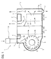
- the reference numeral 1 generally indicates a heating, ventilation and air conditioning unit for a motor vehicle.
- This unit comprises a support structure 2 in which are defined first and second inlets 3, 4 for air arriving in operation from outside and from within the passenger compartment of the motor vehicle respectively.
- the support structure or casing 2 of the unit 1 further has a plurality of outlets, such as those indicated 5, 6, and 7 for emitting air treated in the unit into the passenger compartment.
- the aperture 5 is intended to direct a stream of air towards the inner surface of the windscreen of the motor vehicle
- the aperture 6 is intended to be connected to a plurality of ventilation outlets at the mid height of the passenger compartment
- the aperture 7 is intended to direct a stream of treated air to the lower region of the passenger compartment.
- a further gate 8a makes it possible selectively to couple the inlet 3 for external air or the inlet 4 for internal air with a defined region 9 within the support casing 2, in which is disposed an electric fan 10 which comprises a bladed rotor 11 and an electric drive motor 12.
- the electric fan 12 when operated, is able to cause air to flow through the unit 1 form the inlet 3 or the inlet 4 to one or more of the outlets 5-7.
- the heat exchanger 13 is conveniently the evaporator of a refrigerating plant of type known per se.
- the heat exchanger 14 is conveniently of the liquid/air type, and is connected in the coolant liquid circuit of the internal combustion engine of the motor vehicle.
- the reference numeral 17 indicates in Figure 1 a further gate the position of which makes it possible to control the coupling of the outlets 5-7 with the evaporator 13 and the heater 14.
- a unit 1 of the type described above is disposed in a measurement station and subjected to a series of operations which will now be described.
- the gate 8a is caused to move to the position illustrated in Figure 1, in which it completely intercepts the inlet 4 for air coming from the interior of the passenger compartment (recirculation inlet).
- a calibrated flow rate measuring instrument such as that indicated 20 in Figure 1.
- the motor 12 of the fan 10 is supplied with a voltage having a first known value. If this motor is a DC motor intended in normal operation to be supplied with a DC voltage the value of which is adjustable by means of a rheostat, the motor 12 of the fan is connected in the measurement station to a DC supply source in the manner illustrated in Figure 2.
- the reference numeral 21 indicates a DC voltage generator which is coupled to the motor 12 of the electric fan via a rheostat 22 provided with a movable cursor 23.
- the motor 12 of the electric fan is initially supplied with a DC voltage of predetermined value lying in the range of normal variation of the voltage applied to this motor in normal operation on board a motor vehicle.
- the motor 12 initially has applied to it a voltage which by means of the rheostat 22 is regulated at 6 volts.
- the corresponding current consumed by the motor 12 of the electric fan is then measured, and by means of the instrument 20 the air flow rate which flows through the unit 1 is detected in a plurality of working conditions in which the outlet apertures 5-7 of the unit are for example initially all completely open, then at least one of them is partially closed, then at least one of them is totally closed, etc.
- the value of the voltage applied to the motor 12 of the fan is detected at the measurement station and memorised, as is the value of the corresponding current consumed by it, as well as the value of the air flow rate indicated by the flow rate measurement instrument 20.
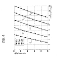
- the sets of three values (flow rate, current, voltage) thus obtained can be each represented with a point in a Cartesian diagram such as that shown in Figure 4.
- the values of air flow rate are plotted along the ordinate, for example in m 3 /h whilst the measured value of the current in the motor 12 of the electric fan is plotted along the abscissa, for example in amps.
- the sets of three values obtained as described above correspond for example to the points of the curve which in Figure 4 are indicated A, which refer to a particular supply voltage value applied to the motor 12 of the electric fan, for example equal to 6 volts.
- the curves A-E of Figure 4 represent the flow rate characteristics of the heating, ventilation and air conditioning unit 1 subjected to testing.
- the electric motor 12 of the fan of the unit is intended to be supplied in normal operation with a pulsed voltage of fixed frequency and modulated duration (pulse width modulation, PWM), and therefore its speed of rotation in operation is adjustable by varying the duty-cycle of the said voltage
- PWM pulse width modulation
- the duty-cycle of this voltage is for example detected at the measurement station as the value indicative of the average voltage supplied to the motor.
- the current flowing in the motor is also modulated, and its average value must be obtained at the measurement station.
- the electric motor 12 of the electric fan 10 is coupled in the measurement station to a voltage pulse generator 25 of fixed frequency and variable duty-cycle.
- the corresponding current flowing in the motor 12 is detected for example by means of a Hall effect sensor 26 which per se provides an indication of the average current.
- the measurement station by applying to the motor 12 of the electric fan voltages having different pre-determined duty-cycle values, average values of the current flowing in the motor and, with the instrument 20, the corresponding values of the air flow rate through the unit 1 are measured in different conditions of operation in which the outlets from this group are progressively occluded.
- the climate control system is provided with memory devices in which are stored indicative values of the (average) voltage. (average) current and air flow rate previously obtained by performing the above-described procedure at a measurement station.
- the climate control system is then arranged to acquire the instantaneous values of the (average) voltage applied to the fan motor of the unit on board the motor vehicle, and the average current flowing through this motor.
- the climate control system is able to determine the instantaneous value of the air flow rate of the heating, ventilation and air conditioning unit.
- This information can conveniently be utilised for a better management of the operation of the unit 1 for the purpose of achieving an improved climate control.
- the calibrated flow rate measurement device 20 is coupled to an input of the unit the flow rate characteristic of which it is desired to determine.
Landscapes
- Physics & Mathematics (AREA)
- Thermal Sciences (AREA)
- Engineering & Computer Science (AREA)
- Mechanical Engineering (AREA)
- Air-Conditioning For Vehicles (AREA)
Abstract
Description
Claims (4)
- A process for determining the air flow rate characteristic of a heating, ventilation and air conditioning unit (1) for a motor vehicle, this unit comprising:a support casing (2) in which are defined at least one inlet (3,4) for air to be treated and at least one outlet (5-7) for the emission of air treated in the unit (1), anda fan (10) driven by an electric motor (12) disposed in the said casing (2) for causing air to flow from the said at least one inlet (3,4) to the said at least one outlet (5-7);the process being characterised by the fact that:a) a calibrated flow rate measurement instrument (20) is coupled to the said at least one inlet (outlet);b) the motor (12) of the fan (10) is supplied with a voltage having a known (average) value;c1) the current consumed by the motor (12) of the fan (10) is measured and the air flow rate measured by the said instrument (20) is detected in a plurality of conditions in each of which at least one outlet of the unit (1) is closed by a different amount;c2) for each of the said conditions a value indicative of the average voltage supplied to the motor (12) of the fan (10), the (average) value of the current consumed by it, as well as the value of the corresponding air flow rate detected by the said instrument (20) is memorised;d) possible repetition of phases c1) and c2) by supplying the motor (12) of the fan (10) with an (average) voltage having a different value.
- A process according to Claim 1, for a unit (1) in which the fan (10) is driven by an electric motor (12) the speed of rotation of which is controllable by means of a rheostat disposed between the motor (12) and a DC voltage supply source, the said value indicative of the average voltage supplied to the motor (12) being the value of the DC voltage applied to the motor (12) of the fan via the rheostat.
- A process according to Claim 1, for a unit (1) in which the fan (10) is driven by an electric motor (12) supplied with a pulsed voltage of fixed frequency and modulated duration, for which the speed of rotation is adjustable by varying the duty-cycle of the said voltage, the said value indicative of the average voltage supplied to this motor (12) being indicative of the duty-cycle of the said voltage.
- A process for determination of the instantaneous flow rate of a heating, ventilation and air conditioning unit (1) on board a motor vehicle during normal operation of this unit (1), the process being characterised in that it comprises the operations of:providing memory means in which are stored values of average
voltage, average current and air flow rate obtained by performing the process according to one or more of the preceding claims on a unit (1) of the same type;measuring the instantaneous values of the average voltage applied
to the motor (12) of the fan (10) of the unit (1) on board the motor vehicle, and the (average) current flowing through this motor (12); anddetermining the instantaneous value of the air flow rate of the unit
(1) on board the motor vehicle on the basis of the comparison of the said measured instantaneous voltage and current values with those stored in the said memory means.
Applications Claiming Priority (2)
| Application Number | Priority Date | Filing Date | Title |
|---|---|---|---|
| IT2001TO000763A ITTO20010763A1 (en) | 2001-07-31 | 2001-07-31 | PROCEDURE FOR THE DETERMINATION OF THE AIR FLOW OF A HEATING, VENTILATION AND AIR CONDITIONING GROUP OF A MOTOR VEHICLE |
| ITTO20010763 | 2001-07-31 |
Publications (2)
| Publication Number | Publication Date |
|---|---|
| EP1281543A1 true EP1281543A1 (en) | 2003-02-05 |
| EP1281543B1 EP1281543B1 (en) | 2004-08-18 |
Family
ID=11459106
Family Applications (1)
| Application Number | Title | Priority Date | Filing Date |
|---|---|---|---|
| EP02017031A Expired - Lifetime EP1281543B1 (en) | 2001-07-31 | 2002-07-29 | Process for determining the air flow rate of a heating, ventilation and air conditioning unit of a motor vehicle |
Country Status (3)
| Country | Link |
|---|---|
| EP (1) | EP1281543B1 (en) |
| DE (1) | DE60200989T2 (en) |
| IT (1) | ITTO20010763A1 (en) |
Cited By (1)
| Publication number | Priority date | Publication date | Assignee | Title |
|---|---|---|---|---|
| US10933713B2 (en) | 2016-12-27 | 2021-03-02 | Cnh Industrial America Llc | Airflow control system of a work vehicle |
Families Citing this family (1)
| Publication number | Priority date | Publication date | Assignee | Title |
|---|---|---|---|---|
| DE102013014243B4 (en) | 2013-08-27 | 2022-06-15 | Audi Ag | Method for controlling an air-conditioning fan of an air-conditioning unit of a vehicle air-conditioning system |
Citations (3)
| Publication number | Priority date | Publication date | Assignee | Title |
|---|---|---|---|---|
| FR2661759A1 (en) * | 1990-05-07 | 1991-11-08 | Sari | METHOD FOR ADJUSTING FLOW RATE IN AN AIR BLOWING DEVICE AND DEVICE IMPLEMENTING THE METHOD. |
| EP0518538A2 (en) * | 1991-06-12 | 1992-12-16 | RACAL HEALTH & SAFETY LIMITED | Motor control system |
| DE4414707A1 (en) * | 1993-04-23 | 1994-10-27 | Valeo Thermique Habitacle | Air-flow regulation in vehicle air-conditioning system |
-
2001
- 2001-07-31 IT IT2001TO000763A patent/ITTO20010763A1/en unknown
-
2002
- 2002-07-29 DE DE60200989T patent/DE60200989T2/en not_active Expired - Fee Related
- 2002-07-29 EP EP02017031A patent/EP1281543B1/en not_active Expired - Lifetime
Patent Citations (3)
| Publication number | Priority date | Publication date | Assignee | Title |
|---|---|---|---|---|
| FR2661759A1 (en) * | 1990-05-07 | 1991-11-08 | Sari | METHOD FOR ADJUSTING FLOW RATE IN AN AIR BLOWING DEVICE AND DEVICE IMPLEMENTING THE METHOD. |
| EP0518538A2 (en) * | 1991-06-12 | 1992-12-16 | RACAL HEALTH & SAFETY LIMITED | Motor control system |
| DE4414707A1 (en) * | 1993-04-23 | 1994-10-27 | Valeo Thermique Habitacle | Air-flow regulation in vehicle air-conditioning system |
Cited By (1)
| Publication number | Priority date | Publication date | Assignee | Title |
|---|---|---|---|---|
| US10933713B2 (en) | 2016-12-27 | 2021-03-02 | Cnh Industrial America Llc | Airflow control system of a work vehicle |
Also Published As
| Publication number | Publication date |
|---|---|
| ITTO20010763A1 (en) | 2003-01-31 |
| DE60200989T2 (en) | 2005-01-20 |
| DE60200989D1 (en) | 2004-09-23 |
| EP1281543B1 (en) | 2004-08-18 |
| ITTO20010763A0 (en) | 2001-07-31 |
Similar Documents
| Publication | Publication Date | Title |
|---|---|---|
| US5559407A (en) | Airflow control for variable speed blowers | |
| US4978896A (en) | Method and apparatus for controlling a blower motor in an air handling system | |
| US10690138B2 (en) | Motor control device, motor control method, and blower apparatus | |
| CN100513753C (en) | Engine cooling system control apparatus for vehicles and method thereof | |
| JP4334492B2 (en) | Cooling water flow rate control device and control method | |
| US20160281723A1 (en) | Direct power control for constant airflow control | |
| JP6037316B2 (en) | Motor control device, motor control method, and blower | |
| US9337769B2 (en) | Method of diagnosing a malfunctioning DC fan motor | |
| KR900003578B1 (en) | Air mix door control apparatus for an air conditioner for automobile | |
| US4381480A (en) | Apparatus for controlling a blower motor | |
| US20070068762A1 (en) | Adaptive control of externally controlled fan drive | |
| US20220048364A1 (en) | Abnormality diagnosis device for blower system | |
| CN109532391A (en) | A kind of repositioning method of air conditioning HVAC damper positions | |
| JPS58220939A (en) | Controller for idle rotational speed | |
| JPS63204135A (en) | Car speed follow wind velocity control apparatus of self-propelling vehicle | |
| EP1281543B1 (en) | Process for determining the air flow rate of a heating, ventilation and air conditioning unit of a motor vehicle | |
| JPS6260286B2 (en) | ||
| US9385644B2 (en) | Sensorless DC fan speed controller | |
| JP6471549B2 (en) | Air conditioner | |
| WO2019111724A1 (en) | Air conditioner | |
| KR20070109541A (en) | Speed control method of blower motor according to battery voltage of vehicle thermostat | |
| JPS6233969B2 (en) | ||
| JP2017175841A (en) | Motor drive device | |
| JP6221678B2 (en) | Air conditioner | |
| JP3046798B2 (en) | Vehicle air conditioner and control method thereof |
Legal Events
| Date | Code | Title | Description |
|---|---|---|---|
| PUAI | Public reference made under article 153(3) epc to a published international application that has entered the european phase |
Free format text: ORIGINAL CODE: 0009012 |
|
| AK | Designated contracting states |
Designated state(s): AT BE BG CH CY CZ DE DK EE ES FI FR GB GR IE IT LI LU MC NL PT SE SK TR |
|
| AX | Request for extension of the european patent |
Extension state: AL LT LV MK RO SI |
|
| 17P | Request for examination filed |
Effective date: 20030717 |
|
| AKX | Designation fees paid |
Designated state(s): DE FR GB IT |
|
| GRAP | Despatch of communication of intention to grant a patent |
Free format text: ORIGINAL CODE: EPIDOSNIGR1 |
|
| GRAS | Grant fee paid |
Free format text: ORIGINAL CODE: EPIDOSNIGR3 |
|
| GRAA | (expected) grant |
Free format text: ORIGINAL CODE: 0009210 |
|
| AK | Designated contracting states |
Kind code of ref document: B1 Designated state(s): DE FR GB IT |
|
| REG | Reference to a national code |
Ref country code: GB Ref legal event code: FG4D |
|
| REG | Reference to a national code |
Ref country code: IE Ref legal event code: FG4D |
|
| REF | Corresponds to: |
Ref document number: 60200989 Country of ref document: DE Date of ref document: 20040923 Kind code of ref document: P |
|
| PLBE | No opposition filed within time limit |
Free format text: ORIGINAL CODE: 0009261 |
|
| STAA | Information on the status of an ep patent application or granted ep patent |
Free format text: STATUS: NO OPPOSITION FILED WITHIN TIME LIMIT |
|
| ET | Fr: translation filed | ||
| 26N | No opposition filed |
Effective date: 20050519 |
|
| PGFP | Annual fee paid to national office [announced via postgrant information from national office to epo] |
Ref country code: GB Payment date: 20060613 Year of fee payment: 5 |
|
| GBPC | Gb: european patent ceased through non-payment of renewal fee |
Effective date: 20070729 |
|
| PG25 | Lapsed in a contracting state [announced via postgrant information from national office to epo] |
Ref country code: GB Free format text: LAPSE BECAUSE OF NON-PAYMENT OF DUE FEES Effective date: 20070729 |
|
| PGFP | Annual fee paid to national office [announced via postgrant information from national office to epo] |
Ref country code: DE Payment date: 20080623 Year of fee payment: 7 |
|
| PGFP | Annual fee paid to national office [announced via postgrant information from national office to epo] |
Ref country code: FR Payment date: 20080731 Year of fee payment: 7 Ref country code: IT Payment date: 20080711 Year of fee payment: 7 |
|
| REG | Reference to a national code |
Ref country code: FR Ref legal event code: ST Effective date: 20100331 |
|
| PG25 | Lapsed in a contracting state [announced via postgrant information from national office to epo] |
Ref country code: FR Free format text: LAPSE BECAUSE OF NON-PAYMENT OF DUE FEES Effective date: 20090731 |
|
| PG25 | Lapsed in a contracting state [announced via postgrant information from national office to epo] |
Ref country code: DE Free format text: LAPSE BECAUSE OF NON-PAYMENT OF DUE FEES Effective date: 20100202 |
|
| PG25 | Lapsed in a contracting state [announced via postgrant information from national office to epo] |
Ref country code: IT Free format text: LAPSE BECAUSE OF NON-PAYMENT OF DUE FEES Effective date: 20090729 |