EP1281541A1 - Système de débrayage d'une barre antiroulis de véhicule automobile - Google Patents
Système de débrayage d'une barre antiroulis de véhicule automobile Download PDFInfo
- Publication number
- EP1281541A1 EP1281541A1 EP02291954A EP02291954A EP1281541A1 EP 1281541 A1 EP1281541 A1 EP 1281541A1 EP 02291954 A EP02291954 A EP 02291954A EP 02291954 A EP02291954 A EP 02291954A EP 1281541 A1 EP1281541 A1 EP 1281541A1
- Authority
- EP
- European Patent Office
- Prior art keywords
- vehicle
- roll bar
- value
- hydraulic
- pressure
- Prior art date
- Legal status (The legal status is an assumption and is not a legal conclusion. Google has not performed a legal analysis and makes no representation as to the accuracy of the status listed.)
- Granted
Links
Images



Classifications
-
- B—PERFORMING OPERATIONS; TRANSPORTING
- B60—VEHICLES IN GENERAL
- B60G—VEHICLE SUSPENSION ARRANGEMENTS
- B60G21/00—Interconnection systems for two or more resiliently-suspended wheels, e.g. for stabilising a vehicle body with respect to acceleration, deceleration or centrifugal forces
- B60G21/02—Interconnection systems for two or more resiliently-suspended wheels, e.g. for stabilising a vehicle body with respect to acceleration, deceleration or centrifugal forces permanently interconnected
- B60G21/04—Interconnection systems for two or more resiliently-suspended wheels, e.g. for stabilising a vehicle body with respect to acceleration, deceleration or centrifugal forces permanently interconnected mechanically
- B60G21/05—Interconnection systems for two or more resiliently-suspended wheels, e.g. for stabilising a vehicle body with respect to acceleration, deceleration or centrifugal forces permanently interconnected mechanically between wheels on the same axle but on different sides of the vehicle, i.e. the left and right wheel suspensions being interconnected
- B60G21/055—Stabiliser bars
- B60G21/0551—Mounting means therefor
- B60G21/0553—Mounting means therefor adjustable
- B60G21/0556—Mounting means therefor adjustable including a releasable coupling
-
- B—PERFORMING OPERATIONS; TRANSPORTING
- B60—VEHICLES IN GENERAL
- B60G—VEHICLE SUSPENSION ARRANGEMENTS
- B60G17/00—Resilient suspensions having means for adjusting the spring or vibration-damper characteristics, for regulating the distance between a supporting surface and a sprung part of vehicle or for locking suspension during use to meet varying vehicular or surface conditions, e.g. due to speed or load
- B60G17/015—Resilient suspensions having means for adjusting the spring or vibration-damper characteristics, for regulating the distance between a supporting surface and a sprung part of vehicle or for locking suspension during use to meet varying vehicular or surface conditions, e.g. due to speed or load the regulating means comprising electric or electronic elements
- B60G17/016—Resilient suspensions having means for adjusting the spring or vibration-damper characteristics, for regulating the distance between a supporting surface and a sprung part of vehicle or for locking suspension during use to meet varying vehicular or surface conditions, e.g. due to speed or load the regulating means comprising electric or electronic elements characterised by their responsiveness, when the vehicle is travelling, to specific motion, a specific condition, or driver input
- B60G17/0162—Resilient suspensions having means for adjusting the spring or vibration-damper characteristics, for regulating the distance between a supporting surface and a sprung part of vehicle or for locking suspension during use to meet varying vehicular or surface conditions, e.g. due to speed or load the regulating means comprising electric or electronic elements characterised by their responsiveness, when the vehicle is travelling, to specific motion, a specific condition, or driver input mainly during a motion involving steering operation, e.g. cornering, overtaking
-
- B—PERFORMING OPERATIONS; TRANSPORTING
- B60—VEHICLES IN GENERAL
- B60G—VEHICLE SUSPENSION ARRANGEMENTS
- B60G17/00—Resilient suspensions having means for adjusting the spring or vibration-damper characteristics, for regulating the distance between a supporting surface and a sprung part of vehicle or for locking suspension during use to meet varying vehicular or surface conditions, e.g. due to speed or load
- B60G17/015—Resilient suspensions having means for adjusting the spring or vibration-damper characteristics, for regulating the distance between a supporting surface and a sprung part of vehicle or for locking suspension during use to meet varying vehicular or surface conditions, e.g. due to speed or load the regulating means comprising electric or electronic elements
- B60G17/0195—Resilient suspensions having means for adjusting the spring or vibration-damper characteristics, for regulating the distance between a supporting surface and a sprung part of vehicle or for locking suspension during use to meet varying vehicular or surface conditions, e.g. due to speed or load the regulating means comprising electric or electronic elements characterised by the regulation being combined with other vehicle control systems
-
- B—PERFORMING OPERATIONS; TRANSPORTING
- B60—VEHICLES IN GENERAL
- B60G—VEHICLE SUSPENSION ARRANGEMENTS
- B60G2202/00—Indexing codes relating to the type of spring, damper or actuator
- B60G2202/40—Type of actuator
- B60G2202/41—Fluid actuator
- B60G2202/413—Hydraulic actuator
-
- B—PERFORMING OPERATIONS; TRANSPORTING
- B60—VEHICLES IN GENERAL
- B60G—VEHICLE SUSPENSION ARRANGEMENTS
- B60G2202/00—Indexing codes relating to the type of spring, damper or actuator
- B60G2202/40—Type of actuator
- B60G2202/42—Electric actuator
- B60G2202/422—Linear motor
-
- B—PERFORMING OPERATIONS; TRANSPORTING
- B60—VEHICLES IN GENERAL
- B60G—VEHICLE SUSPENSION ARRANGEMENTS
- B60G2204/00—Indexing codes related to suspensions per se or to auxiliary parts
- B60G2204/10—Mounting of suspension elements
- B60G2204/12—Mounting of springs or dampers
- B60G2204/122—Mounting of torsion springs
- B60G2204/1224—End mounts of stabiliser on wheel suspension
-
- B—PERFORMING OPERATIONS; TRANSPORTING
- B60—VEHICLES IN GENERAL
- B60G—VEHICLE SUSPENSION ARRANGEMENTS
- B60G2204/00—Indexing codes related to suspensions per se or to auxiliary parts
- B60G2204/62—Adjustable continuously, e.g. during driving
-
- B—PERFORMING OPERATIONS; TRANSPORTING
- B60—VEHICLES IN GENERAL
- B60G—VEHICLE SUSPENSION ARRANGEMENTS
- B60G2400/00—Indexing codes relating to detected, measured or calculated conditions or factors
- B60G2400/40—Steering conditions
- B60G2400/41—Steering angle
-
- B—PERFORMING OPERATIONS; TRANSPORTING
- B60—VEHICLES IN GENERAL
- B60G—VEHICLE SUSPENSION ARRANGEMENTS
- B60G2500/00—Indexing codes relating to the regulated action or device
- B60G2500/20—Spring action or springs
-
- B—PERFORMING OPERATIONS; TRANSPORTING
- B60—VEHICLES IN GENERAL
- B60G—VEHICLE SUSPENSION ARRANGEMENTS
- B60G2800/00—Indexing codes relating to the type of movement or to the condition of the vehicle and to the end result to be achieved by the control action
- B60G2800/24—Steering, cornering
-
- B—PERFORMING OPERATIONS; TRANSPORTING
- B60—VEHICLES IN GENERAL
- B60G—VEHICLE SUSPENSION ARRANGEMENTS
- B60G2800/00—Indexing codes relating to the type of movement or to the condition of the vehicle and to the end result to be achieved by the control action
- B60G2800/90—System Controller type
- B60G2800/91—Suspension Control
- B60G2800/912—Attitude Control; levelling control
- B60G2800/9122—ARS - Anti-Roll System Control
-
- B—PERFORMING OPERATIONS; TRANSPORTING
- B60—VEHICLES IN GENERAL
- B60G—VEHICLE SUSPENSION ARRANGEMENTS
- B60G2800/00—Indexing codes relating to the type of movement or to the condition of the vehicle and to the end result to be achieved by the control action
- B60G2800/90—System Controller type
- B60G2800/96—ASC - Assisted or power Steering control
Definitions
- the invention provides a system for disengaging a bar motor vehicle anti-roll.
- the invention more particularly provides a system for disengagement of a motor vehicle anti-roll bar in depending on the state of the vehicle in use.
- the centrifugal force causes the tilting of the vehicle with respect to its longitudinal axis.
- the tilting depends on the stiffness of the shock absorbers, i.e. the stiffer the shock absorbers, the more the tilting is low.
- This rollover tilt of the vehicle is of the order of a few degrees of angle.
- shock absorbers having a high stiffness
- shock absorbers with high stiffness transmit so significant vibrations due to contact of the wheels on the ground with irregularities. These vibrations reduce comfort driving, as well as the handling of the vehicle.
- a high stiffness of the shock absorbers allows improve driving comfort and handling when the vehicle is cornering and less stiff improves driving comfort and handling when the vehicle is in a straight line.
- the anti-roll bar is generally U-shaped and has a central cross-section which is pivotally mounted in a direction transverse to the structure of the vehicle, and two levers whose free end is connected to the movable part of the shock absorbers.
- the anti-roll bar increases the stiffness of the dampers.
- the bar anti-roll does not reduce the transmission of vibrations between the wheels and the passenger compartment of the vehicle. On the contrary, it increases them because it transmits vibrations towards the passenger compartment which would be reduced by the shock absorbers.
- the piston has a valve which is movable between a first position in which it allows hydraulic fluid to move freely between the two rooms and a second position in which it allows the fluid to circulate only in one direction from one room to another.
- the anti-roll bar when the valve is in the first position, the anti-roll bar is disengaged and when the valve is in the second position, the anti-roll bar is engaged and stiffens the vehicle suspension.
- the valve is controlled by a control unit from information such as vehicle speed, activation of direction change, transmission indicator lights of the vehicle or the angle of the steering wheel.
- information such as vehicle speed, activation of direction change, transmission indicator lights of the vehicle or the angle of the steering wheel.
- the determining this information requires sensors specific which increases the cost and complexity of the system release of the anti-roll bar.
- the invention proposes a declutching system for a motor vehicle anti-roll bar depending on the state of the vehicle, of the type which is controlled by information representative of the angular position of the steering wheel. of management, characterized in that said representative information is provided by a vehicle power steering device.
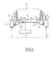
- Figure 1 shows schematically the front axle 10 of a motor vehicle which is equipped with a bar 12 anti-roll according to the state of the art.
- the anti-roll bar 12 which is substantially U-shaped consists of a central part 14 which is pivotally mounted in guide means 16, connected to the structure of the vehicle, in the transverse direction T of the vehicle.
- the central part 14 comprises at each of its ends a lever 18 which extends in a plane perpendicular to the transverse direction of the central part 14.
- the free ends 20 of the levers 18 are connected to the end of a rod 22 integral with a piston 24 which is mounted in translation in a casing 26 of a hydraulic actuator 28.
- the piston 24 defines inside the casing 26 a upper compression chamber 30 and a lower trigger 32.
- the upper free end 34 of the casing 26 is integral with the part 36 of the shock absorbers 38 which is connected mechanically at wheel 40 and which is movable relative to the vehicle structure.
- each shock absorber 38 when the part 36 of each shock absorber 38 is rigidly connected to the free end of the lever 18 corresponding, and that the vehicle tilts along an axis of longitudinal orientation, the two levers 18 pivot according to a opposite direction from each other, around the transverse direction T. The pivoting creates a torsional moment in the central part 14 of bar 12.
- the resistance of the central part 14 is opposed to this pivoting and therefore limits the angular offset of levers 18 and the tilting of the vehicle around the steering longitudinal.
- Disengaging the anti-roll bar 12 consists of allowing the movement of the parts 36 of the shock absorbers 38 without causing deformation of the central part 14 of the bar 12.
- the piston 24 includes a valve, not shown, which is movable between a first and a second positions which allow or not disengage the bar 12 roll.
- Determining the moments of disengagement of the bar 12 anti-roll can be performed by a control unit 42 from information, such as information representative of the angular position of the steering wheel, provided by sensors.
- the invention offers a declutching system 50 from the anti-roll bar 12 of a motor vehicle according to the state of the vehicle which is driven by information representative of the angular position of the steering wheel which is provided by a device 54 for power steering of the vehicle.
- power steering device is, by way of nonlimiting example, hydraulic type. Without departing from the scope of the invention, the power steering device can also similarly be electric type.
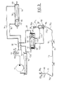
- the hydraulic type power steering device 54 mainly consists of a source 56 of liquid under pressure which supplies an actuator 58 of power-assisted steering through a valve 60, of known type, controlled by the steering wheel steering 62 of the vehicle.
- the actuator 58 consists of a body 64 in which a piston 66 delimiting first and second chambers 68, 70 respectively is mounted movable in transverse translation.
- the piston 66 carries on each of its transverse walls a assist rod 72 and 74 which extends transversely across rooms 68 and 70 respectively.
- the displacement of the piston 66 allows through the rods 72 and 74 to assist the pivoting of the wheels, that is to say reduce the effort that the driver must exert on the steering wheel direction 62 to rotate them and change the direction of the vehicle.
- Source 56 provides a constant flow of liquid assistance.
- Figure 2 shows the steering wheel 62 in a first neutral position which corresponds to the position of the wheels of the vehicle when moving in a straight line.
- the valve 60 directs the entire flow of assistance liquid towards the supply tank 75 of pump 56, i.e. the assistance liquid circulates in closed circuit between pump 56 and valve 60 and tank 75.
- FIG. 3 represents, by way of nonlimiting example, the steering wheel 62 turned, according to arrow F, in another position which corresponds to a position of the wheels when the vehicle is turning, here the steering wheel is turned to the left.
- the valve 60 then directs part of the assistance liquid flow in a first supply conduit 76 of the first chamber 68 of the actuator 58.
- the second conduit 78 makes it possible to evacuate from the second chamber 70, via valve 60, to the reservoir supply 75, the assistance liquid corresponding to the volume introduced into the first chamber 68.
- the part of the assistance liquid flow directed towards the first chamber 68 precisely depends on the position angle of the steering wheel relative to its first neutral position of in order to assist the swiveling of the wheels without affecting their pivot angles.
- the fluid pressure increases in one of the conduits 76 or 78 depending on the direction in which the steering wheel 62.
- the pressure increases in the duct 76.
- the information representative of the position angle of the steering wheel 62 which controls the declutching system 50 of the anti-roll bar 12 is the value of steering fluid assist pressure assisted.
- the declutching system 50 comprises a double acting hydraulic cylinder 80 with two chambers upper and lower 82 and 84 are powered by a second liquid.
- the hydraulic cylinder 80 is interposed between the free end 20a of a lever 18a of the anti-roll bar 12 and the part 36a of the shock absorber 38a which is mechanically connected to the wheel corresponding and which is mobile with respect to the structure of the vehicle.
- the free end 20b of the other lever 18b is here connected to the movable part 36b of the shock absorber 38b corresponding by through a rigid rod 86.
- the hydraulic cylinder 80 makes it possible to lock the relative movements of the free end 20a of the lever 18a and the movable part 36a of the corresponding shock absorber 38a when the assistance fluid pressure value is greater than one predetermined value and unlock their relative movements when the pressure value is less than or equal to the value predetermined.
- the locking cylinder 80 is controlled by a distributor 88 which comprises a drawer 90 movable between two extreme locking positions located on either side of a intermediate release position.
- the drawer 90 is returned to its unlocking position by elastic means which are here springs 92 arranged in transverse chambers 94 and 96 located on either side other side of drawer 90.
- the drawer is controlled to its locking positions by the assistance fluid and more particularly when the value of the fluid assistance pressure is greater than a value predetermined.
- transverse chambers 94 and 96 are connected to the first and second supply lines 76 and 78 via pilot lines 98 and 100 respectively.
- the distributor 88 makes it possible to form a loop hydraulic which allows the free circulation of the second fluid hydraulic between the upper 82 and lower 84 chambers of the locking cylinder 80.
- the movements of the free end 20a of the lever 18a of the anti-roll bar 12 are free relative to the movable part 36a of the corresponding shock absorber 38a.
- the anti-roll bar 12 is disengaged, which allows, in a straight line, to ensure comfort optimal driving and handling of the vehicle.
- the pressure increases in the first conduit supply 76, causing the piston 66 to move to the left as well as the movement of the drawer 90.
- the pressure value, in the supply duct 76 is greater than a predetermined value, which also corresponds to a predetermined pressure difference between the first and the second conduits 76 and 78, the drawer 90 is moved to a extreme locking position, i.e. the chamber 102 no longer allows free movement between the upper rooms and lower 82 and 84 of the jack 80.
- the predetermined value of the pressure which determines the locking and disengaging moments of the anti-roll bar 12 directly depends on the setting value of the springs 92.
- the drawer 90 is movable between an unlocking position shown in the Figure 4 and an extreme locking position shown in the figure 5.
- the drawer 90 is returned to its unlocking position by a spring 92 arranged in a transverse chamber 108 of the distributor 88.
- the drawer 90 is piloted towards its locking position by the assistance fluid and more particularly by the value of the assist fluid pressure.
- a transverse chamber 110 which is opposite the chamber 108, with respect to the drawer 90, is connected, by a conduit 114, to the conduit 112 connecting the source 56 of pressurized liquid and valve 60 piloted.
- the distributor 88 makes it possible to form the loop hydraulic which allows the free circulation of the second fluid hydraulic between upper 82 and lower 84 chambers hydraulic cylinder 80.
- the movements of the free end 20a of the lever 18a of the anti-roll bar 12 are free relative to the movable part 36a of the corresponding shock absorber 38a.
- the anti-roll bar 12 is disengaged.
- This variant embodiment makes it possible in particular to decrease the number of clutch system components 50 of the anti-roll bar 12.
Landscapes
- Engineering & Computer Science (AREA)
- Mechanical Engineering (AREA)
- Automation & Control Theory (AREA)
- Vehicle Body Suspensions (AREA)
Abstract
Description
caractérisé en ce que ladite information représentative est fournie par un dispositif de direction assistée du véhicule.
- le dispositif de direction assistée est de type électrique ;
- le dispositif de direction assistée est de type hydraulique;
- l'information représentative de la position angulaire du volant est la valeur de la pression du liquide d'assistance du dispositif de direction assistée ;
- le système de débrayage de la barre antiroulis comporte un vérin hydraulique à double effet dont les chambres sont alimentées par un second liquide et qui est interposé entre l'une des extrémités libres de la barre antiroulis et la partie d'un amortisseur mobile par rapport à la structure du véhicule, de façon à verrouiller leurs mouvements relatifs lorsque la valeur de la pression du liquide d'assistance est supérieure à une valeur prédéterminée et à déverrouiller leurs mouvements relatifs lorsque la valeur de la pression est inférieure ou égale à la valeur prédéterminée ;
- le vérin de verrouillage est commandé par un distributeur qui forme une boucle hydraulique permettant la libre circulation du second fluide hydraulique et les mouvements des extrémités libres de la barre antiroulis par rapport à la structure du véhicule lorsque la valeur de la pression du liquide d'assistance est inférieure ou égale à la valeur prédéterminée, et qui bloque la circulation du second fluide hydraulique et les mouvements de ladite extrémité libre de la barre antiroulis lorsque la valeur de la pression du liquide d'assistance est supérieure à la valeur prédéterminée ;
- le distributeur comporte un tiroir qui est mobile entre une position de déverrouillage dans laquelle le second fluide circule librement dans la boucle hydraulique et vers laquelle il est rappelé par des moyens élastiques, et au moins une position de verrouillage dans laquelle il bloque la circulation du second fluide hydraulique et vers laquelle il est piloté par le liquide d'assistance lorsque sa valeur est supérieure à la valeur prédéterminée.
- la figure 1 représente de façon schématique le train avant d'un véhicule automobile qui est équipé d'une barre antiroulis selon l'état de la technique ;
- la figure 2 représente de façon schématique, en position débrayée, les moyens de pilotage de débrayage de la barre antiroulis réalisés selon les enseignements de l'invention ;
- la figure 3 est une vue similaire à celle représentée à la figure précédente, les moyens de pilotage de débrayage de la barre antiroulis étant dans une seconde position embrayée ;
- la figure 4 représente de façon schématique, en position débrayée, les moyens de pilotage de débrayage de la barre antiroulis réalisés selon une variante de réalisation de l'invention;
- la figure 5 est une vue similaire à celle représentée à la figure précédente, les moyens de pilotage de débrayage de la barre antiroulis étant dans une seconde position embrayée ;
Claims (3)
- Système (50) de débrayage d'une barre (12) antiroulis de véhicule automobile en fonction de l'état du véhicule, du type qui est piloté par une information représentative de la position angulaire du volant de direction (62), et du type dans lequel cette information représentative est la valeur de la pression du liquide d'assistance fournie par un dispositif (54) de direction assistée hydraulique du véhicule,
caractérisé en ce qu'il comporte un vérin hydraulique (80) à double effet dont les chambres sont alimentées par un second liquide et qui est interposé entre l'une des extrémités libres (20) de la barre (12) antiroulis et la partie (36) d'un amortisseur (38) mobile par rapport à la structure du véhicule, de façon à verrouiller leurs mouvements relatifs lorsque la valeur de la pression du liquide d'assistance est supérieure à une valeur prédéterminée et à déverrouiller leurs mouvements relatifs lorsque la valeur de la pression est inférieure ou égale à la valeur prédéterminée. - Système (50) de débrayage d'une barre (12) antiroulis selon la revendication précédente, caractérisé en ce que le vérin (80) de verrouillage est commandé par un distributeur (88) qui forme une boucle hydraulique permettant la libre circulation du second fluide hydraulique et les mouvements des extrémités libres (20) de la barre (12) antiroulis par rapport à la partie mobile (36) de l'amortisseur (38) lorsque la valeur de la pression du liquide d'assistance est inférieure ou égale à la valeur prédéterminée, et qui bloque la circulation du second fluide hydraulique et les mouvements de ladite extrémité libre (20) de la barre (12) antiroulis lorsque la valeur de la pression du liquide d'assistance est supérieure à la valeur prédéterminée.
- Système (50) de débrayage d'une barre (12) antiroulis selon la revendication précédente, caractérisé en ce que le distributeur (88) comporte un tiroir (90) qui est mobile entre une position de déverrouillage dans laquelle le second fluide circule librement dans la boucle hydraulique et vers laquelle il est rappelé par des moyens élastiques (92), et au moins une position de verrouillage dans laquelle il bloque la circulation du second fluide hydraulique et vers laquelle il est piloté par le liquide d'assistance lorsque sa valeur est supérieure à la valeur prédéterminée.
Applications Claiming Priority (2)
| Application Number | Priority Date | Filing Date | Title |
|---|---|---|---|
| FR0110434 | 2001-08-03 | ||
| FR0110434A FR2828136B1 (fr) | 2001-08-03 | 2001-08-03 | Systeme de debrayage d'une barre antiroulis de vehicule automobile |
Publications (2)
| Publication Number | Publication Date |
|---|---|
| EP1281541A1 true EP1281541A1 (fr) | 2003-02-05 |
| EP1281541B1 EP1281541B1 (fr) | 2007-03-07 |
Family
ID=8866268
Family Applications (1)
| Application Number | Title | Priority Date | Filing Date |
|---|---|---|---|
| EP20020291954 Expired - Lifetime EP1281541B1 (fr) | 2001-08-03 | 2002-08-02 | Système de débrayage d'une barre antiroulis de véhicule automobile |
Country Status (3)
| Country | Link |
|---|---|
| EP (1) | EP1281541B1 (fr) |
| DE (1) | DE60218579T2 (fr) |
| FR (1) | FR2828136B1 (fr) |
Cited By (4)
| Publication number | Priority date | Publication date | Assignee | Title |
|---|---|---|---|---|
| WO2007016897A3 (fr) * | 2005-08-05 | 2007-05-03 | Zahnradfabrik Friedrichshafen | Vehicule automobile |
| CN103303094A (zh) * | 2013-06-03 | 2013-09-18 | 湖南大学 | 一种汽车横向稳定装置 |
| US20150165855A1 (en) * | 2013-12-18 | 2015-06-18 | Automotive Research & Testing Center | Active vehicle with a variable inclination apparatus and method of using the same |
| FR3101809A1 (fr) * | 2019-10-09 | 2021-04-16 | Hutchinson | Dispositif antiroulis pour véhicule automobile. |
Families Citing this family (1)
| Publication number | Priority date | Publication date | Assignee | Title |
|---|---|---|---|---|
| CN113232479B (zh) * | 2021-05-25 | 2022-04-29 | 东风汽车集团股份有限公司 | 一种半主动防侧倾系统以及汽车 |
Citations (12)
| Publication number | Priority date | Publication date | Assignee | Title |
|---|---|---|---|---|
| US2802674A (en) * | 1955-11-16 | 1957-08-13 | Gen Motors Corp | Roll control system for a motor vehicle |
| GB1012087A (en) * | 1959-10-31 | 1965-12-08 | Daimler Benz Ag | Improvements relating to body-stabilising arrangements of motor vehicles |
| FR2142065A1 (fr) * | 1971-06-16 | 1973-01-26 | Langen & Co | |
| JPS63162314A (ja) * | 1986-12-24 | 1988-07-05 | Toyota Motor Corp | 車両のロ−ル剛性制御装置 |
| JPS63275418A (ja) * | 1987-05-01 | 1988-11-14 | Toyota Motor Corp | 車輌のスタビライザ制御装置 |
| US4892329A (en) * | 1987-11-19 | 1990-01-09 | Nippondenso Co., Ltd. | Stabilizer control apparatus for use in motor vehicles |
| US5161822A (en) * | 1990-11-26 | 1992-11-10 | Tlc Suspension | Tilt correction system |
| FR2697474A1 (fr) * | 1992-11-04 | 1994-05-06 | Renault | Dispositif anti-roulis et véhicule automobile équipé d'un tel dispositif. |
| US5480186A (en) * | 1994-12-23 | 1996-01-02 | Ford Motor Company | Dynamic roll control system for a motor vehicle |
| US5549328A (en) * | 1995-01-17 | 1996-08-27 | Gabriel Ride Control Products, Inc. | Roll control system |
| US5630623A (en) * | 1994-08-15 | 1997-05-20 | Kelsey Hayes | Vehicle roll control system |
| EP1022169A2 (fr) | 1999-01-22 | 2000-07-26 | Delphi Technologies, Inc. | Système de réglage du roulis d'un véhicule automobile |
Family Cites Families (5)
| Publication number | Priority date | Publication date | Assignee | Title |
|---|---|---|---|---|
| DE1041813B (de) * | 1957-03-15 | 1958-10-23 | Daimler Benz Ag | Einrichtung zur Kurvenstabilisierung, insbesondere bei Kraftfahrzeugen |
| JPS60169314A (ja) * | 1984-02-14 | 1985-09-02 | Nissan Motor Co Ltd | 車両用スタビライザ |
| DE3740244A1 (de) * | 1987-11-27 | 1989-06-08 | Daimler Benz Ag | Stabilisator fuer kraftfahrzeuge |
| FR2761010B1 (fr) * | 1997-03-19 | 2001-12-07 | Peugeot | Dispositif anti-devers pour un vehicule automobile |
| DE19950624A1 (de) * | 1999-10-20 | 2001-04-26 | Zf Lenksysteme Gmbh | Aktuator |
-
2001
- 2001-08-03 FR FR0110434A patent/FR2828136B1/fr not_active Expired - Fee Related
-
2002
- 2002-08-02 DE DE2002618579 patent/DE60218579T2/de not_active Expired - Lifetime
- 2002-08-02 EP EP20020291954 patent/EP1281541B1/fr not_active Expired - Lifetime
Patent Citations (12)
| Publication number | Priority date | Publication date | Assignee | Title |
|---|---|---|---|---|
| US2802674A (en) * | 1955-11-16 | 1957-08-13 | Gen Motors Corp | Roll control system for a motor vehicle |
| GB1012087A (en) * | 1959-10-31 | 1965-12-08 | Daimler Benz Ag | Improvements relating to body-stabilising arrangements of motor vehicles |
| FR2142065A1 (fr) * | 1971-06-16 | 1973-01-26 | Langen & Co | |
| JPS63162314A (ja) * | 1986-12-24 | 1988-07-05 | Toyota Motor Corp | 車両のロ−ル剛性制御装置 |
| JPS63275418A (ja) * | 1987-05-01 | 1988-11-14 | Toyota Motor Corp | 車輌のスタビライザ制御装置 |
| US4892329A (en) * | 1987-11-19 | 1990-01-09 | Nippondenso Co., Ltd. | Stabilizer control apparatus for use in motor vehicles |
| US5161822A (en) * | 1990-11-26 | 1992-11-10 | Tlc Suspension | Tilt correction system |
| FR2697474A1 (fr) * | 1992-11-04 | 1994-05-06 | Renault | Dispositif anti-roulis et véhicule automobile équipé d'un tel dispositif. |
| US5630623A (en) * | 1994-08-15 | 1997-05-20 | Kelsey Hayes | Vehicle roll control system |
| US5480186A (en) * | 1994-12-23 | 1996-01-02 | Ford Motor Company | Dynamic roll control system for a motor vehicle |
| US5549328A (en) * | 1995-01-17 | 1996-08-27 | Gabriel Ride Control Products, Inc. | Roll control system |
| EP1022169A2 (fr) | 1999-01-22 | 2000-07-26 | Delphi Technologies, Inc. | Système de réglage du roulis d'un véhicule automobile |
Non-Patent Citations (2)
| Title |
|---|
| PATENT ABSTRACTS OF JAPAN vol. 012, no. 428 (M - 762) 11 November 1988 (1988-11-11) * |
| PATENT ABSTRACTS OF JAPAN vol. 013, no. 076 (M - 800) 21 February 1989 (1989-02-21) * |
Cited By (5)
| Publication number | Priority date | Publication date | Assignee | Title |
|---|---|---|---|---|
| WO2007016897A3 (fr) * | 2005-08-05 | 2007-05-03 | Zahnradfabrik Friedrichshafen | Vehicule automobile |
| CN103303094A (zh) * | 2013-06-03 | 2013-09-18 | 湖南大学 | 一种汽车横向稳定装置 |
| US20150165855A1 (en) * | 2013-12-18 | 2015-06-18 | Automotive Research & Testing Center | Active vehicle with a variable inclination apparatus and method of using the same |
| US9061564B1 (en) * | 2013-12-18 | 2015-06-23 | Automotive Research & Testing Center | Active vehicle with a variable inclination apparatus and method of using the same |
| FR3101809A1 (fr) * | 2019-10-09 | 2021-04-16 | Hutchinson | Dispositif antiroulis pour véhicule automobile. |
Also Published As
| Publication number | Publication date |
|---|---|
| DE60218579D1 (de) | 2007-04-19 |
| FR2828136B1 (fr) | 2005-11-11 |
| EP1281541B1 (fr) | 2007-03-07 |
| DE60218579T2 (de) | 2007-11-29 |
| FR2828136A1 (fr) | 2003-02-07 |
Similar Documents
| Publication | Publication Date | Title |
|---|---|---|
| KR100396040B1 (ko) | 적어도3개의바퀴가장착된자체안정식의방향제어가능한차량 | |
| EP2585320B1 (fr) | Dispositif de contrôle de l'inclinaison d'un cadre monté sur un train de roulement inclinable | |
| US7931286B2 (en) | Vehicle lean and alignment control system | |
| RU2205122C2 (ru) | Средство передвижения с изменяемым углом наклона | |
| EP1578626A1 (fr) | Dispositif de support de roue a triple charniere, dispositif de suspension et vehicule comprenant ledit dispositif de support | |
| EP1931527B1 (fr) | Dispositif de suspension pour véhicule | |
| EP3691959A1 (fr) | Véhicule automobile routier attelable à suspension et direction compacte | |
| FR3101809A1 (fr) | Dispositif antiroulis pour véhicule automobile. | |
| FR2927020A1 (fr) | Systeme anti-roulis pour vehicule automobile. | |
| FR2833233A1 (fr) | Dispositif de suspension d'une roue | |
| FR2636031A1 (fr) | Direction toutes-roues pour vehicules automobiles | |
| EP2019023A1 (fr) | Train arrière directeur pour automobile, comportant un pivot de roue déformable | |
| EP1281541B1 (fr) | Système de débrayage d'une barre antiroulis de véhicule automobile | |
| FR2927848A3 (fr) | Dispositif anti-roulis en opposition | |
| EP1799472B1 (fr) | Systeme de commande de l'inclinaison et de l'alignement d'un vehicule | |
| CN114174162A (zh) | 具有作用在减震器上的倾斜阻挡系统的滚动机动车辆 | |
| EP3642059B1 (fr) | Véhicule automobile routier attelable | |
| FR2926492A1 (fr) | Sous ensemble de train roulant de vehicule | |
| EP3215377B1 (fr) | Porte-fusée pour un essieu de véhicule automobile | |
| FR2692220A1 (fr) | Véhicule routier à disposition de roues perfectionnée. | |
| EP1015266B1 (fr) | Systeme de suspension pour vehicule roulant a essieux interactifs | |
| FR2999143A1 (fr) | Vehicule equipe d'un train directeur a geometrie amelioree | |
| FR2937286A1 (fr) | Train arriere de vehicule automobile a roues directrices | |
| FR2927021A1 (fr) | Systeme anti-roulis pour vehicule automobile. | |
| FR3088255A1 (fr) | Barre stabilisatrice scindee en au moins deux troncons accouples par un dispositif d'accouplement |
Legal Events
| Date | Code | Title | Description |
|---|---|---|---|
| PUAI | Public reference made under article 153(3) epc to a published international application that has entered the european phase |
Free format text: ORIGINAL CODE: 0009012 |
|
| AK | Designated contracting states |
Designated state(s): AT BE BG CH CY CZ DE DK EE ES FI FR GB GR IE IT LI LU MC NL PT SE SK TR |
|
| AX | Request for extension of the european patent |
Extension state: AL LT LV MK RO SI |
|
| AKX | Designation fees paid | ||
| REG | Reference to a national code |
Ref country code: DE Ref legal event code: 8566 |
|
| 17P | Request for examination filed |
Effective date: 20031007 |
|
| RBV | Designated contracting states (corrected) |
Designated state(s): BE DE ES GB |
|
| 17Q | First examination report despatched |
Effective date: 20050310 |
|
| GRAP | Despatch of communication of intention to grant a patent |
Free format text: ORIGINAL CODE: EPIDOSNIGR1 |
|
| GRAS | Grant fee paid |
Free format text: ORIGINAL CODE: EPIDOSNIGR3 |
|
| GRAA | (expected) grant |
Free format text: ORIGINAL CODE: 0009210 |
|
| AK | Designated contracting states |
Kind code of ref document: B1 Designated state(s): BE DE ES GB |
|
| REG | Reference to a national code |
Ref country code: GB Ref legal event code: FG4D Free format text: NOT ENGLISH |
|
| REF | Corresponds to: |
Ref document number: 60218579 Country of ref document: DE Date of ref document: 20070419 Kind code of ref document: P |
|
| PG25 | Lapsed in a contracting state [announced via postgrant information from national office to epo] |
Ref country code: ES Free format text: LAPSE BECAUSE OF FAILURE TO SUBMIT A TRANSLATION OF THE DESCRIPTION OR TO PAY THE FEE WITHIN THE PRESCRIBED TIME-LIMIT Effective date: 20070618 |
|
| GBT | Gb: translation of ep patent filed (gb section 77(6)(a)/1977) |
Effective date: 20070530 |
|
| PLBE | No opposition filed within time limit |
Free format text: ORIGINAL CODE: 0009261 |
|
| STAA | Information on the status of an ep patent application or granted ep patent |
Free format text: STATUS: NO OPPOSITION FILED WITHIN TIME LIMIT |
|
| 26N | No opposition filed |
Effective date: 20071210 |
|
| BERE | Be: lapsed |
Owner name: RENAULT S.A.S. Effective date: 20070831 |
|
| PG25 | Lapsed in a contracting state [announced via postgrant information from national office to epo] |
Ref country code: BE Free format text: LAPSE BECAUSE OF NON-PAYMENT OF DUE FEES Effective date: 20070831 |
|
| PGFP | Annual fee paid to national office [announced via postgrant information from national office to epo] |
Ref country code: GB Payment date: 20160819 Year of fee payment: 15 Ref country code: DE Payment date: 20160822 Year of fee payment: 15 |
|
| REG | Reference to a national code |
Ref country code: DE Ref legal event code: R119 Ref document number: 60218579 Country of ref document: DE |
|
| GBPC | Gb: european patent ceased through non-payment of renewal fee |
Effective date: 20170802 |
|
| PG25 | Lapsed in a contracting state [announced via postgrant information from national office to epo] |
Ref country code: GB Free format text: LAPSE BECAUSE OF NON-PAYMENT OF DUE FEES Effective date: 20170802 Ref country code: DE Free format text: LAPSE BECAUSE OF NON-PAYMENT OF DUE FEES Effective date: 20180301 |