EP1281539B1 - Writing implement - Google Patents
Writing implement Download PDFInfo
- Publication number
- EP1281539B1 EP1281539B1 EP01917511A EP01917511A EP1281539B1 EP 1281539 B1 EP1281539 B1 EP 1281539B1 EP 01917511 A EP01917511 A EP 01917511A EP 01917511 A EP01917511 A EP 01917511A EP 1281539 B1 EP1281539 B1 EP 1281539B1
- Authority
- EP
- European Patent Office
- Prior art keywords
- ink
- chamber
- writing instrument
- writing
- walls
- Prior art date
- Legal status (The legal status is an assumption and is not a legal conclusion. Google has not performed a legal analysis and makes no representation as to the accuracy of the status listed.)
- Expired - Lifetime
Links
Images







Classifications
-
- B—PERFORMING OPERATIONS; TRANSPORTING
- B43—WRITING OR DRAWING IMPLEMENTS; BUREAU ACCESSORIES
- B43K—IMPLEMENTS FOR WRITING OR DRAWING
- B43K5/00—Pens with ink reservoirs in holders, e.g. fountain-pens
- B43K5/02—Ink reservoirs
- B43K5/06—Ink reservoirs with movable pistons for withdrawing ink from an ink-receptacle
- B43K5/08—Ink reservoirs with movable pistons for withdrawing ink from an ink-receptacle with ink-supplying valves
-
- B—PERFORMING OPERATIONS; TRANSPORTING
- B43—WRITING OR DRAWING IMPLEMENTS; BUREAU ACCESSORIES
- B43K—IMPLEMENTS FOR WRITING OR DRAWING
- B43K7/00—Ball-point pens
- B43K7/02—Ink reservoirs; Ink cartridges
-
- B—PERFORMING OPERATIONS; TRANSPORTING
- B43—WRITING OR DRAWING IMPLEMENTS; BUREAU ACCESSORIES
- B43K—IMPLEMENTS FOR WRITING OR DRAWING
- B43K5/00—Pens with ink reservoirs in holders, e.g. fountain-pens
- B43K5/02—Ink reservoirs
-
- B—PERFORMING OPERATIONS; TRANSPORTING
- B43—WRITING OR DRAWING IMPLEMENTS; BUREAU ACCESSORIES
- B43K—IMPLEMENTS FOR WRITING OR DRAWING
- B43K8/00—Pens with writing-points other than nibs or balls
- B43K8/02—Pens with writing-points other than nibs or balls with writing-points comprising fibres, felt, or similar porous or capillary material
- B43K8/03—Ink reservoirs; Ink cartridges
Definitions
- the present invention relates to a writing instrument provided with an ink supply mechanism with a simple structure, and to a writing instrument enabling an ink storing amount to be increased, and further enabling ink to be supplied stably to a writing element.
- a writing instrument with a slide plug provided in an ink chamber as disclosed in Japan Laid-Open Patent Publication HEI7-20753 .
- the slide plug is formed to be slidable in the axis direction with the ink densely filled in the ink chamber, partitions the ink chamber into a portion of the ink and a portion of the air, slides corresponding to consumption, expansion and contraction of the ink, and thereby always maintains a pressure of the ink in the ink chamber at an atmospheric pressure.
- Such a plug type of writing instrument is excellent in ink pressure compensation function, but has inconveniences such that precision control in production and assembly is strict to enable the slide plug to smoothly slide with no resistance and thereby the cost is increased.
- JP Patent 2534821 there is a gas-liquid exchange/feeder type of writing instrument as disclosed in JP Patent 2534821 .
- This type of writing instrument is configured so that a small amount of air is led into the ink chamber in return for the ink consumption, and thereby the ink pressure inside the ink chamber is always maintained to be equal to the atmospheric pressure.
- a feeder reverseverser chamber
- the gas-liquid exchange/feeder type of writing instrument generally has a structure in which a feeder communicating with the atmosphere side communicates with an ink chamber using a passage with a thin diameter.
- the ink In the passage with a thin diameter, the ink is usually held by capillary force and is sealed. Then, when a pressure difference occurs between the ink chamber and the outside, the air is led into the ink chamber through the passage with a thin diameter, or the ink is pushed out of the ink chamber, and the pushed-out ink is stored in the feeder.
- Such a type of writing instrument does not require a variable portion inherently and has a simple structure, but makes it difficult to lead the air into an ink chamber corresponding to ink consumption (gas-liquid exchange) and to hold and control the ink pushed out of the ink chamber, and thus has disadvantages that it is difficult to assure stable operations.
- EP 0 234 493 discloses an ink writing instrument in which the ink storage space is divided into individual chambers that are inside the housing and are arranged axially behind each other.
- the chambers are connected with the writing element by an ink guide.
- Capillary ring gaps exist between the ink chamber separating walls and the peripheral surface of the ink guide.
- the ink-filled chambers are emptied one after the other by capillaries provided in the outer periphery of the ink guide, and air enters the chambers by a ventilation duct in the mouthpiece of the instrument and capillary ventilation openings provided at the outer periphery of the separating walls.
- EP 0 624 483 discloses a writing instrument having a feeder chamber communicating with the atmosphere and an ink reservoir, separated by a partition member.
- a first capillary flow passage is provided between the outer periphery of the partition member and the inner periphery of the body of the writing instrument, and a second annular capillary passage is formed between the outer periphery of the front portion of an ink supplying passage and the partition member.
- DE 195 29 865 discloses a liquid applicator including a container for freely moveable liquid, a capillary storage means for temporarily receiving liquid upon a change in air pressure and/or temperature of the environment, an applicator element and a capillary air inlet for compensation in respect of liquids taken from the container.
- the applicator element is formed integrally with an ink supply wick extending through the storage means of capillary material.
- a writing instrument according to the present invention is defined in the claims.
- the communication hole formed in each wall is usually sealed with an ink membrane held by capillary force, and the ink in the ink chamber is supplied to the writing element through the ink supply member.
- the ink chamber is sealed in the vertical direction. As a result, the hydraulic pressure corresponding to length of the ink chamber is canceled, and therefore, does not affect the writing element.
- the seal due to the ink membrane of the communication hole formed in the wall between the reservoir chamber and ink chamber is broken, and a small amount of air is led from the reservoir chamber into the ink chamber, thereby preventing an occurrence of a negative pressure inside the ink chamber.
- the seal due to the ink membrane of the communication hole formed in the wall between the reservoir chamber and ink chamber is broken, and the ink is pushed out of the ink chamber to the reservoir chamber, thereby canceling the expansion in pressure inside the ink chamber.
- a configuration is preferable in which the ink pushed into the reservoir chamber is fed to the writing element to be consumed or returned to the ink chamber when the pressure inside the ink chamber becomes a negative pressure.
- the ink chamber is partitioned into a plurality of small chambers in the axis direction by at least one wall.
- the ink is consumed, the ink is consumed in a first small chamber nearest the reservoir chamber where the gas and liquid are exchanged, and the air is led to only the first small chamber from the reservoir chamber. Accordingly, even when the ink in the first small chamber is almost replaced with the air, since the capacity of the first small chamber is small, a small amount of air expands due to changes in temperature, and therefore an amount of ink pushed into the reservoir is small.
- the gas and liquid are exchanged between the first and second small chambers, and the air is led into the second small chamber.
- the ink pushed out of the second small chamber is held in the first small chamber.
- the first small chamber serves as a reservoir chamber, and thereafter, another small chamber becoming empty servers as a reservoir chamber sequentially.
- this writing instrument has such a simple structure that the inside of the main body of the writing instrument is partitioned using a plurality of walls, thereby forming small chambers serving as a reservoir chamber and ink chamber, a communication hole of ink is formed in each wall, and that an ink supply member penetrates and is inserted through the walls, does not have any variable portion, thereby having simple operations, and therefore is high in reliability and easy in production.
- FIGs.1 and 2 illustrate a writing instrument provided with a ball chip using water-soluble ink.
- reference numeral "1" denotes a barrel of the writing instrument, i.e., a main body of the writing instrument.
- a wall 14 is provided inside the main body 1 in the direction perpendicular to the axis direction.
- a portion at a tail end side partitioned by the wall 14 is configured to be a cylinder-shaped ink chamber 2 with ink A filled therein and a reservoir chamber 10 with a front end side in the form of a cylinder.
- the wall 14 is configured by pressing a disk-shaped member inside the main body 1, and is provided with a through hole 15 at its center portion.
- the main body 1 is provided with an end plug 3 at its tail end portion, and is further provided with a chip ball holder 4 at its front end portion.
- the front end portion of the chip holder 4 is provided with a ball chip 5 for water-soluble ink.
- a rubber boot 6 for anti-skid is provided on the outer periphery of the front end portion of the main body 1.
- An upper end portion of the chip holder 4 is formed in the shape of a cup, inserted into the main body 1, and forms an ink receiving portion 11 of the reservoir chamber 10.
- a bottom of the receiving portion 11 is provided with a porous ink holding member 13 made of a fiber material, and thus formed to impregnate ink therewith to hold.
- the ink holding member 13 does not need to be provided in particular, and is not limited in structure to a porous member composed of a fiber material even if the member 13 is provided.
- the atmosphere communication passage 12 is configured to prevent the ink in the reservoir chamber 10 from leaking outside. In this case, by providing the porous ink holding member 13 inside the reservoir chamber 10, the ink having flowed in the reservoir chamber is impregnated and held in the ink holding member, and assuredly prevented from leaking from the atmosphere communication passage 12 to the outside.
- the ink supply member 16 is a member referred to a relay core, composed of a porous rod-shaped member made of a large number of fibers gathered and compressed parallel to the axis direction, and supplies the ink by capillary force.
- members referred to a relay core include one obtained by applying water-non-permeable coating to the outer periphery of a fiber-gathered member as described above.
- the member without water-non-permeable coating on its outer periphery is used, and thus is capable of absorbing the ink from the outer periphery.
- the ink is capable of flowing in and out through the periphery of the ink supply member 16 over its entire length.
- the ink is reliably and stably supplied from the ink chamber 2 to writing element 5 by capillary force, and since the porous relay core itself has the ink flow rate adjusting function, it is possible to supply the ink stably.
- the ink supply member 16 is provided substantially over the entire length along the center axis line of the main body 1, and the front end portion of the member 16 is held in a holding hole 18 formed in the chip holder 4 with a gap of some extent. A tail end portion of the ink supply member 16 is engaged and held in a holding member 17 formed in the tail end portion of the main body 1.
- a middle portion of the ink supply member 16 penetrates the ink chamber 2, through hole 15 of the wall 14 and reservoir chamber 10.
- an inner diameter of the through hole 15 of the wall 14 is formed to be a little larger than an outer diameter of the ink supply member 16, and a predetermined circular gap G is prescribed between the outer periphery of the ink supply member 16 and the inner periphery of the through hole 15.
- the gap G forms a communication hole capable of holding the ink due to capillary force.
- the size of the gap G is set as appropriate corresponding to, for example, type of ink to be used, and is usually set closed to prevent the air from entering.
- the gap G of the wall 14 is sealed with an ink membrane. Accordingly, even when the writing instrument is in a substantially vertical posture with the writing element directed downward, the ink does not flow from the gap G.
- the ink A in the ink chamber 2 is supplied to the ball chip 5 through the ink supply member 16, thereby enabling writing. Then, when the ink in the ink chamber 2 is consumed by writing, the pressure inside the ink chamber 2 becomes a negative pressure. By this negative pressure, the seal of the ink membrane held in the gap G is broken, a small amount of air conforming to the consumed amount is led to the ink chamber 2 from the reservoir chamber 10 through the gap G, then the negative pressure inside the ink chamber 2 is canceled, and the pressure is made equal to the atmospheric pressure. In response to this behavior, the gap G is sealed again with the ink membrane due to capillary force.
- the air After the air is led into the ink chamber 2, the air expands or contracts due to changes in temperature. In this case, when the led air contracts, the ink membrane held in the gap G is broken and the air is introduced similarly, thereby preventing the ink chamber 2 from having a negative pressure.
- the ink membrane When the air in the ink chamber 2 expands, due to the pressure, the ink membrane is broken and the ink is pushed out of the gap G to the reservoir chamber 10.
- the pushed-out ink is impregnated in the ink holding member 13, and the ink held in the ink holding member 13 is consumed by writing, or is returned to a side of the ink chamber 2 through the ink supply member 16 when the pressure inside the ink chamber 2 becomes negative. Accordingly, an excess amount of ink does not stay in the reservoir chamber 10.
- the writing instrument as described above has a simple structure without a variable portion, and therefore is easy in production, simple in operation principle, and high in reliability.
- the gap G between the through hole 15 formed in the wall and ink supply member 16 is only a portion for controlling introduction of air and exclusion of ink into/from the ink chamber 2 for compensating for expansion and contraction due to ink consumption, changes in temperature, changes in barometric pressure in the ink chamber 2.
- the ink is always supplied to the gap G from the ink chamber 2 and ink supply member 16 to maintain the ink membrane. Accordingly, even when leaving the writing instrument unused for a long time, it does not happen that the ink in the gap G dries and thereby clogging occurs, and it is possible to secure remarkably stable operations.
- the ink chamber 2 is closed at its tail end side, and the gap G at the front end side of the chamber 2 is usually sealed with the ink membrane. Accordingly, even when letting the writing instrument stand in a posture as illustrated in FIG.1 in writing, the hydraulic pressure inside the ink chamber 2 has little effect on the ink supply member 16. Thus, the control is performed for ink stable supply.
- the porous ink supply member 16 composed of the fiber-gathered member penetrates the reservoir chamber 10 communicating with the atmosphere with the outer periphery of the member 16 exposed, thus providing the function of compensating for changes in the hydraulic pressure in this portion or in other pressure.
- the ink chamber 2 is composed of a single space, an amount of air staying in the ink chamber 2 is increased as the ink is consumed. Therefore, when an expansion amount of air is increased due to changes in temperature, an amount of ink pushed out to the reservoir chamber 10 is increased.
- FIGs.3 , 4A to 4D , 5A and 5B illustrate the first embodiment of the present invention.
- the ink chamber 2 is provided with a plurality of, for example, three walls 14a, and is partitioned in the axis direction into a first small chamber 2a, second small chamber 2b, third small chamber 2c and fourth small chamber 2d.
- These walls 14a have the same structure as that of the wall 14 which partitions the ink chamber 2 and the reservoir chamber 10.
- the ink supply member 16 penetrates the through hole 15 of each wall 14a.
- the ink chamber 2 is composed of small chambers 2a to 2d partitioned in the axis direction.
- the ink in the first small chamber 2a when the air in the first small chamber 2a expands, according to the operational principle as described above, the ink in the first small chamber 2a is pushed to the reservoir chamber 10 and stays in the reservoir chamber 10. Then, as shown in FIG.5A , when the ink in the first small chamber 2a is consumed and the chamber 2a is emptied, the air stays in the second small chamber 2b.
- the air in the chamber 2b expands, as shown in FIG.5B , the ink in the second small chamber 2b is pushed to the first small chamber 2a and stays in the chamber 2a.
- the first small chamber 2a functions as a reservoir chamber
- the second small chamber 2b and third small chamber 2c function as a reservoir chamber sequentially.
- the ink chamber 2 is divided into small chambers which function as a reservoir chamber sequentially in ascending order of height of a chamber position as the ink is consumed, whereby the need of increasing the capacity of the reservoir chamber 10 is eliminated.
- the capacity of the first small chamber 2a is small, an amount of ink pushed out of the chamber 2a is also small, and therefore, the capacity of the reservoir chamber 10 is made small.
- the capacity of the reservoir chamber 10 is made small.
- FIG.6 is a view illustrating the second embodiment of the present invention.
- a felt chip 5a is provided as a writing element.
- the present invention is not limited in writing element communicating with the ink supply member, and it is possible to attach various types of writing elements.
- FIG.7 is a view illustrating the third embodiment of the present invention.
- the front end portion of the porous ink supply member 16 extends, and forms a felt chip portion 5b.
- a writing element can be formed integrally from the material of the ink supply member 16, and such a construction simplifies the structure.
- FIG.8 is a view illustrating the fourth embodiment of the present invention.
- the ink chamber 2 is partitioned into three chambers with two walls, and the ink holding member 13 is not provided.
- the writing element is composed of a felt chip 5c with a thick diameter suitable for writing instruments providing thick handwriting such as a white board marker pen.
- the atmosphere communication passage 12 communicating with the reservoir chamber 10 is formed in a side wall of the main body of the writing instrument, thereby preventing the ink pushed to the reservoir chamber 10 from leaking outside.
- the capacity of the ink chamber 2 is increased.
- capacities of the first small chamber 2a and second small chamber 2b are small, and the capacity of the third chamber 2c is large.
- an amount of ink pushed out of the first chamber 2a is deceased so as to decrease the capacity of the ink reservoir chamber 10.
- one or more chambers at the writing element side are small, and the others are made larger as the chamber is spaced a more distance away from the writing element. It is thereby possible to effectively increase the capacity of the ink chamber 2.
- FIG.9 is a view illustrating the fifth embodiment of the present invention.
- a cup-shaped ink holding member 13a is provided in the reservoir chamber 10 to be in intimate contact with the wall 14.
- An upper portion of the cup-shaped ink holding member 13a is provided with a communication hole 30, thereby causing the reservoir chamber 10 to communicate with the inside of the ink holding member 13a.
- the ink pushed out of the first small chamber 2a stays in the cup-shaped ink holding member 13a, the ink is assuredly prevented from leaking outside. Therefore, despite the atmosphere communication passage 12 communicating with the reservoir chamber 10 being formed in a side portion of the writing element 5c in the vertical direction, the ink does not leak from the passage 12.
- FIG.10 is a view illustrating the sixth embodiment of the present invention.
- a cup-shaped ink holding member 13b is provided in the reservoir chamber 10 to be spaced a predetermined distance away from the wall 14.
- a communication groove 32 is formed on the outer periphery of an upper end portion 31 of the cup-shaped ink holding member 13b, thereby causing the reservoir chamber 10 to communicate with the inside of the ink holding member 13b.
- FIG.11 is a view illustrating the seventh embodiment of the present invention.
- a cup-shaped ink holding member 13c that maintains the sealing and is slidable in the axis direction.
- the ink pushed out of the first small chamber 2a stays in the cup-shaped ink holding member 13c, the ink is assuredly prevented from leaking outside. Further, when the air and/or ink expands/contracts in the ink chamber 2 due to changes in temperature, the slidable ink holding member 13c slides to compensate for the expansion/contraction.
- FIGs. 12A and 12B are views illustrating the eighth embodiment of the present invention.
- the front end portion of the porous ink supply member 16 extends, and forms the felt chip portion 5b.
- the inner diameter of a holding hole 18a of the chip holder 4 is greater than the outer diameter of the ink supply member 16 (felt chip portion 5b), gaps H are formed between the hole 18a and member 16, and the reservoir chamber 10 communicates with the atmosphere through the gaps H. Therefore, in this embodiment the atmosphere communication passage 12 as described previously is eliminated.
- FIG.12B on the inner periphery of a front end portion of the holding hole 18a are provided a plurality of holding projecting portions 35 that project from the periphery and hold the felt chip portion 5a.
- the gaps H usually hold the ink by capillary force and seal the reservoir chamber 10.
- the seal by the ink membrane is broken, and the chamber 10 communicates with the atmosphere. Accordingly, in the structure in this embodiment, since the gaps H are usually sealed, the ink is effectively prevented from drying.
- the face of each of walls 14 and 14a at the tail plug side is tapered and tilted towards the through hole 15.
- the ink is injected while holding the main body of the writing instrument substantially vertically with the front end side directed upward.
- the face of the wall 14 at the tail plug side is tapered, the air is guided to the tapered face and assuredly exhausted, and any air bubble does not remain at lower portions of walls 14 and 14a.
- FIG.14 illustrates the ninth embodiment of the present invention, and is a view illustrating enlarged portions of the ink chamber and reservoir chamber.
- an ink supply member 40 is composed of a rod-shaped relay core 41 made of a porous material such as a fiber-gathered member and an ink-non-permeable coating 42 that is coated on the periphery surface of the core 41.
- Part of the coating 42 is removed at portions opposed to the inner periphery of the through hole 15 and in the vicinity of the hole 15 in each of walls 14 and 14a, and such portions form communication portions 43 through which the ink flows.
- the ink is capable of flowing from the ink chamber to the inside of the ink supply member through communication portions 43, and the ink at small chambers is consumed in ascending order of height of a chamber position. Further, at portions in through holes 15 are provided communication portions 43 where the rod-shaped relay core 41 made of the porous material is exposed. Therefore, similarly to the above structures, the ink membrane is usually held in constant state in the gap G, thereby stabilizing characteristics, while it does not happen that the ink in the gap G dries and thereby clogging occurs, and it is thus possible to obtain high stability and reliability.
- the relay core 41 is coated with the coating 42 except communication portions 43 in the gap G, it is possible to prevent a solvent of the ink from evaporating from the surface of the ink supply member 40, for example, in the feeder chamber 10. Accordingly, there are advantages in the case of using fast-drying ink.
- FIG.15 illustrates the tenth embodiment of the present invention, and is a view illustrating enlarged portions of the ink chamber and reservoir chamber.
- An ink supply member 50 of this embodiment is composed of a tube with a small diameter, and communication portions 51 through which the ink flows are formed at portions opposed to inner peripheries of through holes 15 of walls 14 and 14a, respectively.
- FIG.16 illustrates the eleventh embodiment of the present invention, and is a view illustrating enlarged portions of the ink chamber and reservoir chamber.
- the ink supply member 50 is composed of a tube with a small diameter, and communication portions 51a are formed in the vicinities of through holes 15 of walls 14 and 14a.
- each of communication portions 43, 51 and 51a is only required to be formed in a position that assures the ink flow between the ink supply member and gap G in the though hole through the communication portion due to capillary force.
- each of communication holes formed on walls 14 and 14a is formed of the gap G between the ink supply member 16 and the inner periphery of the through hole 15 through which the member 16 passes.
- FIG. 18 is a view illustrating an embodiment in which the reservoir chamber 10 accommodates a bellows-shaped feeder mechanism 70.
- the feeder mechanism 70 has the same structure as that is used conventionally, where a plurality of disk-shaped members projects in the form of bellows from the center axis portion, and circular gaps between the members holds the ink due to capillary force.
- the reservoirs chamber is provided with the bellows-shaped feeder mechanism 70, the pushed-out ink is held and returned reliably.
- the ink having flowed in the reservoir chamber 10 is held in the feeder mechanism, the ink is assuredly prevented from leaking outside from a passage causing the reservoir chamber to communicate with the atmosphere.
- Fig. 18 does not correspond to the invention so far as excentric holes 62 are shown.
- the present invention is applicable to small-sized writing instruments such as a refill-type of writing instrument and writing instrument accompanying a pocketbook, and further is applicable to disposable writing instruments and other general writing instruments.
Landscapes
- Engineering & Computer Science (AREA)
- Mechanical Engineering (AREA)
- Pens And Brushes (AREA)
Description
- The present invention relates to a writing instrument provided with an ink supply mechanism with a simple structure, and to a writing instrument enabling an ink storing amount to be increased, and further enabling ink to be supplied stably to a writing element.
- Conventionally, various writing instruments have been developed of so-called direct-ink type for directly storing liquid ink in an ink chamber. Such a type of writing instrument has an advantage of capable of storing a large amount of ink, but has disadvantages of requiring mechanisms with complicated structures for adjusting an ink pressure and controlling ink supply to stably supply the ink from an ink chamber to a writing element such as a ball chip and felt chip.
- As described above, in order to stably supply the ink, it should be considered to compensate for expansion and contraction of the air in an ink chamber due to changes in temperature and barometric pressure and to compensate a hydraulic pressure of the ink from the ink chamber to the writing element in writing.
- In order to overcome the above problems, there is known a writing instrument with a slide plug provided in an ink chamber as disclosed in Japan Laid-Open Patent Publication
HEI7-20753 - Such a plug type of writing instrument is excellent in ink pressure compensation function, but has inconveniences such that precision control in production and assembly is strict to enable the slide plug to smoothly slide with no resistance and thereby the cost is increased.
- Further, as another type, there is a gas-liquid exchange/feeder type of writing instrument as disclosed in
JP Patent 2534821 - In such a type of writing instrument, when the capacity of the ink chamber is increased to increase the ink storing amount, it is required to increase the capacity of a feeder corresponding to the increased chamber capacity. However, the size of writing instrument is limited to some extent, and in such a limited space, there is a limitation in increasing the capacity of an ink chamber.
- Further, the gas-liquid exchange/feeder type of writing instrument generally has a structure in which a feeder communicating with the atmosphere side communicates with an ink chamber using a passage with a thin diameter. In the passage with a thin diameter, the ink is usually held by capillary force and is sealed. Then, when a pressure difference occurs between the ink chamber and the outside, the air is led into the ink chamber through the passage with a thin diameter, or the ink is pushed out of the ink chamber, and the pushed-out ink is stored in the feeder.
- Such a type of writing instrument does not require a variable portion inherently and has a simple structure, but makes it difficult to lead the air into an ink chamber corresponding to ink consumption (gas-liquid exchange) and to hold and control the ink pushed out of the ink chamber, and thus has disadvantages that it is difficult to assure stable operations.
-
EP 0 234 493 discloses an ink writing instrument in which the ink storage space is divided into individual chambers that are inside the housing and are arranged axially behind each other. The chambers are connected with the writing element by an ink guide. Capillary ring gaps exist between the ink chamber separating walls and the peripheral surface of the ink guide. The ink-filled chambers are emptied one after the other by capillaries provided in the outer periphery of the ink guide, and air enters the chambers by a ventilation duct in the mouthpiece of the instrument and capillary ventilation openings provided at the outer periphery of the separating walls. -
EP 0 624 483 discloses a writing instrument having a feeder chamber communicating with the atmosphere and an ink reservoir, separated by a partition member. A first capillary flow passage is provided between the outer periphery of the partition member and the inner periphery of the body of the writing instrument, and a second annular capillary passage is formed between the outer periphery of the front portion of an ink supplying passage and the partition member. -
DE 195 29 865 discloses a liquid applicator including a container for freely moveable liquid, a capillary storage means for temporarily receiving liquid upon a change in air pressure and/or temperature of the environment, an applicator element and a capillary air inlet for compensation in respect of liquids taken from the container. The applicator element is formed integrally with an ink supply wick extending through the storage means of capillary material. - It is difficult to always seal a passage with a thin diameter under a constant condition with the ink, and as a result, there are problems that characteristics are not stabilized, and the ink dries in the thin diameter, which is clogged. Thus, it is not possible to always obtain adequate stability and reliability.
- Accordingly, it is an object of the present invention to provide a gas-liquid exchange/feeder type of writing instrument enabling an increased capacity of an ink chamber.
- Further, it is a second object of the present invention to provide a gas-liquid exchange/feeder type of writing instrument with reliability in control of gas-liquid exchange and of pushed-out ink, with a simplified reliable structure, and with ease in production.
- A writing instrument according to the present invention is defined in the claims.
- The communication hole formed in each wall is usually sealed with an ink membrane held by capillary force, and the ink in the ink chamber is supplied to the writing element through the ink supply member. When letting the writing instrument stand for use in writing, since the communication hole at a lower side of the ink chamber is sealed with the ink membrane, the ink chamber is sealed in the vertical direction. As a result, the hydraulic pressure corresponding to length of the ink chamber is canceled, and therefore, does not affect the writing element.
- Further, when the ink is consumed, or the ink and/or air in the ink chamber contracts due to changes in temperature, the seal due to the ink membrane of the communication hole formed in the wall between the reservoir chamber and ink chamber is broken, and a small amount of air is led from the reservoir chamber into the ink chamber, thereby preventing an occurrence of a negative pressure inside the ink chamber. When the ink and/or air in the ink chamber expands due to changes in temperature, the seal due to the ink membrane of the communication hole formed in the wall between the reservoir chamber and ink chamber is broken, and the ink is pushed out of the ink chamber to the reservoir chamber, thereby canceling the expansion in pressure inside the ink chamber. In addition, a configuration is preferable in which the ink pushed into the reservoir chamber is fed to the writing element to be consumed or returned to the ink chamber when the pressure inside the ink chamber becomes a negative pressure.
- The ink chamber is partitioned into a plurality of small chambers in the axis direction by at least one wall. When the ink is consumed, the ink is consumed in a first small chamber nearest the reservoir chamber where the gas and liquid are exchanged, and the air is led to only the first small chamber from the reservoir chamber. Accordingly, even when the ink in the first small chamber is almost replaced with the air, since the capacity of the first small chamber is small, a small amount of air expands due to changes in temperature, and therefore an amount of ink pushed into the reservoir is small.
- Further, after the first small chamber becomes empty, the gas and liquid are exchanged between the first and second small chambers, and the air is led into the second small chamber. In this case, the ink pushed out of the second small chamber is held in the first small chamber. In other words, after the first small chamber becomes empty, the first small chamber serves as a reservoir chamber, and thereafter, another small chamber becoming empty servers as a reservoir chamber sequentially.
- By such a consecutive operation, it is possible to decrease the capacity of the reservoir chamber communicating with the writing elements, and corresponding to the decreased capacity, it is possible to increase the capacity of the entire ink chamber and to store a larger amount of ink.
- Further, this writing instrument has such a simple structure that the inside of the main body of the writing instrument is partitioned using a plurality of walls, thereby forming small chambers serving as a reservoir chamber and ink chamber, a communication hole of ink is formed in each wall, and that an ink supply member penetrates and is inserted through the walls, does not have any variable portion, thereby having simple operations, and therefore is high in reliability and easy in production.
-
-
FIG.1 is a longitudinal cross-sectional view of a writing instrument to explain the principle of the present invention; -
FIG.2 is a longitudinal cross-sectional view of an enlarged primary potion ofFIG.1 ; -
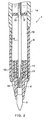
FIG.3 is a longitudinal cross-sectional view of a writing instrument according to a first embodiment of the present invention; -
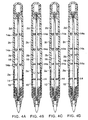
FIGs.4A to 4D are longitudinal cross-sectional views of the writing instrument to explain sequential operations in the first embodiment; -
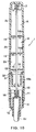
FIGs.5A and 5B are longitudinal cross-sectional views of the writing instrument to explain sequential operations in the first embodiment, and illustrate a first small chamber serving as a reservoir chamber; -
FIG.6 is a longitudinal cross-sectional view of a writing instrument according to a second embodiment of the present invention; -
FIG.7 is a longitudinal cross-sectional view of a writing instrument according to a third embodiment of the present invention; -
FIG.8 is a longitudinal cross-sectional view of a writing instrument according to a fourth embodiment of the present invention; -
FIG.9 is a longitudinal cross-sectional view of a writing instrument according to a fifth embodiment of the present invention; -
FIG.10 is a longitudinal cross-sectional view of a writing instrument according to a sixth embodiment of the present invention; -
FIG.11 is a longitudinal cross-sectional view of a writing instrument according to a seventh embodiment of the present invention; -
FIG.12A is a longitudinal cross-sectional view of a writing instrument according to an eighth embodiment of the present invention, andFIG.12B is a cross-sectional view taken along line XIIB-XIIB ofFIG.12A ; -
FIG.13 is a longitudinal cross-sectional view showing an example of a production method of the writing instrument according to the eighth embodiment; -
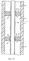
FIG.14 is an enlarged longitudinal cross-sectional view of part of the writing instrument according to a ninth embodiment of the present invention; -
FIG.15 is an enlarged longitudinal cross-sectional view of part of the writing instrument according to a tenth embodiment of the present invention; -
FIG.16 is an enlarged longitudinal cross-sectional view of part of the writing instrument according to an eleventh embodiment of the present invention; -
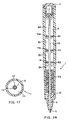
FIG.17 is a cross-sectional view taken along line XVII-XVII ofFIG.3 ; and -
FIG. 18 is a longitudinal cross-sectional view of a writing instrument having a bellows-shaped feeder mechanism. - Embodiments of the present invention will be described below with reference to accompanying drawings .
- First, with reference to
FIGs.1 and2 , basic principles of a writing instrument (basic principles of gas-liquid exchange/feeder type) according to the present invention will be described. -
FIGs.1 and2 illustrate a writing instrument provided with a ball chip using water-soluble ink. In the figures, reference numeral "1" denotes a barrel of the writing instrument, i.e., a main body of the writing instrument. - A
wall 14 is provided inside themain body 1 in the direction perpendicular to the axis direction. A portion at a tail end side partitioned by thewall 14 is configured to be a cylinder-shapedink chamber 2 with ink A filled therein and areservoir chamber 10 with a front end side in the form of a cylinder. Thewall 14 is configured by pressing a disk-shaped member inside themain body 1, and is provided with a throughhole 15 at its center portion. - The
main body 1 is provided with anend plug 3 at its tail end portion, and is further provided with achip ball holder 4 at its front end portion. The front end portion of thechip holder 4 is provided with aball chip 5 for water-soluble ink. Arubber boot 6 for anti-skid is provided on the outer periphery of the front end portion of themain body 1. - An upper end portion of the
chip holder 4 is formed in the shape of a cup, inserted into themain body 1, and forms anink receiving portion 11 of thereservoir chamber 10. A bottom of the receivingportion 11 is provided with a porousink holding member 13 made of a fiber material, and thus formed to impregnate ink therewith to hold. In addition, in the present invention, theink holding member 13 does not need to be provided in particular, and is not limited in structure to a porous member composed of a fiber material even if themember 13 is provided. - On the outer periphery of the receiving
portion 11 of thechip holder 4 is formed a groove extending in the axis direction. The groove forms anatmosphere communication passage 12 that causes the inner periphery of themain body 1 to communicate with the atmosphere. Thus, thereservoir chamber 10 communicates with the atmosphere through theatmosphere communication passage 12. Theatmosphere communication passage 12 is configured to prevent the ink in thereservoir chamber 10 from leaking outside. In this case, by providing the porousink holding member 13 inside thereservoir chamber 10, the ink having flowed in the reservoir chamber is impregnated and held in the ink holding member, and assuredly prevented from leaking from theatmosphere communication passage 12 to the outside. - Inside the
main body 1 is provided anink supply member 16 along the axis direction. Theink supply member 16 is a member referred to a relay core, composed of a porous rod-shaped member made of a large number of fibers gathered and compressed parallel to the axis direction, and supplies the ink by capillary force. In addition, members referred to a relay core include one obtained by applying water-non-permeable coating to the outer periphery of a fiber-gathered member as described above. However, in the structural example illustrated in the figure, the member without water-non-permeable coating on its outer periphery is used, and thus is capable of absorbing the ink from the outer periphery. - Accordingly, in this structural example, the ink is capable of flowing in and out through the periphery of the
ink supply member 16 over its entire length. The ink is reliably and stably supplied from theink chamber 2 to writingelement 5 by capillary force, and since the porous relay core itself has the ink flow rate adjusting function, it is possible to supply the ink stably. - The
ink supply member 16 is provided substantially over the entire length along the center axis line of themain body 1, and the front end portion of themember 16 is held in a holdinghole 18 formed in thechip holder 4 with a gap of some extent. A tail end portion of theink supply member 16 is engaged and held in a holdingmember 17 formed in the tail end portion of themain body 1. - A middle portion of the
ink supply member 16 penetrates theink chamber 2, throughhole 15 of thewall 14 andreservoir chamber 10. In this case, an inner diameter of the throughhole 15 of thewall 14 is formed to be a little larger than an outer diameter of theink supply member 16, and a predetermined circular gap G is prescribed between the outer periphery of theink supply member 16 and the inner periphery of the throughhole 15. - The gap G forms a communication hole capable of holding the ink due to capillary force. In this case, the size of the gap G is set as appropriate corresponding to, for example, type of ink to be used, and is usually set closed to prevent the air from entering.
- The operation of the writing instrument configured as described above will be described.
- Usually, the gap G of the
wall 14 is sealed with an ink membrane. Accordingly, even when the writing instrument is in a substantially vertical posture with the writing element directed downward, the ink does not flow from the gap G. - The ink A in the
ink chamber 2 is supplied to theball chip 5 through theink supply member 16, thereby enabling writing. Then, when the ink in theink chamber 2 is consumed by writing, the pressure inside theink chamber 2 becomes a negative pressure. By this negative pressure, the seal of the ink membrane held in the gap G is broken, a small amount of air conforming to the consumed amount is led to theink chamber 2 from thereservoir chamber 10 through the gap G, then the negative pressure inside theink chamber 2 is canceled, and the pressure is made equal to the atmospheric pressure. In response to this behavior, the gap G is sealed again with the ink membrane due to capillary force. - After the air is led into the
ink chamber 2, the air expands or contracts due to changes in temperature. In this case, when the led air contracts, the ink membrane held in the gap G is broken and the air is introduced similarly, thereby preventing theink chamber 2 from having a negative pressure. When the air in theink chamber 2 expands, due to the pressure, the ink membrane is broken and the ink is pushed out of the gap G to thereservoir chamber 10. The pushed-out ink is impregnated in theink holding member 13, and the ink held in theink holding member 13 is consumed by writing, or is returned to a side of theink chamber 2 through theink supply member 16 when the pressure inside theink chamber 2 becomes negative. Accordingly, an excess amount of ink does not stay in thereservoir chamber 10. - The writing instrument as described above has a simple structure without a variable portion, and therefore is easy in production, simple in operation principle, and high in reliability. In particular, the gap G between the through
hole 15 formed in the wall andink supply member 16 is only a portion for controlling introduction of air and exclusion of ink into/from theink chamber 2 for compensating for expansion and contraction due to ink consumption, changes in temperature, changes in barometric pressure in theink chamber 2. Further, the ink is always supplied to the gap G from theink chamber 2 andink supply member 16 to maintain the ink membrane. Accordingly, even when leaving the writing instrument unused for a long time, it does not happen that the ink in the gap G dries and thereby clogging occurs, and it is possible to secure remarkably stable operations. - Further, even when leaving the writing instrument standing with the writing element directed upward for a long time, since the ink is supplied into the gap G due to capillary force from the periphery surface of the porous
ink supply member 16 made of a fiber-gathered member and is held in the gap G, it does not happen that the ink in the gap G dries and thereby clogging occurs, and it is possible to obtain a stable seal characteristic and improved reliability. - Furthermore, the
ink chamber 2 is closed at its tail end side, and the gap G at the front end side of thechamber 2 is usually sealed with the ink membrane. Accordingly, even when letting the writing instrument stand in a posture as illustrated inFIG.1 in writing, the hydraulic pressure inside theink chamber 2 has little effect on theink supply member 16. Thus, the control is performed for ink stable supply. - Moreover, in this structural example, the porous
ink supply member 16 composed of the fiber-gathered member penetrates thereservoir chamber 10 communicating with the atmosphere with the outer periphery of themember 16 exposed, thus providing the function of compensating for changes in the hydraulic pressure in this portion or in other pressure. - The reasons for such a function have not been analyzed in detail currently, but there considered is that since the ink is held in the ink supply member by capillary force, and a free surface of the ink is formed on the outer periphery of the ink supply member and is in contact with the air in the reservoir chamber having a pressure equal to the atmospheric pressure, a pressure difference is difficult to occur inherently between the ink in the ink chamber and the atmosphere, and that since the ink contained in the ink supply member is in contact with the material composing the ink supply member in large surface area, the air is prevented by capillary force serving on the surface from entering, and even when a small pressure difference occurs due to the hydraulic pressure in the axis direction of the ink supply member, the pressure difference is not conveyed directly to the writing element.
- In the writing instrument with the above configuration, since the
ink chamber 2 is composed of a single space, an amount of air staying in theink chamber 2 is increased as the ink is consumed. Therefore, when an expansion amount of air is increased due to changes in temperature, an amount of ink pushed out to thereservoir chamber 10 is increased. - Specific embodiments using the above-mentioned operational principles according to the present invention will be described below. In addition, in embodiments of the present invention described later, members having the same function and effect as in the structural example illustrated in
FIGs.1 and2 are assigned the same reference numerals, and descriptions thereof are omitted or simplified. -
FIGs.3 ,4A to 4D ,5A and 5B illustrate the first embodiment of the present invention. - In this embodiment, the
ink chamber 2 is provided with a plurality of, for example, threewalls 14a, and is partitioned in the axis direction into a firstsmall chamber 2a, secondsmall chamber 2b, thirdsmall chamber 2c and fourthsmall chamber 2d. Thesewalls 14a have the same structure as that of thewall 14 which partitions theink chamber 2 and thereservoir chamber 10. Theink supply member 16 penetrates the throughhole 15 of eachwall 14a. Thus, theink chamber 2 is composed ofsmall chambers 2a to 2d partitioned in the axis direction. - The operation of the first embodiment will be described.
- In a first state of the writing instrument, as shown in
FIG.4A , all the firstsmall chamber 2a, secondsmall chamber 2b, thirdsmall chamber 2c and fourthsmall chamber 2d are filled with the ink A. - In this structure, when the ink is consumed by writing, as shown in
FIG.4B , the ink in the firstsmall chamber 2a where the gas-liquid exchange is performed with thereservoir chamber 10 is preferentially consumed, while the air is led into the firstsmall chamber 2a. Then, as shown inFIG.4C , when the ink in the firstsmall chamber 2a is all consumed, as shown inFIG.4D , the firstsmall chamber 2a functions as a reservoir chamber, the gas-liquid exchange is thereby performed in the secondsmall chamber 2b, and the ink in the secondsmall chamber 2b is consumed preferentially. In this way, the ink is consumed from the firstsmall chamber 2a to fourthsmall chamber 2d sequentially in this order, and the air is introduced. - According to this structure, when the air in the first
small chamber 2a expands, according to the operational principle as described above, the ink in the firstsmall chamber 2a is pushed to thereservoir chamber 10 and stays in thereservoir chamber 10. Then, as shown inFIG.5A , when the ink in the firstsmall chamber 2a is consumed and thechamber 2a is emptied, the air stays in the secondsmall chamber 2b. When the air in thechamber 2b expands, as shown inFIG.5B , the ink in the secondsmall chamber 2b is pushed to the firstsmall chamber 2a and stays in thechamber 2a. In other words, after the ink in the firstsmall chamber 2a is consumed, the firstsmall chamber 2a functions as a reservoir chamber, and similarly, the secondsmall chamber 2b and thirdsmall chamber 2c function as a reservoir chamber sequentially. - Thus, the
ink chamber 2 is divided into small chambers which function as a reservoir chamber sequentially in ascending order of height of a chamber position as the ink is consumed, whereby the need of increasing the capacity of thereservoir chamber 10 is eliminated. In other words, since the capacity of the firstsmall chamber 2a is small, an amount of ink pushed out of thechamber 2a is also small, and therefore, the capacity of thereservoir chamber 10 is made small. As a result, corresponding to the decreased capacity, it is possible to increase the entire capacity of theink chamber 2, and to increase an amount of ink to store. -
FIG.6 is a view illustrating the second embodiment of the present invention. In this embodiment, afelt chip 5a is provided as a writing element. Thus, the present invention is not limited in writing element communicating with the ink supply member, and it is possible to attach various types of writing elements. -
FIG.7 is a view illustrating the third embodiment of the present invention. In this embodiment, the front end portion of the porousink supply member 16 extends, and forms a feltchip portion 5b. In this way, a writing element can be formed integrally from the material of theink supply member 16, and such a construction simplifies the structure. -
FIG.8 is a view illustrating the fourth embodiment of the present invention. In this embodiment, theink chamber 2 is partitioned into three chambers with two walls, and theink holding member 13 is not provided. The writing element is composed of a feltchip 5c with a thick diameter suitable for writing instruments providing thick handwriting such as a white board marker pen. - In this embodiment, since the ink holding member is not provided, the
atmosphere communication passage 12 communicating with thereservoir chamber 10 is formed in a side wall of the main body of the writing instrument, thereby preventing the ink pushed to thereservoir chamber 10 from leaking outside. - Thus, it is possible to modify as appropriate the number of small chambers partitioned in the ink chamber, composition of a writing element, and position in which an atmosphere communication passage is formed.
- Further, in this embodiment, since a large amount of ink is consumed, the capacity of the
ink chamber 2 is increased. In response to this, capacities of the firstsmall chamber 2a and secondsmall chamber 2b are small, and the capacity of thethird chamber 2c is large. In this way, an amount of ink pushed out of thefirst chamber 2a is deceased so as to decrease the capacity of theink reservoir chamber 10. In this case, among the small chambers composing thereservoir chamber 10 andink chamber 2, one or more chambers at the writing element side are small, and the others are made larger as the chamber is spaced a more distance away from the writing element. It is thereby possible to effectively increase the capacity of theink chamber 2. -
FIG.9 is a view illustrating the fifth embodiment of the present invention. In this embodiment, a cup-shapedink holding member 13a is provided in thereservoir chamber 10 to be in intimate contact with thewall 14. An upper portion of the cup-shapedink holding member 13a is provided with acommunication hole 30, thereby causing thereservoir chamber 10 to communicate with the inside of theink holding member 13a. - According to this structure, since the ink pushed out of the first
small chamber 2a stays in the cup-shapedink holding member 13a, the ink is assuredly prevented from leaking outside. Therefore, despite theatmosphere communication passage 12 communicating with thereservoir chamber 10 being formed in a side portion of thewriting element 5c in the vertical direction, the ink does not leak from thepassage 12. -
FIG.10 is a view illustrating the sixth embodiment of the present invention. In this embodiment, a cup-shapedink holding member 13b is provided in thereservoir chamber 10 to be spaced a predetermined distance away from thewall 14. Acommunication groove 32 is formed on the outer periphery of anupper end portion 31 of the cup-shapedink holding member 13b, thereby causing thereservoir chamber 10 to communicate with the inside of theink holding member 13b. - Also in such a structure, since the ink pushed out of the first
small chamber 2a stays in the cup-shapedink holding member 13b, the ink is assuredly prevented from leaking outside. -
FIG.11 is a view illustrating the seventh embodiment of the present invention. In this embodiment, in thereservoir chamber 10 is provided a cup-shapedink holding member 13c that maintains the sealing and is slidable in the axis direction. - According to this structure, since the ink pushed out of the first
small chamber 2a stays in the cup-shapedink holding member 13c, the ink is assuredly prevented from leaking outside. Further, when the air and/or ink expands/contracts in theink chamber 2 due to changes in temperature, the slidableink holding member 13c slides to compensate for the expansion/contraction. -
FIGs. 12A and 12B are views illustrating the eighth embodiment of the present invention. In this embodiment, the front end portion of the porousink supply member 16 extends, and forms the feltchip portion 5b. The inner diameter of a holdinghole 18a of thechip holder 4 is greater than the outer diameter of the ink supply member 16 (feltchip portion 5b), gaps H are formed between thehole 18a andmember 16, and thereservoir chamber 10 communicates with the atmosphere through the gaps H. Therefore, in this embodiment theatmosphere communication passage 12 as described previously is eliminated. Further, as shown inFIG.12B , on the inner periphery of a front end portion of the holdinghole 18a are provided a plurality of holding projectingportions 35 that project from the periphery and hold the feltchip portion 5a. - The gaps H usually hold the ink by capillary force and seal the
reservoir chamber 10. When a pressure difference occurs between thereservoir chamber 10 and atmosphere, the seal by the ink membrane is broken, and thechamber 10 communicates with the atmosphere. Accordingly, in the structure in this embodiment, since the gaps H are usually sealed, the ink is effectively prevented from drying. - Further, in this embodiment, the face of each of
walls hole 15. When filling the ink into the writing instrument, before theink supply member 16 is attached, as illustrated inFIG.13 , the ink is injected while holding the main body of the writing instrument substantially vertically with the front end side directed upward. In this case, since the face of thewall 14 at the tail plug side is tapered, the air is guided to the tapered face and assuredly exhausted, and any air bubble does not remain at lower portions ofwalls -
FIG.14 illustrates the ninth embodiment of the present invention, and is a view illustrating enlarged portions of the ink chamber and reservoir chamber. In this embodiment, anink supply member 40 is composed of a rod-shapedrelay core 41 made of a porous material such as a fiber-gathered member and an ink-non-permeable coating 42 that is coated on the periphery surface of thecore 41. - Part of the
coating 42 is removed at portions opposed to the inner periphery of the throughhole 15 and in the vicinity of thehole 15 in each ofwalls communication portions 43 through which the ink flows. - According to this embodiment, despite the outer periphery surface of the ink supply member being ink-non-permeable, since
communication portions 43 are formed in and adjacent to the throughholes 15, the ink is capable of flowing from the ink chamber to the inside of the ink supply member throughcommunication portions 43, and the ink at small chambers is consumed in ascending order of height of a chamber position. Further, at portions in throughholes 15 are providedcommunication portions 43 where the rod-shapedrelay core 41 made of the porous material is exposed. Therefore, similarly to the above structures, the ink membrane is usually held in constant state in the gap G, thereby stabilizing characteristics, while it does not happen that the ink in the gap G dries and thereby clogging occurs, and it is thus possible to obtain high stability and reliability. - Further, since the
relay core 41 is coated with thecoating 42 exceptcommunication portions 43 in the gap G, it is possible to prevent a solvent of the ink from evaporating from the surface of theink supply member 40, for example, in thefeeder chamber 10. Accordingly, there are advantages in the case of using fast-drying ink. -
FIG.15 illustrates the tenth embodiment of the present invention, and is a view illustrating enlarged portions of the ink chamber and reservoir chamber. Anink supply member 50 of this embodiment is composed of a tube with a small diameter, andcommunication portions 51 through which the ink flows are formed at portions opposed to inner peripheries of throughholes 15 ofwalls -
FIG.16 illustrates the eleventh embodiment of the present invention, and is a view illustrating enlarged portions of the ink chamber and reservoir chamber. Also in this embodiment, theink supply member 50 is composed of a tube with a small diameter, andcommunication portions 51a are formed in the vicinities of throughholes 15 ofwalls - Also in the tenth and eleventh embodiments as described above, in the same way as in the ninth embodiment, it is possible to prevent a solvent of the ink from evaporating from the surface of the
ink supply member 50, for example, in thefeeder chamber 10. Accordingly, there are advantages in the case of using fast-drying ink. - In the case where the ink supply member is made of the porous materially with the coating as illustrated in
FIG.14 , or of a small-diameter tube as illustrated inFIGs.15 and16 , each ofcommunication portions - In the above-mentioned embodiments, each of communication holes formed on
walls ink supply member 16 and the inner periphery of the throughhole 15 through which themember 16 passes. -
FIG. 18 is a view illustrating an embodiment in which thereservoir chamber 10 accommodates a bellows-shapedfeeder mechanism 70. Thefeeder mechanism 70 has the same structure as that is used conventionally, where a plurality of disk-shaped members projects in the form of bellows from the center axis portion, and circular gaps between the members holds the ink due to capillary force. In this embodiment, since the reservoirs chamber is provided with the bellows-shapedfeeder mechanism 70, the pushed-out ink is held and returned reliably. Further, since the ink having flowed in thereservoir chamber 10 is held in the feeder mechanism, the ink is assuredly prevented from leaking outside from a passage causing the reservoir chamber to communicate with the atmosphere.Fig. 18 does not correspond to the invention so far asexcentric holes 62 are shown. - According to constitutions of the present invention, the present invention is applicable to small-sized writing instruments such as a refill-type of writing instrument and writing instrument accompanying a pocketbook, and further is applicable to disposable writing instruments and other general writing instruments.
Claims (7)
- A writing instrument comprising:an ink chamber (2) formed inside a main body (1) of the writing instrument;a writing element (5) provided on a front end portion of the main body (1) of the writing instrument;a reservoir chamber (10) which is formed between the ink chamber (2) and the writing element (5) and communicates with the atmosphere and with the writing element;a plurality of walls (14) which partitions the reservoir chamber (10) and the ink chamber (2) and further partitions the ink chamber (2) into a plurality of small chambers in the axis direction; andan ink supply member (16, 50) which penetrates the plurality of walls (14) and supplies ink from the ink chamber (2) to the writing element (5),wherein a through hole (15) through which the ink supply member (16, 50) passes is formed at a center portion of each of the walls (14), and a circular gap (G) capable of holding the ink by capillary force is formed between an inner periphery of the through hole (15) formed in each of the walls (14) and an outer periphery of the ink supply member (16, 50); characterized in that
the ink supply member
is a rod-shaped member (16) composed of a porous material, and has an ink-permeable surface on its periphery
or is a tube-shaped member (50) having a communication portion (51, 51a) formed in its wall at least in said gap (G) or in a position in the vicinity of the gap (G), and
gas-liquid exchange between the reservoir chamber (10) and the ink chamber (2) and between adjacent ink chambers is performed only through the circular gap (G) formed in each of the walls (14). - The writing instrument according to claim 1, wherein the writing element (5b) is formed integrally with the ink supply member (16).
- The writing instrument according to claim 1, wherein a clearance between the walls (14a) in the axis direction is small at a side of the writing instrument (5c), and is increased as being spaced apart from the side of the writing instrument.
- The writing instrument according to claim 1, wherein at least a face opposite to a side of the writing element (5b) of each of the walls (14a) is tapered towards the writing element and tilted towards the through hole (15).
- The writing instrument according to claim 1, wherein the reservoir chamber (10) is provided with a porous ink holding member (13) that holds ink having flowed out of the ink chamber (2).
- The writing instrument according to claim 1, wherein the reservoir chamber (10) is provided with a cup-shaped ink holding member (13b) that holds ink having flowed out of the ink chamber (2).
- The writing instrument according to claim 1, wherein the reservoir chamber (10) is provided with a bellows-shaped feeder mechanism (70).
Applications Claiming Priority (3)
| Application Number | Priority Date | Filing Date | Title |
|---|---|---|---|
| JP2000134915A JP3436728B2 (en) | 2000-05-08 | 2000-05-08 | Writing implement |
| JP2000134915 | 2000-05-08 | ||
| PCT/JP2001/002527 WO2001085471A1 (en) | 2000-05-08 | 2001-03-28 | Writing implement |
Publications (3)
| Publication Number | Publication Date |
|---|---|
| EP1281539A1 EP1281539A1 (en) | 2003-02-05 |
| EP1281539A4 EP1281539A4 (en) | 2007-02-14 |
| EP1281539B1 true EP1281539B1 (en) | 2008-12-03 |
Family
ID=18643100
Family Applications (1)
| Application Number | Title | Priority Date | Filing Date |
|---|---|---|---|
| EP01917511A Expired - Lifetime EP1281539B1 (en) | 2000-05-08 | 2001-03-28 | Writing implement |
Country Status (13)
| Country | Link |
|---|---|
| US (1) | US6607325B2 (en) |
| EP (1) | EP1281539B1 (en) |
| JP (1) | JP3436728B2 (en) |
| KR (1) | KR20010103641A (en) |
| CN (1) | CN1181982C (en) |
| AU (2) | AU2001244570A1 (en) |
| BR (1) | BR0101892A (en) |
| CA (1) | CA2346272A1 (en) |
| DE (1) | DE60136801D1 (en) |
| ES (1) | ES2203279B1 (en) |
| ID (1) | ID30107A (en) |
| TW (1) | TWI232182B (en) |
| WO (1) | WO2001085471A1 (en) |
Families Citing this family (29)
| Publication number | Priority date | Publication date | Assignee | Title |
|---|---|---|---|---|
| JP4859282B2 (en) * | 2001-05-02 | 2012-01-25 | 三菱鉛筆株式会社 | Direct liquid writing instrument |
| JP2003011580A (en) * | 2001-06-29 | 2003-01-15 | Mitsubishi Pencil Co Ltd | Manufacturing method of writing implement and ink occlusion body |
| WO2003018327A1 (en) * | 2001-08-23 | 2003-03-06 | Hics Corporation | Writing implement |
| KR20020046252A (en) * | 2002-04-27 | 2002-06-20 | 김명원 | a multi-tank style of a ball pen core |
| WO2003101759A1 (en) * | 2002-05-31 | 2003-12-11 | Hics Corporation | Writing implement |
| JP4518943B2 (en) * | 2002-06-24 | 2010-08-04 | 株式会社 ヒックス | Writing instrument |
| US20070274765A1 (en) * | 2003-06-26 | 2007-11-29 | Crayola Llc | Retractable writing instrument |
| US6964534B2 (en) | 2003-06-26 | 2005-11-15 | Binney & Smith Inc. | Retractable writing instrument |
| WO2005123416A1 (en) | 2004-06-22 | 2005-12-29 | Hori, Yayoi | Liquid feed device |
| JP4137963B2 (en) | 2006-09-08 | 2008-08-20 | 三菱鉛筆株式会社 | Writing instrument |
| US7850382B2 (en) * | 2007-01-18 | 2010-12-14 | Sanford, L.P. | Valve made from two materials and writing utensil with retractable tip incorporating same |
| US7488130B2 (en) | 2007-02-01 | 2009-02-10 | Sanford, L.P. | Seal assembly for retractable instrument |
| US8226312B2 (en) * | 2008-03-28 | 2012-07-24 | Sanford, L.P. | Valve door having a force directing component and retractable instruments comprising same |
| US8221012B2 (en) * | 2008-11-07 | 2012-07-17 | Sanford, L.P. | Retractable instruments comprising a one-piece valve door actuating assembly |
| US8393814B2 (en) * | 2009-01-30 | 2013-03-12 | Sanford, L.P. | Retractable instrument having a two stage protraction/retraction sequence |
| CN102120394A (en) * | 2010-12-30 | 2011-07-13 | 林鹏贵 | Pen |
| CN105196735B (en) | 2015-09-07 | 2017-09-29 | 宁波五云笔业有限公司 | A kind of direct-fluid-supply writing implement |
| CN105882206B (en) * | 2016-04-21 | 2018-02-16 | 宁波五云笔业有限公司 | The writing implement of the resistance to temperature difference and pressure difference |
| EP3445593B1 (en) | 2016-04-21 | 2024-07-17 | Milwaukee Electric Tool Corporation | Internal pressure regulating marker pen |
| CN106142904A (en) * | 2016-08-31 | 2016-11-23 | 王海龙 | Auto-feeding writing brush |
| CN106274151A (en) * | 2016-08-31 | 2017-01-04 | 王海龙 | Auto-feeding writing brush |
| RU2731189C1 (en) * | 2016-12-20 | 2020-08-31 | Колгейт-Палмолив Компани | Personal hygiene device with fluid delivery system |
| CN106739648B (en) * | 2017-02-28 | 2018-03-16 | 温岭市志创网络科技有限公司 | A liquid pen that can continue to be used in a supine position |
| CN108501569A (en) * | 2017-02-28 | 2018-09-07 | 莫里斯公司 | Telescopic writing implement |
| EP3424746B1 (en) | 2017-05-12 | 2021-05-19 | Qingdao Changlong Stationery CO., LTD | Direct liquid type writing tool |
| CN110561945B (en) * | 2018-06-06 | 2024-07-05 | 迈博高分子材料(宁波)有限公司 | Scribble instrument |
| JP7320829B2 (en) * | 2019-05-30 | 2023-08-04 | 株式会社呉竹 | pen |
| CN112855612B (en) * | 2021-01-12 | 2024-03-22 | 宜兴市宙斯泵业有限公司 | Large centrifugal pump with lining not easy to tear |
| US12565045B2 (en) | 2023-03-15 | 2026-03-03 | Brady Worldwide, Inc. | Hydrophilic foam having improved fluid retention |
Family Cites Families (13)
| Publication number | Priority date | Publication date | Assignee | Title |
|---|---|---|---|---|
| GB204311A (en) | 1922-09-20 | 1924-05-22 | Maschf Augsburg Nuernberg Ag | Improvements in or relating to driving arrangements for rotary printing machines |
| FR2546823B1 (en) * | 1983-06-03 | 1989-02-17 | Pilot Pen Co Ltd | FEATHER CORE FOR A WRITING INSTRUMENT |
| US4770558A (en) * | 1986-02-20 | 1988-09-13 | Gebr. Schmidt KG Fabrik Fuer Feinmechanik | Ink writing or drawing instrument |
| DE3772608D1 (en) | 1986-04-10 | 1991-10-10 | Jiro Hori | DEVICE, FOR EXAMPLE, PEN, FOR APPLYING LIQUID. |
| DE69125774T2 (en) | 1990-09-11 | 1997-07-31 | Jiro Hori | Marker |
| DE4115685C3 (en) * | 1991-05-14 | 2001-07-05 | Dataprint Datendrucksysteme R | Writing instrument with writing fluid freely contained in a container |
| JP2679918B2 (en) | 1992-02-17 | 1997-11-19 | 二郎 堀 | Writing implement |
| DE69400081T2 (en) | 1993-04-26 | 1996-07-25 | Jiro Hori | Writing instrument |
| JP2534821B2 (en) * | 1993-05-13 | 1996-09-18 | 二郎 堀 | Writing instrument |
| DE19529865C2 (en) * | 1995-08-14 | 2002-02-28 | Kaufmann R Dataprint | Device for applying liquids to a base by means of an application element |
| DE69932933T2 (en) * | 1998-05-01 | 2007-08-30 | Mitsubishi Pencil K.K. | WRITING INSTRUMENT |
| CN1328507A (en) | 1998-11-27 | 2001-12-26 | 株式会社黑库斯 | Writing instrument and method of producing the same |
| DE19948477A1 (en) * | 1999-10-08 | 2001-04-12 | Dataprint R Kaufmann Gmbh | Device for applying writing, drawing, printing, painting fluid or the like on a surface |
-
2000
- 2000-05-08 JP JP2000134915A patent/JP3436728B2/en not_active Expired - Lifetime
-
2001
- 2001-03-28 DE DE60136801T patent/DE60136801D1/en not_active Expired - Lifetime
- 2001-03-28 AU AU2001244570A patent/AU2001244570A1/en not_active Abandoned
- 2001-03-28 CN CNB018091512A patent/CN1181982C/en not_active Expired - Lifetime
- 2001-03-28 WO PCT/JP2001/002527 patent/WO2001085471A1/en not_active Ceased
- 2001-03-28 EP EP01917511A patent/EP1281539B1/en not_active Expired - Lifetime
- 2001-04-26 BR BR0101892-2A patent/BR0101892A/en not_active Application Discontinuation
- 2001-05-01 AU AU40280/01A patent/AU4028001A/en not_active Abandoned
- 2001-05-01 ID IDP00200100355D patent/ID30107A/en unknown
- 2001-05-04 TW TW090110738A patent/TWI232182B/en not_active IP Right Cessation
- 2001-05-04 KR KR1020010024310A patent/KR20010103641A/en not_active Ceased
- 2001-05-04 ES ES200101021A patent/ES2203279B1/en not_active Expired - Lifetime
- 2001-05-04 CA CA002346272A patent/CA2346272A1/en not_active Abandoned
-
2002
- 2002-10-30 US US10/283,962 patent/US6607325B2/en not_active Expired - Lifetime
Also Published As
| Publication number | Publication date |
|---|---|
| CA2346272A1 (en) | 2001-11-08 |
| EP1281539A1 (en) | 2003-02-05 |
| US20030068191A1 (en) | 2003-04-10 |
| AU2001244570A1 (en) | 2001-11-20 |
| JP2001315483A (en) | 2001-11-13 |
| KR20010103641A (en) | 2001-11-23 |
| WO2001085471A1 (en) | 2001-11-15 |
| CN1427777A (en) | 2003-07-02 |
| EP1281539A4 (en) | 2007-02-14 |
| ID30107A (en) | 2001-11-08 |
| CN1181982C (en) | 2004-12-29 |
| ES2203279B1 (en) | 2005-06-16 |
| JP3436728B2 (en) | 2003-08-18 |
| US6607325B2 (en) | 2003-08-19 |
| BR0101892A (en) | 2001-12-18 |
| AU4028001A (en) | 2001-11-15 |
| ES2203279A1 (en) | 2004-04-01 |
| TWI232182B (en) | 2005-05-11 |
| DE60136801D1 (en) | 2009-01-15 |
Similar Documents
| Publication | Publication Date | Title |
|---|---|---|
| US6607325B2 (en) | Writing instrument | |
| JP2534821B2 (en) | Writing instrument | |
| EP1780046B1 (en) | Liquid feed device | |
| KR101130901B1 (en) | Writing tool | |
| CN111183041B (en) | Coating tool | |
| US6322269B1 (en) | Free ink system | |
| JP2018114705A (en) | Applicator | |
| JP4518943B2 (en) | Writing instrument | |
| US20040170465A1 (en) | Free ink system | |
| US3533708A (en) | Ball point pen for water soluble ink | |
| US6632041B1 (en) | Free ink system | |
| JP3861213B2 (en) | Ink introduction tube and writing instrument incorporating the same | |
| CN113556961A (en) | Coating tool | |
| CN102145613A (en) | Direct-liquid type writing tool | |
| JP2002326488A (en) | Writing utensil | |
| WO2003101759A1 (en) | Writing implement | |
| EP1775143B1 (en) | Free ink system | |
| WO1999012751A1 (en) | Writing utensil | |
| KR20010023863A (en) | Writing Utensil | |
| JP2002283785A (en) | Liquid supply tool | |
| JP2004330710A (en) | Liquid container | |
| JP2000313190A (en) | Writing implement |
Legal Events
| Date | Code | Title | Description |
|---|---|---|---|
| PUAI | Public reference made under article 153(3) epc to a published international application that has entered the european phase |
Free format text: ORIGINAL CODE: 0009012 |
|
| 17P | Request for examination filed |
Effective date: 20021106 |
|
| AK | Designated contracting states |
Designated state(s): AT BE CH CY DE DK ES FI FR GB GR IE IT LI LU MC NL PT SE TR |
|
| AX | Request for extension of the european patent |
Extension state: AL LT LV MK RO SI |
|
| RBV | Designated contracting states (corrected) |
Designated state(s): DE FR GB |
|
| A4 | Supplementary search report drawn up and despatched |
Effective date: 20070116 |
|
| RIC1 | Information provided on ipc code assigned before grant |
Ipc: B43K 5/02 20060101AFI20070110BHEP Ipc: B43K 7/02 20060101ALI20070110BHEP Ipc: B43K 8/03 20060101ALI20070110BHEP |
|
| 17Q | First examination report despatched |
Effective date: 20070615 |
|
| GRAP | Despatch of communication of intention to grant a patent |
Free format text: ORIGINAL CODE: EPIDOSNIGR1 |
|
| GRAS | Grant fee paid |
Free format text: ORIGINAL CODE: EPIDOSNIGR3 |
|
| GRAA | (expected) grant |
Free format text: ORIGINAL CODE: 0009210 |
|
| AK | Designated contracting states |
Kind code of ref document: B1 Designated state(s): DE FR GB |
|
| REG | Reference to a national code |
Ref country code: GB Ref legal event code: FG4D |
|
| REF | Corresponds to: |
Ref document number: 60136801 Country of ref document: DE Date of ref document: 20090115 Kind code of ref document: P |
|
| PLBE | No opposition filed within time limit |
Free format text: ORIGINAL CODE: 0009261 |
|
| STAA | Information on the status of an ep patent application or granted ep patent |
Free format text: STATUS: NO OPPOSITION FILED WITHIN TIME LIMIT |
|
| 26N | No opposition filed |
Effective date: 20090904 |
|
| REG | Reference to a national code |
Ref country code: GB Ref legal event code: 732E Free format text: REGISTERED BETWEEN 20110113 AND 20110119 |
|
| REG | Reference to a national code |
Ref country code: DE Ref legal event code: R081 Ref document number: 60136801 Country of ref document: DE Owner name: 3S CORP., JP Free format text: FORMER OWNER: HICS CORP., SAITAMA, JP Effective date: 20110224 |
|
| REG | Reference to a national code |
Ref country code: FR Ref legal event code: TP Owner name: YAYOI HORI, JP Effective date: 20110914 |
|
| REG | Reference to a national code |
Ref country code: DE Ref legal event code: R082 Ref document number: 60136801 Country of ref document: DE Representative=s name: V. BEZOLD & PARTNER, DE |
|
| REG | Reference to a national code |
Ref country code: DE Ref legal event code: R081 Ref document number: 60136801 Country of ref document: DE Owner name: 3S CORP., JP Free format text: FORMER OWNER: HORI, YAYOI, SAKADO-SHI, JP Effective date: 20130311 Ref country code: DE Ref legal event code: R082 Ref document number: 60136801 Country of ref document: DE Representative=s name: V. BEZOLD & PARTNER, DE Effective date: 20130311 Ref country code: DE Ref legal event code: R082 Ref document number: 60136801 Country of ref document: DE Representative=s name: V. BEZOLD & PARTNER PATENTANWAELTE - PARTG MBB, DE Effective date: 20130311 Ref country code: DE Ref legal event code: R081 Ref document number: 60136801 Country of ref document: DE Owner name: 3S CORP., JP Free format text: FORMER OWNER: HORI, YAYOI, SAKADO-SHI, SAITAMA, JP Effective date: 20130311 |
|
| REG | Reference to a national code |
Ref country code: FR Ref legal event code: TP Owner name: 3S CORPORATION, JP Effective date: 20130429 |
|
| REG | Reference to a national code |
Ref country code: GB Ref legal event code: 732E Free format text: REGISTERED BETWEEN 20130606 AND 20130612 |
|
| REG | Reference to a national code |
Ref country code: FR Ref legal event code: PLFP Year of fee payment: 16 |
|
| REG | Reference to a national code |
Ref country code: FR Ref legal event code: PLFP Year of fee payment: 17 |
|
| REG | Reference to a national code |
Ref country code: FR Ref legal event code: PLFP Year of fee payment: 18 |
|
| PGFP | Annual fee paid to national office [announced via postgrant information from national office to epo] |
Ref country code: DE Payment date: 20200320 Year of fee payment: 20 Ref country code: GB Payment date: 20200323 Year of fee payment: 20 |
|
| PGFP | Annual fee paid to national office [announced via postgrant information from national office to epo] |
Ref country code: FR Payment date: 20200319 Year of fee payment: 20 |
|
| REG | Reference to a national code |
Ref country code: DE Ref legal event code: R071 Ref document number: 60136801 Country of ref document: DE |
|
| REG | Reference to a national code |
Ref country code: GB Ref legal event code: PE20 Expiry date: 20210327 |
|
| PG25 | Lapsed in a contracting state [announced via postgrant information from national office to epo] |
Ref country code: GB Free format text: LAPSE BECAUSE OF EXPIRATION OF PROTECTION Effective date: 20210327 |