EP1281217B1 - Rotary electric contactor - Google Patents
Rotary electric contactor Download PDFInfo
- Publication number
- EP1281217B1 EP1281217B1 EP01929772A EP01929772A EP1281217B1 EP 1281217 B1 EP1281217 B1 EP 1281217B1 EP 01929772 A EP01929772 A EP 01929772A EP 01929772 A EP01929772 A EP 01929772A EP 1281217 B1 EP1281217 B1 EP 1281217B1
- Authority
- EP
- European Patent Office
- Prior art keywords
- conductor
- ribbon
- foam
- contactor
- ribbon conductor
- Prior art date
- Legal status (The legal status is an assumption and is not a legal conclusion. Google has not performed a legal analysis and makes no representation as to the accuracy of the status listed.)
- Expired - Lifetime
Links
Images


Classifications
-
- B—PERFORMING OPERATIONS; TRANSPORTING
- B60—VEHICLES IN GENERAL
- B60R—VEHICLES, VEHICLE FITTINGS, OR VEHICLE PARTS, NOT OTHERWISE PROVIDED FOR
- B60R16/00—Electric or fluid circuits specially adapted for vehicles and not otherwise provided for; Arrangement of elements of electric or fluid circuits specially adapted for vehicles and not otherwise provided for
- B60R16/02—Electric or fluid circuits specially adapted for vehicles and not otherwise provided for; Arrangement of elements of electric or fluid circuits specially adapted for vehicles and not otherwise provided for electric constitutive elements
- B60R16/023—Electric or fluid circuits specially adapted for vehicles and not otherwise provided for; Arrangement of elements of electric or fluid circuits specially adapted for vehicles and not otherwise provided for electric constitutive elements for transmission of signals between vehicle parts or subsystems
- B60R16/027—Electric or fluid circuits specially adapted for vehicles and not otherwise provided for; Arrangement of elements of electric or fluid circuits specially adapted for vehicles and not otherwise provided for electric constitutive elements for transmission of signals between vehicle parts or subsystems between relatively movable parts of the vehicle, e.g. between steering wheel and column
-
- H—ELECTRICITY
- H01—ELECTRIC ELEMENTS
- H01R—ELECTRICALLY-CONDUCTIVE CONNECTIONS; STRUCTURAL ASSOCIATIONS OF A PLURALITY OF MUTUALLY-INSULATED ELECTRICAL CONNECTING ELEMENTS; COUPLING DEVICES; CURRENT COLLECTORS
- H01R35/00—Flexible or turnable line connectors, i.e. the rotation angle being limited
- H01R35/02—Flexible line connectors without frictional contact members
Definitions
- the present invention relates to a rotary electrical contactor comprising a conductive tape.
- Rotary contactors are devices for electrically connecting parts pivoting with respect to each other.
- the ribbon conductor is enclosed in a housing which is delimited in particular by two parallel plates against which the upper edges and ribbon conductor support.
- One end of the ribbon conductor is attached to a stator which is located general at the periphery of the contactor.
- the other end of the ribbon conductor is connected to a rotor, most often housed inside the stator.
- the present invention aims to provide an efficient and economical solution to these problems.
- the present invention relates to a rotary electrical contactor comprising a ribbon conductor held by one of its edges against at least one coated plate of an insulating material on its face directed towards said tape conductor, characterized in that that the insulating material is foam and that the edge of the tape conductor is rounded and applied directly against this foam.
- the ribbon conductor can be put in direct contact with a foam coating covering the plates of the contactor.
- the foam is presented under the shape of a non-adhesive sheet sandwiched between the tape conductor and the plate. His low weight allows it to be left free between the conductor's edge and the face of the plate directed towards the conductor.
- the foam sheet can also be glued to the plate.
- different techniques can be used.
- One of them consists of enclosing conductive strips in a sheet of plastic material folded back on itself and forming a rounded edge at each conductor-song.
- extrusion a technique by which the conductive strips are directly coated with extruded plastic.
- extrusion a technique by which the conductive strips are directly coated with extruded plastic.
- the contactor shown in the drawing comprises, in known manner, a housing 1 in cup-shaped, pierced in the middle by an orifice 2 in which is housed a lower hub 3.
- the contactor also includes a cover 4 which is formed in one piece with an upper hub 5 extending over the entire height of the housing.
- the cover 4 fits into the housing 1, inside which it is retained by latching with the lower hub 3.
- This snap-in ensures the axial retention of the cover but leaves the latter free to pivot inside the case, accompanying a rotating shaft, as by example a shaft of a steering column supporting a steering wheel.
- the outer end 8 of the ribbon conductor is fixed to a terminal 9 integral with the housing.
- the inner end 10 of the ribbon conductor is fixed to a terminal 11 integral cover 4.
- the bottom 12 of the housing and the inner face 13 of the cover constitute plates parallels between which the ribbon conductor 7 is held, inside the cage ring finger 6.
- the bottom 12 of the housing and the inner face 13 of the cover are coated with a sheet polyurethane, polyethylene or polypropylene foam 14.
- Each foam sheet 14 is left free in the cage 6.
- the ribbon conductor 7 maintains it in the vicinity of the corresponding plate 12, 13.
- the edges of the ribbon conductor directed, one towards the cover, the other towards the bottom of the case are rounded in the direction where they have no sharp edges.
- the rounded shape of the edge is enough to prevent the foam from deteriorating or ribbon conductor blocking.
- This ribbon conductor comprises four conductive strips 15, for example in copper, overmolded in a mass 16 of polyester after extrusion. Songs 17 of the mass are rounded off by an appropriate choice of the extrusion head.
- This ribbon conductor comprises six conductive strips 18 which have been deposited on a polyester sheet laid flat.
- the polyester sheet has been folded back on itself on either side of the strips conductive to enclose them completely, the ends 20 of the sheet joining substantially in the middle of the ribbon.
- the sheet thus prepared was subjected to hot pressing, which formed bridges 21 between the conductive strips, thus providing insulation and positioning definitive of these.
- edges 22 of the ribbon thus obtained are rounded, that is to say they do not have no sharp edges.
Landscapes
- Engineering & Computer Science (AREA)
- Mechanical Engineering (AREA)
- Steering Controls (AREA)
- Push-Button Switches (AREA)
- Installation Of Indoor Wiring (AREA)
- Elimination Of Static Electricity (AREA)
Description
La présente invention concerne un contacteur électrique tournant comprenant un conducteur-ruban.The present invention relates to a rotary electrical contactor comprising a conductive tape.
Les contacteurs tournants sont des dispositifs permettant de relier électriquement des pièces pivotant les unes par rapport aux autres.Rotary contactors are devices for electrically connecting parts pivoting with respect to each other.
On les utilise en particulier dans les colonnes de direction des véhicules automobiles, pour relier des organes électriques montés sur le volant à des appareillages fixés sur le véhicule.They are used in particular in vehicle steering columns automobiles, for connecting electrical components mounted on the steering wheel to switchgear attached to the vehicle.
Dans ce type de dispositif, le conducteur-ruban est enfermé dans un boítier qui est délimité notamment par deux plaques parallèles contre lesquelles les chants supérieur et inférieur du conducteur-ruban prennent appui.In this type of device, the ribbon conductor is enclosed in a housing which is delimited in particular by two parallel plates against which the upper edges and ribbon conductor support.
L'une des extrémités du conducteur-ruban est fixée à un stator qui se trouve en général à la périphérie du contacteur. L'autre extrémité du conducteur-ruban est reliée à un rotor, logé le plus souvent à l'intérieur du stator.One end of the ribbon conductor is attached to a stator which is located general at the periphery of the contactor. The other end of the ribbon conductor is connected to a rotor, most often housed inside the stator.
Dans les contacteurs tournants connus, on a déjà constaté le défaut consistant en ce que le conducteur-ruban vibre et/ou frotte contre les plaques parallèles entre lesquelles il est maintenu, ce qui engendre des bruits indésirables.In known rotary contactors, the fault consisting of what the ribbon conductor vibrates and / or rubs against the parallel plates between which it is maintained, which generates unwanted noise.
Différentes solutions ont déjà été proposées pour essayer de résoudre ce problème. L'une d'elles consiste à revêtir les faces des plaques parallèles dirigées vers le conducteur-ruban de complexes constitués de mousse et d'un film glissant qui remplissent la double fonction d'amortir les vibrations du ruban et d'éviter la friction de ses chants avec les plaques.Different solutions have already been proposed to try to solve this problem. One of them consists in coating the faces of the parallel plates directed towards the conductor-ribbon of complexes consisting of foam and a sliding film which perform the dual function of dampening the vibrations of the ribbon and avoiding the friction of its songs with the plates.
Cependant, cette solution s'avère relativement coûteuse et ne donne pas entière satisfaction, notamment en ce qui concerne les vibrations.However, this solution is relatively expensive and does not give an entire satisfaction, especially with regard to vibrations.
Une autre solution connue consiste à remplacer les complexes par des feuilles de feutrine, ce qui améliore en particulier l'amortissement des vibrations, mais cette solution présente l'inconvénient que la feutrine finit par pelucher. Un tel contacteur électrique tournant est mentionné, par exemple, dans le document EP-A-0 675 576.Another known solution consists in replacing the complexes with sheets of felt, which in particular improves vibration damping, but this solution has the disadvantage that the felt ends up fluffing. Such a rotary electrical contactor is mentioned, for example, in document EP-A-0 675 576.
La présente invention vise à fournir une solution efficace et économique à ces problèmes.The present invention aims to provide an efficient and economical solution to these problems.
La présente invention a pour objet un contacteur électrique tournant comprenant un conducteur-ruban maintenu par un de ses chants contre au moins une plaque revêtue d'un matériau isolant sur sa face dirigée vers ledit conducteur-ruban, caractérisé en ce que le matériau isolant est une mousse et en ce que le chant du conducteur-ruban est arrondi et s'applique directement contre cette mousse. The present invention relates to a rotary electrical contactor comprising a ribbon conductor held by one of its edges against at least one coated plate of an insulating material on its face directed towards said tape conductor, characterized in that that the insulating material is foam and that the edge of the tape conductor is rounded and applied directly against this foam.
Grâce à l'invention, il n'est plus nécessaire de prévoir, sur la ou les plaques du contacteur, un complexe mousse - film qui grève considérablement le prix de revient d'un contacteur électrique tournant traditionnel ou une feuille de feutrine qui est susceptible de se dégrader.Thanks to the invention, it is no longer necessary to provide, on the plate or plates of the contactor, a foam - film complex which considerably increases the cost price of a traditional rotary electrical contactor or a sheet of felt which is likely to degrade.
En effet, grâce à la forme arrondie de ses chants, le conducteur-ruban peut être mis en contact direct avec un revêtement en mousse recouvrant les plaques du contacteur.Indeed, thanks to the rounded shape of its edges, the ribbon conductor can be put in direct contact with a foam coating covering the plates of the contactor.
En outre, par la suppression du film glissant recouvrant la mousse des contacteurs de l'état de la technique, on améliore l'efficacité de la mousse comme amortisseur de vibrations.In addition, by removing the sliding film covering the contactor foam from the state of the art, the efficiency of the foam as a shock absorber is improved. vibration.
Dans un mode de réalisation particulier de l'invention, la mousse se présente sous la forme d'une feuille non adhésive intercalée entre le conducteur-ruban et la plaque. Son faible poids autorise en effet de la laisser libre entre le chant du conducteur et la face de la plaque dirigée vers le conducteur.In a particular embodiment of the invention, the foam is presented under the shape of a non-adhesive sheet sandwiched between the tape conductor and the plate. His low weight allows it to be left free between the conductor's edge and the face of the plate directed towards the conductor.
En cas de nécessité, la feuille de mousse peut aussi être collée à la plaque. Pour réaliser le chant arrondi du conducteur-ruban, différentes techniques peuvent être utilisées.If necessary, the foam sheet can also be glued to the plate. To achieve the rounded edge of the ribbon conductor, different techniques can be used.
L'une d'elles consiste à enfermer des bandes conductrices dans une feuille en matière plastique rabattue sur elle-même et formant un bord arrondi au niveau de chaque chant du conducteur-ruban.One of them consists of enclosing conductive strips in a sheet of plastic material folded back on itself and forming a rounded edge at each conductor-song.
Une autre technique, particulièrement avantageuse dans le cadre de la présente invention, est l'extrusion, technique par laquelle les bandes conductrices sont directement enrobées de matière plastique extrudée. Une telle technique est décrite dans EP-A-0 675 576.Another technique, particularly advantageous in the context of the present invention is extrusion, a technique by which the conductive strips are directly coated with extruded plastic. Such a technique is described in EP-A-0 675 576.
Afin de mieux faire comprendre l'invention, on va en décrire maintenant des modes de réalisation donnés à titre d'exemples non limitatifs, en référence au dessin annexé qui comprend :
- une figure 1 représentant une vue en coupe axiale d'un contacteur électrique selon un mode de réalisation de l'invention,
- une figure 2 représentant une vue en perspective éclatée du contacteur de la figure 1,
- une figure 3 représentant à plus grande échelle une coupe transversale du conducteur-ruban,
- une figure 4 représentant une section transversale d'un autre conducteur-ruban.
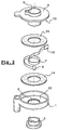
- FIG. 1 representing a view in axial section of an electrical contactor according to an embodiment of the invention,
- FIG. 2 representing an exploded perspective view of the contactor of FIG. 1,
- FIG. 3 representing on a larger scale a cross section of the ribbon conductor,
- Figure 4 showing a cross section of another ribbon conductor.
Le contacteur représenté sur le dessin comprend, de façon connue, un boítier 1 en
forme de coupelle, percé en son milieu par un orifice 2 dans lequel vient se loger un
moyeu inférieur 3.The contactor shown in the drawing comprises, in known manner, a
Le contacteur comprend également un couvercle 4 qui est formé d'un seul tenant
avec un moyeu supérieur 5 s'étendant sur toute la hauteur du boítier.The contactor also includes a
Le couvercle 4 s'emboíte dans le boítier 1, à l'intérieur duquel il est retenu par
encliquetage avec le moyeu inférieur 3.The
Cet encliquetage assure la rétention axiale du couvercle mais laisse ce dernier libre de pivoter à l'intérieur du boítier, en accompagnant un arbre tournant, comme par exemple un arbre d'une colonne de direction supportant un volant.This snap-in ensures the axial retention of the cover but leaves the latter free to pivot inside the case, accompanying a rotating shaft, as by example a shaft of a steering column supporting a steering wheel.
Lorsque le boítier 1 et le couvercle 4 sont réunis, ils délimitent entre eux une cage
annulaire 6 apte à contenir un conducteur-ruban 7 enroulé sur lui-même.When the
L'extrémité extérieure 8 du conducteur-ruban est fixée à une borne 9 solidaire du
boítier. L'extrémité intérieure 10 du conducteur-ruban est fixée à une borne 11 solidaire
du couvercle 4.The
Le fond 12 du boítier et la face interne 13 du couvercle constituent des plaques
parallèles entre lesquelles le conducteur-ruban 7 est maintenu, à l'intérieur de la cage
annulaire 6.The
Le fond 12 du boítier et la face interne 13 du couvercle sont revêtues d'une feuille
de mousse 14 de polyuréthane, de polyéthylène ou de polypropylène.The
Chaque feuille de mousse 14 est laissée libre dans la cage 6. Le conducteur-ruban
7 la maintient au voisinage de la plaque 12, 13 correspondante.Each
Comme on le voit mieux sur les figures 3 et 4, les chants du conducteur-ruban dirigés, l'un vers le couvercle, l'autre vers le fond du boítier sont arrondis dans le sens où ils ne comportent aucune arête vive.As best seen in Figures 3 and 4, the edges of the ribbon conductor directed, one towards the cover, the other towards the bottom of the case are rounded in the direction where they have no sharp edges.
Ces chants arrondis sont directement mis au contact de la couche de mousse sans que cette dernière ne soit revêtue d'aucune protection ni d'aucun film glissant.These rounded edges are directly brought into contact with the foam layer without the latter being coated with any protection or any sliding film.
La forme arrondie du chant suffit à empêcher l'altération de la mousse ou le blocage du conducteur-ruban.The rounded shape of the edge is enough to prevent the foam from deteriorating or ribbon conductor blocking.
A la figure 3, on a représenté une forme de réalisation possible d'un conducteur-ruban à chants arrondis utilisable selon l'invention.In Figure 3, there is shown a possible embodiment of a ribbon conductor with rounded edges usable according to the invention.
Ce conducteur-ruban comprend quatre bandes conductrices 15, par exemple en
cuivre, surmoulées dans une masse 16 de polyester issue d'extrusion. Les chants 17 de
la masse sont arrondis par un choix approprié de la tête d'extrusion.This ribbon conductor comprises four
A la figure 4, on a représenté une autre forme de réalisation du conducteur-ruban. In Figure 4, there is shown another embodiment of the ribbon conductor.
Ce conducteur-ruban comprend six bandes conductrices 18 qui ont été déposées
sur une feuille de polyester disposée à plat.This ribbon conductor comprises six
La feuille de polyester a été rabattue sur elle-même de part et d'autre des bandes
conductrices pour les enfermer complètement, les extrémités 20 de la feuille se rejoignant
sensiblement au milieu du ruban.The polyester sheet has been folded back on itself on either side of the strips
conductive to enclose them completely, the
La feuille ainsi préparée a été soumise à un pressage à chaud, ce qui a formé des
ponts 21 entre les bandes conductrices, réalisant ainsi l'isolation et le positionnement
définitif de celles-ci.The sheet thus prepared was subjected to hot pressing, which formed
Les chants 22 du ruban ainsi obtenu sont arrondis, c'est-à-dire qu'ils ne présentent
aucune arête vive.The
Les modes de réalisation ci-dessus ne sont que des exemples fournis pour bien faire comprendre l'invention.The above embodiments are only examples provided for good to explain the invention.
Claims (4)
- A rotary electric contactor having a conductor-ribbon (7) held via one of its edge faces (17, 22) against one plate (12, 13) coated in an insulating material on its face facing towards said conductor-ribbon, the contactor being characterized in that the insulating material is a foam (14) and in that the edge face (17, 22) of the conductor-ribbon is rounded and bears directly against the foam (14).
- A contactor according to claim 1, characterized in that the foam is in the form of a non-adhesive sheet (14) interposed between the conductor-ribbon (7) and the plate (12, 13).
- A contactor according to claim 1 or claim 2,
characterized in that the conductor-ribbon comprises a mass (16) of extruded plastics material around conductive strips (15). - A contactor according to claim 1 or claim 2,
characterized in that the conductor-ribbon is constituted by conductive strips (15) placed on a sheet of plastics material which is folded over so as to hold the strips captive.
Applications Claiming Priority (3)
| Application Number | Priority Date | Filing Date | Title |
|---|---|---|---|
| FR0005622A FR2808625B1 (en) | 2000-05-03 | 2000-05-03 | ROTATING ELECTRIC CONTACTOR |
| FR0005622 | 2000-05-03 | ||
| PCT/FR2001/001340 WO2001084677A1 (en) | 2000-05-03 | 2001-05-02 | Rotary electric contactor |
Publications (2)
| Publication Number | Publication Date |
|---|---|
| EP1281217A1 EP1281217A1 (en) | 2003-02-05 |
| EP1281217B1 true EP1281217B1 (en) | 2004-09-22 |
Family
ID=8849827
Family Applications (1)
| Application Number | Title | Priority Date | Filing Date |
|---|---|---|---|
| EP01929772A Expired - Lifetime EP1281217B1 (en) | 2000-05-03 | 2001-05-02 | Rotary electric contactor |
Country Status (6)
| Country | Link |
|---|---|
| US (1) | US20020115321A1 (en) |
| EP (1) | EP1281217B1 (en) |
| JP (1) | JP2003533156A (en) |
| DE (1) | DE60105800T2 (en) |
| FR (1) | FR2808625B1 (en) |
| WO (1) | WO2001084677A1 (en) |
Families Citing this family (1)
| Publication number | Priority date | Publication date | Assignee | Title |
|---|---|---|---|---|
| JP2020141541A (en) * | 2019-03-01 | 2020-09-03 | 株式会社タチエス | Bearing structure with power supply path |
Family Cites Families (3)
| Publication number | Priority date | Publication date | Assignee | Title |
|---|---|---|---|---|
| US5495996A (en) * | 1993-06-14 | 1996-03-05 | Sumitomo Electric Industries, Ltd. | Cable Reel |
| FR2718296B1 (en) * | 1994-03-30 | 1996-05-15 | Valeo Electronique | Electrical connection tape for rotary switch, in particular for motor vehicles. |
| KR100295231B1 (en) * | 1996-06-28 | 2001-09-17 | 스즈키 다케토시 | Rotary Connector Device |
-
2000
- 2000-05-03 FR FR0005622A patent/FR2808625B1/en not_active Expired - Fee Related
-
2001
- 2001-05-02 EP EP01929772A patent/EP1281217B1/en not_active Expired - Lifetime
- 2001-05-02 US US10/019,648 patent/US20020115321A1/en not_active Abandoned
- 2001-05-02 JP JP2001581386A patent/JP2003533156A/en not_active Withdrawn
- 2001-05-02 DE DE60105800T patent/DE60105800T2/en not_active Expired - Lifetime
- 2001-05-02 WO PCT/FR2001/001340 patent/WO2001084677A1/en active IP Right Grant
Also Published As
| Publication number | Publication date |
|---|---|
| FR2808625B1 (en) | 2002-12-13 |
| WO2001084677A1 (en) | 2001-11-08 |
| JP2003533156A (en) | 2003-11-05 |
| US20020115321A1 (en) | 2002-08-22 |
| EP1281217A1 (en) | 2003-02-05 |
| DE60105800T2 (en) | 2006-02-16 |
| DE60105800D1 (en) | 2004-10-28 |
| FR2808625A1 (en) | 2001-11-09 |
Similar Documents
| Publication | Publication Date | Title |
|---|---|---|
| EP3741273B1 (en) | Device for dispensing strips of a flexible material packaged in a coil positioned horizontally or vertically | |
| FR2557945A1 (en) | SHOCK ABSORBING DISC FOR MOTOR VEHICLE CLUTCH | |
| CH669644A5 (en) | ||
| FR2654406A1 (en) | FRONT FORK OF MOTORCYCLE. | |
| EP1281217B1 (en) | Rotary electric contactor | |
| FR2803126A1 (en) | Alternator for starter-generator in an automotive vehicle, has stator generating less magnetic noise | |
| EP1723003B1 (en) | Vibratory warning device and seat provided therewith | |
| EP0085004B1 (en) | Fixing device for an accessory, in particular for a rear view mirror on a windshield or a vehicle window | |
| FR2893189A1 (en) | Conductor and support e.g. window, electric connection insulation device for motor vehicle, has cavity in which insulating material is filled, where material's excess overflows from cavity and passes in retention chamber | |
| EP3630539B1 (en) | Vibration warning system for a vehicle seat | |
| FR2630155A1 (en) | STOP DEVICE IN ROTATION OF AN ARTICULATED ELEMENT | |
| FR2887494A1 (en) | Windscreen for motor vehicle, has anti-vibration device including assembly of movable mass and elastic connection unit whose characteristics are chosen to have resonance frequency equal to frequency of natural mode of vibrations | |
| FR3114562A1 (en) | vehicle steering wheel | |
| FR2666887A1 (en) | SENSOR FOR MEASURING A PHYSICAL SIZE. | |
| FR2803128A1 (en) | Alternator for starter-generator of automotive vehicle has roll of wires disposed in notches of laminated packet | |
| FR2727942A3 (en) | ANNULAR SHAPE BODY SUPPORT AND SUPPORT WITH STACKED ANNULAR SHAPE BODIES | |
| FR2709608A1 (en) | Rotating electrical connector. | |
| WO2020225043A1 (en) | Vehicle horn operating device | |
| EP0651599B1 (en) | Fastening device for an electronic component on a flexible circuit, and casing containing such a device | |
| EP3426215B1 (en) | Tearable tape roll dispenser | |
| FR2826333A1 (en) | RIGID BICYCLE WHEEL SUPPORT ELEMENT, AND VIBRATION DAMPER FOR SUCH AN ELEMENT | |
| EP3746334A1 (en) | Support base for fastening a cover for the base of an interior rear-view mirror to the windshield of a vehicle | |
| FR3124475A1 (en) | Vehicle steering wheel with a rim comprising an electrical device | |
| EP3792118A1 (en) | Trim component for a steering column of a motor vehicle | |
| FR2616947A1 (en) | Soundproofing device intended for attenuating noise transmitted from the engine compartment to the passenger compartment of a vehicle |
Legal Events
| Date | Code | Title | Description |
|---|---|---|---|
| PUAI | Public reference made under article 153(3) epc to a published international application that has entered the european phase |
Free format text: ORIGINAL CODE: 0009012 |
|
| 17P | Request for examination filed |
Effective date: 20021121 |
|
| AK | Designated contracting states |
Designated state(s): AT BE CH CY DE DK ES FI FR GB GR IE IT LI LU MC NL PT SE TR |
|
| GRAP | Despatch of communication of intention to grant a patent |
Free format text: ORIGINAL CODE: EPIDOSNIGR1 |
|
| GRAS | Grant fee paid |
Free format text: ORIGINAL CODE: EPIDOSNIGR3 |
|
| GRAA | (expected) grant |
Free format text: ORIGINAL CODE: 0009210 |
|
| AK | Designated contracting states |
Kind code of ref document: B1 Designated state(s): DE ES FR GB IT |
|
| PG25 | Lapsed in a contracting state [announced via postgrant information from national office to epo] |
Ref country code: IT Free format text: LAPSE BECAUSE OF FAILURE TO SUBMIT A TRANSLATION OF THE DESCRIPTION OR TO PAY THE FEE WITHIN THE PRESCRIBED TIME-LIMIT;WARNING: LAPSES OF ITALIAN PATENTS WITH EFFECTIVE DATE BEFORE 2007 MAY HAVE OCCURRED AT ANY TIME BEFORE 2007. THE CORRECT EFFECTIVE DATE MAY BE DIFFERENT FROM THE ONE RECORDED. Effective date: 20040922 Ref country code: GB Free format text: LAPSE BECAUSE OF FAILURE TO SUBMIT A TRANSLATION OF THE DESCRIPTION OR TO PAY THE FEE WITHIN THE PRESCRIBED TIME-LIMIT Effective date: 20040922 |
|
| RAP1 | Party data changed (applicant data changed or rights of an application transferred) |
Owner name: VALEO ELECTRONIQUE |
|
| REG | Reference to a national code |
Ref country code: GB Ref legal event code: FG4D Free format text: NOT ENGLISH |
|
| REG | Reference to a national code |
Ref country code: IE Ref legal event code: FG4D Free format text: FRENCH |
|
| REF | Corresponds to: |
Ref document number: 60105800 Country of ref document: DE Date of ref document: 20041028 Kind code of ref document: P |
|
| RAP2 | Party data changed (patent owner data changed or rights of a patent transferred) |
Owner name: VALEO SWITCHES & DETECTION SYSTEMS - VSDS |
|
| PG25 | Lapsed in a contracting state [announced via postgrant information from national office to epo] |
Ref country code: ES Free format text: LAPSE BECAUSE OF FAILURE TO SUBMIT A TRANSLATION OF THE DESCRIPTION OR TO PAY THE FEE WITHIN THE PRESCRIBED TIME-LIMIT Effective date: 20050102 |
|
| GBV | Gb: ep patent (uk) treated as always having been void in accordance with gb section 77(7)/1977 [no translation filed] |
Effective date: 20040922 |
|
| PLBE | No opposition filed within time limit |
Free format text: ORIGINAL CODE: 0009261 |
|
| STAA | Information on the status of an ep patent application or granted ep patent |
Free format text: STATUS: NO OPPOSITION FILED WITHIN TIME LIMIT |
|
| 26N | No opposition filed |
Effective date: 20050623 |
|
| PG25 | Lapsed in a contracting state [announced via postgrant information from national office to epo] |
Ref country code: FR Free format text: LAPSE BECAUSE OF NON-PAYMENT OF DUE FEES Effective date: 20060131 |
|
| REG | Reference to a national code |
Ref country code: FR Ref legal event code: ST Effective date: 20060131 |
|
| PGFP | Annual fee paid to national office [announced via postgrant information from national office to epo] |
Ref country code: DE Payment date: 20120514 Year of fee payment: 12 |
|
| PG25 | Lapsed in a contracting state [announced via postgrant information from national office to epo] |
Ref country code: DE Free format text: LAPSE BECAUSE OF NON-PAYMENT OF DUE FEES Effective date: 20131203 |
|
| REG | Reference to a national code |
Ref country code: DE Ref legal event code: R119 Ref document number: 60105800 Country of ref document: DE Effective date: 20131203 |