EP1280484B2 - Device for guiding a laser beam over the cornea of an eye and a method for creating a control program therefore - Google Patents
Device for guiding a laser beam over the cornea of an eye and a method for creating a control program therefore Download PDFInfo
- Publication number
- EP1280484B2 EP1280484B2 EP01936314A EP01936314A EP1280484B2 EP 1280484 B2 EP1280484 B2 EP 1280484B2 EP 01936314 A EP01936314 A EP 01936314A EP 01936314 A EP01936314 A EP 01936314A EP 1280484 B2 EP1280484 B2 EP 1280484B2
- Authority
- EP
- European Patent Office
- Prior art keywords
- laser beam
- cornea
- ablation
- eye
- laser
- Prior art date
- Legal status (The legal status is an assumption and is not a legal conclusion. Google has not performed a legal analysis and makes no representation as to the accuracy of the status listed.)
- Expired - Lifetime
Links
- 210000004087 cornea Anatomy 0.000 title claims description 80
- 238000000034 method Methods 0.000 title description 17
- 238000002679 ablation Methods 0.000 claims description 76
- 230000005855 radiation Effects 0.000 claims description 26
- 238000004364 calculation method Methods 0.000 claims description 9
- 230000000694 effects Effects 0.000 claims description 3
- 230000004075 alteration Effects 0.000 description 57
- 238000012937 correction Methods 0.000 description 29
- 230000003287 optical effect Effects 0.000 description 23
- 210000001747 pupil Anatomy 0.000 description 15
- 210000001525 retina Anatomy 0.000 description 14
- 201000009310 astigmatism Diseases 0.000 description 7
- 230000008859 change Effects 0.000 description 7
- 238000005259 measurement Methods 0.000 description 7
- 230000035876 healing Effects 0.000 description 6
- 239000000463 material Substances 0.000 description 6
- 238000001356 surgical procedure Methods 0.000 description 6
- 210000001519 tissue Anatomy 0.000 description 6
- 230000007547 defect Effects 0.000 description 5
- 230000029663 wound healing Effects 0.000 description 5
- 206010010071 Coma Diseases 0.000 description 4
- 238000012545 processing Methods 0.000 description 4
- 208000010415 Low Vision Diseases 0.000 description 3
- 230000004303 low vision Effects 0.000 description 3
- 208000001491 myopia Diseases 0.000 description 3
- 230000004379 myopia Effects 0.000 description 3
- 230000002207 retinal effect Effects 0.000 description 3
- 230000007704 transition Effects 0.000 description 3
- 238000011282 treatment Methods 0.000 description 3
- 206010020675 Hypermetropia Diseases 0.000 description 2
- 230000008901 benefit Effects 0.000 description 2
- 230000007423 decrease Effects 0.000 description 2
- 230000001419 dependent effect Effects 0.000 description 2
- 210000003128 head Anatomy 0.000 description 2
- 230000004305 hyperopia Effects 0.000 description 2
- 201000006318 hyperopia Diseases 0.000 description 2
- 238000003384 imaging method Methods 0.000 description 2
- 230000001788 irregular Effects 0.000 description 2
- 230000002980 postoperative effect Effects 0.000 description 2
- 230000008569 process Effects 0.000 description 2
- 230000009467 reduction Effects 0.000 description 2
- 230000004304 visual acuity Effects 0.000 description 2
- 208000002177 Cataract Diseases 0.000 description 1
- 206010047531 Visual acuity reduced Diseases 0.000 description 1
- 230000001594 aberrant effect Effects 0.000 description 1
- 238000010521 absorption reaction Methods 0.000 description 1
- 210000004045 bowman membrane Anatomy 0.000 description 1
- 238000004590 computer program Methods 0.000 description 1
- 210000003683 corneal stroma Anatomy 0.000 description 1
- 210000000981 epithelium Anatomy 0.000 description 1
- 210000003560 epithelium corneal Anatomy 0.000 description 1
- 238000011156 evaluation Methods 0.000 description 1
- 230000004424 eye movement Effects 0.000 description 1
- 230000004438 eyesight Effects 0.000 description 1
- 230000001771 impaired effect Effects 0.000 description 1
- 238000011065 in-situ storage Methods 0.000 description 1
- 238000009540 indirect ophthalmoscopy Methods 0.000 description 1
- 230000010354 integration Effects 0.000 description 1
- 230000003993 interaction Effects 0.000 description 1
- 238000013532 laser treatment Methods 0.000 description 1
- 238000012067 mathematical method Methods 0.000 description 1
- 238000012634 optical imaging Methods 0.000 description 1
- 230000001575 pathological effect Effects 0.000 description 1
- 208000014733 refractive error Diseases 0.000 description 1
- 238000012552 review Methods 0.000 description 1
- 238000007493 shaping process Methods 0.000 description 1
- 239000007787 solid Substances 0.000 description 1
- 238000005728 strengthening Methods 0.000 description 1
- 230000001225 therapeutic effect Effects 0.000 description 1
- 238000012876 topography Methods 0.000 description 1
- 230000000007 visual effect Effects 0.000 description 1
- 230000003313 weakening effect Effects 0.000 description 1
Images


Classifications
-
- A—HUMAN NECESSITIES
- A61—MEDICAL OR VETERINARY SCIENCE; HYGIENE
- A61F—FILTERS IMPLANTABLE INTO BLOOD VESSELS; PROSTHESES; DEVICES PROVIDING PATENCY TO, OR PREVENTING COLLAPSING OF, TUBULAR STRUCTURES OF THE BODY, e.g. STENTS; ORTHOPAEDIC, NURSING OR CONTRACEPTIVE DEVICES; FOMENTATION; TREATMENT OR PROTECTION OF EYES OR EARS; BANDAGES, DRESSINGS OR ABSORBENT PADS; FIRST-AID KITS
- A61F9/00—Methods or devices for treatment of the eyes; Devices for putting in contact-lenses; Devices to correct squinting; Apparatus to guide the blind; Protective devices for the eyes, carried on the body or in the hand
- A61F9/007—Methods or devices for eye surgery
- A61F9/008—Methods or devices for eye surgery using laser
- A61F9/00802—Methods or devices for eye surgery using laser for photoablation
- A61F9/00804—Refractive treatments
- A61F9/00806—Correction of higher orders
-
- A—HUMAN NECESSITIES
- A61—MEDICAL OR VETERINARY SCIENCE; HYGIENE
- A61F—FILTERS IMPLANTABLE INTO BLOOD VESSELS; PROSTHESES; DEVICES PROVIDING PATENCY TO, OR PREVENTING COLLAPSING OF, TUBULAR STRUCTURES OF THE BODY, e.g. STENTS; ORTHOPAEDIC, NURSING OR CONTRACEPTIVE DEVICES; FOMENTATION; TREATMENT OR PROTECTION OF EYES OR EARS; BANDAGES, DRESSINGS OR ABSORBENT PADS; FIRST-AID KITS
- A61F9/00—Methods or devices for treatment of the eyes; Devices for putting in contact-lenses; Devices to correct squinting; Apparatus to guide the blind; Protective devices for the eyes, carried on the body or in the hand
- A61F9/007—Methods or devices for eye surgery
- A61F9/013—Instruments for compensation of ocular refraction ; Instruments for use in cornea removal, for reshaping or performing incisions in the cornea
-
- A—HUMAN NECESSITIES
- A61—MEDICAL OR VETERINARY SCIENCE; HYGIENE
- A61F—FILTERS IMPLANTABLE INTO BLOOD VESSELS; PROSTHESES; DEVICES PROVIDING PATENCY TO, OR PREVENTING COLLAPSING OF, TUBULAR STRUCTURES OF THE BODY, e.g. STENTS; ORTHOPAEDIC, NURSING OR CONTRACEPTIVE DEVICES; FOMENTATION; TREATMENT OR PROTECTION OF EYES OR EARS; BANDAGES, DRESSINGS OR ABSORBENT PADS; FIRST-AID KITS
- A61F9/00—Methods or devices for treatment of the eyes; Devices for putting in contact-lenses; Devices to correct squinting; Apparatus to guide the blind; Protective devices for the eyes, carried on the body or in the hand
- A61F9/007—Methods or devices for eye surgery
- A61F9/008—Methods or devices for eye surgery using laser
- A61F2009/00844—Feedback systems
- A61F2009/00848—Feedback systems based on wavefront
-
- A—HUMAN NECESSITIES
- A61—MEDICAL OR VETERINARY SCIENCE; HYGIENE
- A61F—FILTERS IMPLANTABLE INTO BLOOD VESSELS; PROSTHESES; DEVICES PROVIDING PATENCY TO, OR PREVENTING COLLAPSING OF, TUBULAR STRUCTURES OF THE BODY, e.g. STENTS; ORTHOPAEDIC, NURSING OR CONTRACEPTIVE DEVICES; FOMENTATION; TREATMENT OR PROTECTION OF EYES OR EARS; BANDAGES, DRESSINGS OR ABSORBENT PADS; FIRST-AID KITS
- A61F9/00—Methods or devices for treatment of the eyes; Devices for putting in contact-lenses; Devices to correct squinting; Apparatus to guide the blind; Protective devices for the eyes, carried on the body or in the hand
- A61F9/007—Methods or devices for eye surgery
- A61F9/008—Methods or devices for eye surgery using laser
- A61F2009/00853—Laser thermal keratoplasty or radial keratotomy
-
- A—HUMAN NECESSITIES
- A61—MEDICAL OR VETERINARY SCIENCE; HYGIENE
- A61F—FILTERS IMPLANTABLE INTO BLOOD VESSELS; PROSTHESES; DEVICES PROVIDING PATENCY TO, OR PREVENTING COLLAPSING OF, TUBULAR STRUCTURES OF THE BODY, e.g. STENTS; ORTHOPAEDIC, NURSING OR CONTRACEPTIVE DEVICES; FOMENTATION; TREATMENT OR PROTECTION OF EYES OR EARS; BANDAGES, DRESSINGS OR ABSORBENT PADS; FIRST-AID KITS
- A61F9/00—Methods or devices for treatment of the eyes; Devices for putting in contact-lenses; Devices to correct squinting; Apparatus to guide the blind; Protective devices for the eyes, carried on the body or in the hand
- A61F9/007—Methods or devices for eye surgery
- A61F9/008—Methods or devices for eye surgery using laser
- A61F2009/00861—Methods or devices for eye surgery using laser adapted for treatment at a particular location
- A61F2009/00872—Cornea
-
- A—HUMAN NECESSITIES
- A61—MEDICAL OR VETERINARY SCIENCE; HYGIENE
- A61F—FILTERS IMPLANTABLE INTO BLOOD VESSELS; PROSTHESES; DEVICES PROVIDING PATENCY TO, OR PREVENTING COLLAPSING OF, TUBULAR STRUCTURES OF THE BODY, e.g. STENTS; ORTHOPAEDIC, NURSING OR CONTRACEPTIVE DEVICES; FOMENTATION; TREATMENT OR PROTECTION OF EYES OR EARS; BANDAGES, DRESSINGS OR ABSORBENT PADS; FIRST-AID KITS
- A61F9/00—Methods or devices for treatment of the eyes; Devices for putting in contact-lenses; Devices to correct squinting; Apparatus to guide the blind; Protective devices for the eyes, carried on the body or in the hand
- A61F9/007—Methods or devices for eye surgery
- A61F9/008—Methods or devices for eye surgery using laser
- A61F2009/00885—Methods or devices for eye surgery using laser for treating a particular disease
- A61F2009/00887—Cataract
-
- A—HUMAN NECESSITIES
- A61—MEDICAL OR VETERINARY SCIENCE; HYGIENE
- A61F—FILTERS IMPLANTABLE INTO BLOOD VESSELS; PROSTHESES; DEVICES PROVIDING PATENCY TO, OR PREVENTING COLLAPSING OF, TUBULAR STRUCTURES OF THE BODY, e.g. STENTS; ORTHOPAEDIC, NURSING OR CONTRACEPTIVE DEVICES; FOMENTATION; TREATMENT OR PROTECTION OF EYES OR EARS; BANDAGES, DRESSINGS OR ABSORBENT PADS; FIRST-AID KITS
- A61F9/00—Methods or devices for treatment of the eyes; Devices for putting in contact-lenses; Devices to correct squinting; Apparatus to guide the blind; Protective devices for the eyes, carried on the body or in the hand
- A61F9/007—Methods or devices for eye surgery
- A61F9/008—Methods or devices for eye surgery using laser
- A61F9/00802—Methods or devices for eye surgery using laser for photoablation
- A61F9/00817—Beam shaping with masks
Definitions
- the invention relates to a device for guiding a laser beam location and time controlled via a cornea to be corrected.
- Photorefractive keratectomy (Photorefractive Keratectomy) has until now been a widely established method for the correction of low-vision defects such as myopia, hyperopia, astigmatism, myopic astigmatism and hyperopic astigmatism.
- PRK phororefractive keratectomy
- a so-called microkeratome first cuts off a cornea slice about 100 ⁇ m to 200 ⁇ m thick (so-called "flap") with a diameter of 8 to 10 mm, except for a small remainder serving as a "hinge".
- This disc (flap) is flipped aside, and then the ablation (removal) of material by means of laser radiation takes place directly in the stroma, so not on the corneal surface.
- the lid is folded back to its original place, and there is usually a relatively quick healing.
- the invention described below is suitable both for the above-described PRK and, in particular, for the LASIK technique.
- slit scanning in which the radiation is guided over the area to be processed by means of a moving slit, the so-called scanning spot.
- full ablation in which the radiation is irradiated over the entire area over the entire ablated area and the energy density is determined by the beam profile changes to achieve the desired ablation of the cornea.
- spot-scan uses a laser beam focused on a relatively small diameter (0.1-2 mm), which is directed by means of a beam guidance device to different locations of the cornea and successively by a so-called scanner is moved so that ultimately the desired removal of the cornea is achieved.
- the ablation thus takes place according to a so-called ablation profile.
- so-called galvanometric scanner can be used (see. Review by GF Marshall in LASER FOCUS WORLD, June 1994, p. 57 ). Meanwhile, other scanning techniques are known for guiding the laser beam.
- the abovementioned low-vision defects are currently performed according to the so-called refraction data of the patient's eye, ie the diopter value measured for the patient's eye determines the ablation profile, according to which the material is removed from the cornea ( ablated) (cf. T. Seiler and J. Wollensak in LASERS AND LIGHT IN OPTHALMOLOGY, Vol. 5, No. 4, p.199-203, 1993 ).
- the laser radiation is guided over the cornea such that a predetermined ablation profile is removed, for example corresponding to a parabola in a myopia correction.
- the ablation profile is adapted to the individual eye only according to the dioptric value but not according to local irregularities of the optical system "eye".
- a particular problem with photorefractive keratectomy and LASIK is the relative positioning of laser beam and eye.
- the prior art knows various methods for this, for example so-called “eye-trackers", ie devices which detect movements of the eye, in order then to control the laser beam used for the ablation in accordance with the eye movements.
- eye-trackers ie devices which detect movements of the eye, in order then to control the laser beam used for the ablation in accordance with the eye movements.
- the state of the art for this example describes the DE 197 02 335 C1 ,
- the prior art photorefractive corneal surgery techniques for correcting low-vision fulginess are essentially "flat-rate" in the sense that the correction is biased towards the (blanket) diopter value of the eye.
- the correction of such low-order refractive error can For example, be done with spherical or astigmatic lenses or just with a photorefractive correction of the cornea.
- the optical imaging in the eye is impaired not only by the above-mentioned poor vision of low order, but also by so-called higher order aberrations.
- Such higher order aberrations occur especially after surgical procedures on the cornea and within the eye (cataract surgery).
- Such optical aberrations may be the reason why full visual acuity (visual acuity) is not achieved despite a medical correction of a low-order error.
- P. Mierdel, H.-E. Krinke, W. Wigand, M. Kaemmerer and T. Seiler describe in DER OPHTALMOLOGE, No. 6, 1997, p.441 a Messanordung for determining the aberration of the human eye.
- aberrations for monochromatic light can be measured, not only due to aberrations caused by the cornea, but the aberrations caused by the entire ocular imaging system of the eye can be measured, depending on the location, ie. with a certain resolution, for given locations within the pupil of the eye, it can be determined how large at this point is the aberration of the entire optical system of the eye to be corrected.
- Such aberrations of the eye are described in the above-cited paper by P. Mierdel et al. described mathematically as so-called wavefront aberration.
- a wavefront aberration is understood to mean the spatial progression of the distance between the real light wavefront of a central light spot and a reference surface, such as a light source.
- B their ideal, spherical shape.
- B the spherical surface of the ideal wavefront.
- a plane is selected if the ideal wavefront to be measured is flat.
- the measuring principle according to the mentioned work of P. Mierdel, T. Seiler et al. is also used in PCT / EP00 / 00827 used. It essentially involves dividing a parallel beam of sufficient diameter by a shadow mask into separate parallel individual beams. These individual rays pass through a converging lens (so-called aberroscope lens) and are thereby focused in the emmetropic eye at a certain distance in front of the retina. The result is highly visible projections of the mask holes on the retina.
- This retinal pattern of light spots is imaged on the sensor surface of a CCD video camera according to the principle of indirect ophthalmoscopy. In the aberration-free ideal eye, the imaged light spot pattern is undistorted and corresponds exactly to the shadow mask pattern.
- wavefront aberration can be determined as a spatial function based on an arbitrary reference value on the optical axis of the system.
- Ideal, usually undistorted light point positions on the retina, which can provide the reference value are, for example, four central points with a small mutual distance. Such points represent a central corneal-pupil zone of about 1 to 2 mm in diameter, which experience has shown to be largely free of higher order aberrations.
- the "wavefront aberration mountain” can be represented mathematically in various ways by means of a closed expression (a function).
- z. B. Approximations in the form of a sum of Taylor or Zernike particular polynomials.
- the Zernike polynomials have the advantage that their coefficients are directly related to the commonly known aberrations (aperture error, coma, astigmatism, distortion).
- the Zernike polynomials are a set of fully orthogonal functions.
- the invention is based on the finding that in the prior art, although a very accurate ablation profile was determined, it was assumed in the implementation of the ablation simplifying that the laser beam at each point of the cornea causes a uniform ablation. However, the laser beam strikes the different locations on the cornea at different angles. This has two consequences: on the one hand, the density of the laser beam energy incident on the surface of the cornea changes with this angle; on the other hand, depending on the angle, a varying amount of light is reflected by the incident laser radiation.
- FIG. 1 schematically shows the above-explained wavefront aberration of an eye, ie the deviation the real, aspherical wavefront of the ideal wavefront.
- A is the optical axis of the system and F the focal point, the latter here also the imaginary starting point of the radiation in the case of an ideal wavefront.
- FIG. 2 schematically shows the optical scheme of a video aberroscope for measuring the wavefront aberration of an eye 10.
- the green light of a HeNe laser (543 nm) is widened to a diameter of about 12 mm and then by means of a shadow mask 12, in which a plurality of equidistant holes are formed, divided into a corresponding number of parallel individual beams.
- These individual beams which are indicated only schematically by dotted lines, parallel to the optical axis A of the system.
- an aberroscope lens 14 converging lens
- these rays are refracted so that they are focused at a certain distance in front of the retina 20 (focus F).
- the aberroscope z. B a refractive power of + 4dpt. In the aberration-free ideal eye, this results in a completely undistorted light spot pattern on the retina 20.
- the pupil is indicated by reference numeral 18.
- the pattern points are shifted in accordance with the aberrations, since each individual beam passes only a very specific location of the pupil 18 and, according to the irregular optical effects, experiences a deviation from the ideal course.
- This deviation from the ideal course corresponds to the optical aberration of the entire optical system of the eye 10 with respect to a light beam passing through the particular location within the pupil.
- the individual rays z. B. in the x and y directions a constant distance of 1.0 mm and their diameter is exemplified about 0.5 mm.
- the entire parallel Meßstrahlbündel has on the cornea z. B. a dimension of 8 x 8 mm.
- the light dot pattern generated on the retina 20 is imaged via an ophthalmoscope lens 22 and a lens retina image lens 24 onto a sensor surface 28 of a solid-state imaging camera (CCD camera) to computationally process the resulting light spot pattern.
- CCD camera solid-state imaging camera
- the deviations of the locations of the light points based on the equidistant, regular structure of the perfect eye, gives the possibility of determining the wavefront aberration W (x, y) as a spatial function over the pupil surface of the eye.
- the location function can be approximated by means of a set of polynomials, e.g. B. Taylor polynomials or Zernike polynomials.
- the Zernike polynomials are preferred here because their coefficients C i have the advantage of being directly related to the artifacts, such as aperture errors, coma, astigmatism, distortion.
- the computer 48 calculates a so-called photoablation profile.
- the computer thus ultimately determines from the light spot pattern the wavefront aberration in the form of a certain number of Zernike coefficients and then from the wavefront aberration a photoablation profile, ie data on which depth at the respective pupil location the cornea has to be ablated, in order to eliminate the wavefront aberration to downsize.
- the ablation profile ie the layer thickness of the material to be removed as a function of the location (XY coordinates) can be determined in various ways from the wavefront (aberration):
- the calculation of the ablation profile for an eye to be corrected takes place with a corresponding eye model.
- the wavefront aberration on the corneal surface taking into account the geometric properties of the eye, such.
- the refractive indices of the individual optical elements of the eye are taken into account in the calculation of the ablation profile.
- the wavefront essentially describes the propagation time differences of the light, ie the optical path. Dividing the optical path by the refractive index gives the geometric path. It is thus possible to derive the associated ablation profile from the projection of the wavefront on the cornea.
- an ablation depth (in LASIK corresponding to a depth of the ablated material in the stroma) is mathematically assumed and how such an ablation would affect the transit time differences of the rays.
- the aim is an approximation of the propagation times of the rays at all locations of the cornea such that the wavefront aberration is minimized.
- the wavefront can also assume values that are in their physical meaning an order of tissue (ie a strengthening of the cornea), which is usually not possible. Therefore, the ablation profile must be adjusted accordingly, that is to say shifted as a whole so that the desired target profile of the cornea is achieved only by ablation of tissue.
- Wavefront aberration can be calculated not only in the pupil plane (entrance pupil), but also directly on the cornea. Taking into account the corresponding refractive indices thus results in the actual ablation profile for a given pupil diameter.
- Correction of the wavefront aberration W (x, y) used to determine the ablation profile is made to account for the healing process of the eye after surgery. Namely, the healing process has resulted in a change in the optical properties of the eye and, in order to obtain the best results, these changes should be taken into account in the underlying wavefront aberration. This is done as follows:
- correction factors A i have been added which empirically take into account the wound healing process.
- W (x, y) describes the wavefront to be corrected on the eye, taking into account postoperative changes of individual optical aberrations (Z i ) due to wound healing.
- Z i optical aberrations
- the Zernike coefficients of zero-order to eighth order are clinically relevant.
- the polynomial coefficients Ci describe, as already explained above, the size of the image error from the measurement described.
- ablation profiles determined on the basis of the wavefront aberration can lead to an overestimation or underestimation of individual aberrations due to wound healing after the refractive intervention, ie in LASIK, inter alia, the healing of the folded flap.
- a Z 7 0 results
- Z here stands for the Zernike coefficient as an example).
- correction factors A i determined in accordance with the above specification are stored in the computer and the computer program worked them (automatically) into the ablation profile ultimately to be used.
- the ablation profile can also be calculated directly from a projection of points on the cornea and the retina. If a light beam with known angles of incidence and coordinate points falls on the cornea and then into the eye, this light beam is imaged on the retina in accordance with the optical properties of the eye. Since the position of the light beam on the cornea and the angles of incidence of the beam are known, the optical beam path can be reproduced by measuring the position of the light beam on the retina. If it is determined that the position of the light beam on the retina deviates from the desired position (the desired position means an aberration-free image), the aberration can be determined from the positional deviation.
- the light is refracted according to the geometric curvature of the surface of the cornea and the other aberrations of the eye system.
- the abovementioned positional deviation of the light beam on the retina can be determined by a corresponding Change in the angle of light incidence are expressed.
- the angle of incidence is proportional to the function of the surface of the cornea.
- the overall derivative function of the (searched) ablation profile can be determined. From this, the ablation profile can then be calculated using known mathematical methods (eg, spline interpolation and subsequent integration).
- ablation profiles obtained with wavefront measurements may in some cases require a so-called transition zone, because without such a transition zone, a certain residual material might be left standing at the edge of the ablation profile, i. H. there would be a step on the cornea.
- an approximately 0.5 mm to 3 mm wide transition zone is provided around the ablation profile to the outside to ensure a smooth, stepless surface on the entire cornea.
- FIG. 3 schematically shows the computer and control system for performing a photoablation according to the calculated Photoablationsprofil. Photoablation occurs superficially on the cornea as well as intra-stromally.
- the laser 30 used for the photoablation is especially an excimer laser (193 nm).
- Er YAG solid-state lasers with a wavelength of 2.94 ⁇ m
- UV solid-state lasers for example Nd: YAG with 213 nm
- the laser radiation is deflected by means of a galvanometric scanner 32, and the deflected laser beam 34 is directed onto the eye 10.
- Positioning light source 36 is directed to the eye 10.
- the beam 50 of the positioning light source 36 defines a reference axis A which is stationary in space.
- the eye 10 moves with respect to the axis A.
- the processing beam 34 and corresponding ablation profile to be adapted to the movements of the eye (track)
- the eye is illuminated with infrared radiation (not shown), and by means of the CCD Camera 28 images are recorded at a certain frame rate.
- the image radiation 42 of the eye thus generates images which are processed electronically in the CCD camera 28.
- the electronic output signal 44 of the camera 28 is supplied to an image processing device 40, and the result of the image processing is input to a computer 48, which takes over both the evaluation and the control of the scanner 32.
- the computer 48 thus outputs a corresponding control signal 46 to the scanner (scanner) 32, so that the laser beam 34 is controlled such that the ablation profile is also processed with respect to a specific eye position with respect to which the wavefront ablation has also been measured , In this way, the optical defects of the entire eye can be corrected by photoablation of the cornea.
- the ablation profile processed here in the above sense is the ablation profile obtained from the wavefront measurement and modified by the above-explained empirical correction factors due to wound healing.
- the computer 48 is now programmed so that the influence of the angle between laser beam and corneal surface on the ablation depth is taken into account.
- the effective, i. the ablating energy density as a function of the angle between the laser beam and the surface of the cornea.
- the square points represent measured values for laser pulses of a certain duration (for a laser radiation of an ArF excimer laser with 193 nm wavelength). It can be seen that the depth of ablation increases with the logarithm of the effective radiation energy density.
- F the effective beam energy density
- F th is an energy density threshold above which ablation begins.
- the factor m is a constant. According to this formula, the curve 52 was fitted.
- the energy density threshold F th resulted in 50 mJ / cm 2 .
- FIG. 5 schematically shown is the spherical cornea 54, which is incident on a laser beam 56.
- the laser beam 56 radiates parallel to the z-axis.
- the laser beam spot has on the surface of the cornea 54 an area A eff .
- the area A eff can now be calculated as a function of the coordinates of the point of impact of the laser beam spot center on the cornea 54.
- R is the radius of the corneal hemisphere.
- a eff (r) ⁇ - rs rs ⁇ rs 2 - x 2 + r rs 2 - x 2 + r ⁇ 1 + d d x ⁇ f x y 2 + d d y ⁇ f x y 2 d x ⁇ dy , (This formula results Chapter F in: Higher mathematics at hand, Akademie-Verlag, Berlin, 1972, pages 638-643 .)
- F the density of energy impinging on the corneal surface decreases to the value F / k1 (r) versus the energy density F of the incident laser beam spot.
- a correction factor kor1 (r) can be established with which the ablation depth achieved at normal incidence of the laser beam spot must be multiplied to obtain the ablation depth, as in the case of FIG. 5 is achieved is achieved.
- FIG. 6 shows numerically determined curves for different radii R of the cornea 54.
- the computer 48 is programmed to compensate for this reduced depth of ablation, that is, e.g. B. correspondingly more laser beam pulses are sent to the relevant sites, so that the desired photoablation profile is achieved.
- FIG. 7 is the angle of incidence ⁇ 1 defined between the impinging laser beam 60 and the surface normal 62 to the cornea, the cornea is shown here schematically in section as a semicircle 64.
- n 1.52 (see GH Pettit, MN Ediger, Corneal tissue absorption coefficients for 193 and 213 nm ultraviolet radiation, Appl. Optics 1996, Vol. 35, pages 3386-3391 ).
- ⁇ 1 r ⁇ tan r R 2 - r 2 .
- FIG. 8 are numerically determined curves showing the course of kor2 as a function of the distance r of the point of incidence of the laser beam spot center on the cornea from the z-axis for different radii R of the cornea 64.
- the drop in the ablation depth is very pronounced, especially at the edge, so that in the prior art, where a value for kor2 (r) of 1 was also assumed at the edge, the errors were evidently particularly great.
- a beam energy density F / k1 (r) impinges on the corneal surface, and the proportion (1-k2 (r)) x F / k1 (r) thereof is not reflected off.
- the laser beam spot is irradiated parallel to the z-axis, already satisfactory results can be achieved. If the laser beam is controlled by the control program in the computer 48 so that the reduction of the ablation depth is compensated at the edge of the cornea, more satisfactory healing results in patient treatment can be achieved.
- FIG. 11 In a real system, however, the in FIG. 11 given situation shown.
- the head of the FIG. 3 represented, the laser beam 34 to the eye 10 deflecting galvanometric scanner (scanner) 32 sits opposite to the schematically drawn here as a semicircle cornea 66 offset.
- a laser beam emanating vertically from the scanner head would impinge on the cornea at a dislocation distance r v from the z-axis.
- the angle between the laser beam 68 sent to the cornea 66 and the surface normal 70 increases from ⁇ 1 to the angle ⁇ 1 + ⁇ 2 . It depends on the in FIG. 11 right side to a greater attenuation of ablation depth.
- a perfect system thus not only takes into account the increase in the effective area of the laser beam spot and the reflection on the corneal surface, but also the influence of dislocation. This can be summarized in that the influence of the angle between the laser beam and corneal surface is taken into account.
- the approximation that the cornea is spherical is generally inaccurate. It is generally aspherical and often has astigmatism.
- the cornea thus has different radii of curvature at different locations. You can measure these radii of curvature with so-called topography systems.
- the angle between the laser beam and the surface of the cornea can be calculated, using formula (8).
- the formulas (2) and (3) can still be used, where R is now the local radius of curvature of the cornea.
- the angle between laser beam and corneal surface also changes during ablation. For example, if, according to the previous calculation, a sequence of 50 laser beam spot pulses would be necessary to ablate at a certain point of the cornea according to the ablation profile, the angle between the laser beam and the corneal surface may continue to change after each pulse and thus each partial ablation, that, for example, a smaller proportion of the laser beam is reflected away, so that instead of 50 pulses only 49 or 48 pulses are necessary, or conversely, during ablation, the conditions become unfavorable, so that instead of the originally calculated 50 pulses more pulses necessary are.
- the corneal surface can be simulated in the computer, or the changing local radii of curvature of the cornea can be approximated. Then the calculation would be carried out in the same way as in the case discussed in the last paragraph, that locally different radii of curvature are included.
- the movements of the eye during ablation are tracked. Due to these movements, of course, not only the ablation profile to be processed must be tracked and the scanner 32 controlled accordingly, but it also changes the angle between the laser beam and corneal surface. Preferably, this change is taken into account.
- the angle with respect to the axis A can be calculated and from this the angle between the laser beam and the surface of the cornea can be deduced.
- the present invention has been described with reference to a stain-sensing system, but it is also applicable to solid ablation as well as scanning-slit ablation.
Landscapes
- Health & Medical Sciences (AREA)
- Ophthalmology & Optometry (AREA)
- Heart & Thoracic Surgery (AREA)
- Vascular Medicine (AREA)
- Veterinary Medicine (AREA)
- Surgery (AREA)
- Engineering & Computer Science (AREA)
- Biomedical Technology (AREA)
- Public Health (AREA)
- Nuclear Medicine, Radiotherapy & Molecular Imaging (AREA)
- Life Sciences & Earth Sciences (AREA)
- Animal Behavior & Ethology (AREA)
- General Health & Medical Sciences (AREA)
- Physics & Mathematics (AREA)
- Optics & Photonics (AREA)
- Laser Surgery Devices (AREA)
Description
Die Erfindung betrifft eine Vorrichtung zum Führen eines Laserstrahls orts- und zeitgesteuert über eine zu korrigierende Hornhaut.The invention relates to a device for guiding a laser beam location and time controlled via a cornea to be corrected.
Die photorefraktive Keratektomie (englisch: Photorefractive Keratectomy) ist bisher ein weitgehend etabliertes Verfahren zur Korrektur von Fehlsichtigkeit niederer Ordnung, also zum Beispiel von Myopie, Hyperopie, Astigmatismus, myopem Astigmatismus und hyperopem Astigmatismus. Der Begriff "phororefraktive Keratektomie (PRK)" wird üblicherweise dahingehend verstanden, daß damit nur ein Eingriff an der Hornhautoberfläche gemeint ist, nachdem das sog. Hornhautepithel entfernt ist. Nach Entfernung des Epithels liegt die Bowman-Membran bzw. das Hornhautstroma frei und kann mit einem Laser abgetragen werden. Von der PRK im allgemeinen unterschieden wird das LASIK-Verfahren (Laser In Situ Keratomileusis). Beim LASIK-Verfahren wird zunächst mit einem sog. Mikrokeratom ein ca. 100 µm bis 200 µm dickes Hornhautscheibchen (sog. "Flap") mit einem Durchmesser von 8 bis 10 mm bis auf einen geringen, als "Scharnier" dienenden Rest abgeschnitten. Dieses Scheibchen (Flap) wird zur Seite geklappt, und danach erfolgt die Ablation (Entfernung) von Material mittels Laserstrahlung direkt im Stroma, also nicht an der Hornhautoberfläche. Nach der Laserbehandlung wird der Deckel wieder an seinen ursprünglichen Platz zurückgeklappt, und es erfolgt in der Regel eine relativ schnelle Heilung.Photorefractive keratectomy (Photorefractive Keratectomy) has until now been a widely established method for the correction of low-vision defects such as myopia, hyperopia, astigmatism, myopic astigmatism and hyperopic astigmatism. The term "phororefractive keratectomy (PRK)" is usually understood to mean only an intervention on the corneal surface after the so-called corneal epithelium is removed. After removal of the epithelium, the bowman membrane or corneal stroma is exposed and can be ablated with a laser. In general, the LASIK procedure (Laser In Situ Keratomileusis) is distinguished from PRK. In the LASIK procedure, a so-called microkeratome first cuts off a cornea slice about 100 μm to 200 μm thick (so-called "flap") with a diameter of 8 to 10 mm, except for a small remainder serving as a "hinge". This disc (flap) is flipped aside, and then the ablation (removal) of material by means of laser radiation takes place directly in the stroma, so not on the corneal surface. After the laser treatment, the lid is folded back to its original place, and there is usually a relatively quick healing.
Die nachfolgend beschriebene Erfindung eignet sich sowohl für die vorstehend erläuterte PRK als auch, insbesondere, für die LASIK-Technik.The invention described below is suitable both for the above-described PRK and, in particular, for the LASIK technique.
Bei der PRK und bei LASIK wird Material der Hornhaut abgetragen. Der Abtrag ist eine Funktion der auf die Hornhaut auftreffenden Energiedichte (Energie pro Flächeneinheit) des Laserstrahls. Es sind unterschiedliche Techniken für die Strahlformung und Strahlführung bekannt, so zum Beispiel die sogenannte Schlitz-Abtastung (slit scanning), bei der die Strahlung mittels eines bewegten Schlitzes über den zu bearbeitenden Bereich geführt wird, das sogenannte Fleck-Abtasten (scanning-spot), bei dem ein Strahlungsfleck mit sehr geringen Abmessungen über das abzutragende Gebiet geführt wird, und auch die sogenannte Vollabtragung (fufl-abladon oder widefield ablation), bei der die Strahlung großflächig über den gesamten abzutragenden Bereich eingestrahlt wird und wobei die Energiedichte sich über das Strahlprofil ändert, um den gewünschten Abtrag der Hornhaut zu erreichen. Der Stand der Technik kennt für die genannten Strahl-Führungen jeweils geeignete Algorithmen zum Steuern der Strahlung, um die Hornhaut so abzutragen, dass die Cornea schließlich den gewünschten Krümmungsradius erhält.In PRK and LASIK, corneal tissue is removed. Ablation is a function of the energy density (energy per unit area) of the laser beam impinging on the cornea. Different techniques for beam shaping and beam guidance are known, for example the so-called slit scanning, in which the radiation is guided over the area to be processed by means of a moving slit, the so-called scanning spot. in which a radiation spot with very small dimensions is guided over the area to be ablated, and also the so-called full ablation (fufl-abladon or widefield ablation), in which the radiation is irradiated over the entire area over the entire ablated area and the energy density is determined by the beam profile changes to achieve the desired ablation of the cornea. The state of the art knows suitable algorithms for controlling the radiation for the beam guides mentioned, in order to remove the cornea so that the cornea finally obtains the desired radius of curvature.
Das vorstehend bereits erwähnte "Fleck-Abtasten" (scanning- spot) verwendet einen auf einen relativ kleinen Durchmesser (0,1-2mm) fokussierten Laserstrahl, der mittels einer Strahlführungseinrichtung auf verschiedene Stellen der Hornhaut gerichtet und durch einen sogenannten Abtaster (scanner) sukzessive so bewegt wird, daß letztlich der gewünschte Abtrag von der Cornea erreicht wird. Die Abtragung erfolgt also gemäß einem sogenannten Ablationsprofil. Bei der PRK und LASIK sind insbesondere sogenannte galvanometrische Abtaster (Scanner) verwendbar (vgl.
Nach dem Stand der Technik werden zur Zeit die genannten Fehlsichtigkeiten niederer Ordnung (z.B. Myopie, Hyperopie, Astigmatismus) nach den sogenannten Refraktionsdaten des Patientenauges durchgeführt, d.h. der für das Patientenauge gemessene Dioptrie-Wert bestimmt das Ablationsprofil, gemäß dem Material von der Hornhaut abgetragen (ablatiert) wird (vgl.
Auch der Aufsatz von
Ein besonderes Problem bei der photorefraktiven Keratektomie und LASIK ist die relative Positionierung von Laserstrahl und Auge. Der Stand der Technik kennt verschiedene Verfahren hierfür, so zum Beispiel sogenannte "Eye-tracker", d.h. Einrichtungen, die Bewegungen des Auges ermitteln, um dann den für die Ablation verwendeten Laserstrahl entsprechend den Augenbewegungen zu steuern (nachzuführen). Den Stand der Technik hierzu beschreibt zum Beispiel die
Wie vorstehend erwähnt ist, sind die Verfahren der photorefraktiven Hornhautchirurgie des Standes der Technik zur Korrektur von Fehlsichtigkeit niederer Ordnung im wesentlichen "Pauschalverfahren" in dem Sinne, daß die Korrektur auf den (pauschalen) Dioptrie-Wert des Auges abstellt. Die Korrektur derartiger Fehlsichtigkeit niederer Ordnung kann zum Beispiel mit sphärischen oder astigmatischen Linsen oder auch eben mit einer photorefraktiven Korrektur der Hornhaut erfolgen.As noted above, the prior art photorefractive corneal surgery techniques for correcting low-vision fulginess are essentially "flat-rate" in the sense that the correction is biased towards the (blanket) diopter value of the eye. The correction of such low-order refractive error can For example, be done with spherical or astigmatic lenses or just with a photorefractive correction of the cornea.
Allerdings wird die optische Abbildung im Auge nicht nur durch die genannten Fehlsichtigkeiten niederer Ordnung beeinträchtigt, sondern auch durch sogenannte Bildfehler höherer Ordnung. Solche Bildfehler höherer Ordnung treten insbesondere auf nach operativen Eingriffen an der Hornhaut und innerhalb des Auges (Katarakt-Operationen). Solche optischen Aberrationen können die Ursache dafür sein, daß trotz einer ärztlichen Korrektur eines Fehlers niederer Ordnung die volle Sehschärfe (Visus) nicht erreicht wird. P. Mierdel, H.-E. Krinke, W. Wigand, M. Kaemmerer und T. Seiler beschreiben in DER OPHTALMOLOGE, Nr. 6, 1997, S.441 eine Messanordung zur Bestimmung der Aberration des menschlichen Auges. Mit einer solchen Messanordung können Aberrationen (Abbildungsfehler) für monochromatisches Licht gemessen werden, und zwar nicht nur durch die Hornhaut bedingte Aberrationen, sondern es können die vom gesamten okularen Abbildungssystem des Auges verursachten Abbildungsfehler gemessen werden, und zwar ortsabhängig, d.h. mit einer bestimmten Auflösung kann für gegebene Orte innerhalb der Pupille des Auges bestimmt werden, wie groß an dieser Stelle der Abbildungsfehler des gesamten optischen Systems des zu korrigierenden Auges ist. Derartige Abbildungsfehler des Auges werden in der vorstehend zitierten Arbeit von P. Mierdel et al. als sogenannte Wellenfrontaberration mathematisch beschrieben. Man versteht unter einer Wellenfrontaberration den räumlichen Verlauf des Abstands zwischen der realen Lichtwellenfront eines zentralen Lichtpunktes und einer Referenzfläche, wie z. B. ihrer idealen, kugelförmigen Gestalt. Als räumliches Bezugssystem dient also z. B. die Kugeloberfläche der idealen Wellenfront. Als Bezugssystem für die Aberrationsmessung wird eine Ebene gewählt, wenn die zu vermessende ideale Wellenfront eben ist.However, the optical imaging in the eye is impaired not only by the above-mentioned poor vision of low order, but also by so-called higher order aberrations. Such higher order aberrations occur especially after surgical procedures on the cornea and within the eye (cataract surgery). Such optical aberrations may be the reason why full visual acuity (visual acuity) is not achieved despite a medical correction of a low-order error. P. Mierdel, H.-E. Krinke, W. Wigand, M. Kaemmerer and T. Seiler describe in DER OPHTALMOLOGE, No. 6, 1997, p.441 a Messanordung for determining the aberration of the human eye. With such a measurement arrangement, aberrations (aberrations) for monochromatic light can be measured, not only due to aberrations caused by the cornea, but the aberrations caused by the entire ocular imaging system of the eye can be measured, depending on the location, ie. with a certain resolution, for given locations within the pupil of the eye, it can be determined how large at this point is the aberration of the entire optical system of the eye to be corrected. Such aberrations of the eye are described in the above-cited paper by P. Mierdel et al. described mathematically as so-called wavefront aberration. A wavefront aberration is understood to mean the spatial progression of the distance between the real light wavefront of a central light spot and a reference surface, such as a light source. B. their ideal, spherical shape. As a spatial reference system so z. B. the spherical surface of the ideal wavefront. As a reference system for the aberration measurement, a plane is selected if the ideal wavefront to be measured is flat.
Das Messprinzip gemäß der genannten Arbeit von
Das "Wellenfrontaberrationsgebirge" kann in verschiedener Weise mathematisch mit Hilfe eines geschlossenen Ausdruckes (einer Funktion) dargestellt werden. In Betracht kommen z. B. Approximationen in Form einer Summe von Taylor- oder auch insbesondere Zernike-Polynomen. Die Zernike-Polynome haben den Vorteil, daß ihre Koeffizienten einen direkten Bezug zu den allgemein bekannten Bildfehlern (Öffnungsfehler, Koma, Astigmatismus, Verzeichnung) haben. Die Zernike-Polynome sind ein Satz vollständig orthogonaler Funktionen. In einem Aufsatz von
Die in der oben genannten
- ein Aberroskop zum Messen der Wellenfrontaberration des gesamten optischen Systems des zu korrigierenden Auges in bezug auf eine bestimmte Augenposition,
- Mittel zum Ableiten eines Photoablationsprofils aus der gemessenen Wellenfrontaberration derart, daß eine Photoablation gemäß dem Photoablationsprofil die Wellenfrontaberration des behandelten Auges minimiert, und
- eine Laserstrahlungsquelle und Mittel zum Steuern der Laserstrahlung in Bezug auf die bestimmte Augenposition zur Abtragung des Photoablationsprofils.
- an aberroscope for measuring the wavefront aberration of the entire optical system of the to be corrected Eye regarding a particular eye position,
- Means for deriving a photoablation profile from the measured wavefront aberration such that photoablation according to the photoablation profile minimizes the wavefront aberration of the treated eye, and
- a laser radiation source and means for controlling the laser radiation with respect to the particular eye position for ablation of the photoablation profile.
Auch, wenn diese Vorrichtung gegenüber den Vorgängerlösungen bedeutende Verbesserungen hervorbrachte, erwies sich, daß die Behandlungserfolge in einigen Fällen nicht so gut waren, wie es bei der Genauigkeit, mit der das Photoablationsprofil erstellt wurde, zu erwarten gewesen wäre.Even though this device provided significant improvements over the previous solutions, it has been found that in some cases the treatment successes were not as good as would have been expected from the accuracy with which the photoablation profile was made.
Es ist demgegenüber Aufgabe der vorliegenden Erfindung, einen Weg aufzuzeigen, wie noch bessere Behandlungserfolge erzielt werden können.It is accordingly an object of the present invention to show a way how even better treatment results can be achieved.
Der Erfindung liegt die Erkenntnis zugrunde, daß im Stand der Technik zwar ein sehr genaues Ablationsprofil ermittelt wurde, daß aber bei der Durchführung der Ablation vereinfachend davon ausgegangen wurde, daß der Laserstrahl an jeder Stelle der Hornhaut eine gleichmäßige Abtragung bewirkt. Der Laserstrahl trifft aber unter unterschiedlichen Winkeln auf die verschiedenen Stellen auf der Hornhaut auf. Dies hat zwei Folgen: zum einen verändert sich die Dichte der auf der Hornhautoberfläche auftreffenden Laserstrahlenergie mit diesem Winkel, zum anderen wird von der auftreffenden Laserstrahlung je nach Winkel ein unterschiedlich großer Anteil reflektiert.The invention is based on the finding that in the prior art, although a very accurate ablation profile was determined, it was assumed in the implementation of the ablation simplifying that the laser beam at each point of the cornea causes a uniform ablation. However, the laser beam strikes the different locations on the cornea at different angles. This has two consequences: on the one hand, the density of the laser beam energy incident on the surface of the cornea changes with this angle; on the other hand, depending on the angle, a varying amount of light is reflected by the incident laser radiation.
Die erfindungsgemäße Vorrichtung zur Lösung der vorstehend genannten Aufgabe ist im Patentanspruch 1 beschrieben.The inventive device for achieving the above object is described in
Nachfolgend wird ein Ausführungsbeispiel der Erfindung anhand der Zeichnungen näher erläutert. Es zeigt:
Figur 1- schematisch die Wellenfrontaberration
Figur 2- schematisch ein Aberroskop zum Messen der Wellenfrontaberration des gesamten optischen Systems eines zu behandelnden Auges;
Figur 3- schematisch eine Meß- und Steueranordnung zum Durchführen einer photorefraktiven Keratektomie des Auges mit Mitteln zum Ableiten eines Photoablationsprofils und Mitteln zum Steuern der Laserstrahlung;
Figur 4- die Abhängigkeit der Ablationstiefe von der Strahlenergiedichte;
Figur 5- schematisch die Oberfläche der Hornhaut mit auf der Oberfläche auftreffendem Laserstrahlspot und mit eingezeichneten Achsen;
- Figur 6
- die Abhängigkeit eines ersten Korrekturfaktors vom Abstand r des Auftreffpunkts des Laserstrahlspotmittelpunkts auf der Hornhaut zur z-Achse für verschiedene Radien R der Hornhaut;
- Figur 7
- schematisch die Oberfläche der Hornhaut und den im Winkel α1 einfallenden Laserstrahl;
- Figur 8
- die Abhängigkeit eines zweiten Korrekturfaktors vom Abstand r des Auftreffpunkts des Laserstrahlspotmittelpunkts auf der Hornhaut zur z-Achse verschiedene Radien R der Hornhaut;
- Figur 9
- die Abhängigkeit eines kombinierten Korrekturfaktors für die Ablationstiefe vom Abstand r des Auftreffpunkts des Laserstrahlspotmittelpunkts auf der Hornhaut zur z-Achse für verschiedene Radien R der Hornhaut
Figur 10- die Abhängigkeit des Verhältnisses von dem Abstand, bei dem die Dichte der auf der Hornhautoberfläche auftreffenden, nicht reflektierten Energie 80 % beträgt, zu dem Abstand,
bei dem sie 0 ist, von der Strahlenergiedichte des einfallenden Laserstrahls; - Figur 11
- schematisch den Strahlverlauf bei nicht zentriertem Auftreffen des Laserstrahlspots;
Figur 12- die Abhängigkeit des kombinierten Korrekturfaktors für die Ablationstiefe von dem Abstand r des Auftreffpunkts des Laserstrahlspotmittelpunkts auf der Hornhaut von der in
Figur 11 gezeigten z-Achse bei unterschiedlichem Ausmaß der Dezentrierung rv bei einem Krümmungsradius von R = 7,8 mm und einer Strahlenergiedichte des einfallenden Laserstrahls von F = 150 mJ/cm2.
- FIG. 1
- schematically the wavefront aberration
- FIG. 2
- schematically an aberroscope for measuring the wavefront aberration of the entire optical system of an eye to be treated;
- FIG. 3
- schematically a measuring and control arrangement for performing a photorefractive keratectomy of the eye with means for deriving a Photoablationsprofils and means for controlling the laser radiation;
- FIG. 4
- the dependence of the ablation depth on the radiation energy density;
- FIG. 5
- schematically the surface of the cornea with incident on the surface laser beam spot and with marked axes;
- FIG. 6
- the dependence of a first correction factor on the distance r of the point of impact of the laser beam spot center on the cornea to the z axis for different radii R of the cornea;
- FIG. 7
- schematically the surface of the cornea and the angle α 1 incident laser beam;
- FIG. 8
- the dependence of a second correction factor on the distance r of the point of impact of the laser beam spot center on the cornea to the z axis different radii R of the cornea;
- FIG. 9
- the dependence of a combined ablation depth correction factor from the distance r of the point of incidence of the laser beam spot center on the cornea to the z axis for different radii R of the cornea
- FIG. 10
- the dependence of the ratio on the distance at which the density of non-reflected energy impinging on the corneal surface is 80% to the distance at which it is 0, from the beam energy density of the incident laser beam;
- FIG. 11
- schematically the beam path with not centered impingement of the laser beam spot;
- FIG. 12
- the dependence of the combined ablation depth correction factor on the distance r of the point of incidence of the laser beam spot center on the cornea from that in
FIG. 11 shown z-axis at different degrees of decentering r v at a radius of curvature of R = 7.8 mm and a radiation energy density of the incident laser beam of F = 150 mJ / cm 2 .
Weist das Auge 10 jedoch eine Aberration auf, so werden die Musterpunkte entsprechend den Abbildungsfehlern verschoben, da jeder Einzelstrahl nur einen ganz bestimmten Ort der Pupille 18 passiert und gemäß den irregulären optischen Wirkungen eine Abweichung vom idealen Verlauf erfährt. Diese Abweichung vom idealen Verlauf entspricht dem optischen Abbildungsfehler des gesamten optischen Systems des Auges 10 bezüglich eines Lichtstrahls, der den bestimmten Ort innerhalb der Pupille passiert. Auf der Hornhaut haben die Einzelstrahlen z. B. in x- und y-Richtung einen konstanten Abstand von 1,0 mm und ihr Durchmesser beträgt beispielhaft etwa 0,5 mm. Das gesamte parallele Meßstrahlbündel hat auf der Hornhaut z. B. eine Abmessung von 8 x 8 mm.However, if the
Mittels eines Halbspiegels 16 wird das auf der Netzhaut 20 erzeugte Lichtpunktmuster über eine Ophthalmoskoplinse 22 und ein Objektiv 24 für das Netzhautbild auf eine Sensorfläche 28 einer Festkörper-Bildkamera (CCD-Kamera) abgebildet, um das entstehende Lichtpunktmuster rechnerisch zu verarbeiten. Die Abweichungen der Orte der Lichtpunkte, bezogen auf die äquidistante, regelmäßige Struktur des fehlerfreien Auges, ergibt die Möglichkeit, die Wellenfrontaberration W (x, y) als Ortsfunktion über die Pupillenfläche des Auges zu ermitteln. Die Ortsfunktion kann mittels eines Satzes von Polynomen approximiert werden, z. B. Taylor-Polynomen oder Zernike-Polynomen. Die Zernike-Polynome werden hier bevorzugt, weil ihre Koeffizienten Ci den Vorteil eines direkten Bezuges zu den Bildfehlern haben, wie Öffnungsfehler, Koma, Astigmatismus, Verzeichnung. Mit den Zernike-Polynomen Zi (x, y) läßt sich die Wellenfrontaberration W wie folgt darstellen: ![]()
![]()
Mit (x,y) sind die kartesischen Koordinaten in der Pupillenebene bezeichnet.The Cartesian coordinates in the pupil plane are denoted by (x, y).
Mit der Bestimmung von z. B. den ersten 14 Koeffizienten Ci (i = 1,2, ..., 14)der Zernike-Polynome ist eine hinreichend genaue Beschreibung der Wellenfrontaberration W(x,y) als Funktion der Ortskoordinaten der freien Pupillenfläche möglich. Auf diese Weise ergibt sich ein sog. Wellenfrontaberrationsgebirge, d. h. in einer dreidimensionalen Darstellung eine Funktion über den Ortskoordinaten x,y, die den jeweils lokalen Abbildungsfehler angibt. Außer den Zernike-Polynomen können auch andere Möglichkeiten gewählt werden, die Wellenfront mathematisch zu beschreiben, z. B. Taylor-Reihen. Die Zernike-Polynome sind nur das hier gewählte Ausführungsbeispiel.With the determination of z. For example, with the first 14 coefficients C i (i = 1,2, ..., 14) of the Zernike polynomials, a sufficiently accurate description of the wavefront aberration W (x, y) as a function of the location coordinates of the free pupil surface is possible. In this way, a so-called. Wavefront aberration mountains, ie in a three-dimensional representation, a function on the location coordinates x, y, which indicates the respective local aberration. In addition to the Zernike polynomials, other possibilities can be chosen to describe the wavefront mathematically, for. B. Taylor series. The Zernike polynomials are just the embodiment chosen here.
Aus dieser Wellenfrontaberration W(x,y) wird mittels eines Rechners 48 (
Grundsätzlich erfolgt die Berechnung des Ablationsprofils für ein zu korrigierendes Auge mit einem entsprechenden Augenmodell.Basically, the calculation of the ablation profile for an eye to be corrected takes place with a corresponding eye model.
Dazu wird die Wellenfrontaberration auf die Hornhautoberfläche unter Berücksichtigung der geometrischen Eigenschaften des Auges, wie z. B. der Hornhautdicke, Abstand zwischen Hornhautrückfläche und Linsenvorderfläche, Abstand zwischen Linsenvorderfläche und Linsenrückfläche, Abstand zwischen Linsenrückfläche und Netzhaut, mathematisch projiziert. Weiterhin werden bei der Berechnung des Ablationsprofils die Brechungsindizes der einzelnen optischen Elemente des Auges berücksichtigt. Die Wellenfront beschreibt im wesentlichen die Laufzeitunterschiede des Lichts, d. h. die optische Wegstrecke. Dividiert man die optische Wegstrecke durch den Brechungsindex, so erhält man den geometrischen Weg. Es läßt sich somit aus der Projektion der Wellenfront auf die Hornhaut das zugehörige Ablationsprofil ableiten. In der Art einer Iteration wird an der gegebenen Stelle der Hornhaut eine Ablationstiefe (bei LASIK entsprechend eine Tiefe des im Stroma ablatierten Materials) mathematisch angenommen und berechnet, wie sich eine solche Ablation auf die Laufzeitunterschiede der Strahlen auswirken würde. Ziel ist eine Angleichung der Laufzeiten der Strahlen an allen Orten der Hornhaut derart, daß die Wellenfrontaberration möglichst gering wird. Dabei muß berücksichtigt werden, daß die Wellenfront auch Werte annehmen kann, die in ihrer physikalischen Bedeutung einen Auftrag von Gewebe bedeuten (d. h. eine Verstärkung der Hornhaut), was in der Regel nicht möglich ist. Deshalb muß das Ablationsprofil entsprechend angepaßt werden, d. h. insgesamt so verschoben werden, daß nur durch Ablation (Abtrag) von Gewebe das gewünschte Zielprofil der Hornhaut erreicht wird.For this purpose, the wavefront aberration on the corneal surface, taking into account the geometric properties of the eye, such. B. corneal thickness, distance between the corneal surface and lens front surface, distance between the lens front surface and lens back surface, distance between the lens back surface and the retina, mathematically projected. Furthermore, the refractive indices of the individual optical elements of the eye are taken into account in the calculation of the ablation profile. The wavefront essentially describes the propagation time differences of the light, ie the optical path. Dividing the optical path by the refractive index gives the geometric path. It is thus possible to derive the associated ablation profile from the projection of the wavefront on the cornea. In the manner of an iteration, at the given site of the cornea, an ablation depth (in LASIK corresponding to a depth of the ablated material in the stroma) is mathematically assumed and how such an ablation would affect the transit time differences of the rays. The aim is an approximation of the propagation times of the rays at all locations of the cornea such that the wavefront aberration is minimized. It must be considered that the wavefront can also assume values that are in their physical meaning an order of tissue (ie a strengthening of the cornea), which is usually not possible. Therefore, the ablation profile must be adjusted accordingly, that is to say shifted as a whole so that the desired target profile of the cornea is achieved only by ablation of tissue.
Die Wellenfrontaberration läßt sich nicht nur in der Pupillenebene (Eintrittspupille; englisch: entrance pupil) berechnen, sondern auch direkt an der Hornhaut. Unter Berücksichtigung der entsprechenden Brechungsindizes ergibt sich somit das eigentliche Ablationsprofil für einen bestimmten Pupillendurchmesser.Wavefront aberration can be calculated not only in the pupil plane (entrance pupil), but also directly on the cornea. Taking into account the corresponding refractive indices thus results in the actual ablation profile for a given pupil diameter.
Eine Korrektur der für die Ermittlung des Ablationsprofils verwendeten Wellenfrontaberration W(x,y) wird dahingehend vorgenommen, daß der Heilungsprozeß des Auges nach der Operation mitberücksichtigt wird. Der Heilungsprozeß hat nämlich eine Änderung der optischen Eigenschaften des Auges zur Folge hat und daß zur Erzielung bester Ergebnisse diese Änderungen bei der zugrundegelegten Wellenfrontaberration berücksichtigt werden sollten. Dies geschieht wie folgt:Correction of the wavefront aberration W (x, y) used to determine the ablation profile is made to account for the healing process of the eye after surgery. Namely, the healing process has resulted in a change in the optical properties of the eye and, in order to obtain the best results, these changes should be taken into account in the underlying wavefront aberration. This is done as follows:
In die obige Gleichung, in der die Wellenfrontaberration W(x,y) als Summe von Zernike-Polynomen Zi(x,y) dargestellt ist, werden sog. Korrekturfaktoren ("fudge factors") Ai eingeführt: 
Im Vergleich zur obigen Formel sind in der Summe von Zernike-Koeffizienten und Zernike-Polynomen jeweils Korrekturfaktoren Ai hinzugefügt worden, die empirisch dem Wundheilungsprozeß Rechnung tragen. Mit anderen Worten: Die vorstehende Funktion W(x,y) beschreibt die zu korrigierende Wellenfront am Auge unter Berücksichtigung von postoperativen Änderungen einzelner optischer Bildfehler (Zi) durch die Wundheilung. Dabei sind insbesondere klinisch relevant die Zernike-Koeffizienten von nullter bis achter Ordnung. Die Polynom-Koeffizienten Ci beschreiben, wie oben bereits erläutert ist, die Größe des Bildfehlers aus der beschriebenen Messung.In comparison to the above formula, in the sum of Zernike coefficients and Zernike polynomials respectively correction factors A i have been added which empirically take into account the wound healing process. In other words, the above function W (x, y) describes the wavefront to be corrected on the eye, taking into account postoperative changes of individual optical aberrations (Z i ) due to wound healing. In particular, the Zernike coefficients of zero-order to eighth order are clinically relevant. The polynomial coefficients Ci describe, as already explained above, the size of the image error from the measurement described.
Es hat sich empirisch gezeigt, daß der klinisch relevante Wertebereich der Korrekturfaktoren Ai im Bereich von -1000 bis 0 bis +1000 liegt. Es wurde weiter empirisch ermittelt, daß die klinischen Korrekturfaktoren Ai für jeden Koeffizienten Ci unterschiedliche Werte annehmen. Ai ist also eine Funktion von Ci. Diese funktionale Abhängigkeit Ai = fi (Ci) ist unterschiedlich für die einzelnen Koeffizienten Ci, d. h. die Funktion fi hat verschiedene Verläufe für die einzelnen Koeffizienten Ci.It has been shown empirically that the clinically relevant value range of the correction factors A i is in the range of -1000 to 0 to +1000. It was further empirically determined that the clinical correction factors A i assume different values for each coefficient C i . A i is therefore a function of C i . This functional dependence A i = f i (C i ) is different for the individual coefficients C i , ie the function f i has different courses for the individual coefficients C i .
Es hat sich weiter gezeigt, daß die Funktion Ai = fi (Ci) weiterhin vom jeweils verwendeten therapeutischen Lasersystem abhängig ist, da der postoperative Heilungsverlauf auch vom jeweils verwendeten Lasersystem selbst abhängig ist. Dies bedeutet, es können in der Regel keine allgemein gültigen (abstrakten) Daten oder Algorithmen für die klinischen Korrekturfaktoren Ai angegeben werden, vielmehr müssen diese Korrekturfaktoren empirisch (experimentell) klinisch für das jeweils verwendete Lasersystem ermittelt werden, wobei der oben angegebene typische Wertebereich von -1000 über 0 bis +1000 gilt, insbesondere für das hier verwendete Lasersystem der Firma WaveLight, Erlangen, Deutschland.It has also been shown that the function A i = f i (C i ) continues to be dependent on the particular therapeutic laser system used, since the postoperative healing process is also dependent on the particular laser system used. This means that generally no generally valid (abstract) data or algorithms for the clinical correction factors A i can be given; instead, these correction factors have to be determined empirically (experimentally) clinically for the respective laser system used, the above-mentioned typical value range of -1000 over 0 to +1000 applies, in particular for the laser system used here by WaveLight, Erlangen, Germany.
Wie gesagt, können aufgrund der Wellenfrontaberration ermittelte Ablationsprofile, wenn die vorstehend genannten Korrekturfakten Ai nicht verwendet werden, zu einer Überbewertung oder Unterbewertung einzelner Bildfehler aufgrund der Wundheilung nach dem refraktiven Eingriff führen, bei LASIK also u. a. das Anheilen des zurückgeklappten Scheibchens ("flap"). Z. B. muß für die Korrektur eines Komas von etwa Z7 = 0,3 µm ein Koma von Z7 = 0,5 µm von der Hornhaut abgetragen werden, damit nach dem Abschluß der Wundheilung (z. B. Epithelschluß, ca. 7 Tage) ein Z7 = 0 resultiert ("Z" steht hier für den Zernike-Koeffizienten als Beispiel).As mentioned above, ablation profiles determined on the basis of the wavefront aberration, if the above-mentioned correction factors A i are not used, can lead to an overestimation or underestimation of individual aberrations due to wound healing after the refractive intervention, ie in LASIK, inter alia, the healing of the folded flap. ). For example, for the correction of a coma of about Z 7 = 0.3 μm, a coma of Z 7 = 0.5 μm has to be removed from the cornea, so that after wound healing has ended (eg epithelial closure, about 7 days). a Z 7 = 0 results ("Z" here stands for the Zernike coefficient as an example).
Die gemäß obiger Vorgabe ermittelten Korrekturfaktoren Ai werden im Rechner abgelegt und das Computerprogramm arbeitete sie (automatisch) in das letztlich zur Anwendung kommende Ablationsprofil ein.The correction factors A i determined in accordance with the above specification are stored in the computer and the computer program worked them (automatically) into the ablation profile ultimately to be used.
Alternativ zur vorstehend beschriebenen Berechnung des Ablationsprofils aus der Wellenfrontaberration kann das Ablationsprofil auch direkt aus einer Projektion von Punkten auf die Hornhaut und die Netzhaut berechnet werden. Fällt ein Lichtstrahl mit bekannten Einfallswinkeln und Koordinatenpunkten auf die Hornhaut und dann in das Auge, so wird dieser Lichtstrahl entsprechend den optischen Eigenschaften des Auges auf der Netzhaut abgebildet. Da die Position des Lichtstrahls auf der Hornhaut und die Einfallswinkel des Strahls bekannt sind, läßt sich durch Messung der Position des Lichtstrahls auf der Netzhaut der optische Strahlengang reproduzieren. Wird dabei festgestellt, daß die Position des Lichtstrahls auf der Netzhaut von der Sollposition abweicht (die Sollposition bedeutet eine aberrationsfreie Abbildung), so läßt sich aus der Positionsabweichung die Aberration ermitteln. Das Licht wird entsprechend der geometrischen Krümmung der Oberfläche der Hornhaut und den weiteren Aberrationsfehlern des Systems "Auge" gebrochen. Die vorstehend genannte Positionsabweichung des Lichtstrahls auf der Netzhaut kann durch eine entsprechende Änderung des Lichteinfallswinkels ausgedrückt werden. Der Lichteinfallswinkel ist proportional zur Ableitungsfunktion der Oberfläche der Hornhaut. Durch iteratives Vorgehen kann aus der Positionsverschiebung des Lichtstrahls auf der Netzhaut und der damit verbundenen Änderung des Lichteinfallswinkels auf eine (krankhafte) Änderung der Krümmung der Hornhautoberfläche geschlossen werden. Die Änderung der Krümmung der Hornhautoberfläche beschreibt also die Ableitungsfunktion des (gesuchten) Ablationsprofils. Wird dieses Verfahren mit einer ausreichenden Anzahl von Lichtstrahlen an unterschiedlichen Punkten des Auges durchgeführt (z. B. durch Projektion eines Gitters auf die Hornhaut), läßt sich die gesamte Ableitungsfunktion des (gesuchten) Ablationsprofils bestimmen. Hieraus kann dann mit bekannten mathematischen Verfahren (z. B. Spline-Interpolation und anschließende Integration) das Ablationsprofil berechnet werden.As an alternative to the above-described calculation of the ablation profile from the wavefront aberration, the ablation profile can also be calculated directly from a projection of points on the cornea and the retina. If a light beam with known angles of incidence and coordinate points falls on the cornea and then into the eye, this light beam is imaged on the retina in accordance with the optical properties of the eye. Since the position of the light beam on the cornea and the angles of incidence of the beam are known, the optical beam path can be reproduced by measuring the position of the light beam on the retina. If it is determined that the position of the light beam on the retina deviates from the desired position (the desired position means an aberration-free image), the aberration can be determined from the positional deviation. The light is refracted according to the geometric curvature of the surface of the cornea and the other aberrations of the eye system. The abovementioned positional deviation of the light beam on the retina can be determined by a corresponding Change in the angle of light incidence are expressed. The angle of incidence is proportional to the function of the surface of the cornea. By means of an iterative procedure, the positional shift of the light beam on the retina and the associated change in the angle of incidence of the light can be used to infer a (pathological) change in the curvature of the corneal surface. The change in the curvature of the corneal surface thus describes the derivative function of the (sought) ablation profile. By performing this procedure with a sufficient number of light beams at different points of the eye (eg, by projecting a grid onto the cornea), the overall derivative function of the (searched) ablation profile can be determined. From this, the ablation profile can then be calculated using known mathematical methods (eg, spline interpolation and subsequent integration).
Es hat sich gezeigt, daß Ablationsprofile, die mit Wellenfrontmessungen gewonnen worden sind, in einigen Fällen eine sog. Übergangszone erforderlich machen, weil ohne eine solche Übergangszone unter Umständen am Rand des Ablationsprofils ein bestimmter Rest an Material stehen bliebe, d. h. es würde sich auf der Hornhaut eine Stufe ergeben. Um eine derartige Stufe zu vermeiden, wird eine ca. 0,5 mm bis 3 mm breite Übergangszone um das Ablationsprofil herum nach außen hin vorgesehen, um eine glatte, stufenlose Fläche auf der gesamten Hornhaut zu gewährleisten.It has been found that ablation profiles obtained with wavefront measurements may in some cases require a so-called transition zone, because without such a transition zone, a certain residual material might be left standing at the edge of the ablation profile, i. H. there would be a step on the cornea. To avoid such a step, an approximately 0.5 mm to 3 mm wide transition zone is provided around the ablation profile to the outside to ensure a smooth, stepless surface on the entire cornea.
Als Laser 30 für die Photoablation kommt insbesondere in Betracht ein Excimerlaser (193 nm). Ebenfalls in Betracht kommen insbesondere Er:YAG-Festkörperlaser mit einer Wellenlänge von 2,94 µm und UV-Festkörperlaser (z.B. Nd:YAG mit 213 nm).The
Die Laserstrahlung wird mittels eines galvanometrischen Abtasters (Scanner) 32 umgelenkt, und der umgelenkte Laserstrahl 34 wird auf das Auge 10 gerichtet.The laser radiation is deflected by means of a
Koaxial mit dem Laserstrahl 34 wird ein weiterer Strahl einer sog. Positionierlichtquelle 36 auf das Auge 10 gerichtet. Der Strahl 50 der Positionierlichtquelle 36 definiert eine Bezugsachse A, die im Raum ortsfest ist.Coaxially with the
Im Realfall bewegt sich das Auge 10 in Bezug auf die Achse A. Um bei derartigen Bewegungen den Bearbeitungsstrahl 34 und entsprechend das abzuarbeitende Ablationsprofil den Bewegungen des Auges anzupassen (nachzuführen), wird das Auge mit Infrarotstrahlung (nicht gezeigt) beleuchtet, und mittels der CCD-Kamera 28 werden Bilder aufgenommen mit einer bestimmten Bildfolgefrequenz. Die Bildstrahlung 42 des Auges erzeugt also in der CCD-Kamera 28 Bilder, die elektronisch verarbeitet werden. Das elektronische Ausgangssignal 44 der Kamera 28 wird einer Bildverarbeitungseinrichtung 40 zugeführt, und das Ergebnis der Bildverarbeitung wird in einen Rechner 48 eingegeben, der sowohl die Auswertung als auch die Steuerung des Scanners 32 übernimmt. Der Rechner 48 gibt also ein entsprechendes Stellsignal 46 an den Scanner (Abtaster) 32, so daß der Laserstrahl 34 so gesteuert wird, daß in Bezug auf eine bestimmte Augenposition, in Bezug auf die auch die Wellenfrontablation gemessen worden ist, auch das Ablationsprofil abgearbeitet wird. Auf diese Weise können die optischen Fehler des gesamten Auges durch Photoablation der Hornhaut korrigiert werden. Das hier im vorstehenden Sinne abgearbeitete Ablationsprofil ist das aus der Wellenfrontmessung gewonnene und um die oben erläuterten empirischen Korrekturfaktoren aufgrund der Wundheilung abgeänderte Ablationsprofil.In the real case, the
Die bisher beschriebene Vorrichtung ist auch der
Wie bereits erwähnt, spielen dabei zwei Faktoren eine Rolle:
- 1) Der Laserstrahlspot (Laserstrahlfleck) verändert seine Größe und Form winkelabhängig beim Auftreffen auf eine gekrümmte Oberfläche, wodurch sich die Energiedichte des auftreffenden Laserstrahls verändert, und
- 2) je nach dem Winkel zwischen dem Laserstrahl und der Hornhautoberfläche wird ein unterschiedlicher Anteil der auftreffenden Energie des Lasers wegreflektiert.
- 1) The laser beam spot (laser beam spot) changes its size and shape as a function of angle when hitting a curved surface, whereby the energy density of the incident laser beam changes, and
- 2) Depending on the angle between the laser beam and the corneal surface, a different proportion of the incident energy of the laser is reflected away.
Somit verringert sich die wirksame, d.h. die ablatierende Energiedichte in Abhängigkeit vom Winkel zwischen Laserstrahl und Hornhautoberfläche.Thus, the effective, i. the ablating energy density as a function of the angle between the laser beam and the surface of the cornea.
Zunächst muß daher untersucht werden, wie sich die unterschiedliche wirksame Energiedichte auf die Ablationstiefe auswirkt.First of all, it has to be examined how the different effective energy density affects the ablation depth.
Dies ist in 
wobei F die wirksame Strahlenergiedichte und Fth ein Energiedichtenschwellwert ist, ab dem überhaupt eine Ablation erst einsetzt. Der Faktor m ist eine Konstante. Entsprechend dieser Formel wurde die Kurve 52 gefittet. Der Energiedichtenschwellwert Fth ergab sich dabei zu 50 mJ/cm2.This is in
where F is the effective beam energy density and F th is an energy density threshold above which ablation begins. The factor m is a constant. According to this formula, the
Die Tatsache, daß die Ablationstiefe in Abhängigkeit von der wirksamen Strahlenergiedichte einer solch einfachen Formel folgt, erleichtert eine numerische Verarbeitung in dem Rechner 48.The fact that the depth of ablation, as a function of the effective beam energy density, follows such a simple formula facilitates numerical processing in the
Im folgenden soll nun untersucht werden, wie sich die auftreffende Energiedichte in Abhängigkeit vom Ort des Auftreffens des Laserstrahlspots auf der Hornhaut ändert.In the following, we will investigate how the incident energy density changes depending on the location of the laser beam spot on the cornea.
In
Die Fläche Aeff kann nun in Abhängigkeit von den Koordinaten des Auftreffpunkts des Laserstrahlspotmittelpunkts auf der Hornhaut 54 berechnet werden.The area A eff can now be calculated as a function of the coordinates of the point of impact of the laser beam spot center on the
Dabei sind nur zwei der Koordinaten unabhängig voneinander, die dritte Koordinate ergibt sich aus der Form der Oberfläche der Hornhaut 54. So gilt für die z-Koordinate in Abhängigkeit von den Koordinaten x und y: 
Dabei ist R der Radius der Hornhauthalbsphäre. ![]()
![]()
Ist rs der Radius des Laserstrahlspots vor dem Auftreffen auf der Hornhaut, so erhält man für Aeff(r) : 
(Diese Formel ergibt sich aus
(This formula results
Somit ist die Fläche Aeff auf der Hornhaut 54 um einen Faktor k1(r), 
größer als die Fläche A0 eines senkrecht einfallenden Laserstrahlspots.Thus, the area A eff on the
larger than the area A 0 of a vertically incident laser beam spot.
Die Strahlenergiedichte ist ja nun als Quotient aus der Pulsenergie des Lasers E und der bestrahlten Fläche A definiert, F = E/A. Somit verringert sich die Dichte der auf der Hornhautoberfläche auftreffenden Energie auf den Wert F/k1(r) gegenüber der Energiedichte F des einfallenden Laserstrahlspots.The radiation energy density is now defined as the quotient of the pulse energy of the laser E and the irradiated area A, F = I / A. Thus, the density of energy impinging on the corneal surface decreases to the value F / k1 (r) versus the energy density F of the incident laser beam spot.
Somit läßt sich mit der bekannten logarithmischen Abhängigkeit der Ablationstiefe von der wirksamen Strahlenergiedichte ein Korrekturfaktor kor1(r) aufstellen, mit dem die bei senkrechtem Auftreffen des Laserstrahlspots erzielte Ablationstiefe multipliziert werden muß, um die Ablationstiefe zu erhalten, wie sie im Falle, wie er in 
Wie aus
Der Rechner 48 ist so programmiert, daß er diese verringerte Ablationstiefe kompensiert, d.h., daß z. B. entsprechend mehr Laserstrahlpulse auf die betreffenden Stellen gesandt werden, damit das gewünschte Photoablationsprofil erzielt wird.The
Im folgenden betrachten wir nun die Abhängigkeit der Ablationstiefe von der Oberflächenreflexion. In
Für die Bestimmung des reflektierten Anteils des auftreffenden Lichts dienen die Fresnel-Gleichungen, die man beispielsweise dem Lehrbuch der Experimentalphysik von Bergmann, Schaefer, Band III Optik, Walter de Gruyter, Berlin, New York 1987, Seite 496 entnehmen kann: 

wobei q┴ für senkrecht polarisiertes Licht und q∥ für parallel polarisiertes Licht steht und n der Brechungsindex des Hornhautmaterials ist, der beispielsweise für eine Wellenlänge von 193 nm, n = 1,52 beträgt (siehe 
where q ┴ stands for perpendicularly polarized light and q ∥ stands for parallel polarized light and n is the refractive index of the corneal material which is, for example, for a wavelength of 193 nm, n = 1.52 (see
Bei nicht polarisiertem Licht ergibt sich die Reflektanz k2(r) an der Grenzfläche von Luft und Gewebe zu: 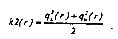
Würde man nur berücksichtigen, daß ein Teil der einfallenden Strahlung wegreflektiert wird und die oben besprochene Verringerung der Energiedichte aufgrund der Vergrößerung der effektiven Fläche Aeff gegenüber der ursprünglichen Fläche A0 beiseite lassen, so ergäbe sich eine wirksame Strahlenergiedichte von (1 - k2(r)) x F gegenüber der einfallenden Strahlenergiedichte F und somit eine Abschwächung der Ablationstiefe d auf kor2(r) x d, wobei 
In
Natürlich sollten die beiden besprochenen Phänomene der Vergrößerung der effektiven Fläche des Laserstrahlspots und der Reflektion miteinander kombiniert betrachtet werden:Of course, the two discussed phenomena of increasing the effective area of the laser beam spot and the reflection should be considered combined:
Von der einfallenden Strahlenergiedichte F trifft eine Strahlenergiedichte F/k1(r) auf der Hornhautoberfläche auf, und davon wird der Anteil (1 - k2(r)) x F/k1(r) nicht wegreflektiert.From the incident beam density F, a beam energy density F / k1 (r) impinges on the corneal surface, and the proportion (1-k2 (r)) x F / k1 (r) thereof is not reflected off.
Somit ergibt sich ein kombinierter Korrekturfaktor kor(r) für die Ablationstiefe zu: 
Der Verlauf dieses kombinierten Korrekturfaktors kor(r) ist in
Wie in
Dies kann man auch anhand von
Mit der Näherung, daß der Laserstrahlspot parallel zur z-Achse eingestrahlt wird, können bereits zufriedenstellende Ergebnisse erzielt werden. Wird der Laserstrahl mittels des Steuerprogramms im Rechner 48 so gesteuert, daß die Verringerung der Ablationstiefe am Rand der Hornhaut ausgeglichen wird, können befriedigendere Heilergebnisse bei der Patientenbehandlung erzielt werden.With the approximation that the laser beam spot is irradiated parallel to the z-axis, already satisfactory results can be achieved. If the laser beam is controlled by the control program in the
Bei einem realen System ist jedoch eher die in
Zur Berechnung dieser Ablationstiefe muß man nur das Koordinatensystem so drehen, daß die z-Achse wieder parallel zum Laserstrahl verläuft. Dann können die oben angegebenen Formeln wieder angewendet werden.To calculate this Ablationstiefe one must only rotate the coordinate system so that the z-axis again runs parallel to the laser beam. Then the formulas given above can be reapplied.
Die Abhängigkeit des Korrekturfaktors kor(r) von dem Versetzungsabstand rv ist für die in
Ein perfektes System berücksichtigt somit nicht nur die Vergrößerung der effektiven Fläche des Laserstrahlspots und die Reflektion an der Hornhautoberfläche, sondern auch den Einfluß der Versetzung. Dies läßt sich darin zusammenfassen, daß der Einfluß des Winkels zwischen Laserstrahl und Hornhautoberfläche berücksichtigt wird.A perfect system thus not only takes into account the increase in the effective area of the laser beam spot and the reflection on the corneal surface, but also the influence of dislocation. This can be summarized in that the influence of the angle between the laser beam and corneal surface is taken into account.
Nicht immer ist dieser Winkel jedoch genau bekannt. Die Erfindung kann daher noch verfeinert werden.However, this angle is not always well known. The invention can therefore be refined.
Erstens ist die Näherung, daß die Hornhaut sphärisch ist, im allgemeinen nicht zutreffend. Sie ist im allgemeinen asphärisch und hat auch oft einen Astigmatismus. Die Hornhaut hat somit an verschiedenen Stellen unterschiedliche Krümmungsradien. Man kann diese Krümmungsradien mit sogenannten Topographie-Systemen vermessen. Mit dieser Information über den lokalen Krümmungsradius kann nun einerseits der Winkel zwischen Laserstrahl und Hornhautoberfläche berechnet werden, wobei man Formel (8) verwendet. Damit kann man den Anteil der auf die Hornhautoberfläche auftretenden Laserstrahlenergie, der wegreflektiert wird, aus den Formeln (6) und (7) ableiten. Zur Berechnung des Einflusses des Winkels zwischen Laserstrahl und Hornhautoberfläche auf die Energiedichte des auf die Hornhautoberfläche auftreffenden Laserstrahlspots können weiterhin die Formeln (2) und (3) verwendet werden, wobei R nun der lokale Krümmungsradius der Hornhaut ist.First, the approximation that the cornea is spherical is generally inaccurate. It is generally aspherical and often has astigmatism. The cornea thus has different radii of curvature at different locations. You can measure these radii of curvature with so-called topography systems. With this information about the local radius of curvature, on the one hand, the angle between the laser beam and the surface of the cornea can be calculated, using formula (8). Thus one can derive the proportion of the laser beam energy occurring on the corneal surface, which is reflected off, from the formulas (6) and (7). To calculate the influence of the angle between the laser beam and the corneal surface on the energy density of the laser beam spot impinging on the corneal surface, the formulas (2) and (3) can still be used, where R is now the local radius of curvature of the cornea.
Zur weiteren Verfeinerung sollte berücksichtigt werden, daß sich der Winkel zwischen Laserstrahl und Hornhautoberfläche auch während des Ablatierens ändert. Wäre beispielsweise nach bisheriger Berechnung eine Folge von 50 Laserstrahlspotpulsen notwendig, um an einer bestimmten Stelle der Hornhaut gemäß dem Ablationsprofil zu ablatieren, so kann es sein, daß sich der Winkel zwischen Laserstrahl und der Hornhautoberfläche nach jedem Puls und somit jeder Teilabtragung weiter derart ändert, daß beispielsweise ein geringerer Anteil des Laserstrahls wegreflektiert wird, so daß anstelle von 50 Pulsen nur 49 oder 48 Pulsen notwendig sind, oder es kann umgekehrt sein, daß während des Ablatierens die Bedingungen ungünstiger werden, so daß anstelle der ursprünglich berechneten 50 Pulse mehr Pulse notwendig sind. Da nach den bisher angegebenen Formeln bekannt ist, um wieviel ein Laserstrahlpuls die Hornhaut ablatiert, kann dieser Effekt bei einer verfeinerten Rechnung bereits im vorhinein berücksichtigt werden. Für diese Berechnung kann die Hornhautoberfläche im Computer simuliert werden, oder es können die sich ändernden lokalen Krümmungsradien der Hornhaut näherungsweise berechnet werden. Dann würde die Berechnung genauso durchgeführt werden wie im im letzten Absatz diskutierten Falle, daß man lokal verschiedene Krümmungsradien einbezieht.For further refinement, it should be taken into account that the angle between laser beam and corneal surface also changes during ablation. For example, if, according to the previous calculation, a sequence of 50 laser beam spot pulses would be necessary to ablate at a certain point of the cornea according to the ablation profile, the angle between the laser beam and the corneal surface may continue to change after each pulse and thus each partial ablation, that, for example, a smaller proportion of the laser beam is reflected away, so that instead of 50 pulses only 49 or 48 pulses are necessary, or conversely, during ablation, the conditions become unfavorable, so that instead of the originally calculated 50 pulses more pulses necessary are. Since, according to the formulas given so far, it is known how much a laser beam pulse ablates the cornea, this effect can already be taken into account in advance with a more refined calculation. For this calculation, the corneal surface can be simulated in the computer, or the changing local radii of curvature of the cornea can be approximated. Then the calculation would be carried out in the same way as in the case discussed in the last paragraph, that locally different radii of curvature are included.
Wie oben bei der Beschreibung von
Die vorliegende Erfindung wurde unter Bezug auf ein System mit Fleck-Abtasten beschrieben, sie ist aber auch bei der Vollabtragung anwendbar wie auch bei der Abtragung mit Scanning-Slit (Schlitzabtragung).The present invention has been described with reference to a stain-sensing system, but it is also applicable to solid ablation as well as scanning-slit ablation.
Für die verwendeten Formeln können numerisch übliche Näherungen benutzt werden.Numerically common approximations can be used for the formulas used.
Claims (1)
- A device for guiding a laser beam, controlled with respect to position and time, over a cornea to be corrected, comprising a laser radiation source (30), means (32) for directing the laser beam onto the eye (19) and a computer (48) for controlling the laser radiation source (30) and the means (32) for directing the laser beam (34), the computer (48) being programmed such that in a control program, according to which the laser beam is guided, the effect of the angle between the laser beam and the corneal surface on the energy density of the laser beam incident on the corneal surface and on the fraction of the radiation reflected by the corneal surface is taken into account,
wherein the fact that the angle between the laser beam and the corneal surface also changes during the ablation is taken into account,
wherein a sequence of laser-beam spot pulses is necessary according to a previous calculation in order to ablate the cornea according to the ablation profile at a particular location, wherein the angle between the laser beam and the corneal surface changes further, after each pulse and therefore each partial ablation, so that less pulses are needed instead of the originally calculated pulses or so that more pulses are needed instead of the pulses originally calculated,
wherein the extent to which a laser-beam pulse ablates the cornea is known, so that the known cornea ablation is taken into account a priori in the calculation, wherein the ablation and the corneal surface are simulated on the computer.
Applications Claiming Priority (3)
| Application Number | Priority Date | Filing Date | Title |
|---|---|---|---|
| DE10022995 | 2000-05-11 | ||
| DE10022995A DE10022995C2 (en) | 2000-05-11 | 2000-05-11 | Device for photorefractive corneal surgery |
| PCT/EP2001/004978 WO2001085075A1 (en) | 2000-05-11 | 2001-05-03 | Method for producing a control program for a device used for performing corneal eye surgery |
Publications (3)
| Publication Number | Publication Date |
|---|---|
| EP1280484A1 EP1280484A1 (en) | 2003-02-05 |
| EP1280484B1 EP1280484B1 (en) | 2007-06-27 |
| EP1280484B2 true EP1280484B2 (en) | 2013-02-27 |
Family
ID=7641595
Family Applications (1)
| Application Number | Title | Priority Date | Filing Date |
|---|---|---|---|
| EP01936314A Expired - Lifetime EP1280484B2 (en) | 2000-05-11 | 2001-05-03 | Device for guiding a laser beam over the cornea of an eye and a method for creating a control program therefore |
Country Status (6)
| Country | Link |
|---|---|
| US (2) | US6887231B2 (en) |
| EP (1) | EP1280484B2 (en) |
| AU (1) | AU6225401A (en) |
| DE (2) | DE10022995C2 (en) |
| ES (1) | ES2287132T5 (en) |
| WO (1) | WO2001085075A1 (en) |
Families Citing this family (46)
| Publication number | Priority date | Publication date | Assignee | Title |
|---|---|---|---|---|
| US6245059B1 (en) * | 1999-04-07 | 2001-06-12 | Visx, Incorporated | Offset ablation profiles for treatment of irregular astigmation |
| JP4067825B2 (en) | 1999-10-21 | 2008-03-26 | テクノラス ゲーエムベーハー オフタルモロギッシェ システム | Iris recognition and tracking for light treatment |
| US7044602B2 (en) | 2002-05-30 | 2006-05-16 | Visx, Incorporated | Methods and systems for tracking a torsional orientation and position of an eye |
| DE10022995C2 (en) * | 2000-05-11 | 2003-11-27 | Wavelight Laser Technologie Ag | Device for photorefractive corneal surgery |
| US7083609B2 (en) | 2002-06-13 | 2006-08-01 | Visx, Incorporated | Corneal topography-based target warping |
| US6786603B2 (en) | 2002-09-25 | 2004-09-07 | Bausch & Lomb Incorporated | Wavefront-generated custom ophthalmic surfaces |
| US7458683B2 (en) | 2003-06-16 | 2008-12-02 | Amo Manufacturing Usa, Llc | Methods and devices for registering optical measurement datasets of an optical system |
| DE10332815B4 (en) * | 2003-07-18 | 2020-10-22 | Carl Zeiss Meditec Ag | Method and apparatus for forming curved cut surfaces in a transparent material |
| DE10334110A1 (en) | 2003-07-25 | 2005-02-17 | Carl Zeiss Meditec Ag | Apparatus and method for forming curved cut surfaces in a transparent material |
| US7481536B2 (en) * | 2004-02-19 | 2009-01-27 | Amo Manufacturing Usa, Llc | Methods and systems for differentiating left and right eye images |
| JP2005341033A (en) * | 2004-05-25 | 2005-12-08 | Konica Minolta Photo Imaging Inc | Imaging apparatus and program |
| US8394084B2 (en) | 2005-01-10 | 2013-03-12 | Optimedica Corporation | Apparatus for patterned plasma-mediated laser trephination of the lens capsule and three dimensional phaco-segmentation |
| ATE516786T1 (en) | 2005-02-15 | 2011-08-15 | Zeiss Carl Meditec Ag | METHOD FOR PRODUCING AN ABLATION PROGRAM, DEPENDING ON THE SHAPE OF A LASER BEAM PROFILE AND ON AN INCLINE OF THE SURFACE TO BE ABLATED; MEANS OF PERFORMING THE PROCEDURES |
| DE102005006897A1 (en) * | 2005-02-15 | 2006-08-24 | Carl Zeiss Meditec Ag | Ablation program establishing method for correcting ametropia of human eye, involves establishing ablation program based on water concentration of surface to be ablated and pre-compensated set-point ablation profile |
| DE102005013558A1 (en) * | 2005-03-23 | 2006-09-28 | Carl Zeiss Meditec Ag | Method and device for increasing the depth of focus of an optical system |
| US8945102B2 (en) * | 2005-07-29 | 2015-02-03 | Alcon Refractivehorizons, Inc. | Laser corneal flap cutting system and associated methods |
| WO2007020105A1 (en) | 2005-08-19 | 2007-02-22 | Wavelight Ag | Method for determining control information for photorefractive cornea surgery and method for preparing necessary correction information |
| ES2389957T3 (en) * | 2006-03-15 | 2012-11-05 | Wavelight Gmbh | Control program for ophthalmologic surgery |
| US10729585B2 (en) | 2006-07-19 | 2020-08-04 | Alcon Inc. | Computer program for ophthalmological surgery |
| US8053191B2 (en) | 2006-08-31 | 2011-11-08 | Westend Asset Clearinghouse Company, Llc | Iterative nucleic acid assembly using activation of vector-encoded traits |
| US8685006B2 (en) * | 2006-11-10 | 2014-04-01 | Carl Zeiss Meditec Ag | Treatment apparatus for surgical correction of defective eyesight, method of generating control data therefore, and method for surgical correction of defective eyesight |
| US8216214B2 (en) * | 2007-03-12 | 2012-07-10 | Ethicon Endo-Surgery, Inc. | Power modulation of a scanning beam for imaging, therapy, and/or diagnosis |
| US8294062B2 (en) * | 2007-08-20 | 2012-10-23 | Universal Laser Systems, Inc. | Laser beam positioning systems for material processing and methods for using such systems |
| DE102007053283B4 (en) | 2007-11-08 | 2019-08-29 | Carl Zeiss Meditec Ag | Treatment device for operative vision correction of an eye and method for generating control data therefor |
| DE102007063962B4 (en) * | 2007-11-08 | 2025-10-30 | Carl Zeiss Meditec Ag | Treatment device for the surgical correction of refractive errors in an eye and method for generating control data for it |
| US8718743B2 (en) * | 2008-04-24 | 2014-05-06 | Duke University | Methods for single-pass volumetric bidirectional blood flow imaging spectral domain optical coherence tomography using a modified hilbert transform |
| US8133127B1 (en) * | 2008-07-21 | 2012-03-13 | Synder Terrance W | Sports training device and methods of use |
| DE102008046834A1 (en) * | 2008-09-11 | 2010-03-18 | Iroc Ag | Control program for controlling electromagnetic radiation for cross-linking of eye tissue |
| US8693745B2 (en) * | 2009-05-04 | 2014-04-08 | Duke University | Methods and computer program products for quantitative three-dimensional image correction and clinical parameter computation in optical coherence tomography |
| DE102009030464B4 (en) | 2009-06-23 | 2022-04-14 | Carl Zeiss Meditec Ag | Laser device and method, in particular operating method for a laser device, for creating irradiation control data for a pulsed laser |
| US8571077B2 (en) | 2010-08-31 | 2013-10-29 | First Solar, Inc. | System and method for laser modulation |
| WO2012078312A2 (en) | 2010-11-12 | 2012-06-14 | Gen9, Inc. | Methods and devices for nucleic acids synthesis |
| US10457935B2 (en) | 2010-11-12 | 2019-10-29 | Gen9, Inc. | Protein arrays and methods of using and making the same |
| WO2012100213A2 (en) | 2011-01-21 | 2012-07-26 | Duke University | Systems and methods for complex conjugate artifact resolved optical coherence tomography |
| US8978660B2 (en) | 2011-07-21 | 2015-03-17 | Amo Development, Llc | Tilt compensation, measurement, and associated adjustment of refractive prescriptions during surgical and other treatments of the eye |
| EP2748318B1 (en) | 2011-08-26 | 2015-11-04 | Gen9, Inc. | Compositions and methods for high fidelity assembly of nucleic acids |
| DE102011085046A1 (en) | 2011-10-21 | 2013-04-25 | Carl Zeiss Meditec Ag | Generation of cut surfaces in a transparent material by means of optical radiation |
| DE102011085047A1 (en) | 2011-10-21 | 2013-04-25 | Carl Zeiss Meditec Ag | Producing cuts in a transparent material by means of optical radiation |
| US9150853B2 (en) | 2012-03-21 | 2015-10-06 | Gen9, Inc. | Methods for screening proteins using DNA encoded chemical libraries as templates for enzyme catalysis |
| CN104603286B (en) | 2012-04-24 | 2020-07-31 | Gen9股份有限公司 | Method for sorting nucleic acids and multiplex preparations in vitro cloning |
| US10744034B2 (en) * | 2012-04-25 | 2020-08-18 | Gregg S. Homer | Method for laser treatment for glaucoma |
| CN104685116A (en) | 2012-06-25 | 2015-06-03 | Gen9股份有限公司 | Methods for nucleic acid assembly and high throughput sequencing |
| US10314745B2 (en) * | 2012-11-30 | 2019-06-11 | Amo Development, Llc | Automatic centration of a surgical pattern on the apex of a curved patient interface |
| EP4420643A3 (en) | 2014-09-09 | 2024-11-13 | AMO Development, LLC | System for synchronized three-dimensional laser incisions |
| DE102023103285A1 (en) | 2023-02-10 | 2024-08-14 | Schwind Eye-Tech-Solutions Gmbh | METHOD FOR PROVIDING CONTROL DATA FOR AN OPHTHALMOLOGICAL LASER OF A TREATMENT DEVICE |
| CN118217006B (en) * | 2024-04-03 | 2024-09-17 | 武汉长江激光科技有限公司 | Laser-based surgical reference scheme generation method and device |
Citations (5)
| Publication number | Priority date | Publication date | Assignee | Title |
|---|---|---|---|---|
| US5219344A (en) † | 1988-06-09 | 1993-06-15 | Visx, Incorporated | Methods and apparatus for laser sculpture of the cornea |
| US5425727A (en) † | 1988-04-01 | 1995-06-20 | Koziol; Jeffrey E. | Beam delivery system and method for corneal surgery |
| DE19702335C1 (en) † | 1997-01-23 | 1998-08-27 | Wavelight Laser Technologie Gm | Material processing arrangement with pulsed laser e.g. for eye surgery |
| EP1040797A2 (en) † | 1999-03-31 | 2000-10-04 | Nidek Co., Ltd. | Corneal surgery apparatus |
| WO2001050945A2 (en) † | 2000-01-12 | 2001-07-19 | Lasersight Technologies, Inc. | Laser fluence compensation of a curved surface |
Family Cites Families (12)
| Publication number | Priority date | Publication date | Assignee | Title |
|---|---|---|---|---|
| US5163934A (en) * | 1987-08-05 | 1992-11-17 | Visx, Incorporated | Photorefractive keratectomy |
| US5098426A (en) * | 1989-02-06 | 1992-03-24 | Phoenix Laser Systems, Inc. | Method and apparatus for precision laser surgery |
| US6099522A (en) * | 1989-02-06 | 2000-08-08 | Visx Inc. | Automated laser workstation for high precision surgical and industrial interventions |
| US5740815A (en) * | 1995-06-07 | 1998-04-21 | Alpins; Noel A. | Method for surgically achieving minimum astigmatism measured refractively and topographically |
| DE4232915A1 (en) * | 1992-10-01 | 1994-04-07 | Hohla Kristian | Device for shaping the cornea by removing tissue |
| US5849006A (en) * | 1994-04-25 | 1998-12-15 | Autonomous Technologies Corporation | Laser sculpting method and system |
| US5843070A (en) * | 1996-05-13 | 1998-12-01 | Partech, Inc. | Simulating corneal laser surgery |
| DE19904753C1 (en) | 1999-02-05 | 2000-09-07 | Wavelight Laser Technologie Gm | Device for photorefractive corneal surgery of the eye for correcting high-order visual defects |
| US6245059B1 (en) * | 1999-04-07 | 2001-06-12 | Visx, Incorporated | Offset ablation profiles for treatment of irregular astigmation |
| US6394999B1 (en) * | 2000-03-13 | 2002-05-28 | Memphis Eye & Cataract Associates Ambulatory Surgery Center | Laser eye surgery system using wavefront sensor analysis to control digital micromirror device (DMD) mirror patterns |
| US6673062B2 (en) * | 2000-03-14 | 2004-01-06 | Visx, Inc. | Generating scanning spot locations for laser eye surgery |
| DE10022995C2 (en) * | 2000-05-11 | 2003-11-27 | Wavelight Laser Technologie Ag | Device for photorefractive corneal surgery |
-
2000
- 2000-05-11 DE DE10022995A patent/DE10022995C2/en not_active Expired - Lifetime
-
2001
- 2001-05-03 EP EP01936314A patent/EP1280484B2/en not_active Expired - Lifetime
- 2001-05-03 DE DE50112665T patent/DE50112665D1/en not_active Expired - Lifetime
- 2001-05-03 ES ES01936314T patent/ES2287132T5/en not_active Expired - Lifetime
- 2001-05-03 AU AU62254/01A patent/AU6225401A/en not_active Abandoned
- 2001-05-03 WO PCT/EP2001/004978 patent/WO2001085075A1/en not_active Ceased
- 2001-05-03 US US10/031,107 patent/US6887231B2/en not_active Expired - Lifetime
-
2005
- 2005-04-19 US US11/109,180 patent/US7544194B2/en not_active Expired - Lifetime
Patent Citations (5)
| Publication number | Priority date | Publication date | Assignee | Title |
|---|---|---|---|---|
| US5425727A (en) † | 1988-04-01 | 1995-06-20 | Koziol; Jeffrey E. | Beam delivery system and method for corneal surgery |
| US5219344A (en) † | 1988-06-09 | 1993-06-15 | Visx, Incorporated | Methods and apparatus for laser sculpture of the cornea |
| DE19702335C1 (en) † | 1997-01-23 | 1998-08-27 | Wavelight Laser Technologie Gm | Material processing arrangement with pulsed laser e.g. for eye surgery |
| EP1040797A2 (en) † | 1999-03-31 | 2000-10-04 | Nidek Co., Ltd. | Corneal surgery apparatus |
| WO2001050945A2 (en) † | 2000-01-12 | 2001-07-19 | Lasersight Technologies, Inc. | Laser fluence compensation of a curved surface |
Non-Patent Citations (3)
| Title |
|---|
| "Höhere Mathematik griffbereit", 1972, AKADEMIE VERLAG, pages: 638 - 643 † |
| BERGMANN-SCHÄFER: "Experimentalphysik", vol. 3, 1987, DE GRUYTER, pages: 496 † |
| MAX BORN: "Principles of Optics", vol. 6, 1993, PERGAMON PRESS, pages: 37 - 45 † |
Also Published As
| Publication number | Publication date |
|---|---|
| US7544194B2 (en) | 2009-06-09 |
| US20030105457A1 (en) | 2003-06-05 |
| US6887231B2 (en) | 2005-05-03 |
| ES2287132T3 (en) | 2007-12-16 |
| WO2001085075A1 (en) | 2001-11-15 |
| DE50112665D1 (en) | 2007-08-09 |
| ES2287132T5 (en) | 2013-05-30 |
| AU6225401A (en) | 2001-11-20 |
| EP1280484B1 (en) | 2007-06-27 |
| DE10022995A1 (en) | 2001-11-29 |
| DE10022995C2 (en) | 2003-11-27 |
| US20050187540A1 (en) | 2005-08-25 |
| EP1280484A1 (en) | 2003-02-05 |
Similar Documents
| Publication | Publication Date | Title |
|---|---|---|
| EP1280484B2 (en) | Device for guiding a laser beam over the cornea of an eye and a method for creating a control program therefore | |
| EP1069877B1 (en) | Device for photorefractive cornea surgery in higher-order visual disorders | |
| EP1210042B1 (en) | Device for the photoablation of the cornea with a laser beam | |
| DE3786308T2 (en) | In vitro method and device for modifying the refractive properties of the cornea. | |
| DE60103609T2 (en) | OPTIMIZING THE ABLATION CORRECTION OF AN OPTICAL SYSTEM | |
| DE69932809T2 (en) | System for laser treatment of presbyopia | |
| EP2306948B1 (en) | Device for ophthalmologic, particularly refractive, laser surgery | |
| DE60310367T2 (en) | OPTIMIZING THE ABLATION CORRECTION OF AN OPTICAL SYSTEM | |
| DE69033376T2 (en) | Device for the treatment of collagen | |
| DE69902549T2 (en) | DEVICE AND METHOD FOR MEASURING DEFECTIVES OF A HUMAN EYE | |
| EP2337534B1 (en) | Device, method and control program for ophthalmologic, particularly refractive, laser surgery | |
| DE19950792A1 (en) | Ophthalmic wavefront aberration diagnostic tool, has camera that aids in focusing aerial image from lenslet array, on wavefront sensor | |
| DE10006896A1 (en) | Production of an intraocular or optical contact lens a blank is produced mechanically and the surface profile material is removed by laser beams according to the calculated structure required to correct the vision | |
| DE102019007148A1 (en) | Arrangement for OCT-supported laser vitreolysis | |
| EP1154742B1 (en) | Device used for the photorefractive keratectomy of the eye using a centering method | |
| DE60036808T2 (en) | MOTION DETECTOR FOR OPHTHALMOLOGICAL LASER ABLATION SYSTEMS | |
| EP3023082B1 (en) | Device for protecting eye tissue during laser treatments | |
| DE102020125552A1 (en) | Method for providing control data for an ophthalmic surgical laser of a treatment device | |
| EP4157171B1 (en) | System for laser-based ametropia correction, and method for the alignment thereof | |
| DE102019135609B4 (en) | Method for controlling an ophthalmic surgical laser and treatment device | |
| WO2021239605A1 (en) | Uv-laser-based system for correcting impaired vision, and method for centering same | |
| EP1702595B1 (en) | Apparatus for ophthalmologic laser surgery | |
| DE102020208676A1 (en) | UV laser based system for ametropia correction | |
| DE102007063962B4 (en) | Treatment device for the surgical correction of refractive errors in an eye and method for generating control data for it | |
| DE102023108625A1 (en) | Method for providing control data for an ophthalmological laser of a treatment device for correcting a cornea |
Legal Events
| Date | Code | Title | Description |
|---|---|---|---|
| PUAI | Public reference made under article 153(3) epc to a published international application that has entered the european phase |
Free format text: ORIGINAL CODE: 0009012 |
|
| 17P | Request for examination filed |
Effective date: 20020107 |
|
| AK | Designated contracting states |
Designated state(s): AT BE CH CY DE DK ES FI FR GB GR IE IT LI LU MC NL PT SE TR |
|
| AX | Request for extension of the european patent |
Extension state: AL LT LV MK RO SI |
|
| RBV | Designated contracting states (corrected) |
Designated state(s): DE ES FR IT |
|
| 17Q | First examination report despatched |
Effective date: 20050329 |
|
| GRAP | Despatch of communication of intention to grant a patent |
Free format text: ORIGINAL CODE: EPIDOSNIGR1 |
|
| RTI1 | Title (correction) |
Free format text: DEVICE FOR GUIDING A LASER BEAM OVER THE CORNEA OF AN EYE AND A METHOD FOR CREATING A CONTROL PROGRAM THEREFORE |
|
| GRAS | Grant fee paid |
Free format text: ORIGINAL CODE: EPIDOSNIGR3 |
|
| GRAA | (expected) grant |
Free format text: ORIGINAL CODE: 0009210 |
|
| AK | Designated contracting states |
Kind code of ref document: B1 Designated state(s): DE ES FR IT |
|
| REF | Corresponds to: |
Ref document number: 50112665 Country of ref document: DE Date of ref document: 20070809 Kind code of ref document: P |
|
| ET | Fr: translation filed | ||
| REG | Reference to a national code |
Ref country code: ES Ref legal event code: FG2A Ref document number: 2287132 Country of ref document: ES Kind code of ref document: T3 |
|
| PLBI | Opposition filed |
Free format text: ORIGINAL CODE: 0009260 |
|
| PLAZ | Examination of admissibility of opposition: despatch of communication + time limit |
Free format text: ORIGINAL CODE: EPIDOSNOPE2 |
|
| 26 | Opposition filed |
Opponent name: CARL ZEISS MEDITEC AG Effective date: 20080327 |
|
| PLAX | Notice of opposition and request to file observation + time limit sent |
Free format text: ORIGINAL CODE: EPIDOSNOBS2 |
|
| PLBA | Examination of admissibility of opposition: reply received |
Free format text: ORIGINAL CODE: EPIDOSNOPE4 |
|
| PLAF | Information modified related to communication of a notice of opposition and request to file observations + time limit |
Free format text: ORIGINAL CODE: EPIDOSCOBS2 |
|
| PLBB | Reply of patent proprietor to notice(s) of opposition received |
Free format text: ORIGINAL CODE: EPIDOSNOBS3 |
|
| PLBP | Opposition withdrawn |
Free format text: ORIGINAL CODE: 0009264 |
|
| PUAH | Patent maintained in amended form |
Free format text: ORIGINAL CODE: 0009272 |
|
| STAA | Information on the status of an ep patent application or granted ep patent |
Free format text: STATUS: PATENT MAINTAINED AS AMENDED |
|
| 27A | Patent maintained in amended form |
Effective date: 20130227 |
|
| AK | Designated contracting states |
Kind code of ref document: B2 Designated state(s): DE ES FR IT |
|
| REG | Reference to a national code |
Ref country code: DE Ref legal event code: R102 Ref document number: 50112665 Country of ref document: DE Effective date: 20130227 |
|
| REG | Reference to a national code |
Ref country code: ES Ref legal event code: DC2A Ref document number: 2287132 Country of ref document: ES Kind code of ref document: T5 Effective date: 20130530 |
|
| REG | Reference to a national code |
Ref country code: FR Ref legal event code: PLFP Year of fee payment: 16 |
|
| REG | Reference to a national code |
Ref country code: FR Ref legal event code: PLFP Year of fee payment: 17 |
|
| REG | Reference to a national code |
Ref country code: FR Ref legal event code: PLFP Year of fee payment: 18 |
|
| REG | Reference to a national code |
Ref country code: DE Ref legal event code: R082 Ref document number: 50112665 Country of ref document: DE Representative=s name: WUESTHOFF & WUESTHOFF, PATENTANWAELTE PARTG MB, DE Ref country code: DE Ref legal event code: R081 Ref document number: 50112665 Country of ref document: DE Owner name: ALCON INC., CH Free format text: FORMER OWNER: WAVELIGHT LASER TECHNOLOGIE AG, 91058 ERLANGEN, DE |
|
| PGFP | Annual fee paid to national office [announced via postgrant information from national office to epo] |
Ref country code: ES Payment date: 20200601 Year of fee payment: 20 Ref country code: FR Payment date: 20200505 Year of fee payment: 20 Ref country code: DE Payment date: 20200422 Year of fee payment: 20 |
|
| PGFP | Annual fee paid to national office [announced via postgrant information from national office to epo] |
Ref country code: IT Payment date: 20200428 Year of fee payment: 20 |
|
| REG | Reference to a national code |
Ref country code: DE Ref legal event code: R071 Ref document number: 50112665 Country of ref document: DE |
|
| REG | Reference to a national code |
Ref country code: ES Ref legal event code: FD2A Effective date: 20210826 |
|
| PG25 | Lapsed in a contracting state [announced via postgrant information from national office to epo] |
Ref country code: ES Free format text: LAPSE BECAUSE OF EXPIRATION OF PROTECTION Effective date: 20210504 |