EP1280231A1 - Antenne boucle en forme de diamant pour dispositif d'entrée/sortie sans fil - Google Patents
Antenne boucle en forme de diamant pour dispositif d'entrée/sortie sans fil Download PDFInfo
- Publication number
- EP1280231A1 EP1280231A1 EP01118163A EP01118163A EP1280231A1 EP 1280231 A1 EP1280231 A1 EP 1280231A1 EP 01118163 A EP01118163 A EP 01118163A EP 01118163 A EP01118163 A EP 01118163A EP 1280231 A1 EP1280231 A1 EP 1280231A1
- Authority
- EP
- European Patent Office
- Prior art keywords
- wing
- loop antenna
- diamond
- antenna
- wireless
- Prior art date
- Legal status (The legal status is an assumption and is not a legal conclusion. Google has not performed a legal analysis and makes no representation as to the accuracy of the status listed.)
- Withdrawn
Links
Images

Classifications
-
- H—ELECTRICITY
- H01—ELECTRIC ELEMENTS
- H01Q—ANTENNAS, i.e. RADIO AERIALS
- H01Q7/00—Loop antennas with a substantially uniform current distribution around the loop and having a directional radiation pattern in a plane perpendicular to the plane of the loop
-
- H—ELECTRICITY
- H01—ELECTRIC ELEMENTS
- H01Q—ANTENNAS, i.e. RADIO AERIALS
- H01Q1/00—Details of, or arrangements associated with, antennas
- H01Q1/36—Structural form of radiating elements, e.g. cone, spiral, umbrella; Particular materials used therewith
-
- H—ELECTRICITY
- H01—ELECTRIC ELEMENTS
- H01Q—ANTENNAS, i.e. RADIO AERIALS
- H01Q11/00—Electrically-long antennas having dimensions more than twice the shortest operating wavelength and consisting of conductive active radiating elements
- H01Q11/02—Non-resonant antennas, e.g. travelling-wave antenna
- H01Q11/06—Rhombic antennas; V-antennas
-
- H—ELECTRICITY
- H01—ELECTRIC ELEMENTS
- H01Q—ANTENNAS, i.e. RADIO AERIALS
- H01Q9/00—Electrically-short antennas having dimensions not more than twice the operating wavelength and consisting of conductive active radiating elements
- H01Q9/04—Resonant antennas
- H01Q9/16—Resonant antennas with feed intermediate between the extremities of the antenna, e.g. centre-fed dipole
- H01Q9/26—Resonant antennas with feed intermediate between the extremities of the antenna, e.g. centre-fed dipole with folded element or elements, the folded parts being spaced apart a small fraction of operating wavelength
- H01Q9/265—Open ring dipoles; Circular dipoles
-
- H—ELECTRICITY
- H01—ELECTRIC ELEMENTS
- H01Q—ANTENNAS, i.e. RADIO AERIALS
- H01Q9/00—Electrically-short antennas having dimensions not more than twice the operating wavelength and consisting of conductive active radiating elements
- H01Q9/04—Resonant antennas
- H01Q9/30—Resonant antennas with feed to end of elongated active element, e.g. unipole
- H01Q9/42—Resonant antennas with feed to end of elongated active element, e.g. unipole with folded element, the folded parts being spaced apart a small fraction of the operating wavelength
Definitions
- the present invention generally relates to a loop antenna for a wireless I/O device, and more specifically to a diamond-shaped loop antenna with a side wing on two opposite sides respectively.
- FIG. 1 shows such a typical rectangular-shaped loop antenna 100.
- ISM Industrial, Scientific and Medical
- the primary object of this invention is to provide a loop antenna with a diamond-shaped structure, which under the condition of matching the circuit impedances, the antenna has a high efficiency of radiation, and is less affected by hand.
- this invention proposes a diamond-shaped loop antenna for wireless I/O device, its feature is as follows: on two opposite sides of the loop antenna each has a side wing, which forms an upper-edge-angle with the upper side of the antenna.
- the side wing itself also has a wing-angle, and both the upper-edge-angle and the wing-angle are located on the same plane.
- FIG. 1 shows the block diagram of a typical rectangular-shaped loop antenna.
- FIG. 2 shows the block diagram of an embodiment of the diamond-shaped loop antenna according to this invention.
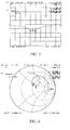
- FIG. 3 shows the experimental result of return loss measured for the embodiment according to this invention.
- FIG. 4 shows the measurement result on the Smith Chart for the embodiment according to this invention.
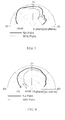
- FIG. 5 shows the result of radiation field type measured for the embodiment according to this invention.
- FIG. 6 shows the result of radiation field type measured for the embodiment according to this invention.
- FIG. 2 shows the block diagram of an embodiment of the diamond-shaped loop antenna according to this invention.
- the diamond-shaped antenna 200 comprising: a microwave element 210 having first side 211, second side 212 and third side 213 formed by a metal wire, said sides being formed in a loop shape, said first side 211 and second side 212 having a side wing 214, 215 respectively; a feedline 220 being located at one end of said first side 211; and an output end 230 being located at one end of said second side 212; wherein said side wing 214 and said third side 213 of the microwave element 210 form an upper-edge-angle ⁇ , and said side wing 214 itself also has a wing-angle ⁇ .
- the upper-edge-angle ⁇ and the wing-angle ⁇ are located on the same plane, wherein the two upper-edge-angles ⁇ both have a degree of 45°, and the two wing-angles ⁇ both have a degree of 90°.
- the antenna is made of copper with diameter of 0.8mm.
- the diamond-shaped antenna 200 has two side wings 214, 215, which result in the upper-edge-angle ⁇ and the wing-angle ⁇ , it reduces the hand effect from antenna radiation characteristics.
- the antenna radiation field type is measured by using the near-field measurement system developed by the Near-field System Inc. (NSI).
- NSSI Near-field System Inc.
- the maximum far-field value obtained for the antenna transmitted power is -53.54dB, but to measure the effect when a hand is located 2cm above the antenna, the maximum far-field value obtained is -57.53dB, thus the hand has an effect of about 4dB for the antenna.
- the diamond-shaped loop antenna 200 is measured as shown in FIG.
- the maximum far-field value obtained is -52.21dB, and when a hand is located 2cm above the antenna, the maximum far-field value obtained is - 55.95dB.
- the hand has an effect of about 3.7dB on the antenna.
- FIG. 4 shows the measurement result on the Smith Chart for the embodiment according to this invention. The chart shows that the same conclusion is obtained in this figure as in FIG. 3.
- FIG. 5 shows the result of radiation field type measured for the embodiment according to this invention.
- the measured E plane (x-z plane) field type is obtained by operating the antenna at 2.45GHz, wherein the thick line represents the experimental result without palm effect and the thin line represents the experimental result with palm effect respectively.
- FIG. 6 shows the result of radiation field type measured for the embodiment according to this invention.
- the measured H plane (y-z plane) field type is obtained by operating the antenna at 2.45GHz, wherein the thick line represents the experimental result without palm effect and the thin line represents the experimental result with palm effect respectively.
- the radiation field type (E-plane: x-z) which is perpendicular to the hand direction (y direction)
- the radiation field type (H-plane: y-z) which is parallel to the hand direction (y direction), is more affected by hand.
- this invention proposes a diamond-shaped loop antenna having a simple design, only needing to change the two opposite sides of the general rectangular-shaped loop antenna into two side wings with diamond-shaped structure. Then the radiation efficiency can be improved, and the hand effect on the antenna characteristics is reduced. Moreover, a typical copper may fabricate the material of the antenna. This achieves an antenna with low cost, high application value, and good efficiency. It has not only accomplished an expecting practical use but also a new design.
Priority Applications (1)
| Application Number | Priority Date | Filing Date | Title |
|---|---|---|---|
| EP01118163A EP1280231A1 (fr) | 2001-07-26 | 2001-07-26 | Antenne boucle en forme de diamant pour dispositif d'entrée/sortie sans fil |
Applications Claiming Priority (1)
| Application Number | Priority Date | Filing Date | Title |
|---|---|---|---|
| EP01118163A EP1280231A1 (fr) | 2001-07-26 | 2001-07-26 | Antenne boucle en forme de diamant pour dispositif d'entrée/sortie sans fil |
Publications (1)
| Publication Number | Publication Date |
|---|---|
| EP1280231A1 true EP1280231A1 (fr) | 2003-01-29 |
Family
ID=8178150
Family Applications (1)
| Application Number | Title | Priority Date | Filing Date |
|---|---|---|---|
| EP01118163A Withdrawn EP1280231A1 (fr) | 2001-07-26 | 2001-07-26 | Antenne boucle en forme de diamant pour dispositif d'entrée/sortie sans fil |
Country Status (1)
| Country | Link |
|---|---|
| EP (1) | EP1280231A1 (fr) |
Cited By (6)
| Publication number | Priority date | Publication date | Assignee | Title |
|---|---|---|---|---|
| EP1601049A1 (fr) * | 2004-05-19 | 2005-11-30 | Delphi Technologies, Inc. | Antenne en boucle à deux bandes |
| US7768400B2 (en) | 2005-06-25 | 2010-08-03 | Omni-Id Limited | Electromagnetic radiation decoupler |
| US7880619B2 (en) | 2006-06-16 | 2011-02-01 | Omni-Id Limited | Electromagnetic enhancement and decoupling |
| US8453936B2 (en) | 2006-12-14 | 2013-06-04 | Omni-Id Cayman Limited | Switchable radiation enhancement and decoupling |
| US8636223B2 (en) | 2008-08-20 | 2014-01-28 | Omni-Id Cayman Limited | One and two-part printable EM tags |
| US8684270B2 (en) | 2006-12-20 | 2014-04-01 | Omni-Id Cayman Limited | Radiation enhancement and decoupling |
Citations (3)
| Publication number | Priority date | Publication date | Assignee | Title |
|---|---|---|---|---|
| GB692692A (en) * | 1947-12-24 | 1953-06-10 | Charles Alexander Vivian Heath | Improvements in and relating to radio aerials |
| US5767813A (en) * | 1993-05-27 | 1998-06-16 | Raytheon Ti Systems, Inc. | Efficient electrically small loop antenna with a planar base element |
| WO2001063697A1 (fr) * | 2000-02-26 | 2001-08-30 | Anthony Rabie | Antenne |
-
2001
- 2001-07-26 EP EP01118163A patent/EP1280231A1/fr not_active Withdrawn
Patent Citations (3)
| Publication number | Priority date | Publication date | Assignee | Title |
|---|---|---|---|---|
| GB692692A (en) * | 1947-12-24 | 1953-06-10 | Charles Alexander Vivian Heath | Improvements in and relating to radio aerials |
| US5767813A (en) * | 1993-05-27 | 1998-06-16 | Raytheon Ti Systems, Inc. | Efficient electrically small loop antenna with a planar base element |
| WO2001063697A1 (fr) * | 2000-02-26 | 2001-08-30 | Anthony Rabie | Antenne |
Non-Patent Citations (1)
| Title |
|---|
| WONHA CHOE ET AL: "ANALYSIS OF HIGHER ORDER REGULAR POLYGONAL LOOP ANTENNAS", IEEE TRANSACTIONS ON ANTENNAS AND PROPAGATION, IEEE INC. NEW YORK, US, vol. 38, no. 7, 1 July 1990 (1990-07-01), pages 1114 - 1117, XP000137535, ISSN: 0018-926X * |
Cited By (13)
| Publication number | Priority date | Publication date | Assignee | Title |
|---|---|---|---|---|
| US7710335B2 (en) | 2004-05-19 | 2010-05-04 | Delphi Technologies, Inc. | Dual band loop antenna |
| EP1601049A1 (fr) * | 2004-05-19 | 2005-11-30 | Delphi Technologies, Inc. | Antenne en boucle à deux bandes |
| US9104952B2 (en) | 2005-06-25 | 2015-08-11 | Omni-Id Cayman Limited | Electromagnetic radiation decoupler |
| US7768400B2 (en) | 2005-06-25 | 2010-08-03 | Omni-Id Limited | Electromagnetic radiation decoupler |
| US8299927B2 (en) | 2005-06-25 | 2012-10-30 | Omni-Id Cayman Limited | Electromagnetic radiation decoupler |
| US9646241B2 (en) | 2005-06-25 | 2017-05-09 | Omni-Id Cayman Limited | Electromagnetic radiation decoupler |
| US7880619B2 (en) | 2006-06-16 | 2011-02-01 | Omni-Id Limited | Electromagnetic enhancement and decoupling |
| US8264358B2 (en) | 2006-06-16 | 2012-09-11 | Omni-Id Cayman Limited | Electromagnetic enhancement and decoupling |
| US8502678B2 (en) | 2006-06-16 | 2013-08-06 | Omni-Id Cayman Limited | Electromagnetic enhancement and decoupling |
| US8453936B2 (en) | 2006-12-14 | 2013-06-04 | Omni-Id Cayman Limited | Switchable radiation enhancement and decoupling |
| US8684270B2 (en) | 2006-12-20 | 2014-04-01 | Omni-Id Cayman Limited | Radiation enhancement and decoupling |
| US8794533B2 (en) | 2008-08-20 | 2014-08-05 | Omni-Id Cayman Limited | One and two-part printable EM tags |
| US8636223B2 (en) | 2008-08-20 | 2014-01-28 | Omni-Id Cayman Limited | One and two-part printable EM tags |
Similar Documents
| Publication | Publication Date | Title |
|---|---|---|
| CA2200675C (fr) | Structure d'antenne a circuits imprimes utilisee pour la transmission de donnees sans fil | |
| EP1753080B1 (fr) | Antenne cadre a bande ultra large | |
| Salonen et al. | A small planar inverted-F antenna for wearable applications | |
| TW384554B (en) | Increased bandwidth patch antenna | |
| TW200950213A (en) | Ultra high frequency planar antenna | |
| US20100295750A1 (en) | Antenna for diversity applications | |
| JP2005086536A (ja) | プリントアンテナ | |
| TW200807814A (en) | Dual band flat antenna | |
| TWM281306U (en) | Broadband antenna and electronic device having broadband antenna | |
| EP1026779A3 (fr) | Agencement d'antenne hybride utilisé pour des systèmes d'identifications électroniques | |
| Kashiwa et al. | Analysis of microstrip antennas on a curved surface using the conformal grids FD-TD method | |
| EP1280231A1 (fr) | Antenne boucle en forme de diamant pour dispositif d'entrée/sortie sans fil | |
| Rahman et al. | The broken-heart printed antenna for ultrawideband applications: Design and characteristics analysis | |
| Wahyudi et al. | Broadband planar bow-tie antenna on high resistivity silicon substrate for terahertz application | |
| Ghosh et al. | Loaded wire antenna as EMI sensor | |
| Kuo et al. | Analysis of a 900/1800-MHz dual-band gap loop antenna on a handset with proximate head and hand model | |
| Wang | A compact antenna design for UHF RFID applications | |
| Klemm et al. | Characterisation of an aperture-stacked patch antenna for ultra-wideband wearable radio systems | |
| Sun et al. | A compact printed end-fire antenna for radio frequency identification (RFID) handheld reader | |
| Song et al. | A conformal conical archimedean spiral antenna for UWB communications | |
| Liu et al. | Spherical‐coordinate FDTD analysis of conical antennas mounted above finite ground planes | |
| TW201114111A (en) | Single band antenna | |
| Liu et al. | An Inductive Self-Complementary Hilbert-Curve Antenn for UHF RFID Broadband and Circular Polarization Tags | |
| CN215579053U (zh) | 双频天线 | |
| Hsu et al. | Application of quasi log-periodic antenna for UHF passive RFID tag design featuring constant power transmission coefficient over broadband operation |
Legal Events
| Date | Code | Title | Description |
|---|---|---|---|
| PUAI | Public reference made under article 153(3) epc to a published international application that has entered the european phase |
Free format text: ORIGINAL CODE: 0009012 |
|
| AK | Designated contracting states |
Designated state(s): AT BE CH CY DE DK ES FI FR GB GR IE IT LI LU MC NL PT SE TR |
|
| AX | Request for extension of the european patent |
Extension state: AL LT LV MK RO SI |
|
| AKX | Designation fees paid |
Designated state(s): DE ES FR GB IT |
|
| STAA | Information on the status of an ep patent application or granted ep patent |
Free format text: STATUS: THE APPLICATION IS DEEMED TO BE WITHDRAWN |
|
| 18D | Application deemed to be withdrawn |
Effective date: 20030730 |