EP1280093A2 - System and method for improved object identification - Google Patents
System and method for improved object identification Download PDFInfo
- Publication number
- EP1280093A2 EP1280093A2 EP02255126A EP02255126A EP1280093A2 EP 1280093 A2 EP1280093 A2 EP 1280093A2 EP 02255126 A EP02255126 A EP 02255126A EP 02255126 A EP02255126 A EP 02255126A EP 1280093 A2 EP1280093 A2 EP 1280093A2
- Authority
- EP
- European Patent Office
- Prior art keywords
- objects
- interest
- region
- frequency
- energy
- Prior art date
- Legal status (The legal status is an assumption and is not a legal conclusion. Google has not performed a legal analysis and makes no representation as to the accuracy of the status listed.)
- Withdrawn
Links
Images


Classifications
-
- G—PHYSICS
- G01—MEASURING; TESTING
- G01S—RADIO DIRECTION-FINDING; RADIO NAVIGATION; DETERMINING DISTANCE OR VELOCITY BY USE OF RADIO WAVES; LOCATING OR PRESENCE-DETECTING BY USE OF THE REFLECTION OR RERADIATION OF RADIO WAVES; ANALOGOUS ARRANGEMENTS USING OTHER WAVES
- G01S13/00—Systems using the reflection or reradiation of radio waves, e.g. radar systems; Analogous systems using reflection or reradiation of waves whose nature or wavelength is irrelevant or unspecified
- G01S13/02—Systems using reflection of radio waves, e.g. primary radar systems; Analogous systems
- G01S13/0209—Systems with very large relative bandwidth, i.e. larger than 10 %, e.g. baseband, pulse, carrier-free, ultrawideband
-
- G—PHYSICS
- G01—MEASURING; TESTING
- G01S—RADIO DIRECTION-FINDING; RADIO NAVIGATION; DETERMINING DISTANCE OR VELOCITY BY USE OF RADIO WAVES; LOCATING OR PRESENCE-DETECTING BY USE OF THE REFLECTION OR RERADIATION OF RADIO WAVES; ANALOGOUS ARRANGEMENTS USING OTHER WAVES
- G01S13/00—Systems using the reflection or reradiation of radio waves, e.g. radar systems; Analogous systems using reflection or reradiation of waves whose nature or wavelength is irrelevant or unspecified
- G01S13/02—Systems using reflection of radio waves, e.g. primary radar systems; Analogous systems
- G01S13/04—Systems determining presence of a target
-
- G—PHYSICS
- G01—MEASURING; TESTING
- G01S—RADIO DIRECTION-FINDING; RADIO NAVIGATION; DETERMINING DISTANCE OR VELOCITY BY USE OF RADIO WAVES; LOCATING OR PRESENCE-DETECTING BY USE OF THE REFLECTION OR RERADIATION OF RADIO WAVES; ANALOGOUS ARRANGEMENTS USING OTHER WAVES
- G01S13/00—Systems using the reflection or reradiation of radio waves, e.g. radar systems; Analogous systems using reflection or reradiation of waves whose nature or wavelength is irrelevant or unspecified
- G01S13/74—Systems using reradiation of radio waves, e.g. secondary radar systems; Analogous systems
- G01S13/75—Systems using reradiation of radio waves, e.g. secondary radar systems; Analogous systems using transponders powered from received waves, e.g. using passive transponders, or using passive reflectors
- G01S13/751—Systems using reradiation of radio waves, e.g. secondary radar systems; Analogous systems using transponders powered from received waves, e.g. using passive transponders, or using passive reflectors wherein the responder or reflector radiates a coded signal
- G01S13/753—Systems using reradiation of radio waves, e.g. secondary radar systems; Analogous systems using transponders powered from received waves, e.g. using passive transponders, or using passive reflectors wherein the responder or reflector radiates a coded signal using frequency selective elements, e.g. resonator
-
- G—PHYSICS
- G01—MEASURING; TESTING
- G01S—RADIO DIRECTION-FINDING; RADIO NAVIGATION; DETERMINING DISTANCE OR VELOCITY BY USE OF RADIO WAVES; LOCATING OR PRESENCE-DETECTING BY USE OF THE REFLECTION OR RERADIATION OF RADIO WAVES; ANALOGOUS ARRANGEMENTS USING OTHER WAVES
- G01S13/00—Systems using the reflection or reradiation of radio waves, e.g. radar systems; Analogous systems using reflection or reradiation of waves whose nature or wavelength is irrelevant or unspecified
- G01S13/88—Radar or analogous systems specially adapted for specific applications
Definitions
- the present invention relates in general to a method for identifying objects within a set of objects and to a system for doing the same.
- One approach to providing the desired object identification is to attach bar codes to each of the objects and to subsequently read these bar codes when an object presence/absence determination is sought. Since bar codes are generally read by a reader placed in substantial proximity to a bar code imprint or sticker, a mechanism for moving a bar code reader into a suitable reading position is generally needed. For example, in a tape library container, where individual tape cartridges are affixed with bar codes for later identification, a robot arm may be employed to move a bar code reader into position to read bar codes disposed on individual tape cartridges.
- Another approach to providing object presence/absence detection is to equip objects, whose presence information is sought, with a computer chip able to intelligently communicate with an appropriately located controller or computer.
- This approach would generally provide each equipped object with the ability to intelligently transmit and receive a broad range of information over a connection to a central controller. While this approach would provide a central controller with the ability to perform object presence detection, this solution generally represents an unnecessarily elaborate, complicated, and expensive approach to a relatively simple communication function.
- the present invention is directed to a method for identifying objects within a set of objects, the method comprising the steps of transmitting a signal toward a region of interest, receiving energy reflected from said region of interest, establishing a baseline field strength for said received reflected energy, determining at least one frequency at which said field strength substantially differs from said baseline field strength for said received reflected energy, and identifying at least one object within said region of interest based upon said determined at least one frequency.
- the present invention is also directed to a system for detecting objects within at least one region of interest, wherein the system preferably comprises object detection equipment disposed conveniently to a region of interest, a set of objects for detection by the object detection equipment, and at least one antenna disposed on each object for uniquely identifying this antenna-equipped object to the object detection equipment.
- the system preferably comprises object detection equipment disposed conveniently to a region of interest, a set of objects for detection by the object detection equipment, and at least one antenna disposed on each object for uniquely identifying this antenna-equipped object to the object detection equipment.
- the present invention is also directed to a system for detecting object presence, the system comprising means for transmitting RF (radio frequency) energy towards objects in a region of interest, means for receiving RF energy from said objects in said region of interest, means for generating at least one resonant frequency to represent an object population in said region of interest, means for altering said received RF energy with said generated at least one resonant frequency, and means for analyzing said altered received RF energy.
- RF radio frequency
- the present invention is directed to a system and method which employs a wireless communication mechanism to identify objects present within a region of interest.
- a radio frequency (RF) signal is transmitted from a selected location in proximity to a region of interest, such as a container or tape library, and impinges upon strips of material disposed on each of the objects located within the region of interest.
- the material strips are preferably sized so as to cause the strips to have distinctive resonant frequencies, thereby providing a mechanism for uniquely identifying the objects within a region of interest based upon reflected energy received at an appropriately located receiver.
- the field strength of a frequency at a receiver may be either increased or decreased by the presence of an antenna.
- the inventive mechanism preferably detects lower or higher than expected field strengths for one or more frequencies within a frequency spectrum under examination.
- Existing in-store theft protection systems have employed transmitters and receivers to trigger an alarm upon detecting an attempted unauthorized removal of an item from a secured area. Such systems typically employ a transmitter, a receiver suitably matched to the receiver, and resonant antennae appropriately deployed on objects to be protected from theft or other unauthorized movement. However, since all protected items are detected by employing the same detection frequency, there is no reason to deploy antennae having different dimensions and thereby different resonant frequencies.
- Store theft protection systems generally operate to determine whether any protected item is being impermissibly moved past a particular checkpoint. Distinguishing between different protected items is neither necessary nor beneficial because the same warning condition should logically be triggered whenever any such protected item is being impermissibly moved. Thus, uniquely identifying the protected items provides no benefit to a theft protection system. Thus, such theft protection systems therefore do not provide any motivation to employ antennae having varying resonant frequencies on different items within a secured area.
- the inventive mechanism provides a rapid and simple method for identifying a population of objects present within a region of interest.
- object presence detection may be practiced without a need for complex mechanical equipment to position data acquisition devices or to be disposed on each object to be identified.
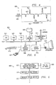
- FIGURE 1A is a perspective view of a tape cartridge 100 having a resonant antenna according to a preferred embodiment of the present invention.
- FIGURE 1B is an enlarged perspective view of a portion of the tape cartridge depicted in FIGURE 1A.
- label 101 is affixed to tape cartridge (or other object) 100 to which an antenna 151 may in turn be readily attached.
- Antenna 151 may be a printed area of conducting ink, a metal antenna, or metal strip in any one of a number of configurations. Regardless of the configuration of antenna 151, its dimensions are preferably strategically selected and accurately implemented so as to ensure that each antenna resonates at its own pre-selected frequency.
- the various antennae 151 are preferably dimensioned, or otherwise uniquely configured, so as to all resonate at different frequencies. In this manner, all objects within a particular inventory system are preferably uniquely identifiable.
- each antenna 151 is established so as to resonate at a pre-selected frequency.
- other dimensions and/or characteristics of a set of antennae may be varied so that no two of the antennae within the pertinent set of antennae have the same resonant frequency.
- One additional desirable design constraint is to avoid having any one antenna resonate at a frequency which is a harmonic of any other antenna's resonant frequency. A harmonic of this sort could cause a computer interpreting incoming data to misinterpret a harmonic of one antenna to be the resonant frequency associated with another antenna.
- various standard means may be employed to manufacture the antennae.
- printers may be modified to use conductive ink in place of standard ink.
- the inventive mechanism is preferably able to provide both a total count of objects within a region of interest as well as a specific identification of each particular object.
- the instant discussion is primarily directed toward the identification of objects of the same type but with unique identification, the present invention is applicable to the identification of objects of varying type stored within a single region of interest, such as for instance, a tape cartridge and a compact disk container stored within a common storage unit.
- FIGURE 2 is a perspective view of a container 200 suitable for holding a plurality of tape cartridges 100 according to a preferred embodiment of the present invention.
- container 200 is preferably a metal cabinet or tape library for storage of such tape cartridges.
- a series of tape cartridges 100 is shown disposed within container 200.
- the inventive object presence detection mechanism does not limit the available geometric configurations of object storage arrangements within container 200. Accordingly, a plurality of rows and/or columns may be employed.
- a plurality of arrays of objects may be stored within container 200, displaced from one another along the "depth" dimension 205 of container 200.
- Such configurations are enabled by the present invention because the object identification communication mechanism of the present invention does not require that objects be located in a manner so as to be accessible by a bar code reader.
- container 200 is made of metal and thereby operates to insulate its own interior from extraneous frequencies which could disrupt the proper interpretation of RF energy reflected back to receivers 202-204.
- the interior of container 200 operates as the relevant region of interest within which a system according to the present invention conducts object presence detection.
- Tx (transmitter) 201 transmits RF signal energy throughout container 200.
- Receivers (Rx) 202-204 are preferably placed in various locations within container 200 to receive RF energy reflected from objects, which may be tape cartridges 100, disposed within container 200. Although three receivers 202-204 are shown in FIGURE 2, it will be appreciated that fewer or more than three receivers may be employed. Likewise, although only one transmitter is shown in FIGURE 2, it will be appreciated that any number of transmitters could be deployed. Moreover, the transmitters and receivers could either be separate entities, as shown in FIGURE 2, or combined into transceivers. In yet another alternative embodiment, a combination of receivers, transmitters, and transceivers may be employed, and all such variations are included within the scope of the present invention.
- a region of interest generally corresponds to a region for which object presence information is sought and object presence detection conducted. Other than when objects have been destroyed, it follows that all objects ever labeled and associated with a particular frequency are present somewhere.
- the role of the inventive object presence detection mechanism is preferably to determine object presence detection within a particular region, known herein as the "region of interest.”
- the interior of container 200 is one example of such a region of interest.
- numerous alternative configurations of such a region of interest could be employed, and all such variations are included within the scope of the present invention.
- a region of interest need not necessarily have defined physical boundaries such as those included within preferably metal container 200.
- a transmitter could beneficially check to see whether a selected group of such drill bits is present in a work area in proximity to a particular drill or other tool. This work area need not necessarily be bounded by metal or other mechanical barriers.
- Such a drill bit detection mechanism could simply operate to detect whether particular tools are within the RF transmission and reception ranges of the transmitters and receivers, respectively, employed in that particular object detection scheme.
- an inventorying system generally includes at least one region of interest and one full set of objects wherein each object is assigned a unique frequency and fitted with an antenna resonant at this assigned frequency for detection thereof by appropriate frequency analysis equipment.
- each region of interest is equipped with at least one transmitter for emitting RF signal energy and at least one receiver for receiving RF energy which is preferably modified by the presence of resonant antennae disposed within that receiver's region of interest.
- a plurality of regions of interest, each having associated transmitters, receivers, analyzing circuitry, and data processing equipment may be employed in connection with a single inventory system which employs a uniform association of resonant frequencies with specific objects or components.
- a plurality of different regions of interest 300, 602 forming part of a single inventory system 600 could operate substantially independently of one another while still employing a common source of data associating resonant frequencies with specific objects 601.
- duplicate and/or ambiguous identification of object presence may be avoided, and object presence detection data from different inventory system segments may optionally be combined in order to present comprehensive object location data for entire inventory system.
- Full set of objects 603 generally corresponds to all objects recognizable to inventory system 600 and associated with identifying frequencies in data table 601.
- FIGURE 3 is a block diagram of an inventory system segment according to a preferred embodiment of the present invention.
- Tx 201 transmits RF signal energy 303 toward objects disposed within region of interest 302.
- the frequency spectra of energy reflected 304 from objects within region of interest 302 preferably reflect the presence of carefully tuned antennae affixed to objects within region of interest 302.
- region of interest 302 may contain all objects recognizable to analyzing circuitry 301, or a subset of this set of objects.
- analyzing circuitry 301 is employed to process reflected RF signal energy 304 and to identify specific frequencies at which resonance occurs within region of interest 302 and thereby determine which objects are present within region of interest 302.
- field strength 401 of a received reflected RF signal energy is plotted against frequency 402.
- peaks and/or troughs in the field strength occur at frequencies at which a resonant frequency interacted with a transmission frequency within region of interest 302.
- peaks 403 and 404, as well as troughs 405 and 406, preferably indicate the frequencies at which resonance occurs within region of interest 302.
- analyzing circuitry 301 and/or computer system 500 preferably operates to associate the frequencies of such peaks and troughs with the objects having antennae resonant at these peak/trough frequencies and indicates the presence of such objects within region of interest 302.
- a broadband signal is transmitted by Tx 201 towards objects to be identified in region of interest 302, and analyzing circuitry 301 then preferably operates to identify frequencies at which the field strength differs substantially from expected baseline field strength 407.
- a simple outgoing signal may be continuously transmitted and analysis done on the reflected energy to identify the objects present within region of interest 302.
- Tx 201 could transmit energy within narrow frequency bands to test for the presence of resonant frequencies within one defined frequency band at a time.
- the analysis would be fairly simple, preferably employing a binary determination as to whether the reflected energy includes or excludes evidence of the presence of an antenna within region of interest 302 which is resonant within the previously referenced narrow frequency bands.
- the individual transmissions are preferably maintained within a frequency range narrow enough to encompass only one resonant frequency within region of interest 302.
- FIGURE 5 illustrates computer system 500 adaptable for use with a preferred embodiment of the present invention.
- Central processing unit (CPU) 501 is coupled to system bus 502.
- CPU 501 may be any general purpose CPU, such as a Hewlett Packard PA-8200. However, the present invention is not restricted by the architecture of CPU 501 as long as CPU 501 supports the inventive operations as described herein.
- Bus 502 is coupled to random access memory (RAM) 503, which may be SRAM, DRAM, or SDRAM.
- RAM random access memory
- ROM 504 is also coupled to Bus 502, which may be PROM, EPROM, or EEPROM.
- RAM 503 and ROM 504 hold user and system data and programs as is well known in the art.
- Bus 502 is also preferably coupled to input/output (I/O) adapter 505, communications adapter card 511, user interface adapter 508, and display adapter 509.
- I/O adapter 505 connects to storage devices 506, such as one or more of a hard drive, CD drive, floppy disk drive, tape drive, to the computer system.
- Communications adapter 511 is adapted to couple computer system 500 to Network 512, which may be one or more of a local area network (LAN), wide-area network (WAN), Ethernet or Internet network.
- User interface adapter 508 couples user input devices, such as keyboard 513 and pointing device 507, to computer system 500.
- Display adapter 509 is driven by CPU 501 to control the display on display device 510.
Abstract
Description
- The present invention relates in general to a method for identifying objects within a set of objects and to a system for doing the same.
- When storing distinguishable objects, such as tape cartridges, within a defined area, in which various object removal and replacement opportunities exist, it is generally desirable to provide a mechanism for identifying those objects present within the defined area.
- One approach to providing the desired object identification is to attach bar codes to each of the objects and to subsequently read these bar codes when an object presence/absence determination is sought. Since bar codes are generally read by a reader placed in substantial proximity to a bar code imprint or sticker, a mechanism for moving a bar code reader into a suitable reading position is generally needed. For example, in a tape library container, where individual tape cartridges are affixed with bar codes for later identification, a robot arm may be employed to move a bar code reader into position to read bar codes disposed on individual tape cartridges. While this approach may succeed in identifying the tape cartridges within a defined area, such as a tape cartridge container, equipment, such as the robot arm, and appropriate engineering, such as robot arm programming, will generally be needed in order to make such a system operational. Moreover, considerable time may be expended moving the robot arm to various reading locations in order to complete one full presence detection operation. Furthermore, the available locations in which objects may be stored in a container may be limited by the need to gain line-of-sight access to a bar code by a mobile bar code reader.
- Another approach to providing object presence/absence detection is to equip objects, whose presence information is sought, with a computer chip able to intelligently communicate with an appropriately located controller or computer. This approach would generally provide each equipped object with the ability to intelligently transmit and receive a broad range of information over a connection to a central controller. While this approach would provide a central controller with the ability to perform object presence detection, this solution generally represents an unnecessarily elaborate, complicated, and expensive approach to a relatively simple communication function.
- The present invention is directed to a method for identifying objects within a set of objects, the method comprising the steps of transmitting a signal toward a region of interest, receiving energy reflected from said region of interest, establishing a baseline field strength for said received reflected energy, determining at least one frequency at which said field strength substantially differs from said baseline field strength for said received reflected energy, and identifying at least one object within said region of interest based upon said determined at least one frequency.
- The present invention is also directed to a system for detecting objects within at least one region of interest, wherein the system preferably comprises object detection equipment disposed conveniently to a region of interest, a set of objects for detection by the object detection equipment, and at least one antenna disposed on each object for uniquely identifying this antenna-equipped object to the object detection equipment.
- The present invention is also directed to a system for detecting object presence, the system comprising means for transmitting RF (radio frequency) energy towards objects in a region of interest, means for receiving RF energy from said objects in said region of interest, means for generating at least one resonant frequency to represent an object population in said region of interest, means for altering said received RF energy with said generated at least one resonant frequency, and means for analyzing said altered received RF energy.
- A number of preferred embodiments of the present invention will now be described with reference to the drawings, in which:-
- FIGURE 1A is a perspective view of a tape cartridge having a resonant antenna according to a preferred embodiment of the present invention;
- FIGURE 1B is an enlarged perspective view of a portion of the tape cartridge depicted in FIGURE 1A;
- FIGURE 2 is a perspective view of a container suitable for holding a plurality of tape cartridges according to a preferred embodiment of the present invention;
- FIGURE 3 is a block diagram of an inventory system segment according to a preferred embodiment of the present invention;
- FIGURE 4 is a graph of field strength versus frequency for energy incoming to a receiver according to a preferred embodiment of the present invention;
- FIGURE 5 depicts a computer system adaptable for use with a preferred embodiment of the present invention; and
- FIGURE 6 depicts an inventory system according to a preferred embodiment of the present invention.
- The present invention is directed to a system and method which employs a wireless communication mechanism to identify objects present within a region of interest. Preferably, a radio frequency (RF) signal is transmitted from a selected location in proximity to a region of interest, such as a container or tape library, and impinges upon strips of material disposed on each of the objects located within the region of interest. The material strips are preferably sized so as to cause the strips to have distinctive resonant frequencies, thereby providing a mechanism for uniquely identifying the objects within a region of interest based upon reflected energy received at an appropriately located receiver. The field strength of a frequency at a receiver may be either increased or decreased by the presence of an antenna. Thus, the inventive mechanism preferably detects lower or higher than expected field strengths for one or more frequencies within a frequency spectrum under examination.
- While the above discussion is directed to a system employing RF energy transmission, it will be appreciated that energy transmission in other frequency ranges may be employed, and all such variations are included within the scope of the present invention. Such other frequency ranges include but are not limited to: sonic and ultrasonic. Moreover, while dimension was mentioned as one characteristic of the resonant material which could be varied to implement unique identification of each object within a system, it will be appreciated that other characteristics of the resonant material could be varied to achieve the desired unique identification. Resonant material characteristics which could be varied include but are not limited to: length, width, thickness, material composition, electrical resistance, electrical excitation, application of tensile force, application of compressive force, temperature, electrical induction, and electrical capacitance.
- Existing in-store theft protection systems have employed transmitters and receivers to trigger an alarm upon detecting an attempted unauthorized removal of an item from a secured area. Such systems typically employ a transmitter, a receiver suitably matched to the receiver, and resonant antennae appropriately deployed on objects to be protected from theft or other unauthorized movement. However, since all protected items are detected by employing the same detection frequency, there is no reason to deploy antennae having different dimensions and thereby different resonant frequencies. Store theft protection systems generally operate to determine whether any protected item is being impermissibly moved past a particular checkpoint. Distinguishing between different protected items is neither necessary nor beneficial because the same warning condition should logically be triggered whenever any such protected item is being impermissibly moved. Thus, uniquely identifying the protected items provides no benefit to a theft protection system. Thus, such theft protection systems therefore do not provide any motivation to employ antennae having varying resonant frequencies on different items within a secured area.
- Therefore, it is an advantage of a preferred embodiment of the present invention that the inventive mechanism provides a rapid and simple method for identifying a population of objects present within a region of interest.
- It is a further advantage of a preferred embodiment of the present invention that object presence detection may be practiced without a need for complex mechanical equipment to position data acquisition devices or to be disposed on each object to be identified.
- FIGURE 1A is a perspective view of a
tape cartridge 100 having a resonant antenna according to a preferred embodiment of the present invention. FIGURE 1B is an enlarged perspective view of a portion of the tape cartridge depicted in FIGURE 1A. - In a preferred embodiment,
label 101 is affixed to tape cartridge (or other object) 100 to which anantenna 151 may in turn be readily attached.Antenna 151 may be a printed area of conducting ink, a metal antenna, or metal strip in any one of a number of configurations. Regardless of the configuration ofantenna 151, its dimensions are preferably strategically selected and accurately implemented so as to ensure that each antenna resonates at its own pre-selected frequency. When establishing an arrangement for a plurality of objects to be identified, thevarious antennae 151 are preferably dimensioned, or otherwise uniquely configured, so as to all resonate at different frequencies. In this manner, all objects within a particular inventory system are preferably uniquely identifiable. - In a preferred embodiment, the length of each
antenna 151 is established so as to resonate at a pre-selected frequency. However, other dimensions and/or characteristics of a set of antennae may be varied so that no two of the antennae within the pertinent set of antennae have the same resonant frequency. One additional desirable design constraint is to avoid having any one antenna resonate at a frequency which is a harmonic of any other antenna's resonant frequency. A harmonic of this sort could cause a computer interpreting incoming data to misinterpret a harmonic of one antenna to be the resonant frequency associated with another antenna. - In a preferred embodiment, various standard means may be employed to manufacture the antennae. For example, where conductive ink antennae are employed, printers may be modified to use conductive ink in place of standard ink.
- While the instant discussion is directed to the identification of tape cartridges, it will be appreciated that the inventive principles disclosed herein are applicable to a wide range of objects for identification within an inventorying system and suitable for storage and detection within specific regions of interest, such as for instance, tape libraries. It will be appreciated that the disclosed system and method for identifying tape cartridges is but one possible embodiment of the present invention.
- The inventive mechanism is preferably able to provide both a total count of objects within a region of interest as well as a specific identification of each particular object. Moreover, while the instant discussion is primarily directed toward the identification of objects of the same type but with unique identification, the present invention is applicable to the identification of objects of varying type stored within a single region of interest, such as for instance, a tape cartridge and a compact disk container stored within a common storage unit.
- FIGURE 2 is a perspective view of a
container 200 suitable for holding a plurality oftape cartridges 100 according to a preferred embodiment of the present invention. Where the objects being stored aretape cartridges 100,container 200 is preferably a metal cabinet or tape library for storage of such tape cartridges. A series oftape cartridges 100 is shown disposed withincontainer 200. It will be appreciated that the linear array of tape cartridges is but one possible geometric configuration in which such tape cartridges may be stored withincontainer 100. The inventive object presence detection mechanism does not limit the available geometric configurations of object storage arrangements withincontainer 200. Accordingly, a plurality of rows and/or columns may be employed. Moreover, a plurality of arrays of objects may be stored withincontainer 200, displaced from one another along the "depth"dimension 205 ofcontainer 200. Such configurations are enabled by the present invention because the object identification communication mechanism of the present invention does not require that objects be located in a manner so as to be accessible by a bar code reader. - In a preferred embodiment,
container 200 is made of metal and thereby operates to insulate its own interior from extraneous frequencies which could disrupt the proper interpretation of RF energy reflected back to receivers 202-204. In this case, the interior ofcontainer 200 operates as the relevant region of interest within which a system according to the present invention conducts object presence detection. - In a preferred embodiment, Tx (transmitter) 201 transmits RF signal energy throughout
container 200. Receivers (Rx) 202-204 are preferably placed in various locations withincontainer 200 to receive RF energy reflected from objects, which may betape cartridges 100, disposed withincontainer 200. Although three receivers 202-204 are shown in FIGURE 2, it will be appreciated that fewer or more than three receivers may be employed. Likewise, although only one transmitter is shown in FIGURE 2, it will be appreciated that any number of transmitters could be deployed. Moreover, the transmitters and receivers could either be separate entities, as shown in FIGURE 2, or combined into transceivers. In yet another alternative embodiment, a combination of receivers, transmitters, and transceivers may be employed, and all such variations are included within the scope of the present invention. - Herein, a region of interest generally corresponds to a region for which object presence information is sought and object presence detection conducted. Other than when objects have been destroyed, it follows that all objects ever labeled and associated with a particular frequency are present somewhere. The role of the inventive object presence detection mechanism, however, is preferably to determine object presence detection within a particular region, known herein as the "region of interest." The interior of
container 200 is one example of such a region of interest. However, it will be appreciated that numerous alternative configurations of such a region of interest could be employed, and all such variations are included within the scope of the present invention. - A region of interest need not necessarily have defined physical boundaries such as those included within preferably
metal container 200. For example, where a tool kit includes drill bits and other implements which have been associated with unique frequencies, a transmitter could beneficially check to see whether a selected group of such drill bits is present in a work area in proximity to a particular drill or other tool. This work area need not necessarily be bounded by metal or other mechanical barriers. Such a drill bit detection mechanism could simply operate to detect whether particular tools are within the RF transmission and reception ranges of the transmitters and receivers, respectively, employed in that particular object detection scheme. - Herein, an inventorying system, or inventory system, generally includes at least one region of interest and one full set of objects wherein each object is assigned a unique frequency and fitted with an antenna resonant at this assigned frequency for detection thereof by appropriate frequency analysis equipment. With such an arrangement, all objects within a set of objects recognizable to an object detection system would present a unique frequency signature and would thus all be distinguishable from all other objects within the full set of objects.
- Preferably, each region of interest is equipped with at least one transmitter for emitting RF signal energy and at least one receiver for receiving RF energy which is preferably modified by the presence of resonant antennae disposed within that receiver's region of interest. A plurality of regions of interest, each having associated transmitters, receivers, analyzing circuitry, and data processing equipment may be employed in connection with a single inventory system which employs a uniform association of resonant frequencies with specific objects or components.
- With reference to FIGURE 6, employing this approach, a plurality of different regions of
interest single inventory system 600 could operate substantially independently of one another while still employing a common source of data associating resonant frequencies withspecific objects 601. In this manner, duplicate and/or ambiguous identification of object presence may be avoided, and object presence detection data from different inventory system segments may optionally be combined in order to present comprehensive object location data for entire inventory system. Full set ofobjects 603 generally corresponds to all objects recognizable toinventory system 600 and associated with identifying frequencies in data table 601. - In an alternative embodiment, where certain groups of objects within a full set of objects are interchangeable, objects within such a group could be assigned the same frequency without departing from the inventive principles disclosed herein. Employing such an alternative embodiment, the inventive system could still distinguish an object within a group of like objects from any other object within the full set but would not be able to distinguish between objects within a group of like objects.
- FIGURE 3 is a block diagram of an inventory system segment according to a preferred embodiment of the present invention. Preferably,
Tx 201 transmitsRF signal energy 303 toward objects disposed within region ofinterest 302. The frequency spectra of energy reflected 304 from objects within region ofinterest 302 preferably reflect the presence of carefully tuned antennae affixed to objects within region ofinterest 302. At any given moment, region ofinterest 302 may contain all objects recognizable to analyzingcircuitry 301, or a subset of this set of objects. - In a preferred embodiment, analyzing
circuitry 301, optionally in cooperation withcomputer system 500, is employed to process reflected RF signal energy 304 and to identify specific frequencies at which resonance occurs within region ofinterest 302 and thereby determine which objects are present within region ofinterest 302. - For example, with reference to FIGURE 4,
field strength 401 of a received reflected RF signal energy is plotted againstfrequency 402. Generally, peaks and/or troughs in the field strength occur at frequencies at which a resonant frequency interacted with a transmission frequency within region ofinterest 302. For example, in FIGURE 4,peaks troughs interest 302. Accordingly, analyzingcircuitry 301 and/orcomputer system 500 preferably operates to associate the frequencies of such peaks and troughs with the objects having antennae resonant at these peak/trough frequencies and indicates the presence of such objects within region ofinterest 302. - In a preferred embodiment, a broadband signal is transmitted by
Tx 201 towards objects to be identified in region ofinterest 302, and analyzingcircuitry 301 then preferably operates to identify frequencies at which the field strength differs substantially from expectedbaseline field strength 407. Employing this approach, a simple outgoing signal may be continuously transmitted and analysis done on the reflected energy to identify the objects present within region ofinterest 302. - In an alternative embodiment,
Tx 201 could transmit energy within narrow frequency bands to test for the presence of resonant frequencies within one defined frequency band at a time. In this case, the analysis would be fairly simple, preferably employing a binary determination as to whether the reflected energy includes or excludes evidence of the presence of an antenna within region ofinterest 302 which is resonant within the previously referenced narrow frequency bands. When employing this embodiment, the individual transmissions are preferably maintained within a frequency range narrow enough to encompass only one resonant frequency within region ofinterest 302.
FIGURE 5 illustratescomputer system 500 adaptable for use with a preferred embodiment of the present invention. Central processing unit (CPU) 501 is coupled tosystem bus 502.CPU 501 may be any general purpose CPU, such as a Hewlett Packard PA-8200. However, the present invention is not restricted by the architecture ofCPU 501 as long asCPU 501 supports the inventive operations as described herein.Bus 502 is coupled to random access memory (RAM) 503, which may be SRAM, DRAM, or SDRAM.ROM 504 is also coupled toBus 502, which may be PROM, EPROM, or EEPROM.RAM 503 andROM 504 hold user and system data and programs as is well known in the art. -
Bus 502 is also preferably coupled to input/output (I/O)adapter 505,communications adapter card 511,user interface adapter 508, anddisplay adapter 509. I/O adapter 505 connects tostorage devices 506, such as one or more of a hard drive, CD drive, floppy disk drive, tape drive, to the computer system.Communications adapter 511 is adapted to couplecomputer system 500 toNetwork 512, which may be one or more of a local area network (LAN), wide-area network (WAN), Ethernet or Internet network.User interface adapter 508 couples user input devices, such askeyboard 513 andpointing device 507, tocomputer system 500.Display adapter 509 is driven byCPU 501 to control the display ondisplay device 510.
Claims (10)
- A method for identifying objects within a set of objects, the method comprising the steps of:transmitting a signal toward a region of interest 302;receiving energy reflected 304 from said region of interest 302;establishing a baseline field strength 401 for said received reflected energy 304; determining at least one frequency 403 at which said field strength substantially differs from said baseline field strength for said received reflected energy; andidentifying at least one object within said region of interest 302 based upon said determined at least one frequency.
- An object presence detection system for detecting an object 100 of a set of objects within at least one region of interest 302, the system comprising:object detection equipment 201, 202, 301 disposed conveniently to said at least one region of interest 302; andat least one antenna 151 disposed on each object 100 of said set of objects for uniquely identifying each said object of said set of objects to said object detection equipment.
- A system as claimed in claim 2 having a plurality of antennae, at least one antenna 151 being disposed on each object, wherein each at least one antenna 151 resonates at a different pre-selected frequency.
- A system as claimed in claim 2 or 3 having a plurality of antennae, at least one antenna 151 being disposed on each object, wherein each at least one antenna 151 has a different length.
- A system as claimed in any of claims 2 to 4 further comprising:a data table 601, accessible to said object detection equipment, for associating each said object of said set of objects with a unique pre-selected resonant frequency.
- A system as claimed in any of claims 2 to 5 wherein said object detection equipment comprises:at least one transmitter 201.
- A system as claimed in claim 6 wherein said at least one transmitter is a radio frequency transmitter 201.
- A system as claimed in any of claims 2 to 7 comprising:means for transmitting 201 RF (radio frequency) energy towards objects in a region of interest 302;means for receiving RF energy 202 from said objects in said region of interest 302;means for generating at least one frequency to represent an object population in said region of interest 302;means for altering 151 said received RF energy with said generated at least one resonant frequency; andmeans for analyzing 301 said altered received RF energy 304.
- A system as claimed in claim 8 further comprising:means for identifying said object population based on said analyzed altered received RF energy 304.
- A system as claimed in claim 8 or 9 wherein said means for generating comprises:at least one distinctively dimensioned antenna 151 on each object of said set of objects.
Applications Claiming Priority (2)
| Application Number | Priority Date | Filing Date | Title |
|---|---|---|---|
| US912211 | 2001-07-24 | ||
| US09/912,211 US7274285B2 (en) | 2001-07-24 | 2001-07-24 | System and method for improved object identification |
Publications (2)
| Publication Number | Publication Date |
|---|---|
| EP1280093A2 true EP1280093A2 (en) | 2003-01-29 |
| EP1280093A3 EP1280093A3 (en) | 2003-09-03 |
Family
ID=25431530
Family Applications (1)
| Application Number | Title | Priority Date | Filing Date |
|---|---|---|---|
| EP02255126A Withdrawn EP1280093A3 (en) | 2001-07-24 | 2002-07-22 | System and method for improved object identification |
Country Status (3)
| Country | Link |
|---|---|
| US (1) | US7274285B2 (en) |
| EP (1) | EP1280093A3 (en) |
| JP (1) | JP2003139866A (en) |
Cited By (2)
| Publication number | Priority date | Publication date | Assignee | Title |
|---|---|---|---|---|
| RU2504797C2 (en) * | 2012-03-20 | 2014-01-20 | Российская Федерация, от имени которой выступает Министерство обороны Российской Федерации | Method of determining coordinates of aerial objects in passive bistatic radar |
| RU2591044C1 (en) * | 2015-04-07 | 2016-07-10 | Федеральное государственное казенное военное образовательное учреждение высшего профессионального образования "Военный учебно-научный центр Военно-воздушных сил "Военно-воздушная академия имени профессора Н.Е. Жуковского и Ю.А. Гагарина" (г. Воронеж) Министерства обороны Российской Федерации | Method for coordinate identification of objects |
Families Citing this family (34)
| Publication number | Priority date | Publication date | Assignee | Title |
|---|---|---|---|---|
| US8624707B2 (en) | 2005-11-21 | 2014-01-07 | Nec Corporation | Detection target identifying/position estimating system, its method, and program |
| US7333897B2 (en) * | 2005-12-07 | 2008-02-19 | Motorola, Inc. | Method and system for identifying material composition based upon polarization trajectories |
| EP1903347A1 (en) * | 2006-09-25 | 2008-03-26 | Marco Porro | Device for controlling personal belongings |
| US8120462B2 (en) * | 2006-09-25 | 2012-02-21 | Sensomatic Electronics, LLC | Method and system for standing wave detection for radio frequency identification marker readers |
| WO2009011423A1 (en) | 2007-07-18 | 2009-01-22 | Murata Manufacturing Co., Ltd. | Wireless ic device |
| US8604908B1 (en) * | 2008-01-15 | 2013-12-10 | ThingM Corporation | Article storage system with closely-coupled, article-specific display |
| JP5267463B2 (en) | 2008-03-03 | 2013-08-21 | 株式会社村田製作所 | Wireless IC device and wireless communication system |
| EP2284949B1 (en) | 2008-05-21 | 2016-08-03 | Murata Manufacturing Co. Ltd. | Wireless ic device |
| CN102047271B (en) | 2008-05-26 | 2014-12-17 | 株式会社村田制作所 | Wireless IC device system and method for authenticating wireless IC device |
| GB0812540D0 (en) * | 2008-07-09 | 2008-08-13 | Hughes Thomas F | Laboratory sample archiving apparatus and method |
| DE112009002384B4 (en) | 2008-11-17 | 2021-05-06 | Murata Manufacturing Co., Ltd. | Antenna and wireless IC component |
| JP5267578B2 (en) | 2009-01-30 | 2013-08-21 | 株式会社村田製作所 | Antenna and wireless IC device |
| JP5510450B2 (en) | 2009-04-14 | 2014-06-04 | 株式会社村田製作所 | Wireless IC device |
| EP2568534A3 (en) | 2009-04-21 | 2014-05-14 | Murata Manufacturing Co., Ltd. | Antenna devie and method of setting resonant frequency of antenna device |
| JP5201270B2 (en) | 2009-09-30 | 2013-06-05 | 株式会社村田製作所 | Circuit board and manufacturing method thereof |
| JP5304580B2 (en) | 2009-10-02 | 2013-10-02 | 株式会社村田製作所 | Wireless IC device |
| WO2011055703A1 (en) | 2009-11-04 | 2011-05-12 | 株式会社村田製作所 | Communication terminal and information processing system |
| JP5652470B2 (en) | 2010-03-03 | 2015-01-14 | 株式会社村田製作所 | Wireless communication module and wireless communication device |
| GB2491447B (en) | 2010-03-24 | 2014-10-22 | Murata Manufacturing Co | RFID system |
| JP5630499B2 (en) | 2010-03-31 | 2014-11-26 | 株式会社村田製作所 | Antenna apparatus and wireless communication device |
| WO2012014939A1 (en) | 2010-07-28 | 2012-02-02 | 株式会社村田製作所 | Antenna device and communications terminal device |
| CN103119786B (en) | 2011-02-28 | 2015-07-22 | 株式会社村田制作所 | Wireless communication device |
| WO2012121185A1 (en) | 2011-03-08 | 2012-09-13 | 株式会社村田製作所 | Antenna device and communication terminal apparatus |
| JP5482964B2 (en) | 2011-04-13 | 2014-05-07 | 株式会社村田製作所 | Wireless IC device and wireless communication terminal |
| WO2012157596A1 (en) | 2011-05-16 | 2012-11-22 | 株式会社村田製作所 | Wireless ic device |
| WO2013008874A1 (en) | 2011-07-14 | 2013-01-17 | 株式会社村田製作所 | Wireless communication device |
| WO2013011856A1 (en) | 2011-07-15 | 2013-01-24 | 株式会社村田製作所 | Wireless communication device |
| WO2013011865A1 (en) | 2011-07-19 | 2013-01-24 | 株式会社村田製作所 | Antenna module, antenna device, rfid tag, and communication terminal device |
| CN203553354U (en) | 2011-09-09 | 2014-04-16 | 株式会社村田制作所 | Antenna device and wireless device |
| CN103380432B (en) | 2011-12-01 | 2016-10-19 | 株式会社村田制作所 | Wireless IC device and manufacture method thereof |
| KR20130105938A (en) | 2012-01-30 | 2013-09-26 | 가부시키가이샤 무라타 세이사쿠쇼 | Wireless ic device |
| WO2013125610A1 (en) | 2012-02-24 | 2013-08-29 | 株式会社村田製作所 | Antenna device and wireless communication device |
| WO2013153697A1 (en) * | 2012-04-13 | 2013-10-17 | 株式会社村田製作所 | Rfid tag inspection method, and inspection device |
| WO2020209871A1 (en) * | 2019-04-12 | 2020-10-15 | Hewlett-Packard Development Company, L.P. | Resonator-based object pose determination |
Citations (7)
| Publication number | Priority date | Publication date | Assignee | Title |
|---|---|---|---|---|
| US3737911A (en) * | 1968-02-03 | 1973-06-05 | Tokyo Shibaura Electric Co | Object identification system |
| EP0405695A1 (en) * | 1989-06-30 | 1991-01-02 | N.V. Nederlandsche Apparatenfabriek NEDAP | An electromagnetic identification system for identifying a plurality of coded responders simultaneously present in an interrogation field |
| EP0556910A1 (en) * | 1992-02-19 | 1993-08-25 | Waters En Gijsbers Beheer B.V. | A remote identification system comprising passive identification devices |
| US5574665A (en) * | 1994-04-29 | 1996-11-12 | International Business Machines Corporation | Receiver apparatus and method for frequency tagging |
| US5822714A (en) * | 1997-03-05 | 1998-10-13 | International Business Machines Corporation | Data processing system and method for accessing a plurality of radio frequency identification tags |
| WO1999033017A1 (en) * | 1997-12-22 | 1999-07-01 | Advanced Technology Communications Limited | Tag and detection system |
| WO2000010122A2 (en) * | 1998-08-14 | 2000-02-24 | 3M Innovative Properties Company | Radio frequency identification systems applications |
Family Cites Families (8)
| Publication number | Priority date | Publication date | Assignee | Title |
|---|---|---|---|---|
| US4476469A (en) * | 1980-11-14 | 1984-10-09 | Lander David R | Means for assisting in locating an object |
| US5581257A (en) * | 1991-09-24 | 1996-12-03 | Gordian Holding Corporation | Radio frequency automatic identification system |
| US5446447A (en) * | 1994-02-16 | 1995-08-29 | Motorola, Inc. | RF tagging system including RF tags with variable frequency resonant circuits |
| US6104311A (en) * | 1996-08-26 | 2000-08-15 | Addison Technologies | Information storage and identification tag |
| US5777561A (en) * | 1996-09-30 | 1998-07-07 | International Business Machines Corporation | Method of grouping RF transponders |
| US5963134A (en) * | 1997-07-24 | 1999-10-05 | Checkpoint Systems, Inc. | Inventory system using articles with RFID tags |
| US6204764B1 (en) * | 1998-09-11 | 2001-03-20 | Key-Trak, Inc. | Object tracking system with non-contact object detection and identification |
| US6600418B2 (en) * | 2000-12-12 | 2003-07-29 | 3M Innovative Properties Company | Object tracking and management system and method using radio-frequency identification tags |
-
2001
- 2001-07-24 US US09/912,211 patent/US7274285B2/en not_active Expired - Fee Related
-
2002
- 2002-07-22 EP EP02255126A patent/EP1280093A3/en not_active Withdrawn
- 2002-07-23 JP JP2002213326A patent/JP2003139866A/en active Pending
Patent Citations (7)
| Publication number | Priority date | Publication date | Assignee | Title |
|---|---|---|---|---|
| US3737911A (en) * | 1968-02-03 | 1973-06-05 | Tokyo Shibaura Electric Co | Object identification system |
| EP0405695A1 (en) * | 1989-06-30 | 1991-01-02 | N.V. Nederlandsche Apparatenfabriek NEDAP | An electromagnetic identification system for identifying a plurality of coded responders simultaneously present in an interrogation field |
| EP0556910A1 (en) * | 1992-02-19 | 1993-08-25 | Waters En Gijsbers Beheer B.V. | A remote identification system comprising passive identification devices |
| US5574665A (en) * | 1994-04-29 | 1996-11-12 | International Business Machines Corporation | Receiver apparatus and method for frequency tagging |
| US5822714A (en) * | 1997-03-05 | 1998-10-13 | International Business Machines Corporation | Data processing system and method for accessing a plurality of radio frequency identification tags |
| WO1999033017A1 (en) * | 1997-12-22 | 1999-07-01 | Advanced Technology Communications Limited | Tag and detection system |
| WO2000010122A2 (en) * | 1998-08-14 | 2000-02-24 | 3M Innovative Properties Company | Radio frequency identification systems applications |
Cited By (2)
| Publication number | Priority date | Publication date | Assignee | Title |
|---|---|---|---|---|
| RU2504797C2 (en) * | 2012-03-20 | 2014-01-20 | Российская Федерация, от имени которой выступает Министерство обороны Российской Федерации | Method of determining coordinates of aerial objects in passive bistatic radar |
| RU2591044C1 (en) * | 2015-04-07 | 2016-07-10 | Федеральное государственное казенное военное образовательное учреждение высшего профессионального образования "Военный учебно-научный центр Военно-воздушных сил "Военно-воздушная академия имени профессора Н.Е. Жуковского и Ю.А. Гагарина" (г. Воронеж) Министерства обороны Российской Федерации | Method for coordinate identification of objects |
Also Published As
| Publication number | Publication date |
|---|---|
| JP2003139866A (en) | 2003-05-14 |
| US7274285B2 (en) | 2007-09-25 |
| EP1280093A3 (en) | 2003-09-03 |
| US20030206095A1 (en) | 2003-11-06 |
Similar Documents
| Publication | Publication Date | Title |
|---|---|---|
| US7274285B2 (en) | System and method for improved object identification | |
| Bhattacharyya et al. | RFID tag antenna based temperature sensing in the frequency domain | |
| US6989741B2 (en) | Object tracking | |
| US6982646B2 (en) | Object identification system with adaptive transceivers and methods of operation | |
| US7009496B2 (en) | Method and system for optimizing an interrogation of a tag population | |
| US7420458B1 (en) | Secondary card reader | |
| US5500651A (en) | System and method for reading multiple RF-ID transponders | |
| US5602538A (en) | Apparatus and method for identifying multiple transponders | |
| CN101517594B (en) | Method and system for standing wave detection for radio frequency identification marker readers | |
| DE69908957T2 (en) | SYSTEM FOR DETECTION AND RF IDENTIFICATION | |
| US6354493B1 (en) | System and method for finding a specific RFID tagged article located in a plurality of RFID tagged articles | |
| US8217793B2 (en) | Rogue RFID detector | |
| US20090040025A1 (en) | Radio Frequency Identification Interrogation Systems and Methods of Operating The Same | |
| US8339266B2 (en) | System and method for determining RFID tag placement | |
| US9792470B2 (en) | Interference detection and mitigation in RFID readers and systems | |
| US20060164251A1 (en) | Hand held RFID reader with dipole anthenna | |
| EP1585992B1 (en) | Method and system for calibrating a location system | |
| CN101809593A (en) | The signal line structure that is used for radio-frequency recognition system | |
| JP2003139866A5 (en) | ||
| AU2010290085A1 (en) | RFID portal system with RFID tags having various read ranges | |
| US7988055B2 (en) | Uncontrolled passive radio frequency identification tag and system with 3-D positioning | |
| WO2009051639A1 (en) | Mobile radio frequency identification antenna system and method | |
| WO2008042366A2 (en) | Radio frequency analyzer/diagnostic tool and method | |
| JPH0823296A (en) | Inventory search system |
Legal Events
| Date | Code | Title | Description |
|---|---|---|---|
| PUAI | Public reference made under article 153(3) epc to a published international application that has entered the european phase |
Free format text: ORIGINAL CODE: 0009012 |
|
| AK | Designated contracting states |
Designated state(s): AT BE BG CH CY CZ DE DK EE ES FI FR GB GR IE IT LI LU MC NL PT SE SK TR |
|
| AX | Request for extension of the european patent |
Extension state: AL LT LV MK RO SI |
|
| PUAL | Search report despatched |
Free format text: ORIGINAL CODE: 0009013 |
|
| AK | Designated contracting states |
Kind code of ref document: A3 Designated state(s): AT BE BG CH CY CZ DE DK EE ES FI FR GB GR IE IT LI LU MC NL PT SE SK TR |
|
| AX | Request for extension of the european patent |
Extension state: AL LT LV MK RO SI |
|
| RIC1 | Information provided on ipc code assigned before grant |
Ipc: 7G 06K 19/067 B Ipc: 7G 06K 7/10 A |
|
| 17P | Request for examination filed |
Effective date: 20040112 |
|
| AKX | Designation fees paid |
Designated state(s): DE FR GB |
|
| 17Q | First examination report despatched |
Effective date: 20040715 |
|
| STAA | Information on the status of an ep patent application or granted ep patent |
Free format text: STATUS: THE APPLICATION IS DEEMED TO BE WITHDRAWN |
|
| 18D | Application deemed to be withdrawn |
Effective date: 20060613 |