EP1279935A2 - Method for decoupling extraneous modes of vibration in a Coriolis mass flowmeter - Google Patents
Method for decoupling extraneous modes of vibration in a Coriolis mass flowmeter Download PDFInfo
- Publication number
- EP1279935A2 EP1279935A2 EP02255152A EP02255152A EP1279935A2 EP 1279935 A2 EP1279935 A2 EP 1279935A2 EP 02255152 A EP02255152 A EP 02255152A EP 02255152 A EP02255152 A EP 02255152A EP 1279935 A2 EP1279935 A2 EP 1279935A2
- Authority
- EP
- European Patent Office
- Prior art keywords
- flowtubes
- brace bar
- vibration
- modes
- stiffening member
- Prior art date
- Legal status (The legal status is an assumption and is not a legal conclusion. Google has not performed a legal analysis and makes no representation as to the accuracy of the status listed.)
- Withdrawn
Links
Images



Classifications
-
- G—PHYSICS
- G01—MEASURING; TESTING
- G01F—MEASURING VOLUME, VOLUME FLOW, MASS FLOW OR LIQUID LEVEL; METERING BY VOLUME
- G01F1/00—Measuring the volume flow or mass flow of fluid or fluent solid material wherein the fluid passes through a meter in a continuous flow
- G01F1/76—Devices for measuring mass flow of a fluid or a fluent solid material
- G01F1/78—Direct mass flowmeters
- G01F1/80—Direct mass flowmeters operating by measuring pressure, force, momentum, or frequency of a fluid flow to which a rotational movement has been imparted
- G01F1/84—Coriolis or gyroscopic mass flowmeters
- G01F1/8409—Coriolis or gyroscopic mass flowmeters constructional details
- G01F1/8413—Coriolis or gyroscopic mass flowmeters constructional details means for influencing the flowmeter's motional or vibrational behaviour, e.g., conduit support or fixing means, or conduit attachments
-
- G—PHYSICS
- G01—MEASURING; TESTING
- G01F—MEASURING VOLUME, VOLUME FLOW, MASS FLOW OR LIQUID LEVEL; METERING BY VOLUME
- G01F1/00—Measuring the volume flow or mass flow of fluid or fluent solid material wherein the fluid passes through a meter in a continuous flow
- G01F1/76—Devices for measuring mass flow of a fluid or a fluent solid material
- G01F1/78—Direct mass flowmeters
- G01F1/80—Direct mass flowmeters operating by measuring pressure, force, momentum, or frequency of a fluid flow to which a rotational movement has been imparted
- G01F1/84—Coriolis or gyroscopic mass flowmeters
- G01F1/845—Coriolis or gyroscopic mass flowmeters arrangements of measuring means, e.g., of measuring conduits
- G01F1/8463—Coriolis or gyroscopic mass flowmeters arrangements of measuring means, e.g., of measuring conduits the measuring conduits' cross-section being deformed during measurement, e.g. by periodically deflecting a portion of the conduits' surface
-
- G—PHYSICS
- G01—MEASURING; TESTING
- G01F—MEASURING VOLUME, VOLUME FLOW, MASS FLOW OR LIQUID LEVEL; METERING BY VOLUME
- G01F1/00—Measuring the volume flow or mass flow of fluid or fluent solid material wherein the fluid passes through a meter in a continuous flow
- G01F1/76—Devices for measuring mass flow of a fluid or a fluent solid material
- G01F1/78—Direct mass flowmeters
- G01F1/80—Direct mass flowmeters operating by measuring pressure, force, momentum, or frequency of a fluid flow to which a rotational movement has been imparted
- G01F1/84—Coriolis or gyroscopic mass flowmeters
- G01F1/845—Coriolis or gyroscopic mass flowmeters arrangements of measuring means, e.g., of measuring conduits
- G01F1/8468—Coriolis or gyroscopic mass flowmeters arrangements of measuring means, e.g., of measuring conduits vibrating measuring conduits
- G01F1/8472—Coriolis or gyroscopic mass flowmeters arrangements of measuring means, e.g., of measuring conduits vibrating measuring conduits having curved measuring conduits, i.e. whereby the measuring conduits' curved center line lies within a plane
- G01F1/8477—Coriolis or gyroscopic mass flowmeters arrangements of measuring means, e.g., of measuring conduits vibrating measuring conduits having curved measuring conduits, i.e. whereby the measuring conduits' curved center line lies within a plane with multiple measuring conduits
Definitions
- the present invention relates to a Coriolis-type mass flowmeter. More particularly, the invention relates to such a flowmeter which comprises dual parallel flowtubes and at least one brace bar connected between the flowtubes for decoupling extraneous modes of vibration from the desired the driven and Coriolis modes of vibration.
- Coriolis mass flowmeters typically comprise at least one flowtube which is connected to a section of process piping that contains a fluid to be measured, one or more force drivers for vibrating the flowtube in one of its natural modes of vibration, such as its first bending mode of vibration, and a number of motion sensors for detecting the vibrating motion of the flowtube.
- the fluid flows through the vibrating flowtube it generates Coriolis forces that cause the flowtube to deform into a unique and characteristic shape, which is commonly referred to as the "Coriolis deflection".
- the flowtube is subjected to a "driven” mode of vibration, which is generated by the force drivers, and a “Coriolis” mode of vibration, which is generated by the Coriolis forces.
- the mass flow rate and certain other properties of the fluid can be determined from the Coriolis deflection of the flowtube, which is measured by the motion sensors.
- dual tube Coriolis mass flowmeters are often preferred for their accuracy and dependability.
- These flowmeters typically comprise two identical parallel flowtubes, an inlet manifold which is connected between the process piping and a first end of each flowtube, and an outlet manifold which is connected between the process piping and a second end of each flowtube.
- the flowtubes can have various configurations, including S-shaped and U-shaped, and each flowtube lies in a plane that is parallel to the plane of the other flowtube when the flowmeter is assembled.
- the force drivers are mounted so as to vibrate the flowtubes toward and away from each other in the Z direction, which is defined herein as being perpendicular to the planes of both flowtubes. Consequently, the flowtubes vibrate 180 degrees out of phase with each other in both the driven and Coriolis modes of vibration.
- the flowtubes can be subjected to extraneous modes of vibration which are caused by, for example, pumps or other auxiliary equipment that are connected to the process piping.
- extraneous modes of vibration which can cause the flowtubes to vibrate either in-phase or out-of-phase with each other, can couple to the driven and Coriolis modes of vibration and thereby cause flow measurement errors.
- the term "couple" as between two modes of vibration means that the energy from one mode of vibration is linked to the second mode of vibration in such a way as to cause the excitation and response of that second mode of vibration. Therefore, it is desirable to prevent any energy exchange between the extraneous modes of vibration and the driven and Coriolis modes of vibration in order to minimize the potential flow measurement errors.
- Brace bars have been employed in prior art dual tube Coriolis mass flowmeters to decouple certain extraneous modes of vibration from the desired driven and Coriolis modes of vibration.
- a brace bar is typically a flat plate having two holes through which the flowtubes are passed and secured.
- Two separate brace bars are usually connected to the flowtubes at spaced-apart locations, and the force drivers and motion sensors are positioned between the brace bars. Consequently, the pivot points for the driven and Coriolis vibrations are shifted to the brace bars, while the pivot points for certain of the extraneous vibrations remain at the inlet and outlet manifolds.
- the brace bars separate the frequency of these extraneous modes of vibration from the frequency of the driven and Coriolis modes of vibration and thereby decouple the extraneous modes from the driven and Coriolis modes.
- lateral modes of vibration that is, extraneous modes of vibration which are parallel to the planes of the flowtubes
- extraneous modes of vibration which are parallel to the planes of the flowtubes
- this elliptical deformation may cause traditional brace bars to stretch and compress during the vibration cycle of the lateral mode, which in turn can push and pull the centerlines of the flowtubes toward and away from each other.
- the flowtubes are caused to vibrate out-of-phase with each other in the Z-direction.
- these extraneous vibrations emanate from brace bars, they can directly couple to the driven and Coriolis modes of vibration and result in flow measurement errors.
- a brace bar for a Coriolis mass flowmeter having first and second generally parallel flowtubes which each extend between an inlet manifold and an outlet manifold and comprise respective first and second centerlines that lie in corresponding parallel first and second planes, at least one force driver for vibrating the first and second flowtubes in a natural mode of vibration and at least one motion sensor for detecting the vibrating motion of the flowtubes, the brace bar being as defined in claim 1.
- the brace bar comprises a first stiffening member having a first opening through which the first flowtube is received and secured, a second stiffening member having a second opening though which the second flowtube is received and secured, and at least one bridge component which is connected to the first stiffening member proximate the first plane and the second stiffening member proximate the second plane.
- the first and second stiffening members will restrict the degree to which the first and second flowtubes can deform elliptically when subjected to lateral modes of vibration.
- the flow tubes are preferably connected through the bridge component so that any elliptical deformation of the flow tubes or stiffening members (where present) will not result in movement of the flowtubes in the Z-direction.
- the bridge component may be connected to the flow tubes (e.g. through the stiffening members) substantially only through the first and second planes of the flowtubes, so that elliptical deformation of the flowtubes will not cause the bridge component to deform and displace the flowtubes in the Z-direction. Therefore, the brace bar of the present invention effectively decouples the lateral modes of vibration from the driven and Coriolis modes of vibration.
- a number of brace bars of the present invention which are indicated generally by reference number 10, are shown installed on an exemplary dual tube Coriolis mass flowmeter 12.
- the flowmeter 12 includes two flowtubes 14 and 16 which each extend between an inlet manifold 18 and an outlet manifold 20.
- the inlet and outlet manifolds 18, 20 are connected to respective sections of process piping (not shown), such as a pipeline.
- Each flowtube 14, 16 comprises an S-shaped configuration and an axial centreline CL 14 , CL 16 which lies in a respective X-Y plane of the flowmeter 12.
- the flowmeter 12 also includes a force driver 22 for vibrating the flowtubes in one of their natural modes of vibration, such as the first bending mode of vibration, and two motion sensors 24 for detecting the vibrating motion of the flowtubes.
- the force driver 22 comprises an assembly of two conventional magnet/coil pairs and each motion sensor 24 comprises a similar magnet/coil pair.
- fluid entering the inlet manifold 18 is split into two substantially equal streams and directed into the flowtubes 14, 16.
- the force driver 22 causes the flowtubes 14, 16 to deflect toward and away from each other in a predetermined driven mode of vibration.
- the fluid flows through the vibrating flowtubes it generates Coriolis forces that cause the flowtubes to deflect in a Coriolis mode of vibration.
- Both the driven deflections and the Coriolis deflections are in the Z-direction, which is perpendicular to the X-Y planes of the flowtubes 14, 16.
- the motion sensors 24 generate signals indicative of the Coriolis vibrations of the flowtubes and transmit these signals to a suitable processing and control circuit 26, which then uses the signals to calculate the mass flow rate of the fluid in a manner that is well understood by those of ordinary skill in the art.
- the exemplary dual tube Coriolis mass flowmeter 12 is equipped with preferably four brace bars 10: two near the inlet manifold 18 and two near the outlet manifold 20. As shown in Figure 1, each brace bar is optimally mounted to the flowtubes 14, 16 in an X-Z plane of the flowmeter 12.
- the brace bars 10 function to decouple the extraneous modes of vibration acting on the flowtubes 14, 16 from the desired driven and Coriolis modes of vibration.
- any number of brace bars 10 may be used for this purpose; but a minimum of one brace bar is preferably mounted near each of the inlet and outlet manifolds 18, 20 to ensure that the driven and Coriolis modes of vibration are adequately isolated from the extraneous modes of vibration.
- the brace bar 10 is particularly effective in decoupling lateral modes of vibration, that is, extraneous modes of vibration which act in the X-Y plane of the flowmeter.
- lateral modes of vibration occur naturally depending on the particular flowtube shape and are easily excited by pumps or other auxiliary equipment which are connected to the process piping.
- these lateral vibrations can cause the normally round cross section of each flowtubes 14, 16 to deform into an elliptical shape. This elliptical deformation of the flowtubes is most prevalent adjacent the brace bars 10 and in the bends in the flowtubes.
- the elliptical deformation of the flowtubes can cause the axial centerlines of the flowtubes to deflect toward and away from each other in the Z direction, thus creating an extraneous mode of vibration that can couple to the driven and Coriolis modes of vibration and lead to flow measurement errors.
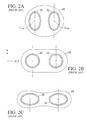
- FIG. 2A - 2C depict a prior art brace bar 28 having two holes through which the flowtubes 30 and 32 of an exemplary dual tube Coriolis mass flowmeter are inserted and secured.
- Figures 2A - 2C depict a prior art brace bar 28 having two holes through which the flowtubes 30 and 32 of an exemplary dual tube Coriolis mass flowmeter are inserted and secured.
- each flowtube 30, 32 will form an ellipse having its major axis aligned with the X axis ( Figure 2A), pass through the undeformed circular shape (Figure 2B), and then form an ellipse having its major axis aligned with the Z axis ( Figure 2C).
- the elliptical deformation of the flowtubes 30, 32 will cause the adjacent portions of the brace bar 28 to similarly deform, which in turn will cause the brace bar to stretch and compress to accommodate this deformation.
- the brace bar stretches and compresses it will push and pull the centerlines CL 30 , CL 32 of the respective flowtubes 30, 32 toward and away from each other in the Z-direction.
- the prior art brace bar 28 will convert the lateral vibrations into extraneous vibrations acting in the Z-direction, and these extraneous vibrations will couple to the driven and Coriolis modes of vibration and potentially lead to flow measurement errors.
- each brace bar 10 of the present invention is designed to prevent any lateral modes of vibration from inducing extraneous vibrations between the flowtubes in the Z-direction.
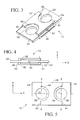
- each brace bar 10 preferably includes two separate stiffening members 34 which are joined by ideally two bridge components 36.
- Each stiffening member 34 includes a hole 38 which has a diameter approximately equal to the outer diameter of the flowtubes 14, 16.
- Each hole 38 comprises an axial centerline CL and a central axis X-X which passes through the centerline and lies in the X-Y plane of the flowmeter 12 when the brace bar 10 is installed on the flowtubes.
- each stiffening member 34 is preferably made of a rigid material, for example stainless steel, which can be readily affixed to the flowtubes, such as by welding or brazing.
- the stiffening members 34 add radial stiffness around the circumference of the flowtubes 14, 16 in order to reduce the magnitude of the elliptical deformation of the flowtubes in the presence of lateral modes of vibration.
- the stiffening members 34 are preferably substantially wider than the outer diameter of the flowtubes 14, 16.
- the stiffening members 34 are not connected to and ideally do not touch each other at the mid-plane of the flowtubes 14, 16, that is, the X-Y plane located midway between the planes of the flowtubes. Consequently, when the brace bar 10 is assembled a gap 40 preferably exists between the stiffening members 34.
- each stiffening member is ideally symmetrical about its central axis X-X to better constrain the cross section of the flowtubes 14, 16 in the Z-direction.
- the stiffening members 34 are depicted as having a generally square configuration, they could have practically any shape, including rectangular, polygonal or cylindrical.
- Each bridge component 36 includes a first edge 42, a second edge 44 which is generally parallel to the first edge, and a lip 46 which extends transversely from each edge.
- each bridge component 36 is secured to the stiffening members 34 ideally by brazing or welding.
- the bridge components 26 are sized and configured such that, when the brace bar 10 is assembled, the lip 46 of each edge 42, 44 will be aligned with the central axis X-X of a corresponding stiffening member 34.
- the bridge component 36 will effectively be joined to the stiffening members 34 only at the X-Y planes which pass through the centerlines CL 14 , CL 16 of the flowtubes.
- the first and second edges 42, 44 may each be provided with a semi-circular recess 48 to ensure that the bridge component 36 does not contact the flowtubes.
- FIGS 6A - 6C illustrate the effect that the brace bar 10 has on preventing the lateral modes of vibration from generating extraneous vibrations between the flowtubes 14, 16 in the Z-direction.
- the bridge component 36 is depicted in phantom as two separate rectangular members for purposes of simplicity.
- the normally circular cross section of each flowtube will deform elliptically in a portion of the flowtube within and adjacent the brace bar 10.
- each flowtube 14, 16 will form an ellipse having its major axis aligned with the X axis ( Figure 6A), pass through the undeformed circular shape (Figure 6B), and then form an ellipse having its major axis aligned with the Z axis ( Figure 6C).
- this elliptical deformation will cause the adjacent portions of the stiffening members 34 to similarly deform.
- the stiffening members 34 are not connected to each other at the mid-plane of the flowtubes, the deformation of the stiffening members will not push and pull the centerlines CL 14 and CL 16 of the flowtubes toward and away from each other in the Z-direction.
- the bridge components 36 are connected to the stiffening blocks 34 only through the central axes X-X, the bridge components will not deflect the centerlines CL 14 , CL 16 in the Z-direction as the stiffening blocks deform elliptically.
- the brace bar 10 will not convert the lateral vibrations into extraneous vibrations between the flowtubes in the Z-direction. Therefore, the brace bar 10 effectively decouples the lateral modes of vibration from the driven and Coriolis modes of vibration.
- brace bar 100 Another embodiment of the brace bar of the present invention is illustrated in Figures 7 - 9.
- the brace bar of this embodiment which is indicated generally by reference number 100, is shown to be similar in many respects to the brace bar 10 described above.
- brace bar 100 comprises two stiffening members 50 which each comprise a rectangular shape and a hole 52 that is offset along the central axis X-X from the geometric center of the shape.
- the brace bar 100 includes preferably two distinct bridge components 54, 56 which are connected to the stiffening members 50 on opposite sides of the holes 52.
- the bridge component 56 is wider in the X-direction than the bridge component 54.
- This configuration of the brace bar 100 may be suitable to flowmeter designs in which the lateral modes of vibration generate greater forces through the bridge component 56 than through the bridge component 54.
- brace bar 200 is shown to comprise two generally cylindrical stiffening members 58 which are connected by two substantially similar bridge components 60.
- the brace bar 200 thus comprises only two pairs of components and is therefore relatively simple to manufacture.
Landscapes
- Physics & Mathematics (AREA)
- Fluid Mechanics (AREA)
- General Physics & Mathematics (AREA)
- Measuring Volume Flow (AREA)
Abstract
The present invention is directed to a Coriolis mass flowmeter having first and second generally parallel flowtubes (14, 16) which each extend between an inlet manifold (18) and an outlet manifold (20) and comprise respective first and second centerlines that lie in corresponding parallel first and second planes, at least one force driver (22) for vibrating the first and second flowtubes in a natural mode of vibration and at least one motion sensor (24) for detecting the vibrating motion of the flowtubes. In particular, the invention comprises at least one brace bar (10) for decoupling extraneous modes of vibration in the flowtubes from the desired driven and Coriolis modes of vibration. The brace bar includes a first stiffening member having a first opening through which the first flowtube is received and secured; a second stiffening member having a second opening though which the second flowtube is received and secured; and at least one bridge component which is connected to the first stiffening member proximate the first plane and the second stiffening member proximate the second plane.
Description
- The present invention relates to a Coriolis-type mass flowmeter. More particularly, the invention relates to such a flowmeter which comprises dual parallel flowtubes and at least one brace bar connected between the flowtubes for decoupling extraneous modes of vibration from the desired the driven and Coriolis modes of vibration.
- Coriolis mass flowmeters typically comprise at least one flowtube which is connected to a section of process piping that contains a fluid to be measured, one or more force drivers for vibrating the flowtube in one of its natural modes of vibration, such as its first bending mode of vibration, and a number of motion sensors for detecting the vibrating motion of the flowtube. As the fluid flows through the vibrating flowtube it generates Coriolis forces that cause the flowtube to deform into a unique and characteristic shape, which is commonly referred to as the "Coriolis deflection". Thus, in operation the flowtube is subjected to a "driven" mode of vibration, which is generated by the force drivers, and a "Coriolis" mode of vibration, which is generated by the Coriolis forces. As is well understood by those of ordinary skill in the art, the mass flow rate and certain other properties of the fluid can be determined from the Coriolis deflection of the flowtube, which is measured by the motion sensors.
- In the field of mass flow measurement, dual tube Coriolis mass flowmeters are often preferred for their accuracy and dependability. These flowmeters typically comprise two identical parallel flowtubes, an inlet manifold which is connected between the process piping and a first end of each flowtube, and an outlet manifold which is connected between the process piping and a second end of each flowtube. The flowtubes can have various configurations, including S-shaped and U-shaped, and each flowtube lies in a plane that is parallel to the plane of the other flowtube when the flowmeter is assembled. Furthermore, the force drivers are mounted so as to vibrate the flowtubes toward and away from each other in the Z direction, which is defined herein as being perpendicular to the planes of both flowtubes. Consequently, the flowtubes vibrate 180 degrees out of phase with each other in both the driven and Coriolis modes of vibration.
- In addition to the desired driven and Coriolis modes of vibration, the flowtubes can be subjected to extraneous modes of vibration which are caused by, for example, pumps or other auxiliary equipment that are connected to the process piping. These extraneous modes of vibration, which can cause the flowtubes to vibrate either in-phase or out-of-phase with each other, can couple to the driven and Coriolis modes of vibration and thereby cause flow measurement errors. As used herein, the term "couple" as between two modes of vibration means that the energy from one mode of vibration is linked to the second mode of vibration in such a way as to cause the excitation and response of that second mode of vibration. Therefore, it is desirable to prevent any energy exchange between the extraneous modes of vibration and the driven and Coriolis modes of vibration in order to minimize the potential flow measurement errors.
- Brace bars have been employed in prior art dual tube Coriolis mass flowmeters to decouple certain extraneous modes of vibration from the desired driven and Coriolis modes of vibration. As described for example in U.S. Patent No. 5,370,002, a brace bar is typically a flat plate having two holes through which the flowtubes are passed and secured. Two separate brace bars are usually connected to the flowtubes at spaced-apart locations, and the force drivers and motion sensors are positioned between the brace bars. Consequently, the pivot points for the driven and Coriolis vibrations are shifted to the brace bars, while the pivot points for certain of the extraneous vibrations remain at the inlet and outlet manifolds. Thus, the brace bars separate the frequency of these extraneous modes of vibration from the frequency of the driven and Coriolis modes of vibration and thereby decouple the extraneous modes from the driven and Coriolis modes.
- However, certain lateral modes of vibration, that is, extraneous modes of vibration which are parallel to the planes of the flowtubes, can cause the normally round cross section of each flowtube to deform elliptically where the flowtube passes through the brace bar. Moreover, this elliptical deformation may cause traditional brace bars to stretch and compress during the vibration cycle of the lateral mode, which in turn can push and pull the centerlines of the flowtubes toward and away from each other. As a result, the flowtubes are caused to vibrate out-of-phase with each other in the Z-direction. Furthermore, since these extraneous vibrations emanate from brace bars, they can directly couple to the driven and Coriolis modes of vibration and result in flow measurement errors.
- In accordance with the present invention, these and other limitations in the prior art are overcome by providing a brace bar for a Coriolis mass flowmeter having first and second generally parallel flowtubes which each extend between an inlet manifold and an outlet manifold and comprise respective first and second centerlines that lie in corresponding parallel first and second planes, at least one force driver for vibrating the first and second flowtubes in a natural mode of vibration and at least one motion sensor for detecting the vibrating motion of the flowtubes, the brace bar being as defined in
claim 1. In a preferred form, the brace bar comprises a first stiffening member having a first opening through which the first flowtube is received and secured, a second stiffening member having a second opening though which the second flowtube is received and secured, and at least one bridge component which is connected to the first stiffening member proximate the first plane and the second stiffening member proximate the second plane. - In this manner, the first and second stiffening members will restrict the degree to which the first and second flowtubes can deform elliptically when subjected to lateral modes of vibration. In addition, the flow tubes are preferably connected through the bridge component so that any elliptical deformation of the flow tubes or stiffening members (where present) will not result in movement of the flowtubes in the Z-direction. The bridge component may be connected to the flow tubes (e.g. through the stiffening members) substantially only through the first and second planes of the flowtubes, so that elliptical deformation of the flowtubes will not cause the bridge component to deform and displace the flowtubes in the Z-direction. Therefore, the brace bar of the present invention effectively decouples the lateral modes of vibration from the driven and Coriolis modes of vibration.
- These and other objects and advantages of the present invention will be made apparent from the following detailed description, with reference to the accompanying drawings. In the drawings, the same reference numbers are used to denote similar components in the various embodiments.
-
- Figure 1 is a perspective view of an exemplary dual tube Coriolis mass flowmeter having a number of brace bars of the present invention installed thereon;
- Figures 2A - 2C are representations of the effect that certain extraneous modes of vibration can have on a prior art brace bar;
- Figures 3 - 5 are perspective, front elevation and top plan views, respectively, of the brace bar depicted in Figure 1,
- Figures 6A - 6C are representations of the effect that certain extraneous modes of vibration can have on the brace bar depicted in Figures 3 - 5;
- Figures 7 - 9 are perspective, front elevation and top plan views, respectively, of another embodiment of a brace bar of the present invention; and
- Figures 10 - 12 are perspective, front elevation and top plan views, respectively, of yet another embodiment of a brace bar of the present invention.
- Referring to Figure 1, a number of brace bars of the present invention, which are indicated generally by
reference number 10, are shown installed on an exemplary dual tube Coriolismass flowmeter 12. For purposes of this description, the rectangular coordinate system having the X, Y and Z axes oriented as shown may be used to describe the relationships between the various components of theflowmeter 12. Theflowmeter 12 includes twoflowtubes inlet manifold 18 and anoutlet manifold 20. The inlet and outlet manifolds 18, 20 are connected to respective sections of process piping (not shown), such as a pipeline. Eachflowtube flowmeter 12. Accordingly, theflowtubes flowmeter 12 also includes aforce driver 22 for vibrating the flowtubes in one of their natural modes of vibration, such as the first bending mode of vibration, and twomotion sensors 24 for detecting the vibrating motion of the flowtubes. In theexemplary flowmeter 12 depicted in Figure 1, theforce driver 22 comprises an assembly of two conventional magnet/coil pairs and eachmotion sensor 24 comprises a similar magnet/coil pair. - In operation, fluid entering the
inlet manifold 18 is split into two substantially equal streams and directed into theflowtubes force driver 22 causes theflowtubes flowtubes motion sensors 24 generate signals indicative of the Coriolis vibrations of the flowtubes and transmit these signals to a suitable processing andcontrol circuit 26, which then uses the signals to calculate the mass flow rate of the fluid in a manner that is well understood by those of ordinary skill in the art. - The exemplary dual tube Coriolis
mass flowmeter 12 is equipped with preferably four brace bars 10: two near theinlet manifold 18 and two near theoutlet manifold 20. As shown in Figure 1, each brace bar is optimally mounted to theflowtubes flowmeter 12. Thebrace bars 10 function to decouple the extraneous modes of vibration acting on theflowtubes brace bars 10 may be used for this purpose; but a minimum of one brace bar is preferably mounted near each of the inlet andoutlet manifolds - In addition to the extraneous modes of vibration which act in the Y-Z plane of the
flowmeter 12, thebrace bar 10 is particularly effective in decoupling lateral modes of vibration, that is, extraneous modes of vibration which act in the X-Y plane of the flowmeter. These lateral modes of vibration occur naturally depending on the particular flowtube shape and are easily excited by pumps or other auxiliary equipment which are connected to the process piping. Furthermore, these lateral vibrations can cause the normally round cross section of eachflowtubes brace bars 10 and in the bends in the flowtubes. Moreover, with prior art brace bars, the elliptical deformation of the flowtubes can cause the axial centerlines of the flowtubes to deflect toward and away from each other in the Z direction, thus creating an extraneous mode of vibration that can couple to the driven and Coriolis modes of vibration and lead to flow measurement errors. - This elliptical deformation effect can best be understood by reference to Figures 2A - 2C, which depict a prior
art brace bar 28 having two holes through which theflowtubes flowtubes flowtube flowtubes brace bar 28 to similarly deform, which in turn will cause the brace bar to stretch and compress to accommodate this deformation. As the brace bar stretches and compresses it will push and pull the centerlines CL30, CL32 of therespective flowtubes art brace bar 28 will convert the lateral vibrations into extraneous vibrations acting in the Z-direction, and these extraneous vibrations will couple to the driven and Coriolis modes of vibration and potentially lead to flow measurement errors. - The
brace bar 10 of the present invention is designed to prevent any lateral modes of vibration from inducing extraneous vibrations between the flowtubes in the Z-direction. Referring to Figures 3 - 5, eachbrace bar 10 preferably includes twoseparate stiffening members 34 which are joined by ideally twobridge components 36. Each stiffeningmember 34 includes ahole 38 which has a diameter approximately equal to the outer diameter of theflowtubes hole 38 comprises an axial centerline CL and a central axis X-X which passes through the centerline and lies in the X-Y plane of theflowmeter 12 when thebrace bar 10 is installed on the flowtubes. After eachbrace bar 10 is assembled, theflowtubes flowmeter 12 are inserted into theholes 38 and secured to thestiffening members 34. Each stiffeningmember 34 is preferably made of a rigid material, for example stainless steel, which can be readily affixed to the flowtubes, such as by welding or brazing. - The stiffening
members 34 add radial stiffness around the circumference of theflowtubes members 34 are preferably substantially wider than the outer diameter of theflowtubes members 34 are not connected to and ideally do not touch each other at the mid-plane of theflowtubes brace bar 10 is assembled agap 40 preferably exists between the stiffeningmembers 34. In addition, each stiffening member is ideally symmetrical about its central axis X-X to better constrain the cross section of theflowtubes stiffening members 34 are depicted as having a generally square configuration, they could have practically any shape, including rectangular, polygonal or cylindrical. - Each
bridge component 36 includes afirst edge 42, asecond edge 44 which is generally parallel to the first edge, and alip 46 which extends transversely from each edge. In addition, eachbridge component 36 is secured to thestiffening members 34 ideally by brazing or welding. Furthermore, thebridge components 26 are sized and configured such that, when thebrace bar 10 is assembled, thelip 46 of eachedge corresponding stiffening member 34. Thus, once thebrace bar 10 is attached to theflowtubes bridge component 36 will effectively be joined to thestiffening members 34 only at the X-Y planes which pass through the centerlines CL14, CL16 of the flowtubes. Moreover, as shown in Figures 3 and 5, the first andsecond edges semi-circular recess 48 to ensure that thebridge component 36 does not contact the flowtubes. - Figures 6A - 6C illustrate the effect that the
brace bar 10 has on preventing the lateral modes of vibration from generating extraneous vibrations between theflowtubes bridge component 36 is depicted in phantom as two separate rectangular members for purposes of simplicity. As was explained above, when theflowtubes brace bar 10. Thus, during each cycle of the lateral vibration the cross section of eachflowtube stiffening members 34 to similarly deform. However, since thestiffening members 34 are not connected to each other at the mid-plane of the flowtubes, the deformation of the stiffening members will not push and pull the centerlines CL14 and CL16 of the flowtubes toward and away from each other in the Z-direction. In addition, since thebridge components 36 are connected to the stiffening blocks 34 only through the central axes X-X, the bridge components will not deflect the centerlines CL14, CL16 in the Z-direction as the stiffening blocks deform elliptically. Thus, thebrace bar 10 will not convert the lateral vibrations into extraneous vibrations between the flowtubes in the Z-direction. Therefore, thebrace bar 10 effectively decouples the lateral modes of vibration from the driven and Coriolis modes of vibration. - Another embodiment of the brace bar of the present invention is illustrated in Figures 7 - 9. The brace bar of this embodiment, which is indicated generally by
reference number 100, is shown to be similar in many respects to thebrace bar 10 described above. However,brace bar 100 comprises two stiffeningmembers 50 which each comprise a rectangular shape and ahole 52 that is offset along the central axis X-X from the geometric center of the shape. In addition, thebrace bar 100 includes preferably twodistinct bridge components stiffening members 50 on opposite sides of theholes 52. As is evident from Figure 9, thebridge component 56 is wider in the X-direction than thebridge component 54. This configuration of thebrace bar 100 may be suitable to flowmeter designs in which the lateral modes of vibration generate greater forces through thebridge component 56 than through thebridge component 54. - Yet another embodiment of a brace bar of the present invention is shown in Figures 10 - 12. The brace bar of this embodiment, which is indicated generally by
reference number 200, is shown to comprise two generallycylindrical stiffening members 58 which are connected by two substantiallysimilar bridge components 60. Thebrace bar 200 thus comprises only two pairs of components and is therefore relatively simple to manufacture. - It should be recognized that, while the present invention has been described in relation to the preferred embodiments thereof, those skilled in the art may develop a wide variation of structural and operational details without departing from the principles of the invention. For example, the various elements illustrated in the different embodiments may be combined in a manner not illustrated above. Therefore, the appended claims are to be construed to cover all equivalents falling within the scope of the invention as defined in the claims.
Claims (10)
- For use with a Coriolis mass flowmeter (12) having first and second generally parallel flowtubes (14, 16) which each extend between an inlet manifold (18) and an outlet manifold (20) and comprise respective first and second centerlines that lie in corresponding parallel first and second planes (X-X), at least one force driver (22) for vibrating the first and second flowtubes (14, 16) in a natural mode of vibration and at least one motion sensor (24) for detecting the vibrating motion of the flowtubes, at least one brace bar (10), characterised in that the brace bar includes:at least one bridge component (36, 54, 56, 60) which in use is connected to the first flow tube (14, 16)proximate the first plane (X-X) and the second flow tube (14, 16) proximate the second plane (X-X).
- The brace bar of claim 1, further characterised in that the brace bar (10) comprises a first stiffening member (34, 50, 58) having a first opening (38, 52) through which the first flowtube is received and secured, a second stiffening member (34, 50, 58) having a second opening (38, 52) through which the second flowtube is received and secured, the bridge component (36, 54, 56, 60) being secured between the first and second stiffening members (34, 50, 58).
- The brace bar (10) of claim 2, further characterised in that each stiffening member (34, 50) is generally rectangular in a plane perpendicular to the first and second centerlines.
- The brace bar (10) of claim 2 or 3, further characterised in that each stiffening member (34, 50, 58) is generally symmetrical about its corresponding first or second plane.
- The brace bar (10) of claim 2, wherein each stiffening member (58) is generally cylindrical.
- The brace bar of any preceding claim, further characterised in that the bridge component (36, 54, 56, 60) comprises first and second spaced-apart, generally parallel edges (42, 44) and the bridge component is connected to the flow tubes (14, 16) proximate the first and second edges.
- The brace bar (10) of claim 6, further characterised in that the bridge (36, 54, 56, 60) component comprises a lip (46) extending generally transversely from the first and second edges (42, 44) and the bridge component is connected to the stiffening members through the lips.
- The brace bar (10) of any preceding claim, further characterised in that it comprises a single said bridge component (36).
- The brace bar (10) of any preceding claim, further characterised in that it comprises a pair of said bridge components (54, 56, 60), the bridge components being disposed on either side of the flow tubes.
- A Coriolis mass flowmeter (12) having first and second generally parallel flowtubes (14, 16) which each extend between an inlet manifold and an outlet manifold (18, 20) and comprise respective first and second centerlines that lie in corresponding parallel first and second planes (X-X), at least one force driver (22) for vibrating the first and second flowtubes (14, 16) in a natural mode of vibration and at least one motion sensor (24) for detecting the vibrating motion of the flowtubes, characterised in that the flowmeter comprises a brace bar (10) as defined in any preceding claim.
Applications Claiming Priority (2)
| Application Number | Priority Date | Filing Date | Title |
|---|---|---|---|
| US911000 | 2001-07-23 | ||
| US09/911,000 US6415668B1 (en) | 2001-07-23 | 2001-07-23 | De-coupling extraneous modes of vibration in a coriolis mass flowmeter |
Publications (1)
| Publication Number | Publication Date |
|---|---|
| EP1279935A2 true EP1279935A2 (en) | 2003-01-29 |
Family
ID=25429625
Family Applications (1)
| Application Number | Title | Priority Date | Filing Date |
|---|---|---|---|
| EP02255152A Withdrawn EP1279935A2 (en) | 2001-07-23 | 2002-07-23 | Method for decoupling extraneous modes of vibration in a Coriolis mass flowmeter |
Country Status (2)
| Country | Link |
|---|---|
| US (1) | US6415668B1 (en) |
| EP (1) | EP1279935A2 (en) |
Cited By (6)
| Publication number | Priority date | Publication date | Assignee | Title |
|---|---|---|---|---|
| DE102004053883A1 (en) * | 2004-11-04 | 2006-05-11 | Endress + Hauser Flowtec Ag | Vibration-type fluid flow sensor has casing and supports forming external vibrator and bypass sensor tube with laterally vibrating exciter and sensor |
| EP1684055A1 (en) * | 2005-01-21 | 2006-07-26 | Krohne AG | Coriolis mass flow meter |
| US7216549B2 (en) | 2004-11-04 | 2007-05-15 | Endress + Hauser Flowtec Ag | Vibration-type measurement transducer |
| DE102005062004A1 (en) * | 2005-12-22 | 2007-06-28 | Endress + Hauser Flowtec Ag | Mass converter housing for use in coriolis mass through-flow measurement has an inner section and a vibrating mass pipe which has greater dead-point stability |
| US7325462B2 (en) | 2005-12-22 | 2008-02-05 | Endress + Hauser Flowtec Ag | Measuring transducer of vibration-type |
| US7360451B2 (en) | 2005-12-22 | 2008-04-22 | Endress + Hauser Flowtec Ag | Measuring transducer of vibration-type |
Families Citing this family (44)
| Publication number | Priority date | Publication date | Assignee | Title |
|---|---|---|---|---|
| US6666098B2 (en) * | 2001-05-23 | 2003-12-23 | Endress + Hauser Flowtec Ag | Vibratory transducer |
| US6598489B1 (en) * | 2002-03-29 | 2003-07-29 | Micro Motion, Inc. | Balance bar having a reduced axial thermal stress resulting from high temperature manufacturing methods |
| US6782762B2 (en) * | 2002-09-10 | 2004-08-31 | Direct Measurement Corporation | Coriolis flowmeter with improved zero stability |
| WO2005019780A1 (en) * | 2003-08-26 | 2005-03-03 | Siemens Flow Instruments A/S | A coupling between loops of a coriolis mass flow meter |
| US7350421B2 (en) | 2004-12-13 | 2008-04-01 | Endress + Hauser Flowtec Ag | Vibratory measurement transducer |
| DE102004060115A1 (en) * | 2004-12-13 | 2006-06-14 | Endress + Hauser Flowtec Ag | Transducer of the vibration type |
| JP4254966B2 (en) * | 2006-03-14 | 2009-04-15 | 株式会社オーバル | Coriolis flowmeter with vibration direction regulating means |
| DE102006034274B4 (en) * | 2006-07-21 | 2012-06-28 | Krohne Ag | The mass flow meter |
| DE102008007742A1 (en) * | 2007-04-25 | 2008-11-06 | Krohne Ag | Coriolis mass flowmeter |
| JP4884408B2 (en) * | 2008-02-01 | 2012-02-29 | 株式会社オーバル | Coriolis flow meter |
| CN101983319B (en) * | 2008-04-02 | 2013-03-13 | 微动公司 | Brace bar with a partial bond |
| DE102009027580A1 (en) | 2009-07-09 | 2011-01-13 | Endress + Hauser Flowtec Ag | Vibration-type transducers and in-line meter with such a transducer |
| DE102009001472A1 (en) | 2009-03-11 | 2010-09-16 | Endress + Hauser Flowtec Ag | Vibration-type transducers and in-line meter with such a transducer |
| CN102348961B (en) | 2009-03-11 | 2015-04-22 | 恩德斯+豪斯流量技术股份有限公司 | Measuring systems for media flowing in pipelines |
| CN102686984A (en) | 2009-12-03 | 2012-09-19 | 普里西姆有限公司 | Coriolis mass flow meter and components thereof |
| DE102010039627A1 (en) | 2010-08-20 | 2012-02-23 | Endress + Hauser Flowtec Ag | Vibration-type measuring transducer for e.g. flow/density/viscosity measuring device, used for registering mass flow rate of medium flowing in pipeline, has imaginary longitudinal-section plane extending between respective measuring tubes |
| EP2516972B1 (en) | 2009-12-21 | 2021-11-10 | Endress+Hauser Flowtec AG | Vibration type sensor |
| DE102009055069A1 (en) | 2009-12-21 | 2011-06-22 | Endress + Hauser Flowtec Ag | Vibration-type measuring sensor for detecting e.g. mass flow rate of gas and for producing Coriolis forces in process measurement- and automation system, has tube arrangement exhibiting sectional plane running between measuring tubes |
| RU2551481C2 (en) | 2010-09-02 | 2015-05-27 | Эндресс+Хаузер Флоутек Аг | Measuring system for measurement of density and/or norm of mass flow rate and/or viscosity of fluid environment proceeding in pipeline and use of measuring system |
| EP2659236B1 (en) | 2010-12-30 | 2019-07-03 | Endress+Hauser Flowtec AG | Measuring sensor of the vibration type and measuring system formed thereby |
| EP2705334B1 (en) | 2011-05-02 | 2018-01-24 | Endress+Hauser Flowtec AG | Vibration-type measuring sensor and measuring system formed therewith |
| CN104204735B (en) * | 2012-04-03 | 2017-12-29 | 恩德斯+豪斯流量技术股份有限公司 | Transducer of vibration type |
| EP2906915B1 (en) | 2012-10-11 | 2022-04-20 | Endress+Hauser Flowtec AG | Measuring system for determining a volume flow and/or a volume flow rate of a medium flowing in a pipe line |
| DE102012109729A1 (en) | 2012-10-12 | 2014-05-15 | Endress + Hauser Flowtec Ag | Measuring system for determining volumetric flow during measuring interval of total flowed volume of flowing medium, particularly liquid or gas, has vibration element for guiding flowing portion of medium, where vibration element has lumen |
| US9952077B2 (en) * | 2013-04-18 | 2018-04-24 | Micron Motion, Inc. | Self-aligning brace bar |
| CN105705912B (en) * | 2013-11-13 | 2019-11-19 | 高准公司 | Struts for Vibration Meters |
| WO2015085025A1 (en) | 2013-12-04 | 2015-06-11 | Gilbarco Inc. | Fuel dispenser coriolis flow meter |
| CN107209038B (en) | 2014-12-22 | 2020-11-27 | 恩德斯+豪斯流量技术股份有限公司 | Coriolis mass flow measuring device or density measuring device |
| DE102015107769A1 (en) | 2015-05-18 | 2016-11-24 | Endress + Hauser Flowtec Ag | Coriolis mass flowmeter or density meter |
| DE102014119427A1 (en) | 2014-12-22 | 2016-06-23 | Endress + Hauser Flowtec Ag | Coriolis mass flowmeter |
| DE102015003365A1 (en) * | 2015-03-16 | 2016-09-22 | Rota Yokogawa Gmbh & Co Kg | Coriolis mass flowmeter |
| DE102015118347A1 (en) * | 2015-10-27 | 2017-04-27 | Endress+Hauser Flowtec Ag | Sensor with a measuring cable that can be excited to oscillate |
| WO2018164670A1 (en) * | 2017-03-07 | 2018-09-13 | Micro Motion, Inc. | Driver, sensor, and brace bar for a vibratory conduit |
| DE102017115400A1 (en) | 2017-07-10 | 2019-01-10 | Endress + Hauser Messtechnik Gmbh+Co. Kg | measuring system |
| CN118960884A (en) | 2017-08-29 | 2024-11-15 | 高准公司 | Integrated support rod |
| DE102018005197B3 (en) * | 2018-06-29 | 2019-11-14 | Rota Yokogawa Gmbh & Co. Kg | Coriolis mass flow and density meter with reduced pressure dependence |
| EP4679456A2 (en) | 2019-05-17 | 2026-01-14 | Metatomic, Inc. | Systems for molten salt reactor fuel-salt preparation |
| RU201254U1 (en) * | 2020-08-26 | 2020-12-07 | Алексей Анатольевич Воронцов | VIBRATION MEASURING CONVERTER |
| DE102020123162A1 (en) | 2020-09-04 | 2022-03-10 | Endress+Hauser Flowtec Ag | Method for operating a measuring arrangement with a Coriolis measuring device and measuring arrangement |
| DE102020133850A1 (en) | 2020-12-16 | 2022-06-23 | Endress+Hauser Flowtec Ag | Method of operating a flow meter and metering system |
| CN112857494A (en) * | 2021-01-21 | 2021-05-28 | 沃森测控技术(河北)有限公司 | Bent pipe type Coriolis flowmeter gusset plate |
| CN113155216A (en) * | 2021-01-21 | 2021-07-23 | 沃森测控技术(河北)有限公司 | Double-tube type Coriolis flowmeter fixing support |
| DE102021111564A1 (en) | 2021-05-04 | 2022-11-10 | Endress+Hauser (Deutschland) Gmbh+Co. Kg | System and method for providing a free-flowing print application medium with a predeterminable viscosity for a printing unit |
| CN117309068A (en) * | 2023-10-30 | 2023-12-29 | 青岛澳威流体计量有限公司 | Flowmeter and vibrating piece thereof |
Family Cites Families (4)
| Publication number | Priority date | Publication date | Assignee | Title |
|---|---|---|---|---|
| US4781069A (en) * | 1986-06-05 | 1988-11-01 | Exac Corporation | Mode selection apparatus for multiple tube coriolis type mass flow meters |
| US5054326A (en) * | 1990-03-05 | 1991-10-08 | The Foxboro Company | Density compensator for coriolis-type mass flowmeters |
| US5370002A (en) | 1993-07-23 | 1994-12-06 | Micro Motion, Inc. | Apparatus and method for reducing stress in the brace bar of a Coriolis effect mass flow meter |
| US5497666A (en) * | 1994-07-20 | 1996-03-12 | Micro Motion, Inc. | Increased sensitivity coriolis effect flowmeter using nodal-proximate sensors |
-
2001
- 2001-07-23 US US09/911,000 patent/US6415668B1/en not_active Expired - Lifetime
-
2002
- 2002-07-23 EP EP02255152A patent/EP1279935A2/en not_active Withdrawn
Cited By (6)
| Publication number | Priority date | Publication date | Assignee | Title |
|---|---|---|---|---|
| DE102004053883A1 (en) * | 2004-11-04 | 2006-05-11 | Endress + Hauser Flowtec Ag | Vibration-type fluid flow sensor has casing and supports forming external vibrator and bypass sensor tube with laterally vibrating exciter and sensor |
| US7216549B2 (en) | 2004-11-04 | 2007-05-15 | Endress + Hauser Flowtec Ag | Vibration-type measurement transducer |
| EP1684055A1 (en) * | 2005-01-21 | 2006-07-26 | Krohne AG | Coriolis mass flow meter |
| DE102005062004A1 (en) * | 2005-12-22 | 2007-06-28 | Endress + Hauser Flowtec Ag | Mass converter housing for use in coriolis mass through-flow measurement has an inner section and a vibrating mass pipe which has greater dead-point stability |
| US7325462B2 (en) | 2005-12-22 | 2008-02-05 | Endress + Hauser Flowtec Ag | Measuring transducer of vibration-type |
| US7360451B2 (en) | 2005-12-22 | 2008-04-22 | Endress + Hauser Flowtec Ag | Measuring transducer of vibration-type |
Also Published As
| Publication number | Publication date |
|---|---|
| US6415668B1 (en) | 2002-07-09 |
Similar Documents
| Publication | Publication Date | Title |
|---|---|---|
| US6415668B1 (en) | De-coupling extraneous modes of vibration in a coriolis mass flowmeter | |
| US7475603B2 (en) | Measurement transducer of vibration-type | |
| US6360614B1 (en) | Method and corresponding sensors for measuring mass flow rate | |
| EP0246510A1 (en) | Single tube parallel flow coriolis mass flow sensor | |
| CN100565127C (en) | vibration sensor | |
| US6782762B2 (en) | Coriolis flowmeter with improved zero stability | |
| JPH09501493A (en) | Apparatus and method for reducing stress in a brace bar of a Coriolis effect mass flow meter | |
| US7472607B2 (en) | Measurement transducer of vibration type | |
| CA2710172A1 (en) | Measuring transducer of vibration-type | |
| JP5193185B2 (en) | Coriolis flow meter with a single flow conduit, method of operation, and method of manufacture | |
| US7490521B2 (en) | Measurement transducer of vibration type | |
| US7540203B2 (en) | Device for measuring the mass rate of flow having two measuring tubes joined by a stiffened connector | |
| US8573067B2 (en) | Flow meter including a balance member | |
| US20160363472A1 (en) | Coriolis flowsensor | |
| EP1726921B1 (en) | Coriolis flowmeter | |
| WO2001013072A2 (en) | Method and apparatus for coriolis flowmeter having an accuracy enhancing balance bar | |
| EP2430406B1 (en) | A flow meter including a balanced reference member and its method | |
| US6553845B2 (en) | Coriolis flowmeter utilizing three-forked plate vibrator mode | |
| KR20060124737A (en) | Coriolis Flowmeter | |
| CN105043477B (en) | Vibrating flowing device and method for manufacturing vibrating flowing device | |
| US10215605B1 (en) | Coriolis mass flowmeter and sensor assembly thereof | |
| JP3555652B2 (en) | Coriolis mass flowmeter | |
| CN115135969B (en) | Mode-separating resonator for the balance bar of a Coriolis flowmeter | |
| AU2013200990B2 (en) | A flow meter including a balanced reference member | |
| WO2024072431A1 (en) | Flowmeter magnetic shielding apparatus and method |
Legal Events
| Date | Code | Title | Description |
|---|---|---|---|
| PUAI | Public reference made under article 153(3) epc to a published international application that has entered the european phase |
Free format text: ORIGINAL CODE: 0009012 |
|
| AK | Designated contracting states |
Designated state(s): AT BE BG CH CY CZ DE DK EE ES FI FR GB GR IE IT LI LU MC NL PT SE SK TR |
|
| AX | Request for extension of the european patent |
Extension state: AL LT LV MK RO SI |
|
| STAA | Information on the status of an ep patent application or granted ep patent |
Free format text: STATUS: THE APPLICATION IS DEEMED TO BE WITHDRAWN |
|
| 18D | Application deemed to be withdrawn |
Effective date: 20050201 |