EP1279917A1 - Self-defense arm - Google Patents
Self-defense arm Download PDFInfo
- Publication number
- EP1279917A1 EP1279917A1 EP01918027A EP01918027A EP1279917A1 EP 1279917 A1 EP1279917 A1 EP 1279917A1 EP 01918027 A EP01918027 A EP 01918027A EP 01918027 A EP01918027 A EP 01918027A EP 1279917 A1 EP1279917 A1 EP 1279917A1
- Authority
- EP
- European Patent Office
- Prior art keywords
- arm
- self
- defense
- cartridges
- electric spark
- Prior art date
- Legal status (The legal status is an assumption and is not a legal conclusion. Google has not performed a legal analysis and makes no representation as to the accuracy of the status listed.)
- Granted
Links
Images


Classifications
-
- F—MECHANICAL ENGINEERING; LIGHTING; HEATING; WEAPONS; BLASTING
- F41—WEAPONS
- F41C—SMALLARMS, e.g. PISTOLS, RIFLES; ACCESSORIES THEREFOR
- F41C3/00—Pistols, e.g. revolvers
- F41C3/04—Starting pistols; Alarm pistols
-
- F—MECHANICAL ENGINEERING; LIGHTING; HEATING; WEAPONS; BLASTING
- F41—WEAPONS
- F41A—FUNCTIONAL FEATURES OR DETAILS COMMON TO BOTH SMALLARMS AND ORDNANCE, e.g. CANNONS; MOUNTINGS FOR SMALLARMS OR ORDNANCE
- F41A19/00—Firing or trigger mechanisms; Cocking mechanisms
- F41A19/58—Electric firing mechanisms
-
- F—MECHANICAL ENGINEERING; LIGHTING; HEATING; WEAPONS; BLASTING
- F41—WEAPONS
- F41A—FUNCTIONAL FEATURES OR DETAILS COMMON TO BOTH SMALLARMS AND ORDNANCE, e.g. CANNONS; MOUNTINGS FOR SMALLARMS OR ORDNANCE
- F41A19/00—Firing or trigger mechanisms; Cocking mechanisms
- F41A19/58—Electric firing mechanisms
- F41A19/60—Electric firing mechanisms characterised by the means for generating electric energy
- F41A19/61—Inductive generators
-
- F—MECHANICAL ENGINEERING; LIGHTING; HEATING; WEAPONS; BLASTING
- F41—WEAPONS
- F41A—FUNCTIONAL FEATURES OR DETAILS COMMON TO BOTH SMALLARMS AND ORDNANCE, e.g. CANNONS; MOUNTINGS FOR SMALLARMS OR ORDNANCE
- F41A19/00—Firing or trigger mechanisms; Cocking mechanisms
- F41A19/58—Electric firing mechanisms
- F41A19/68—Electric firing mechanisms for multibarrel guns or multibarrel rocket launchers or multicanisters
-
- F—MECHANICAL ENGINEERING; LIGHTING; HEATING; WEAPONS; BLASTING
- F41—WEAPONS
- F41A—FUNCTIONAL FEATURES OR DETAILS COMMON TO BOTH SMALLARMS AND ORDNANCE, e.g. CANNONS; MOUNTINGS FOR SMALLARMS OR ORDNANCE
- F41A33/00—Adaptations for training; Gun simulators
- F41A33/02—Light- or radiation-emitting guns ; Light- or radiation-sensitive guns; Cartridges carrying light emitting sources, e.g. laser
Definitions
- the present invention relates to a manual portable fire arm and is intended for use by civil persons for self-defense by shooting with traumatizing elements or by audio and light signals (shot flash).
- a civil self-defense arm which is a so-called «gas» arm: gas guns and revolvers and cartridges for them.
- Appearance, sizes, designs of main mechanisms and a caliber of the used cartridges of this arm usually corresponds to military arm, or in other words they are copies of the military arm as to its structural design.
- Cartridges for such arm do not contain bullets, and equipment of cases is composed of a mixture of smoke powder and any active substance. Cases of cartridges are provided with electric spark igniter of striking action.
- various structural concepts are utilized. For example these problems are solved by making a guntube and other parts of a material which has intentionally lower strengths, which can lead to a crack of the guntube from pressure of powder gasses during shooting with a military cartridge.
- the axis of the cartridge holder and a channel of the gun tube is offset, or a strong partition is installed in the channel of the guntube (without a complete blocking of the cross-section) which is composed of a hard alloy or a metal-ceramic. Nevertheless, the possibility of criminal use of this arm with the application of military cartridges is not excluded. Cases are widely known when such an arm is redesigned since it is available.
- arms are known in which cartridges are activated by electric current.
- Mainly such structural solutions are used in a high caliber arm which is installed mainly on flying apparatuses and ships.
- aviation cassettes for signal cartridges and cartridges of various interferences are used in a high caliber arm which is installed mainly on flying apparatuses and ships.
- the electrical method is used for the purpose of providing a successive shooting of charges, which would be very difficult to realize with the use of electric spark ignitors.
- a device is selected(see patent of RF no. 2079087 C1, F 41 C 300, May 10, 1997) which discloses a self-defense arm including a gun tube and tubes formed as cases of cartridges.
- This device has a substantial disadvantage-the presence of cumbersome-striking-activating mechanism. Big sizes and mass of striking-activating mechanism are substantially determined by the necessity to perform additional functions, such as distribution of strikes of a striker (main) against peripheral strikers, which in turn requires introduction into the striking-activating mechanism of additional kinematically connected massive parts.
- the objective of the present invention is to create an efficient and reliable self-defense arm, which excludes the possibility of its direct criminal application with the use of military cartridges, even also after an available conversion in household conditions.
- a self-defense arm containing a holder of cartridges, gun barrels formed as cartridges with an electrical spark igniter, and in which an activating mechanism of triggering includes a pulse magneto-electricor pulse electro-chemical current source, electrically connected with a distributing device which contains a contact block.
- a comparative analysis of the proposed solution with the prototype and other technical solutions in this technical area shows that the claimed solution is characterized by a gun tube formed as a cartridge case with an electric spark ignitor and an activating mechanism. This allowed to completely exclude a possibility of direct criminal application of this self-defense device. At the same time, a general level of energy is provided for achieving a stopping action, but a limitation of specific energy is maintained. A total speed of a bullet can not be increased over 150 m/s (speed of bullet for inflicting heavy body injuries must be 180-200 m/s). Moreover, electric spark ignitors are not in a free commerce and during its manufacture a very strict account is carried out.
- the design of the activating mechanism with the source of electrical current allows to exclude a possibility of its criminal use, since all military cartridges of a shooting arm are provided with capsules-spark igniters of a striking action.
- the arm is equipped with a distributing device (a switching mechanism, which provides a predetermined sequence of shooting and indexing of gun tube which has been activated.
- the arm is composed of four cartridge cases (1) with an electric spark igniter (2) installed in a casing (3).
- a source of electric current (5) and a distributing device (switching mechanism) (6) are arranged in a handle (4).
- a source of electric current a mechanical magneto-electric pulse generator is used. It is possible to use other sources of current, for example an electrochemical source (battery).
- Cartridge cases are retained in nests of the casing and pressed to contacts (7) by springy elements.
- a block of contacts is formed as a separate assembly which is immovably fixed in the handle. The mechanism of switching is controlled a by starting key through a rod, simultaneously the starting controls a button of a car generator.
- the arm operates in the following manner.
- One or several cartridges composed of a case with an electric spark igniter, a throwing charge and a body to be thrown (signal pirotechnical element, rubber bullet, light-sound element) are introduced into the casing of the arm, and the starting key is pressed.
- a displacement of a pusher of the distributing device is performed (in other words a switching (of channels) of contacts in the contact block is carried out), and also a displacement of the button of the current generator which is triggered during a further movement of the key.
- Current pulse passes through the switch to a corresponding contact and electric spark igniter. The cartridge is triggered.
- a successive triggering of the remaining cartridges is performed.
- the design of the gun tube as a cartridge with an electric spark igniter and the use of a source of electric current for activation allowed to create an efficient self-defense arm, excluding the possibility of its criminal use for direct application (possibility of increasing a striking factor).
Landscapes
- Engineering & Computer Science (AREA)
- General Engineering & Computer Science (AREA)
- Physics & Mathematics (AREA)
- Optics & Photonics (AREA)
- Aiming, Guidance, Guns With A Light Source, Armor, Camouflage, And Targets (AREA)
- Burglar Alarm Systems (AREA)
- Medicines That Contain Protein Lipid Enzymes And Other Medicines (AREA)
- Emergency Lowering Means (AREA)
- Catching Or Destruction (AREA)
Abstract
Description
- The present invention relates to a manual portable fire arm and is intended for use by civil persons for self-defense by shooting with traumatizing elements or by audio and light signals (shot flash).
- Creation of civil arm for self defense requires to satisfy some requirements. First of all, a limitation for specific energy (relationship between energy and area of a cross-section of a bullet) must be maintained. This magnitude must be less or equal to 0.5 J/mm, since when its magnitude is greater infliction of heavy body injuries is possible. At the same time, the general level of energy must be sufficiently high (∼100J), otherwise effects of an arm with a stopping action will not be achieved. The stopping action is characterized by an ability to transfer a certain quantity of kinetic energy to an obstacle with a minimal depth of penetration. Action of a self-defense arm must not lead to heavy body injuries, maiming, and the arm itself must prevent a possibility of its criminal use for a direct application.
- A civil self-defense arm is known, which is a so-called «gas» arm: gas guns and revolvers and cartridges for them.
- Appearance, sizes, designs of main mechanisms and a caliber of the used cartridges of this arm usually corresponds to military arm, or in other words they are copies of the military arm as to its structural design. Cartridges for such arm do not contain bullets, and equipment of cases is composed of a mixture of smoke powder and any active substance. Cases of cartridges are provided with electric spark igniter of striking action. For the purpose of preventing use of in such an arm of military cartridges, various structural concepts are utilized. For example these problems are solved by making a guntube and other parts of a material which has intentionally lower strengths, which can lead to a crack of the guntube from pressure of powder gasses during shooting with a military cartridge. For providing a possibility of criminal application, the axis of the cartridge holder and a channel of the gun tube is offset, or a strong partition is installed in the channel of the guntube (without a complete blocking of the cross-section) which is composed of a hard alloy or a metal-ceramic. Nevertheless, the possibility of criminal use of this arm with the application of military cartridges is not excluded. Cases are widely known when such an arm is redesigned since it is available.
- Also, arms are known in which cartridges are activated by electric current. Mainly such structural solutions are used in a high caliber arm which is installed mainly on flying apparatuses and ships. For example, aviation cassettes for signal cartridges and cartridges of various interferences.
- In a portable shooting arm, electrical methods of triggering of cartridges did not find their application.
- A solution for use of electrical method of shooting in a shooting arm is known (see U.S. patent no. 3,854,231 F 41 C 19/12 December 17, 1974). In this patent an arm is considered, in which cartridges composed of a great number of successively shooting charges are used.
- In this case the electrical method is used for the purpose of providing a successive shooting of charges, which would be very difficult to realize with the use of electric spark ignitors.
- As a prototype, a device is selected(see patent of RF no. 2079087 C1, F 41 C 300, May 10, 1997) which discloses a self-defense arm including a gun tube and tubes formed as cases of cartridges.
- This device has a substantial disadvantage-the presence of cumbersome-striking-activating mechanism. Big sizes and mass of striking-activating mechanism are substantially determined by the necessity to perform additional functions, such as distribution of strikes of a striker (main) against peripheral strikers, which in turn requires introduction into the striking-activating mechanism of additional kinematically connected massive parts.
- The objective of the present invention is to create an efficient and reliable self-defense arm, which excludes the possibility of its direct criminal application with the use of military cartridges, even also after an available conversion in household conditions.
- This objective is achieved in that in a self-defense arm, containing a holder of cartridges, gun barrels formed as cartridges with an electrical spark igniter, and in which an activating mechanism of triggering includes a pulse magneto-electricor pulse electro-chemical current source, electrically connected with a distributing device which contains a contact block.
- A comparative analysis of the proposed solution with the prototype and other technical solutions in this technical area shows that the claimed solution is characterized by a gun tube formed as a cartridge case with an electric spark ignitor and an activating mechanism. This allowed to completely exclude a possibility of direct criminal application of this self-defense device. At the same time, a general level of energy is provided for achieving a stopping action, but a limitation of specific energy is maintained. A total speed of a bullet can not be increased over 150 m/s (speed of bullet for inflicting heavy body injuries must be 180-200 m/s). Moreover, electric spark ignitors are not in a free commerce and during its manufacture a very strict account is carried out.
- In the claimed self-defense arm, the design of the activating mechanism with the source of electrical current allows to exclude a possibility of its criminal use, since all military cartridges of a shooting arm are provided with capsules-spark igniters of a striking action.
- For providing a shooting with special cartridges, the arm is equipped with a distributing device (a switching mechanism, which provides a predetermined sequence of shooting and indexing of gun tube which has been activated.
-
- Figure 1 shows a general view of a self-defense arm.
- Figure 2 shows a front view.
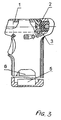
- Figure 3 shows a variant of use of the arm with a cartridge case.
- The arm is composed of four cartridge cases (1) with an electric spark igniter (2) installed in a casing (3). A source of electric current (5) and a distributing device (switching mechanism) (6) are arranged in a handle (4). As a source of electric current, a mechanical magneto-electric pulse generator is used. It is possible to use other sources of current, for example an electrochemical source (battery). Cartridge cases are retained in nests of the casing and pressed to contacts (7) by springy elements. A block of contacts is formed as a separate assembly which is immovably fixed in the handle. The mechanism of switching is controlled a by starting key through a rod, simultaneously the starting controls a button of a car generator.
- The arm operates in the following manner. One or several cartridges composed of a case with an electric spark igniter, a throwing charge and a body to be thrown (signal pirotechnical element, rubber bullet, light-sound element) are introduced into the casing of the arm, and the starting key is pressed.
- During pressing, a displacement of a pusher of the distributing device is performed (in other words a switching (of channels) of contacts in the contact block is carried out), and also a displacement of the button of the current generator which is triggered during a further movement of the key. Current pulse passes through the switch to a corresponding contact and electric spark igniter. The cartridge is triggered. During subsequent pressing, a successive triggering of the remaining cartridges is performed.
- The operation of the self-defense arm when the cassette is formed with one nest is performed analogously.
- The design of the gun tube as a cartridge with an electric spark igniter and the use of a source of electric current for activation allowed to create an efficient self-defense arm, excluding the possibility of its criminal use for direct application (possibility of increasing a striking factor).
Claims (1)
- A self-defense arm, containing a holder of cartridges, guntubes formed as cartridge cases, and an activating mechanism, characterized in that the cartridges cases are formed with an electric spark igniters, and the activating mechanism includes a pulse magneto electric or a pulse electrochemical current source which is electrically connected with a distributing device which contains a contact block.
Applications Claiming Priority (3)
| Application Number | Priority Date | Filing Date | Title |
|---|---|---|---|
| RU2000104998 | 2000-02-29 | ||
| RU2000104998/02A RU2172460C1 (en) | 2000-02-29 | 2000-02-29 | Self-defence weapon |
| PCT/RU2001/000082 WO2001065196A1 (en) | 2000-02-29 | 2001-02-26 | Self-defense arm |
Publications (3)
| Publication Number | Publication Date |
|---|---|
| EP1279917A1 true EP1279917A1 (en) | 2003-01-29 |
| EP1279917A4 EP1279917A4 (en) | 2003-10-15 |
| EP1279917B1 EP1279917B1 (en) | 2007-11-28 |
Family
ID=20231263
Family Applications (1)
| Application Number | Title | Priority Date | Filing Date |
|---|---|---|---|
| EP01918027A Expired - Lifetime EP1279917B1 (en) | 2000-02-29 | 2001-02-26 | Self-defense arm |
Country Status (5)
| Country | Link |
|---|---|
| US (1) | US20040068909A1 (en) |
| EP (1) | EP1279917B1 (en) |
| DE (1) | DE60131642T2 (en) |
| RU (1) | RU2172460C1 (en) |
| WO (1) | WO2001065196A1 (en) |
Families Citing this family (22)
| Publication number | Priority date | Publication date | Assignee | Title |
|---|---|---|---|---|
| RU2216704C2 (en) * | 2002-01-03 | 2003-11-20 | Государственное унитарное предприятие "Конструкторское бюро приборостроения" | Multibarrel pistol |
| RU2211429C1 (en) * | 2002-04-15 | 2003-08-27 | Титков Олег Павлович | Revolver-type mortar |
| RU2229083C1 (en) * | 2002-09-17 | 2004-05-20 | Федеральное государственное унитарное предприятие "Ижевский механический завод" | Self-defense weapon |
| RU2229666C1 (en) * | 2002-09-23 | 2004-05-27 | Федеральное государственное унитарное предприятие "Ижевский механический завод" | Self-defense weapon |
| RU2213923C1 (en) * | 2002-10-24 | 2003-10-10 | Бидеев Геннадий Александрович | Self-defense weapon |
| RU2218538C1 (en) * | 2002-10-24 | 2003-12-10 | Бидеев Геннадий Александрович | Self-defense weapon |
| WO2004038319A1 (en) * | 2002-10-24 | 2004-05-06 | Gennadij Alexandrovich Bideev | Self-defence arm |
| RU2250431C2 (en) * | 2003-03-03 | 2005-04-20 | Федеральное государственное унитарное предприятие "Ижевский механический завод" | Self-defense weapon |
| RU2260762C2 (en) * | 2003-07-03 | 2005-09-20 | Коротков Евгений Борисович | Weapon for self-defense |
| RU2235265C1 (en) * | 2003-07-18 | 2004-08-27 | Сухолитко Валентин Афанасьевич | Automatic weapon |
| RU2265176C2 (en) * | 2003-08-20 | 2005-11-27 | Калинин Сергей Алексеевич | Device for firing (modifications) |
| RU2236664C1 (en) * | 2003-09-30 | 2004-09-20 | Аленин Алексей Иванович | Barrelless self-protection arms with electric cartridges |
| RU2243476C1 (en) * | 2004-01-08 | 2004-12-27 | Федеральное государственное унитарное предприятие "Ижевский механический завод" | Self-defence weapon |
| RU2256141C1 (en) * | 2004-02-16 | 2005-07-10 | Открытое акционерное общество "Кировский завод "Маяк" | Firing arrangement |
| RU2298758C1 (en) * | 2005-09-07 | 2007-05-10 | Алексей Иванович Аленин | Self-defense weapon |
| RU2310805C1 (en) * | 2006-07-26 | 2007-11-20 | Государственное Унитарное Предприятие "Конструкторское Бюро Приборостроения" (Гуп "Кбп") | Multibarreled firing module |
| RU2499971C1 (en) * | 2012-06-04 | 2013-11-27 | Открытое акционерное общество Федеральный научно-производственный центр "Научно-исследовательский институт прикладной химии" | Limited hitting gun for nonlethal ammunition |
| US8707602B1 (en) * | 2013-03-15 | 2014-04-29 | Sean Robertson | Electric fire muzzle loader |
| RU2597031C1 (en) * | 2015-04-15 | 2016-09-10 | Геннадий Александрович Бидеев | Self-defense weapons |
| RU2599581C1 (en) * | 2015-04-27 | 2016-10-10 | Акционерное общество "Федеральный научно-производственный центр "Научно-исследовательский институт прикладной химии" | Hand-held gas-generating device |
| RU2684807C2 (en) * | 2015-06-09 | 2019-04-15 | Константин Дмитриевич Клочков | Hybrid self defense weapon and cartridge deshu for it |
| RU2602638C1 (en) * | 2015-07-27 | 2016-11-20 | Геннадий Александрович Бидеев | Self-defense weapons |
Family Cites Families (10)
| Publication number | Priority date | Publication date | Assignee | Title |
|---|---|---|---|---|
| US307070A (en) * | 1884-10-21 | Samuel russell | ||
| US3431853A (en) * | 1966-01-06 | 1969-03-11 | Albert C Warner | Defensive weapon and cartridge therefor |
| US3854231A (en) * | 1968-09-26 | 1974-12-17 | H Broyles | Electrically fired multiple barrel superimposed projectile weapon system |
| US4038902A (en) * | 1976-08-17 | 1977-08-02 | Welsh Robert B | Artillery weapon |
| DE3138456C1 (en) * | 1981-09-26 | 1983-05-05 | Heckler & Koch Gmbh, 7238 Oberndorf | Firing device on weapons |
| US5233774A (en) * | 1991-01-10 | 1993-08-10 | Joel Leibowitz | Baton gun |
| RU2042913C1 (en) * | 1994-03-18 | 1995-08-27 | Акционерное общество "Кировский завод "Маяк" | Shooting gear |
| RU2091691C1 (en) * | 1995-04-10 | 1997-09-27 | Сергей Владимирович Кочедыков | Kochedykov pistol with ammunition |
| RU2079087C1 (en) * | 1995-07-11 | 1997-05-10 | Войсковая часть 44239 | Firing device and immobilizing impact-action ammunition |
| US5625972A (en) * | 1995-08-31 | 1997-05-06 | King; Albert I. | Gun with electrically fired cartridge |
-
2000
- 2000-02-29 RU RU2000104998/02A patent/RU2172460C1/en not_active IP Right Cessation
-
2001
- 2001-02-26 DE DE60131642T patent/DE60131642T2/en not_active Expired - Fee Related
- 2001-02-26 EP EP01918027A patent/EP1279917B1/en not_active Expired - Lifetime
- 2001-02-26 WO PCT/RU2001/000082 patent/WO2001065196A1/en not_active Ceased
- 2001-02-26 US US10/220,451 patent/US20040068909A1/en not_active Abandoned
Also Published As
| Publication number | Publication date |
|---|---|
| RU2172460C1 (en) | 2001-08-20 |
| WO2001065196A1 (en) | 2001-09-07 |
| US20040068909A1 (en) | 2004-04-15 |
| DE60131642T2 (en) | 2008-10-30 |
| EP1279917B1 (en) | 2007-11-28 |
| DE60131642D1 (en) | 2008-01-10 |
| EP1279917A4 (en) | 2003-10-15 |
Similar Documents
| Publication | Publication Date | Title |
|---|---|---|
| EP1279917B1 (en) | Self-defense arm | |
| US8096076B1 (en) | Systems and methods for a covered deployment unit for electronic weaponry | |
| US20060120009A1 (en) | Non-lethal electrical discharge weapon having a slim profile | |
| RU2721637C1 (en) | Shooting cartridge and remote electric gun for cartridge use | |
| RU99865U1 (en) | UNIVERSAL MANUAL MULTI-LOADED WEAPONS | |
| RU2684807C2 (en) | Hybrid self defense weapon and cartridge deshu for it | |
| KR20210149880A (en) | Polymorphic Conductive Electric Weapons | |
| EP3217138A1 (en) | Non lethal rifle grenade provided with a laser sight | |
| US4038902A (en) | Artillery weapon | |
| RU2093772C1 (en) | Hand-held weapon | |
| US20220163293A1 (en) | Multiple-charge remote-acting electroshock weapon | |
| EP4123255A1 (en) | Electroshock weapon for immobilizing several targets | |
| US3427924A (en) | Electrically fired gun and cartridge therefor | |
| RU2632828C2 (en) | Isolated bullets and cartridges resw and resw for their use (versions) | |
| RU197693U1 (en) | Multiply charged remote stun guns with automatic and manual extraction | |
| US3228333A (en) | Electrically actuated cartridge | |
| RU2213923C1 (en) | Self-defense weapon | |
| US20220325987A1 (en) | Remote-acting electroshock weapon with one-handed extraction of firing cartridges | |
| RU2461785C2 (en) | Universal hand-carried multiple-charge weapon | |
| RU2071588C1 (en) | Pistol with extension piece | |
| RU2762943C1 (en) | Method for extracting a cartridge of an electroshock device, a cartridge for its implementation and an electroshock device using the cartridge | |
| WO2001011305A2 (en) | Non-lethal projectile launched by lethal projectile | |
| RU2218538C1 (en) | Self-defense weapon | |
| RU79171U1 (en) | AMMUNITION SHOOTING DEVICE AND ACTIVATION MECHANISM | |
| RU197692U1 (en) | Remote electroshock weapon with the extraction of firing cartridges with one hand |
Legal Events
| Date | Code | Title | Description |
|---|---|---|---|
| PUAI | Public reference made under article 153(3) epc to a published international application that has entered the european phase |
Free format text: ORIGINAL CODE: 0009012 |
|
| 17P | Request for examination filed |
Effective date: 20020930 |
|
| AK | Designated contracting states |
Designated state(s): AT BE CH CY DE DK ES FI FR GB GR IE IT LI LU MC NL PT SE TR |
|
| AX | Request for extension of the european patent |
Extension state: AL LT LV MK RO SI |
|
| A4 | Supplementary search report drawn up and despatched |
Effective date: 20030901 |
|
| R17P | Request for examination filed (corrected) |
Effective date: 20020930 |
|
| R17P | Request for examination filed (corrected) |
Effective date: 20020930 |
|
| GRAP | Despatch of communication of intention to grant a patent |
Free format text: ORIGINAL CODE: EPIDOSNIGR1 |
|
| GRAS | Grant fee paid |
Free format text: ORIGINAL CODE: EPIDOSNIGR3 |
|
| RIN1 | Information on inventor provided before grant (corrected) |
Inventor name: VARENYKH, NIKOLAI MIKHAILOVICH Inventor name: BIDEEV, GENNADIJ ALEXANDROVICH Inventor name: SEIN, VLADIMIR ALEXEEVICH Inventor name: VASILENKO, PETR PETROVICH |
|
| GRAA | (expected) grant |
Free format text: ORIGINAL CODE: 0009210 |
|
| AK | Designated contracting states |
Kind code of ref document: B1 Designated state(s): AT BE CH CY DE DK ES FI FR GB GR IE IT LI LU MC NL PT SE TR |
|
| REG | Reference to a national code |
Ref country code: IE Ref legal event code: FG4D |
|
| REG | Reference to a national code |
Ref country code: CH Ref legal event code: EP |
|
| REF | Corresponds to: |
Ref document number: 60131642 Country of ref document: DE Date of ref document: 20080110 Kind code of ref document: P |
|
| PG25 | Lapsed in a contracting state [announced via postgrant information from national office to epo] |
Ref country code: SE Free format text: LAPSE BECAUSE OF FAILURE TO SUBMIT A TRANSLATION OF THE DESCRIPTION OR TO PAY THE FEE WITHIN THE PRESCRIBED TIME-LIMIT Effective date: 20080228 Ref country code: ES Free format text: LAPSE BECAUSE OF FAILURE TO SUBMIT A TRANSLATION OF THE DESCRIPTION OR TO PAY THE FEE WITHIN THE PRESCRIBED TIME-LIMIT Effective date: 20080311 Ref country code: LI Free format text: LAPSE BECAUSE OF FAILURE TO SUBMIT A TRANSLATION OF THE DESCRIPTION OR TO PAY THE FEE WITHIN THE PRESCRIBED TIME-LIMIT Effective date: 20071128 Ref country code: NL Free format text: LAPSE BECAUSE OF FAILURE TO SUBMIT A TRANSLATION OF THE DESCRIPTION OR TO PAY THE FEE WITHIN THE PRESCRIBED TIME-LIMIT Effective date: 20071128 Ref country code: CH Free format text: LAPSE BECAUSE OF FAILURE TO SUBMIT A TRANSLATION OF THE DESCRIPTION OR TO PAY THE FEE WITHIN THE PRESCRIBED TIME-LIMIT Effective date: 20071128 |
|
| NLV1 | Nl: lapsed or annulled due to failure to fulfill the requirements of art. 29p and 29m of the patents act | ||
| PG25 | Lapsed in a contracting state [announced via postgrant information from national office to epo] |
Ref country code: FI Free format text: LAPSE BECAUSE OF FAILURE TO SUBMIT A TRANSLATION OF THE DESCRIPTION OR TO PAY THE FEE WITHIN THE PRESCRIBED TIME-LIMIT Effective date: 20071128 |
|
| PGFP | Annual fee paid to national office [announced via postgrant information from national office to epo] |
Ref country code: DE Payment date: 20080221 Year of fee payment: 8 Ref country code: GB Payment date: 20080222 Year of fee payment: 8 |
|
| REG | Reference to a national code |
Ref country code: CH Ref legal event code: PL |
|
| PG25 | Lapsed in a contracting state [announced via postgrant information from national office to epo] |
Ref country code: AT Free format text: LAPSE BECAUSE OF FAILURE TO SUBMIT A TRANSLATION OF THE DESCRIPTION OR TO PAY THE FEE WITHIN THE PRESCRIBED TIME-LIMIT Effective date: 20071128 |
|
| PG25 | Lapsed in a contracting state [announced via postgrant information from national office to epo] |
Ref country code: DK Free format text: LAPSE BECAUSE OF FAILURE TO SUBMIT A TRANSLATION OF THE DESCRIPTION OR TO PAY THE FEE WITHIN THE PRESCRIBED TIME-LIMIT Effective date: 20071128 |
|
| PG25 | Lapsed in a contracting state [announced via postgrant information from national office to epo] |
Ref country code: BE Free format text: LAPSE BECAUSE OF FAILURE TO SUBMIT A TRANSLATION OF THE DESCRIPTION OR TO PAY THE FEE WITHIN THE PRESCRIBED TIME-LIMIT Effective date: 20071128 |
|
| EN | Fr: translation not filed | ||
| PG25 | Lapsed in a contracting state [announced via postgrant information from national office to epo] |
Ref country code: PT Free format text: LAPSE BECAUSE OF FAILURE TO SUBMIT A TRANSLATION OF THE DESCRIPTION OR TO PAY THE FEE WITHIN THE PRESCRIBED TIME-LIMIT Effective date: 20080428 |
|
| PLBE | No opposition filed within time limit |
Free format text: ORIGINAL CODE: 0009261 |
|
| STAA | Information on the status of an ep patent application or granted ep patent |
Free format text: STATUS: NO OPPOSITION FILED WITHIN TIME LIMIT |
|
| PG25 | Lapsed in a contracting state [announced via postgrant information from national office to epo] |
Ref country code: MC Free format text: LAPSE BECAUSE OF NON-PAYMENT OF DUE FEES Effective date: 20080228 Ref country code: FR Free format text: LAPSE BECAUSE OF FAILURE TO SUBMIT A TRANSLATION OF THE DESCRIPTION OR TO PAY THE FEE WITHIN THE PRESCRIBED TIME-LIMIT Effective date: 20080912 |
|
| 26N | No opposition filed |
Effective date: 20080829 |
|
| PG25 | Lapsed in a contracting state [announced via postgrant information from national office to epo] |
Ref country code: GR Free format text: LAPSE BECAUSE OF FAILURE TO SUBMIT A TRANSLATION OF THE DESCRIPTION OR TO PAY THE FEE WITHIN THE PRESCRIBED TIME-LIMIT Effective date: 20080229 Ref country code: IE Free format text: LAPSE BECAUSE OF NON-PAYMENT OF DUE FEES Effective date: 20080226 |
|
| PG25 | Lapsed in a contracting state [announced via postgrant information from national office to epo] |
Ref country code: CY Free format text: LAPSE BECAUSE OF FAILURE TO SUBMIT A TRANSLATION OF THE DESCRIPTION OR TO PAY THE FEE WITHIN THE PRESCRIBED TIME-LIMIT Effective date: 20071128 |
|
| GBPC | Gb: european patent ceased through non-payment of renewal fee |
Effective date: 20090226 |
|
| PG25 | Lapsed in a contracting state [announced via postgrant information from national office to epo] |
Ref country code: DE Free format text: LAPSE BECAUSE OF NON-PAYMENT OF DUE FEES Effective date: 20090901 |
|
| PG25 | Lapsed in a contracting state [announced via postgrant information from national office to epo] |
Ref country code: GB Free format text: LAPSE BECAUSE OF NON-PAYMENT OF DUE FEES Effective date: 20090226 |
|
| PG25 | Lapsed in a contracting state [announced via postgrant information from national office to epo] |
Ref country code: LU Free format text: LAPSE BECAUSE OF NON-PAYMENT OF DUE FEES Effective date: 20080226 |
|
| PG25 | Lapsed in a contracting state [announced via postgrant information from national office to epo] |
Ref country code: TR Free format text: LAPSE BECAUSE OF FAILURE TO SUBMIT A TRANSLATION OF THE DESCRIPTION OR TO PAY THE FEE WITHIN THE PRESCRIBED TIME-LIMIT Effective date: 20071128 |
|
| PG25 | Lapsed in a contracting state [announced via postgrant information from national office to epo] |
Ref country code: IT Free format text: LAPSE BECAUSE OF NON-PAYMENT OF DUE FEES Effective date: 20080229 |