EP1279880A1 - Sealing system with sealing ring - Google Patents
Sealing system with sealing ring Download PDFInfo
- Publication number
- EP1279880A1 EP1279880A1 EP01830493A EP01830493A EP1279880A1 EP 1279880 A1 EP1279880 A1 EP 1279880A1 EP 01830493 A EP01830493 A EP 01830493A EP 01830493 A EP01830493 A EP 01830493A EP 1279880 A1 EP1279880 A1 EP 1279880A1
- Authority
- EP
- European Patent Office
- Prior art keywords
- groove
- seat
- sealing ring
- sealing
- sealing system
- Prior art date
- Legal status (The legal status is an assumption and is not a legal conclusion. Google has not performed a legal analysis and makes no representation as to the accuracy of the status listed.)
- Granted
Links
- 238000007789 sealing Methods 0.000 title claims abstract description 96
- 230000008878 coupling Effects 0.000 claims abstract description 32
- 238000010168 coupling process Methods 0.000 claims abstract description 32
- 238000005859 coupling reaction Methods 0.000 claims abstract description 32
- 230000006835 compression Effects 0.000 claims abstract description 4
- 238000007906 compression Methods 0.000 claims abstract description 4
- 229920001343 polytetrafluoroethylene Polymers 0.000 claims description 7
- 239000004810 polytetrafluoroethylene Substances 0.000 claims description 7
- 239000000463 material Substances 0.000 claims description 3
- -1 polytetrafluoroethylene Polymers 0.000 claims description 2
- 239000012530 fluid Substances 0.000 description 7
- 238000004519 manufacturing process Methods 0.000 description 4
- 230000008901 benefit Effects 0.000 description 3
- 239000004033 plastic Substances 0.000 description 3
- BEIGFKLRGRRJJA-JLHYYAGUSA-O 2-(2f-benzothiazolyl)-5-styryl-3-(4f-phthalhydrazidyl)tetrazolium chloride Chemical compound C=1C=C2C(=O)NNC(=O)C2=CC=1[N+](N(N=1)C=2SC3=CC=CC=C3N=2)=NC=1\C=C\C1=CC=CC=C1 BEIGFKLRGRRJJA-JLHYYAGUSA-O 0.000 description 2
- 238000004873 anchoring Methods 0.000 description 2
- 238000007689 inspection Methods 0.000 description 2
- 230000009471 action Effects 0.000 description 1
- 230000004075 alteration Effects 0.000 description 1
- 239000007788 liquid Substances 0.000 description 1
- 230000004048 modification Effects 0.000 description 1
- 238000012986 modification Methods 0.000 description 1
- 238000009428 plumbing Methods 0.000 description 1
- XLYOFNOQVPJJNP-UHFFFAOYSA-N water Substances O XLYOFNOQVPJJNP-UHFFFAOYSA-N 0.000 description 1
Images


Classifications
-
- F—MECHANICAL ENGINEERING; LIGHTING; HEATING; WEAPONS; BLASTING
- F16—ENGINEERING ELEMENTS AND UNITS; GENERAL MEASURES FOR PRODUCING AND MAINTAINING EFFECTIVE FUNCTIONING OF MACHINES OR INSTALLATIONS; THERMAL INSULATION IN GENERAL
- F16L—PIPES; JOINTS OR FITTINGS FOR PIPES; SUPPORTS FOR PIPES, CABLES OR PROTECTIVE TUBING; MEANS FOR THERMAL INSULATION IN GENERAL
- F16L41/00—Branching pipes; Joining pipes to walls
- F16L41/08—Joining pipes to walls or pipes, the joined pipe axis being perpendicular to the plane of the wall or to the axis of another pipe
- F16L41/10—Joining pipes to walls or pipes, the joined pipe axis being perpendicular to the plane of the wall or to the axis of another pipe the extremity of the pipe being screwed into the wall
-
- F—MECHANICAL ENGINEERING; LIGHTING; HEATING; WEAPONS; BLASTING
- F16—ENGINEERING ELEMENTS AND UNITS; GENERAL MEASURES FOR PRODUCING AND MAINTAINING EFFECTIVE FUNCTIONING OF MACHINES OR INSTALLATIONS; THERMAL INSULATION IN GENERAL
- F16L—PIPES; JOINTS OR FITTINGS FOR PIPES; SUPPORTS FOR PIPES, CABLES OR PROTECTIVE TUBING; MEANS FOR THERMAL INSULATION IN GENERAL
- F16L41/00—Branching pipes; Joining pipes to walls
- F16L41/007—Branching pipes; Joining pipes to walls adjustable and comprising a bend
Definitions
- the present invention relates to a sealing system with a sealing ring which can be used on coupling members for connecting pipes to user devices such as pumps, compressors, tanks and the like, essentially in hydraulic, pneumatic and plumbing settings.
- connection between a pipe carrying a fluid and a user device is typically effected by a coupling member consisting of a single insert or of an insert with an associated appropriately shaped swivel nut.
- one end of the insert is connected to the pipe while the other is provided with a shank that screws into a seat on the user device.
- the swivel nut When making the connection with an insert and a swivel nut, one end of the insert is connected to the pipe while the other end is connected to the swivel nut.
- the swivel nut is provided with a threaded shank that screws into the seat on the user device.
- the sealing system in both the insert-type connection and in the insert with swivel nut-type connection prevents fluid leaking out through the threaded connection formed between the shank of the coupling member and the seat of the user device, especially when the threaded connection is not fluidtight. This is particularly the case when using coupling members with shanks provided with a short thread.
- the current tendency is to use threads characterized by having little length in the direction of the axis of the shank (longitudinal direction). This tendency is due to the increasing use of "universal" threads generated by the envelope of two standard conical profiles (for example, the envelope of a BSPT profile and an NPTF profile, which are much used in hydraulics and pneumatics).
- the "universal" threads are well known to be shorter than normal standard threads. This is to allow generation of the envelope on which they are based.
- the "universal" thread does not produce a fluidtight connection between the flanks of the thread of the shank and those of the thread of the seat.
- the sealing system therefore assumes a fundamental importance in the functionality of the connection.
- sealing systems use a sealing ring to act as a physical obstacle to the escape of fluid into the external environment.
- the above patent discloses a sealing system that uses a groove in the vicinity of the threaded shank, at the opposite end to the end of the shank.
- the groove contains a PTFE (polytetrafluoroethylene) sealing ring that has conical side walls and is shaped so as to fit the walls of the groove.
- the problem addressed by the present invention is that of devising a sealing system with a sealing ring in which the structural and functional characteristics are such as to fulfil the abovementioned needs and at the same time obviate the disadvantages indicated with reference to the prior art.
- a sealing system with sealing ring for coupling members for connecting pipes to user devices such as pumps, compressors, tanks and the like, by means of a shank that screws into a seat provided on the user device and comprises a groove and an annular seal.
- the groove is situated in a position adjacent to the shank of the coupling member at the opposite end from the end of the shank, and is able to receive the sealing ring which is designed to be pressed against an abutting wall or flared portion of the seat of the user device in order to establish the seal.
- the annular seal in its original configuration prior to assembly, is of an essentially cylindrical shape and, in the configuration of compression of the sealing ring on the groove, assumes a shape adapted to the profile of the groove.
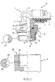
- Figure 1 shows a partial longitudinal section through a sealing system with a sealing ring mounted on a coupling member with a 90° insert and threaded swivel nut for connecting together a pipe and a user device (not shown), the latter having a seat. This is shown in a configuration of disengagement between the coupling member and the seat;
- Figure 2 shows the sealing system with a sealing ring as in Figure 1, in a configuration of assembly of the coupling member in the seat;
- Figure 3 shows a partial longitudinal section through the sealing system groove formed on the swivel nut, the latter having a threaded shank;
- Figure 4 shows in plan view and longitudinal section the sealing ring of the sealing system, in the original configuration prior to assembly of the ring on the groove;
- Figure 5 is a partial longitudinal section through the sealing system with a sealing ring on a coupling member with insert only provided with a threaded shank for connecting together a pipe and a user device (not shown), the latter having a threaded seat. This is shown in the configuration of disengagement of the coupling member from the seat;
- Figure 6 shows the sealing system with a sealing ring as in Figure 5, in a configuration of assembly of the coupling member in the seat.
- the number 1 denotes a coupling member for joining a pipe 2, which is generally of plastic, to a user device (not shown) that has a threaded seat 3.
- the said seat is provided with a thread 28 of the seat 3 and said thread is limited by flanks 28'of the thread 28 of the seat 3.
- the inside of the coupling member 1 is intended to contain a stationary or moving fluid, which may be liquid (oil or water) or gaseous (air), which flows from the pipe 2 to the user device or vice versa.
- a stationary or moving fluid which may be liquid (oil or water) or gaseous (air), which flows from the pipe 2 to the user device or vice versa.
- the coupling member 1 comprises a hollow insert 4 and a swivel nut 5 in which the said insert 4 is mounted, in the configuration of engagement between the insert 4 and the swivel nut 5.
- the insert 4 is connected, towards one end 6, to the pipe 2.
- the connection is made possible by a series of clamping and sealing elements 7 situated in the gap between the pipe 2 and the first end 6 of the insert 4.
- the clamping and sealing elements 7 make it possible to clamp the pipe 2 in the first end 6 of the insert 4, and at the same time prevent fluid leaking out.
- the insert 4 is provided, towards a second end 8, with an external annular projection 16 and a smooth extension 9 of essentially cylindrical shape, wrapped around an axis X-X of the extension.
- the extension 9 is provided with an end portion 10 which, in the configuration of engagement between the insert 4 and the swivel nut 5, is flared to give an essentially frustoconical configuration.
- the end portion 10 of the extension 9 is flared in order to retain the insert 4 and the swivel nut 5 axially. In other words, the flared end portion 10 prevents the insert 4 and the swivel nut 5 from coming apart along the direction of the axis X-X of the extension.
- the swivel nut 5 which is internally hollow (Figure 1 and Figure 3), is essentially cylindrical and is wrapped around an axis Y-Y of the nut which, preferably, in the configuration of engagement between the swivel nut 5 and the insert 4, coincides with the axis X-X of the extension of the insert 4.
- the swivel nut 5 is defined by an inner surface 11 and an outer surface 12 which are suitably shaped.
- the first end 18 of the nut engages with the second end 8 of the insert 4 and the second end 19 of the nut points towards the seat 3 of the user device.
- the inner surface 11 of the swivel nut 5 is formed by a succession of annular reliefs 13 and annular grooves 14 and 14'.
- the smooth extension 9 of the insert 4 is guided in position by the annular projection 13 of the swivel nut 5 and the flared end portion 10 of the smooth extension 9 retains an anchoring ring 15 which anchors it against one of the annular grooves 14 of the swivel nut 5.
- An internal sealing ring 17 is held in position against the annular groove 14' of the swivel nut 5 by the annular projection 16 of the insert 4.
- the anchoring ring 15 prevents the swivel nut 5 from separating from the coupling member 1 because of the flaring of the end portion 10 of the smooth extension 9.
- the inner sealing ring 17 prevents the fluid from leaking out through the gap between the inner surface 13 of the swivel nut 5 and the insert 4.
- the outer surface 12 of the swivel nut 5 has a profile on which a succession of portions can be identified.
- the outer surface 12 of the swivel nut 5 comprises a shank 20 that can be screwed into the seat 3 of the user device by means of its thread 21, limited by flanks 21' of the shank thread.
- the thread on the shank 21 is preferably conical and, in a preferred embodiment, is generated by the envelope of two similar conical profiles, generally a BSPT type profile and an NPTF type profile.
- the outer surface 12 of the swivel nut 5 comprises an annular groove 22.
- the groove 22 is of frustoconical configuration.
- the groove is preferably shaped frustoconically according to the teaching of international standard ISO-UNI 5711-65.
- the groove 22 of the swivel nut 5 is designed to receive an annular seal 23 ( Figure 1 and Figure 4). The latter is designed to be pressed against a wall of the seat 3 of the user device to create the seal.
- the sealing ring 23 is made of plastic or elastoplastic, generally PTFE.
- the sealing ring 23 is of essentially cylindrical shape in an original configuration prior to assembly on the groove 22 ( Figure 4) and, when fitted on the groove 22, assumes a shape adapted to the groove profile ( Figure 1).
- the outer surface 12 of the swivel nut 5 has a gripping portion 24, suitable for being gripped by a tool so that the swivel nut 5 can be screwed onto the seat 3.
- the sealing ring 23 In the original configuration prior to assembly of the sealing ring 23 on the groove 22, the sealing ring 23 is of essentially cylindrical shape. A tool is used to grip the sealing ring and stretch and expand it. The material of which the sealing ring 23 is made expands elastically under the action of the tool.
- the expanded sealing ring 23 can be fitted onto the groove 22 of the swivel nut 5. When released by the tool, the sealing ring 23 exhibits elastic return, and grips the groove 22 tightly. When the sealing ring 23 is fitted on the groove 22, the sealing ring 23 assumes a shape adapted to the profile of the groove 22.
- the sealing ring 23 in the fitted configuration assumes a frustoconical profile.
- the sealing ring 23 comes into contact with an abutting wall 26 of the seat 3, preferably having a flare 27.
- the interference between the abutting wall 26, or the flare 27, of the seat 3, and the sealing ring 23 causes the sealing ring to deform.
- the deformation of the sealing ring 23 is initially elastic. In other words, when the connection between the swivel nut 5 and the seat 3 is relaxed by unscrewing the swivel nut 5, the sealing ring 23 returns to the condition assumed in the configuration of disengagement of the coupling member 1 from the seat 3.
- the coupling member 1 reaches the screwed-on configuration of engagement with the seat 3, in which the sealing ring 23 is deformed plastically by interference with the abutting wall 26 or with the flare 27 of the seat 3.
- one portion 23' of the sealing ring 23 comes between the flanks 28' of the thread 28 of the seat 3.
- the plastic deformation of the sealing ring 23 in the screwed-on configuration of engagement between the coupling member 1 and the seat 3 causes the material of the sealing ring 23 to flow between the flanks 28' of the thread 28 of the seat 3.
- the main advantage of the sealing system according to the present invention lies in the unusually high rate of production of its sealing ring and in the excellent fit of the said sealing ring on the groove.
- a high rate of production of PTFE sealing rings is achieved by turning them on a lathe from cylindrical bars. Lathe-turning of conical sealing rings can only be done with great difficulty.
- the sealing system also has the advantage of preventing leakage of fluid out through the threaded connection between the coupling member and the threaded seat of the user device.
- the coupling member 1 comprises an insert 30 (Figure 5) connected towards the first end 6 to the pipe 2 by means of the series of clamping and sealing elements 7.
- the second end 8 of the insert 30 has a threaded shank 31 which screws into the seat 3 of the user device.
- the insert 30 has the groove 22 in which the annular seal 23 is positionable, in the fitted configuration.
Landscapes
- Engineering & Computer Science (AREA)
- General Engineering & Computer Science (AREA)
- Mechanical Engineering (AREA)
- Joints With Pressure Members (AREA)
- Gasket Seals (AREA)
- Electrical Discharge Machining, Electrochemical Machining, And Combined Machining (AREA)
Abstract
Description
- The present invention relates to a sealing system with a sealing ring which can be used on coupling members for connecting pipes to user devices such as pumps, compressors, tanks and the like, essentially in hydraulic, pneumatic and plumbing settings.
- The connection between a pipe carrying a fluid and a user device is typically effected by a coupling member consisting of a single insert or of an insert with an associated appropriately shaped swivel nut.
- In a connection made with a single insert, one end of the insert is connected to the pipe while the other is provided with a shank that screws into a seat on the user device.
- When making the connection with an insert and a swivel nut, one end of the insert is connected to the pipe while the other end is connected to the swivel nut. In this version of the coupling member, the swivel nut is provided with a threaded shank that screws into the seat on the user device.
- The sealing system, in both the insert-type connection and in the insert with swivel nut-type connection prevents fluid leaking out through the threaded connection formed between the shank of the coupling member and the seat of the user device, especially when the threaded connection is not fluidtight. This is particularly the case when using coupling members with shanks provided with a short thread.
- The current tendency is to use threads characterized by having little length in the direction of the axis of the shank (longitudinal direction). This tendency is due to the increasing use of "universal" threads generated by the envelope of two standard conical profiles (for example, the envelope of a BSPT profile and an NPTF profile, which are much used in hydraulics and pneumatics).
- The "universal" threads are well known to be shorter than normal standard threads. This is to allow generation of the envelope on which they are based.
- The "universal" thread does not produce a fluidtight connection between the flanks of the thread of the shank and those of the thread of the seat. The sealing system therefore assumes a fundamental importance in the functionality of the connection.
- Generally speaking, sealing systems use a sealing ring to act as a physical obstacle to the escape of fluid into the external environment.
- A practical example of a sealing system with a sealing ring for making couplings with a threaded shank used in hydraulic or pneumatic applications is disclosed in United States Patent No. 5,441,314.
- The above patent discloses a sealing system that uses a groove in the vicinity of the threaded shank, at the opposite end to the end of the shank. The groove contains a PTFE (polytetrafluoroethylene) sealing ring that has conical side walls and is shaped so as to fit the walls of the groove.
- It is known, however, that the manufacture and inspection of sealing rings that have conical side walls can present some difficulties, which increases the costs of manufacture.
- High productivity for PTFE sealing rings is ensured by lathe turning, which can only be done with great difficulty to produce conical sealing rings.
- Moreover, to inspect a conical sealing ring, as must be done to ensure stable fitting of the ring in its groove, requires measuring two diameters and one thickness, or one diameter, one length and one cone angle. This greatly increases inspection times.
- There is therefore an awareness of the need to provide high productivity sealing systems with sealing rings which, at the same time, will ensure that the ring is a good fit in its groove.
- The problem addressed by the present invention is that of devising a sealing system with a sealing ring in which the structural and functional characteristics are such as to fulfil the abovementioned needs and at the same time obviate the disadvantages indicated with reference to the prior art.
- The problem is solved by a sealing system with sealing ring for coupling members for connecting pipes to user devices such as pumps, compressors, tanks and the like, by means of a shank that screws into a seat provided on the user device and comprises a groove and an annular seal. The groove is situated in a position adjacent to the shank of the coupling member at the opposite end from the end of the shank, and is able to receive the sealing ring which is designed to be pressed against an abutting wall or flared portion of the seat of the user device in order to establish the seal. The annular seal, in its original configuration prior to assembly, is of an essentially cylindrical shape and, in the configuration of compression of the sealing ring on the groove, assumes a shape adapted to the profile of the groove.
- Further features and the advantages of the sealing system according to the present invention will become clear in the course of the following description of a preferred embodiment thereof given by way of non-restrictive indication with reference to the accompanying figures, in which:
- Figure 1 shows a partial longitudinal section through a sealing system with a sealing ring mounted on a coupling member with a 90° insert and threaded swivel nut for connecting together a pipe and a user device (not shown), the latter having a seat. This is shown in a configuration of disengagement between the coupling member and the seat;
- Figure 2 shows the sealing system with a sealing ring as in Figure 1, in a configuration of assembly of the coupling member in the seat;
- Figure 3 shows a partial longitudinal section through the sealing system groove formed on the swivel nut, the latter having a threaded shank;
- Figure 4 shows in plan view and longitudinal section the sealing ring of the sealing system, in the original configuration prior to assembly of the ring on the groove;
- Figure 5 is a partial longitudinal section through the sealing system with a sealing ring on a coupling member with insert only provided with a threaded shank for connecting together a pipe and a user device (not shown), the latter having a threaded seat. This is shown in the configuration of disengagement of the coupling member from the seat; and
- Figure 6 shows the sealing system with a sealing ring as in Figure 5, in a configuration of assembly of the coupling member in the seat.
- With reference to Figure 1, the
number 1 denotes a coupling member for joining apipe 2, which is generally of plastic, to a user device (not shown) that has a threadedseat 3. The said seat is provided with athread 28 of theseat 3 and said thread is limited by flanks 28'of thethread 28 of theseat 3. - The inside of the
coupling member 1 is intended to contain a stationary or moving fluid, which may be liquid (oil or water) or gaseous (air), which flows from thepipe 2 to the user device or vice versa. - The
coupling member 1 comprises ahollow insert 4 and aswivel nut 5 in which the saidinsert 4 is mounted, in the configuration of engagement between theinsert 4 and theswivel nut 5. - The
insert 4 is connected, towards oneend 6, to thepipe 2. The connection is made possible by a series of clamping and sealingelements 7 situated in the gap between thepipe 2 and thefirst end 6 of theinsert 4. - The clamping and
sealing elements 7 make it possible to clamp thepipe 2 in thefirst end 6 of theinsert 4, and at the same time prevent fluid leaking out. - The
insert 4 is provided, towards asecond end 8, with an externalannular projection 16 and a smooth extension 9 of essentially cylindrical shape, wrapped around an axis X-X of the extension. - The extension 9 is provided with an
end portion 10 which, in the configuration of engagement between theinsert 4 and theswivel nut 5, is flared to give an essentially frustoconical configuration. Theend portion 10 of the extension 9 is flared in order to retain theinsert 4 and theswivel nut 5 axially. In other words, theflared end portion 10 prevents theinsert 4 and theswivel nut 5 from coming apart along the direction of the axis X-X of the extension. - The
swivel nut 5, which is internally hollow (Figure 1 and Figure 3), is essentially cylindrical and is wrapped around an axis Y-Y of the nut which, preferably, in the configuration of engagement between theswivel nut 5 and theinsert 4, coincides with the axis X-X of the extension of theinsert 4. - The
swivel nut 5 is defined by aninner surface 11 and anouter surface 12 which are suitably shaped. Thefirst end 18 of the nut engages with thesecond end 8 of theinsert 4 and thesecond end 19 of the nut points towards theseat 3 of the user device. - The
inner surface 11 of theswivel nut 5 is formed by a succession ofannular reliefs 13 andannular grooves 14 and 14'. - In the configuration of engagement between the
insert 4 and theswivel nut 5, the smooth extension 9 of theinsert 4 is guided in position by theannular projection 13 of theswivel nut 5 and theflared end portion 10 of the smooth extension 9 retains ananchoring ring 15 which anchors it against one of theannular grooves 14 of theswivel nut 5. Aninternal sealing ring 17 is held in position against the annular groove 14' of theswivel nut 5 by theannular projection 16 of theinsert 4. - The anchoring
ring 15 prevents theswivel nut 5 from separating from thecoupling member 1 because of the flaring of theend portion 10 of the smooth extension 9. - The
inner sealing ring 17 prevents the fluid from leaking out through the gap between theinner surface 13 of theswivel nut 5 and theinsert 4. - The
outer surface 12 of theswivel nut 5 has a profile on which a succession of portions can be identified. - Towards the
second end 19 of the nut, theouter surface 12 of theswivel nut 5 comprises ashank 20 that can be screwed into theseat 3 of the user device by means of itsthread 21, limited by flanks 21' of the shank thread. - The thread on the
shank 21 is preferably conical and, in a preferred embodiment, is generated by the envelope of two similar conical profiles, generally a BSPT type profile and an NPTF type profile. - Next to the
shank 20, at the opposite end from the end of the shank, theouter surface 12 of theswivel nut 5 comprises anannular groove 22. - In a preferred embodiment of the sealing system, the
groove 22 is of frustoconical configuration. The groove is preferably shaped frustoconically according to the teaching of international standard ISO-UNI 5711-65. - The
groove 22 of theswivel nut 5 is designed to receive an annular seal 23 (Figure 1 and Figure 4). The latter is designed to be pressed against a wall of theseat 3 of the user device to create the seal. - In a preferred embodiment of the sealing system, the sealing
ring 23 is made of plastic or elastoplastic, generally PTFE. - The
sealing ring 23 is of essentially cylindrical shape in an original configuration prior to assembly on the groove 22 (Figure 4) and, when fitted on thegroove 22, assumes a shape adapted to the groove profile (Figure 1). - Towards the
first end 18 of the nut 5 (Figure 3), theouter surface 12 of theswivel nut 5 has a grippingportion 24, suitable for being gripped by a tool so that theswivel nut 5 can be screwed onto theseat 3. - In the original configuration prior to assembly of the sealing
ring 23 on thegroove 22, the sealingring 23 is of essentially cylindrical shape. A tool is used to grip the sealing ring and stretch and expand it. The material of which the sealingring 23 is made expands elastically under the action of the tool. - The expanded
sealing ring 23 can be fitted onto thegroove 22 of theswivel nut 5. When released by the tool, the sealingring 23 exhibits elastic return, and grips thegroove 22 tightly. When the sealingring 23 is fitted on thegroove 22, the sealingring 23 assumes a shape adapted to the profile of thegroove 22. - As a matter of preference, by giving the groove 22 a frustoconical profile, the sealing
ring 23 in the fitted configuration assumes a frustoconical profile. - By gripping the
swivel nut 5, it is possible to screw theshank 20 of theswivel nut 5 onto theseat 3 of the user device, taking thecoupling member 1 from a configuration of disengagement from theseat 3 to a screwed-on configuration of engagement (Figure 2). - As the
swivel nut 5 is screwed into theseat 3, the sealingring 23 comes into contact with an abuttingwall 26 of theseat 3, preferably having aflare 27. The interference between the abuttingwall 26, or theflare 27, of theseat 3, and the sealingring 23 causes the sealing ring to deform. - The deformation of the sealing
ring 23 is initially elastic. In other words, when the connection between theswivel nut 5 and theseat 3 is relaxed by unscrewing theswivel nut 5, the sealingring 23 returns to the condition assumed in the configuration of disengagement of thecoupling member 1 from theseat 3. - As the
swivel nut 5 continues to be screwed into theseat 3, thecoupling member 1 reaches the screwed-on configuration of engagement with theseat 3, in which the sealingring 23 is deformed plastically by interference with the abuttingwall 26 or with theflare 27 of theseat 3. In the screwed-on configuration of engagement of the coupling member with theseat 3, one portion 23' of the sealingring 23 comes between the flanks 28' of thethread 28 of theseat 3. - In other words, the plastic deformation of the sealing
ring 23 in the screwed-on configuration of engagement between thecoupling member 1 and theseat 3 causes the material of the sealingring 23 to flow between the flanks 28' of thethread 28 of theseat 3. - The main advantage of the sealing system according to the present invention lies in the unusually high rate of production of its sealing ring and in the excellent fit of the said sealing ring on the groove.
- A high rate of production of PTFE sealing rings is achieved by turning them on a lathe from cylindrical bars. Lathe-turning of conical sealing rings can only be done with great difficulty.
- The sealing system also has the advantage of preventing leakage of fluid out through the threaded connection between the coupling member and the threaded seat of the user device.
- A variant of the same invention is shown in Figure 5 and in Figure 6, where parts structurally and functionally identical to those of the sealing system shown in Figures 1, 2, 3 and 4 keep the same reference numbers and are not described below.
- The
coupling member 1 comprises an insert 30 (Figure 5) connected towards thefirst end 6 to thepipe 2 by means of the series of clamping and sealingelements 7. Thesecond end 8 of theinsert 30 has a threadedshank 31 which screws into theseat 3 of the user device. - Next to the threaded
shank 31, at the opposite end from the shank end, theinsert 30 has thegroove 22 in which theannular seal 23 is positionable, in the fitted configuration. - In the screwed-on configuration of engagement between the
coupling member 1 and the seat 3 (Figure 6), theinsert 30 is screwed into the threaded seat of the user device. - Clearly, in order to meet contingent and specific requirements, a person skilled in the art could make numerous modifications and alterations that would all be contained in the scope of protection of the invention as defined by the following claims, to the sealing system with sealing ring as described above and explained with reference to the figures.
Claims (11)
- Sealing system with sealing ring for coupling members (1) for connecting pipes to user devices such as pumps, compressors, tanks and the like, by means of a shank (21, 31) that screws into a seat (3) provided on the said user device, comprising a groove (22) situated in a position adjacent to the shank (21, 31) of the coupling member (1), at the opposite end from the end of the shank (21, 31), the said groove (22) being able to receive an annular seal (23) designed to be pressed against an abutting wall (26) of the said seat (3) of the user device in order to establish the seal, the said sealing system being characterized in that the sealing ring (23), in its original configuration prior to assembly, is of an essentially cylindrical shape and, in the configuration of compression of the sealing ring (23) on the groove (22), assumes a shape adapted to the profile of the groove (22).
- Sealing system according to Claim 1, in which the groove (22) is of an essentially frustoconical configuration.
- Sealing system according to Claim 2, in which the groove (22) is essentially configured according to international standard ISO-UNI 5711-65.
- Sealing system according to Claim 2 or Claim 3, in which the sealing ring (23), in the configuration of compression on the groove (22), assumes an essentially frustoconical shape.
- Sealing system according to one of Claims 1 to 4, in which the shank (21, 31) is provided with a "universal" thread generated by the envelope of similar thread profiles.
- Sealing system according to Claim 5, in which the "universal" thread of the shank (21, 31) is generated by the envelope of two conical thread profiles.
- Sealing system according to one of Claims 1 to 6, in which the sealing ring (23) is made of an elastoplastic material.
- Sealing system according to Claim 7, in which the sealing ring (23) is made of polytetrafluoroethylene (PTFE).
- Sealing system according to one of Claims 1 to 8, in which the sealing ring (23) in the configuration of engagement between the coupling member (1) and the seat (3) deforms plastically by the interference with the abutting wall (26) of the seat (3).
- Sealing system according to Claim 9, in which a portion (23') of the sealing ring (23), in the screwed configuration of engagement between the coupling member (1) and the seat (3), flows between flanks (28') of the thread of the seat.
- Sealing system according to one of Claims 1 to 10, in which the abutting wall (26) is flared (27) to promote contact between the sealing ring (23) and the seat (3) of the user device.
Priority Applications (4)
| Application Number | Priority Date | Filing Date | Title |
|---|---|---|---|
| DE60108737T DE60108737T2 (en) | 2001-07-24 | 2001-07-24 | Sealing system with sealing ring |
| AT01830493T ATE288559T1 (en) | 2001-07-24 | 2001-07-24 | SEALING SYSTEM WITH SEALING RING |
| EP01830493A EP1279880B1 (en) | 2001-07-24 | 2001-07-24 | Sealing system with sealing ring |
| US09/983,841 US7588253B2 (en) | 2001-07-24 | 2001-10-26 | Sealing system with sealing ring |
Applications Claiming Priority (1)
| Application Number | Priority Date | Filing Date | Title |
|---|---|---|---|
| EP01830493A EP1279880B1 (en) | 2001-07-24 | 2001-07-24 | Sealing system with sealing ring |
Publications (2)
| Publication Number | Publication Date |
|---|---|
| EP1279880A1 true EP1279880A1 (en) | 2003-01-29 |
| EP1279880B1 EP1279880B1 (en) | 2005-02-02 |
Family
ID=8184629
Family Applications (1)
| Application Number | Title | Priority Date | Filing Date |
|---|---|---|---|
| EP01830493A Expired - Lifetime EP1279880B1 (en) | 2001-07-24 | 2001-07-24 | Sealing system with sealing ring |
Country Status (4)
| Country | Link |
|---|---|
| US (1) | US7588253B2 (en) |
| EP (1) | EP1279880B1 (en) |
| AT (1) | ATE288559T1 (en) |
| DE (1) | DE60108737T2 (en) |
Cited By (3)
| Publication number | Priority date | Publication date | Assignee | Title |
|---|---|---|---|---|
| JP2010185568A (en) * | 2009-01-14 | 2010-08-26 | Smc Corp | Pipe joint |
| CN101963260A (en) * | 2010-10-20 | 2011-02-02 | 杭州联通管业有限公司 | Reinforced flaring-type winding-structure wall pipe |
| WO2024120690A1 (en) * | 2022-12-08 | 2024-06-13 | Robert Bosch Gmbh | Functional unit for a gas system of a mobile application or a stationary application, and gas system for a mobile application or a stationary application |
Families Citing this family (6)
| Publication number | Priority date | Publication date | Assignee | Title |
|---|---|---|---|---|
| US20080258398A1 (en) * | 2007-03-30 | 2008-10-23 | Whitlow Mark S | Seal |
| DE102010000715A1 (en) * | 2010-01-07 | 2011-07-14 | Robert Bosch GmbH, 70469 | Fixing a stop washer |
| US8967731B2 (en) * | 2011-02-23 | 2015-03-03 | Shimano Inc. | Spoke attachment structure |
| US10139133B2 (en) * | 2015-12-03 | 2018-11-27 | Heateflex Corporation | In-line heater |
| US10815988B2 (en) * | 2017-04-18 | 2020-10-27 | St9 Gas And Oil, Llc | Frac pump sealed nut assembly |
| US10711876B1 (en) * | 2019-10-28 | 2020-07-14 | Saptfc Holding, Llc | Reinforcement sealing tubes for stabilizing a housing in an automobile transmission |
Citations (3)
| Publication number | Priority date | Publication date | Assignee | Title |
|---|---|---|---|---|
| US3255916A (en) * | 1964-01-27 | 1966-06-14 | New York Air Brake Co | Static seal |
| DE4217154A1 (en) * | 1992-05-23 | 1993-09-23 | Globus Gummiwerke Gmbh | Radial sealing arrangement - has diverging mounting surfaces formed from groove base and which are convex, relative to seal which is wedge shaped when not in groove |
| US5441314A (en) | 1994-07-01 | 1995-08-15 | Giovanni; Camozzi | Threaded fittings |
Family Cites Families (28)
| Publication number | Priority date | Publication date | Assignee | Title |
|---|---|---|---|---|
| US2110825A (en) * | 1935-03-12 | 1938-03-08 | Nat Supply Co | Packed tool joint |
| US2252496A (en) * | 1940-03-13 | 1941-08-12 | Defiance Spark Plugs Inc | Spark plug and method of making |
| US2343235A (en) * | 1941-11-28 | 1944-02-29 | Weatherhead Co | Universal pipe fitting |
| US2381829A (en) * | 1943-06-18 | 1945-08-07 | Cons Vultee Aircraft Corp | Tube coupling |
| US3164890A (en) * | 1956-05-31 | 1965-01-12 | Parker Hannifin Corp | Method of and tools for assembly of a packing retainer on a threaded coupling member |
| US2924876A (en) * | 1956-12-03 | 1960-02-16 | James E Lewis | Thread lubricant package and method |
| US2995057A (en) * | 1957-03-15 | 1961-08-08 | Parker Hannifin Corp | Seal for rigid seating members wherein protruding portion thereof is receivable into adjacent channel portion |
| US3003795A (en) * | 1959-08-12 | 1961-10-10 | L & L Mfg Company | Tube coupling having a resilient metal sealing sleeve |
| US3275348A (en) * | 1963-05-28 | 1966-09-27 | Vsi Corp | High pressure sealed connections |
| US3779462A (en) * | 1972-02-14 | 1973-12-18 | Nelson Irrigation Corp | Step-by-step rotary sprinkler head with quick-change and color-coded nozzle insert |
| US3747960A (en) * | 1972-05-15 | 1973-07-24 | Thomas & Betts Corp | Coupling |
| US3933358A (en) * | 1974-11-07 | 1976-01-20 | Deere & Company | O-Ring port contour sheath and seal |
| US4033615A (en) | 1975-06-16 | 1977-07-05 | Ross Operating Valve Company | Port thread |
| US4150836A (en) * | 1977-02-16 | 1979-04-24 | Mcdonnell Douglas Corporation | Backed boss seal fitting |
| US4550937A (en) * | 1978-02-27 | 1985-11-05 | Vallourec S.A. | Joint for steel tubes |
| CH640617A5 (en) * | 1979-07-06 | 1984-01-13 | Baumgartner Merzia | CONNECTING ELEMENT FOR SCREWING INTO A LINE OR INTO A APPARATUS FOR CONNECTION TO THE LINE SYSTEM OF THE PRESSURE MEDIUM CIRCUIT. |
| US4280721A (en) * | 1979-11-14 | 1981-07-28 | United Technologies Corporation | Angularly lockable fitting |
| DE3203857C2 (en) * | 1982-02-03 | 1984-08-02 | Mannesmann AG, 4000 Düsseldorf | Oil field pipe connection and method of connecting oil field pipes |
| DE3308043C1 (en) * | 1983-03-07 | 1984-08-16 | Daimler-Benz Ag, 7000 Stuttgart | Sealing ring arrangement on a screw cap |
| US4688832A (en) * | 1984-08-13 | 1987-08-25 | Hydril Company | Well pipe joint |
| US4705307A (en) * | 1984-09-21 | 1987-11-10 | James B. N. Morris | Tubular goods joint |
| US4934742A (en) * | 1988-01-27 | 1990-06-19 | Nwd International, Inc. | Hydraulic coupling |
| JPH0686916B2 (en) | 1988-11-01 | 1994-11-02 | エスエムシー株式会社 | Pipe fitting |
| JPH0648075B2 (en) * | 1990-04-16 | 1994-06-22 | エスエムシー株式会社 | Pipe fitting |
| DE4111463A1 (en) | 1991-04-09 | 1992-10-15 | Festo Kg | EXTERNAL THREAD AND INTERNAL THREAD, PREFERABLY FOR THE PRODUCTION OF FLUIDIC CONNECTIONS IN PNEUMATICS |
| FR2733021B1 (en) * | 1995-04-13 | 1997-06-06 | Joint Francais | JOINT AND ASSEMBLY METHOD |
| WO1999008034A1 (en) * | 1997-08-11 | 1999-02-18 | Marubeni Tubulars, Inc. | Tubular connection |
| US6325389B1 (en) * | 1999-10-25 | 2001-12-04 | Amir Sharify | Self sealing fluid duct/fitting connector |
-
2001
- 2001-07-24 AT AT01830493T patent/ATE288559T1/en not_active IP Right Cessation
- 2001-07-24 EP EP01830493A patent/EP1279880B1/en not_active Expired - Lifetime
- 2001-07-24 DE DE60108737T patent/DE60108737T2/en not_active Expired - Fee Related
- 2001-10-26 US US09/983,841 patent/US7588253B2/en not_active Expired - Lifetime
Patent Citations (3)
| Publication number | Priority date | Publication date | Assignee | Title |
|---|---|---|---|---|
| US3255916A (en) * | 1964-01-27 | 1966-06-14 | New York Air Brake Co | Static seal |
| DE4217154A1 (en) * | 1992-05-23 | 1993-09-23 | Globus Gummiwerke Gmbh | Radial sealing arrangement - has diverging mounting surfaces formed from groove base and which are convex, relative to seal which is wedge shaped when not in groove |
| US5441314A (en) | 1994-07-01 | 1995-08-15 | Giovanni; Camozzi | Threaded fittings |
Cited By (6)
| Publication number | Priority date | Publication date | Assignee | Title |
|---|---|---|---|---|
| JP2010185568A (en) * | 2009-01-14 | 2010-08-26 | Smc Corp | Pipe joint |
| EP2378176A1 (en) * | 2009-01-14 | 2011-10-19 | SMC Kabushiki Kaisha | Pipe joint |
| EP2378176A4 (en) * | 2009-01-14 | 2013-08-07 | Smc Kk | Pipe joint |
| US9885439B2 (en) | 2009-01-14 | 2018-02-06 | Smc Kabushiki Kaisha | Pipe joint |
| CN101963260A (en) * | 2010-10-20 | 2011-02-02 | 杭州联通管业有限公司 | Reinforced flaring-type winding-structure wall pipe |
| WO2024120690A1 (en) * | 2022-12-08 | 2024-06-13 | Robert Bosch Gmbh | Functional unit for a gas system of a mobile application or a stationary application, and gas system for a mobile application or a stationary application |
Also Published As
| Publication number | Publication date |
|---|---|
| US20030030231A1 (en) | 2003-02-13 |
| ATE288559T1 (en) | 2005-02-15 |
| DE60108737T2 (en) | 2006-03-30 |
| EP1279880B1 (en) | 2005-02-02 |
| DE60108737D1 (en) | 2005-03-10 |
| US7588253B2 (en) | 2009-09-15 |
Similar Documents
| Publication | Publication Date | Title |
|---|---|---|
| US4252346A (en) | Connection for transition from a cutting ring joint or similar to a flange joint | |
| US6089621A (en) | Pipe joint made of resin | |
| US6598908B1 (en) | Hydraulic fitting | |
| US7469936B2 (en) | Pipe coupling | |
| EP2995839B1 (en) | Pipe connecting device | |
| EP2995840B1 (en) | Pipe connecting device | |
| US4807911A (en) | Push in fitting converter for plastic tubing | |
| US4691944A (en) | Tubing connector | |
| JPH02278094A (en) | Cantilever lip conduit coupling member and assembly thereof | |
| US4805944A (en) | Beaded tube coupling with end seal ring | |
| US5110160A (en) | High pressure port fitting system | |
| EP1279880B1 (en) | Sealing system with sealing ring | |
| EP1144892B1 (en) | Pipe fitting element, particularly for plastic pipes | |
| US6702258B1 (en) | Universal ball valve assembly | |
| US20060163872A1 (en) | Pipe coupling | |
| WO2004027305A1 (en) | Integral end connection for tube fitting | |
| EP1543266B1 (en) | Fluid quick connector for threaded fluid components | |
| CN213576133U (en) | Three-way joint | |
| CN2314211Y (en) | Push-pressing holder self locking quick joint | |
| JP2010101431A (en) | Tube fitting | |
| KR970028028A (en) | Tube joint | |
| CN213745456U (en) | Elbow joint | |
| GB2113788A (en) | Pipe couplings | |
| RU205462U1 (en) | ADAPTER FITTING | |
| CN2179519Y (en) | Low pressure flexible pipe joint |
Legal Events
| Date | Code | Title | Description |
|---|---|---|---|
| PUAI | Public reference made under article 153(3) epc to a published international application that has entered the european phase |
Free format text: ORIGINAL CODE: 0009012 |
|
| 17P | Request for examination filed |
Effective date: 20020717 |
|
| AK | Designated contracting states |
Designated state(s): AT BE CH CY DE DK ES FI FR GB GR IE IT LI LU MC NL PT SE TR |
|
| AX | Request for extension of the european patent |
Extension state: AL LT LV MK RO SI |
|
| AKX | Designation fees paid |
Designated state(s): AT BE CH CY DE DK ES FI FR GB GR IE IT LI LU MC NL PT SE TR |
|
| 17Q | First examination report despatched |
Effective date: 20031203 |
|
| GRAP | Despatch of communication of intention to grant a patent |
Free format text: ORIGINAL CODE: EPIDOSNIGR1 |
|
| GRAS | Grant fee paid |
Free format text: ORIGINAL CODE: EPIDOSNIGR3 |
|
| GRAA | (expected) grant |
Free format text: ORIGINAL CODE: 0009210 |
|
| AK | Designated contracting states |
Kind code of ref document: B1 Designated state(s): AT BE CH CY DE DK ES FI FR GB GR IE IT LI LU MC NL PT SE TR |
|
| PG25 | Lapsed in a contracting state [announced via postgrant information from national office to epo] |
Ref country code: LI Free format text: LAPSE BECAUSE OF FAILURE TO SUBMIT A TRANSLATION OF THE DESCRIPTION OR TO PAY THE FEE WITHIN THE PRESCRIBED TIME-LIMIT Effective date: 20050202 Ref country code: TR Free format text: LAPSE BECAUSE OF FAILURE TO SUBMIT A TRANSLATION OF THE DESCRIPTION OR TO PAY THE FEE WITHIN THE PRESCRIBED TIME-LIMIT Effective date: 20050202 Ref country code: NL Free format text: LAPSE BECAUSE OF FAILURE TO SUBMIT A TRANSLATION OF THE DESCRIPTION OR TO PAY THE FEE WITHIN THE PRESCRIBED TIME-LIMIT Effective date: 20050202 Ref country code: AT Free format text: LAPSE BECAUSE OF FAILURE TO SUBMIT A TRANSLATION OF THE DESCRIPTION OR TO PAY THE FEE WITHIN THE PRESCRIBED TIME-LIMIT Effective date: 20050202 Ref country code: CH Free format text: LAPSE BECAUSE OF FAILURE TO SUBMIT A TRANSLATION OF THE DESCRIPTION OR TO PAY THE FEE WITHIN THE PRESCRIBED TIME-LIMIT Effective date: 20050202 Ref country code: BE Free format text: LAPSE BECAUSE OF FAILURE TO SUBMIT A TRANSLATION OF THE DESCRIPTION OR TO PAY THE FEE WITHIN THE PRESCRIBED TIME-LIMIT Effective date: 20050202 Ref country code: FI Free format text: LAPSE BECAUSE OF FAILURE TO SUBMIT A TRANSLATION OF THE DESCRIPTION OR TO PAY THE FEE WITHIN THE PRESCRIBED TIME-LIMIT Effective date: 20050202 Ref country code: ES Free format text: LAPSE BECAUSE OF FAILURE TO SUBMIT A TRANSLATION OF THE DESCRIPTION OR TO PAY THE FEE WITHIN THE PRESCRIBED TIME-LIMIT Effective date: 20050202 |
|
| REG | Reference to a national code |
Ref country code: GB Ref legal event code: FG4D |
|
| REG | Reference to a national code |
Ref country code: CH Ref legal event code: EP |
|
| REG | Reference to a national code |
Ref country code: IE Ref legal event code: FG4D |
|
| REF | Corresponds to: |
Ref document number: 60108737 Country of ref document: DE Date of ref document: 20050310 Kind code of ref document: P |
|
| PG25 | Lapsed in a contracting state [announced via postgrant information from national office to epo] |
Ref country code: GR Free format text: LAPSE BECAUSE OF FAILURE TO SUBMIT A TRANSLATION OF THE DESCRIPTION OR TO PAY THE FEE WITHIN THE PRESCRIBED TIME-LIMIT Effective date: 20050502 Ref country code: DK Free format text: LAPSE BECAUSE OF FAILURE TO SUBMIT A TRANSLATION OF THE DESCRIPTION OR TO PAY THE FEE WITHIN THE PRESCRIBED TIME-LIMIT Effective date: 20050502 Ref country code: SE Free format text: LAPSE BECAUSE OF FAILURE TO SUBMIT A TRANSLATION OF THE DESCRIPTION OR TO PAY THE FEE WITHIN THE PRESCRIBED TIME-LIMIT Effective date: 20050502 |
|
| PG25 | Lapsed in a contracting state [announced via postgrant information from national office to epo] |
Ref country code: LU Free format text: LAPSE BECAUSE OF NON-PAYMENT OF DUE FEES Effective date: 20050724 Ref country code: CY Free format text: LAPSE BECAUSE OF FAILURE TO SUBMIT A TRANSLATION OF THE DESCRIPTION OR TO PAY THE FEE WITHIN THE PRESCRIBED TIME-LIMIT Effective date: 20050724 Ref country code: GB Free format text: LAPSE BECAUSE OF NON-PAYMENT OF DUE FEES Effective date: 20050724 |
|
| PG25 | Lapsed in a contracting state [announced via postgrant information from national office to epo] |
Ref country code: IE Free format text: LAPSE BECAUSE OF NON-PAYMENT OF DUE FEES Effective date: 20050725 |
|
| PG25 | Lapsed in a contracting state [announced via postgrant information from national office to epo] |
Ref country code: MC Free format text: LAPSE BECAUSE OF NON-PAYMENT OF DUE FEES Effective date: 20050731 |
|
| NLV1 | Nl: lapsed or annulled due to failure to fulfill the requirements of art. 29p and 29m of the patents act | ||
| REG | Reference to a national code |
Ref country code: CH Ref legal event code: PL |
|
| ET | Fr: translation filed | ||
| PLBE | No opposition filed within time limit |
Free format text: ORIGINAL CODE: 0009261 |
|
| STAA | Information on the status of an ep patent application or granted ep patent |
Free format text: STATUS: NO OPPOSITION FILED WITHIN TIME LIMIT |
|
| 26N | No opposition filed |
Effective date: 20051103 |
|
| GBPC | Gb: european patent ceased through non-payment of renewal fee |
Effective date: 20050724 |
|
| REG | Reference to a national code |
Ref country code: IE Ref legal event code: MM4A |
|
| PG25 | Lapsed in a contracting state [announced via postgrant information from national office to epo] |
Ref country code: PT Free format text: LAPSE BECAUSE OF NON-PAYMENT OF DUE FEES Effective date: 20050702 |
|
| PGFP | Annual fee paid to national office [announced via postgrant information from national office to epo] |
Ref country code: DE Payment date: 20080623 Year of fee payment: 8 |
|
| PG25 | Lapsed in a contracting state [announced via postgrant information from national office to epo] |
Ref country code: DE Free format text: LAPSE BECAUSE OF NON-PAYMENT OF DUE FEES Effective date: 20100202 |
|
| REG | Reference to a national code |
Ref country code: FR Ref legal event code: PLFP Year of fee payment: 16 |
|
| REG | Reference to a national code |
Ref country code: FR Ref legal event code: PLFP Year of fee payment: 17 |
|
| REG | Reference to a national code |
Ref country code: FR Ref legal event code: PLFP Year of fee payment: 18 |
|
| PGFP | Annual fee paid to national office [announced via postgrant information from national office to epo] |
Ref country code: FR Payment date: 20200730 Year of fee payment: 20 |
|
| PGFP | Annual fee paid to national office [announced via postgrant information from national office to epo] |
Ref country code: IT Payment date: 20200707 Year of fee payment: 20 |