EP1279857A2 - Floating rod guide for monotube strut - Google Patents
Floating rod guide for monotube strut Download PDFInfo
- Publication number
- EP1279857A2 EP1279857A2 EP02077795A EP02077795A EP1279857A2 EP 1279857 A2 EP1279857 A2 EP 1279857A2 EP 02077795 A EP02077795 A EP 02077795A EP 02077795 A EP02077795 A EP 02077795A EP 1279857 A2 EP1279857 A2 EP 1279857A2
- Authority
- EP
- European Patent Office
- Prior art keywords
- rod
- seal cover
- guide
- rod guide
- strut
- Prior art date
- Legal status (The legal status is an assumption and is not a legal conclusion. Google has not performed a legal analysis and makes no representation as to the accuracy of the status listed.)
- Withdrawn
Links
- 239000004519 grease Substances 0.000 claims description 9
- PXHVJJICTQNCMI-UHFFFAOYSA-N Nickel Chemical compound [Ni] PXHVJJICTQNCMI-UHFFFAOYSA-N 0.000 claims description 6
- 229910000831 Steel Inorganic materials 0.000 claims description 5
- 239000010959 steel Substances 0.000 claims description 5
- 238000007747 plating Methods 0.000 claims description 4
- XAGFODPZIPBFFR-UHFFFAOYSA-N aluminium Chemical compound [Al] XAGFODPZIPBFFR-UHFFFAOYSA-N 0.000 claims description 3
- 229910052782 aluminium Inorganic materials 0.000 claims description 3
- 229910052759 nickel Inorganic materials 0.000 claims description 3
- 239000011248 coating agent Substances 0.000 claims 3
- 238000000576 coating method Methods 0.000 claims 3
- 239000012530 fluid Substances 0.000 description 19
- XEEYBQQBJWHFJM-UHFFFAOYSA-N Iron Chemical compound [Fe] XEEYBQQBJWHFJM-UHFFFAOYSA-N 0.000 description 6
- 239000007789 gas Substances 0.000 description 6
- 239000000725 suspension Substances 0.000 description 6
- 230000006835 compression Effects 0.000 description 5
- 238000007906 compression Methods 0.000 description 5
- 230000008901 benefit Effects 0.000 description 4
- 239000003921 oil Substances 0.000 description 4
- 239000002245 particle Substances 0.000 description 4
- 238000013016 damping Methods 0.000 description 3
- 229910052742 iron Inorganic materials 0.000 description 3
- 230000007246 mechanism Effects 0.000 description 3
- 230000002028 premature Effects 0.000 description 3
- 238000003466 welding Methods 0.000 description 3
- 230000000712 assembly Effects 0.000 description 2
- 238000000429 assembly Methods 0.000 description 2
- 230000008859 change Effects 0.000 description 2
- 239000000463 material Substances 0.000 description 2
- 230000004048 modification Effects 0.000 description 2
- 238000012986 modification Methods 0.000 description 2
- IJGRMHOSHXDMSA-UHFFFAOYSA-N Atomic nitrogen Chemical compound N#N IJGRMHOSHXDMSA-UHFFFAOYSA-N 0.000 description 1
- 239000004215 Carbon black (E152) Substances 0.000 description 1
- 239000004809 Teflon Substances 0.000 description 1
- 229920006362 Teflon® Polymers 0.000 description 1
- 238000005452 bending Methods 0.000 description 1
- 230000007797 corrosion Effects 0.000 description 1
- 238000005260 corrosion Methods 0.000 description 1
- 230000003247 decreasing effect Effects 0.000 description 1
- 229910001873 dinitrogen Inorganic materials 0.000 description 1
- 239000002783 friction material Substances 0.000 description 1
- 239000010720 hydraulic oil Substances 0.000 description 1
- 229930195733 hydrocarbon Natural products 0.000 description 1
- 150000002430 hydrocarbons Chemical class 0.000 description 1
- 239000007788 liquid Substances 0.000 description 1
- 239000000314 lubricant Substances 0.000 description 1
- 238000004519 manufacturing process Methods 0.000 description 1
- 239000003208 petroleum Substances 0.000 description 1
- -1 polytetrafluoroethylene Polymers 0.000 description 1
- 229920001343 polytetrafluoroethylene Polymers 0.000 description 1
- 239000004810 polytetrafluoroethylene Substances 0.000 description 1
- 230000036316 preload Effects 0.000 description 1
- 230000001737 promoting effect Effects 0.000 description 1
- 230000004044 response Effects 0.000 description 1
- 238000000518 rheometry Methods 0.000 description 1
- 238000007789 sealing Methods 0.000 description 1
- 238000000926 separation method Methods 0.000 description 1
- 230000035939 shock Effects 0.000 description 1
- 230000003068 static effect Effects 0.000 description 1
- 230000008719 thickening Effects 0.000 description 1
Images

Classifications
-
- B—PERFORMING OPERATIONS; TRANSPORTING
- B60—VEHICLES IN GENERAL
- B60G—VEHICLE SUSPENSION ARRANGEMENTS
- B60G15/00—Resilient suspensions characterised by arrangement, location or type of combined spring and vibration damper, e.g. telescopic type
- B60G15/02—Resilient suspensions characterised by arrangement, location or type of combined spring and vibration damper, e.g. telescopic type having mechanical spring
- B60G15/06—Resilient suspensions characterised by arrangement, location or type of combined spring and vibration damper, e.g. telescopic type having mechanical spring and fluid damper
- B60G15/07—Resilient suspensions characterised by arrangement, location or type of combined spring and vibration damper, e.g. telescopic type having mechanical spring and fluid damper the damper being connected to the stub axle and the spring being arranged around the damper
-
- B—PERFORMING OPERATIONS; TRANSPORTING
- B60—VEHICLES IN GENERAL
- B60G—VEHICLE SUSPENSION ARRANGEMENTS
- B60G13/00—Resilient suspensions characterised by arrangement, location or type of vibration dampers
- B60G13/001—Arrangements for attachment of dampers
- B60G13/005—Arrangements for attachment of dampers characterised by the mounting on the axle or suspension arm of the damper unit
- B60G13/008—Arrangements for attachment of dampers characterised by the mounting on the axle or suspension arm of the damper unit involving use of an auxiliary cylinder
-
- F—MECHANICAL ENGINEERING; LIGHTING; HEATING; WEAPONS; BLASTING
- F16—ENGINEERING ELEMENTS AND UNITS; GENERAL MEASURES FOR PRODUCING AND MAINTAINING EFFECTIVE FUNCTIONING OF MACHINES OR INSTALLATIONS; THERMAL INSULATION IN GENERAL
- F16F—SPRINGS; SHOCK-ABSORBERS; MEANS FOR DAMPING VIBRATION
- F16F9/00—Springs, vibration-dampers, shock-absorbers, or similarly-constructed movement-dampers using a fluid or the equivalent as damping medium
- F16F9/32—Details
- F16F9/36—Special sealings, including sealings or guides for piston-rods
- F16F9/362—Combination of sealing and guide arrangements for piston rods
-
- F—MECHANICAL ENGINEERING; LIGHTING; HEATING; WEAPONS; BLASTING
- F16—ENGINEERING ELEMENTS AND UNITS; GENERAL MEASURES FOR PRODUCING AND MAINTAINING EFFECTIVE FUNCTIONING OF MACHINES OR INSTALLATIONS; THERMAL INSULATION IN GENERAL
- F16F—SPRINGS; SHOCK-ABSORBERS; MEANS FOR DAMPING VIBRATION
- F16F9/00—Springs, vibration-dampers, shock-absorbers, or similarly-constructed movement-dampers using a fluid or the equivalent as damping medium
- F16F9/32—Details
- F16F9/53—Means for adjusting damping characteristics by varying fluid viscosity, e.g. electromagnetically
- F16F9/535—Magnetorheological [MR] fluid dampers
Definitions
- the present invention relates to monotube strut assemblies, and more particularly to a floating rod guide for a monotube strut.
- a strut is a type of damper that is used in vehicle suspensions as both a damping device for providing shock absorbing functions and as part of the suspension's load-bearing structure.
- Monotube gas-charged dampers are known wherein a piston with a connected piston rod is slidably carried in a fluid-filled tube with a separate piston called a gas cup slidably carried in the tube on an opposite side of the piston from the rod. The gas cup separates a compressible gas charge from the fluid within the damper. It is known that monotube gas-charged dampers exhibit desirable performance characteristics when used in some suspension assemblies.
- the generic monotube strut design configuration is produced primarily as an aftermarket replacement damper, although limited original equipment (OEM) applications have been implemented.
- the prior art device generally includes a bearing mechanism that includes a combination of a polytetrafluoroethylene laminated plain bearing and a grease lubricant.
- performance advantages of high pressure monotube dampers are well known and therefore, the use of such devices without restriction would be desirable.
- extended durability requirements lead to restrictions in the use of such devices, particularly in applications involving larger and heavier vehicles that operate with resultant increased side loading.
- the bearings in such a strut must be assembled and maintained in a straight and true fashion in order to obtain acceptable force and friction levels.
- the present invention is a guide assembly for a rod of a motor vehicle strut.
- the guide assembly comprises a rod guide, a seal cover, and a retainer.
- the seal cover engages the rod guide, and defines an area therebetween.
- the retainer is engaged with the seal cover.
- a first O-ring is disposed between the seal cover and the rod guide, and a second O-ring is disposed between the rod guide and the retainer.
- Another object of the present invention is to provide a rod guide of the type described above which reduces the incidence of premature rod wear.
- Still another object of the present invention is to provide a rod guide of the type described above which is acceptable for use in active struts, particularly those that use magneto-rheologic fluid.
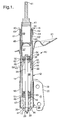
- FIG. 1 shows a monotube gas-charged suspension strut assembly 10 .
- the strut 10 is designed for operation as a load-bearing and shock-absorbing device within a vehicle suspension, and is connected between the sprung (body) and unsprung (wheel assembly) masses.
- Strut 10 comprises a housing 12 that includes a housing tube 14 with an open end 15 and a closed end 16 that may be formed by a spin closing operation, or by welding or otherwise securing a secondary component to the housing tube 14 .
- the closed end 16 includes an opening 17 .
- a mounting bracket 18 includes a cylindrical body 19 that is closely received over the housing tube 14 near closed end 16 and is secured in position by a suitable means such as welding.
- the bracket assembly 18 also has a pair of arms 20 that exhibit suitable openings for connection to the unsprung mass of the vehicle at a location such as the steering knuckle (not illustrated).
- a spring seat 21 is also received on the housing tube 14 and is located in position as required by the particular application within which the strut 10 will operate.
- the spring seat 21 is fixed in position on the housing tube 14 by a suitable means such as welding. Further details of the housing tube are described in U.S. Patent No. 5,984,060, the disclosure of which is hereby incorporated by reference.
- a piston assembly 25 is connected to a piston rod 26 and is fixed in position within the housing tube 14 .
- the piston rod 26 extends through the opening 17 with a reduced diameter segment 27 of the piston rod 26 captured within the opening 17 between shoulder 28 and flanged nut 29 .
- a pair of support plates 30 and 31 are positioned on opposite sides of the closed end 16 with the support plate 30 bearing against the shoulder 28 and the support plate 31 bearing against the flange of nut 29 .
- the support plate 30 includes an annular extension 31 that extends into the opening 17 and around the reduced diameter segment 27 .
- the piston assembly 25 includes a sintered steel piston body 34 that carries a band of low friction material 35 for engaging a damper body tube 40 . This provides a mechanism for fluid separation between extension chamber 36 and compression chamber 37 .
- a number of openings 38 are provided in the piston body 34 , which are normally closed by a monodisc valve assembly 39 .
- the openings 38 provide a fluid route between the extension chamber 36 and the compression chamber 37 when a sufficient force is established to deflect the valve assembly 39 .
- the valve assembly 39 affects a selected pressure drop across the piston and a subsequent backpressure. Through this mechanism the strut 10 provides a selected damping response between the sprung and unsprung masses of the vehicle.
- the damper body tube 40 is slidingly received over the piston assembly 25 .
- Damper body tube 40 includes a first end 41 at an outboard position adapted to be connected to the sprung mass of the vehicle and includes a second end 42 at an inboard position.
- the end 42 is supported about the piston rod 26 by a floating rod guide assembly 43 that is fixed in position within the damper body tube 40 .
- the upper end of the rod guide assembly 43 is adapted to contact a rebound stop that comprises one or more elastomeric bushings 45 carried adjacent the piston assembly 25 . At maximum extension of the strut 10 , the bushing 45 is compressed against the upper end of the rod guide assembly 43 to cushion the deceleration of strut 10 .
- a plate 46 is carried near the rod guide assembly 43 by a bracket 51 that slips inside the end 42 of damper body tube 40 .
- the plate 46 is adapted to contact a jounce bumper 47 that comprises an elastomeric bushing and that is positioned against the support 30 at the closed end 16 of housing tube 14 and about the piston rod 26 .
- a gas cup 48 is also carried in the damper body tube 40 between the piston assembly 25 and the end 41 .
- the gas cup 48 carries a seal and slides along the inside of damper body tube 40 separating out a compensation chamber 49 from the compression chamber 37 .
- the compensation chamber 49 carries a compressible nitrogen gas supply.
- a decreasing or an increasing volume of the piston rod 26 is contained within the damper body tube 40 depending on the stroke position of the strut assembly 10 .
- the gas cup 48 slides compressing or expanding the compensation chamber 49 .
- the predominate means of supporting the damper body tube 40 within the reservoir tube 14 is provided by a bearing system 52 that is designed to reduce friction and improve durability of the strut 10 .
- the bearing system 52 includes a bearing sleeve 53 that is made of common steel in the present embodiment, and which includes a step 54 formed near its outboard end 56 and a step 55 formed near its inboard end 57 .
- the bearing sleeve 53 is slip-fit within the housing tube 14 near end 15 .
- Bearing sleeve 53 is maintained in position by a formed stop 59 at end 57 , and by a retaining cap 60 at end 56 that is pressed onto the end of housing tube 14 .
- the stop 59 is formed by a means such as roll-forming or dimpling.
- the bearing assembly 52 also includes a pair of plain bearings 61 and 62 that are pressed into the bearing sleeve 53 with the bearing 61 positioned near end 56 and the bearing 62 positioned near end 57 .
- a seal 63 is positioned against the step 54 and bears against the damper body tube 40 .
- a seal 64 is positioned against the step 55 and bears against the damper body tube 40 .
- This provides a fluid-tight chamber 65 between the bearings 61 and 62 , which is filled with oil.
- the oil in chamber 65 is in a fluid form at room temperature and is preferably comprised of a formulated synthetic hydrocarbon based polyalphaolefinic bearing oil. This preferred oil is selected because it provides the film strength of a natural paraffinic petroleum oil with improved performance in the areas of volatility, temperature, operating range, and viscosity stability.
- FIG. 2 shows the floating rod guide assembly 43 in greater detail.
- the rod guide assembly 43 includes a seal cover 70, three O-rings 72, 74 and 76, a rod guide 78 , a dynamic rod seal 80 , and a retainer 82 .
- the seal cover 70 is preferrably steel, plated with Teflon impregnated nickel for reduced sliding friction and improved corrosion resistance.
- the seal cover 70 houses the other component parts and is attached to the inside of the cartridge tube 40 by a snap ring placed in a machined groove 83.
- the static O-ring seal 72 creates a seal between the outside of the seal cover 70 and the inside of the cartridge tube 40 .
- the rod guide 78 is preferably aluminum, and may be be coated with a material that works well as a lubricated bearing for low sliding friction and good wear properties.
- the annulus area 84 between the outside diameter of the rod guide 78 and the inside diameter of the seal cover 70 is filled with a grease.
- the O-ring seal 74 keeps the fluid and grease in the annulus area 84.
- the other sealing O-ring 76 also keeps the grease inside the seal cover 70 , and keeps most of the fluid from mixing with the grease.
- Each of the O-rings 74 and 76 works as a spring to provide a preload to the other, and they also eliminate any noise from the rod guide 78 hitting the seal cover 70 .
- the rod seal 80 seals the fluid inside the damper as the piston rod 26 slides in and out.
- the retainer 82 is crimped into the seal cover 70 , and holds the rod guide 78 inside the seal cover.
- the damper When the damper is assembled and pressurized, a small amount of fluid may leak around the retainer crimp until the pressure inside the seal cover 70 is equal to the pressure inside the damper. Because the outside diameter of the rod guide 78 is smaller than the inside diameter of the seal cover 70 , the rod guide can move laterally to account for any misalignment and to take up any bending of the piston rod 26 .
- the combination of plating materials, seals, and grease allows the force needed to move the rod guide laterally to be very low. Accordingly, the present invention operates with acceptable force and friction levels and reduces the incidence of premature rod wear.
- the chambers 36 and 37 may be filled with a magnetorheological (MR) fluid.
- MR fluids normally include fine iron particles dispersed within a liquid carrier such as hydraulic oils and the like. These MR fluids exhibit a thickening behavior (a rheology change), sometimes referred to as an "apparent viscosity change", upon being exposed to a magnetic field of sufficient strength. The higher the magnetic field strength to which the MR fluid is exposed, the higher the differential pressure (flow restriction or damping force) that can be achieved within the device.
- a particular advantage achieved by the present invention is that the area 84 is mostly insulated from the ingress of particles in the MR fluid, thus lessening axial friction and promoting the lifetime of the part.
- FIG. 3 shows an alternative embodiment of the floating rod guide assembly including a seal cover 90, four O-rings 92, 94, 96 and 97, a rod guide 98, a dynamic rod seal 100 , and a retainer 102 .
- the annulus area 104 between the outside diameter of the rod guide 98 and the inside diameter of the seal cover 100 is vacant, i.e. not filled with grease.
- An additional modification includes situation of the O-ring 97 in a groove in the retainer 102, and the press fit of the retainer into into the seal cover 90 . This design may offer manufacturing advantages under certain circumstances.
Landscapes
- Engineering & Computer Science (AREA)
- General Engineering & Computer Science (AREA)
- Mechanical Engineering (AREA)
- Physics & Mathematics (AREA)
- Electromagnetism (AREA)
- Vehicle Body Suspensions (AREA)
- Fluid-Damping Devices (AREA)
Abstract
Description
- The present invention relates to monotube strut assemblies, and more particularly to a floating rod guide for a monotube strut.
- A strut is a type of damper that is used in vehicle suspensions as both a damping device for providing shock absorbing functions and as part of the suspension's load-bearing structure. Monotube gas-charged dampers are known wherein a piston with a connected piston rod is slidably carried in a fluid-filled tube with a separate piston called a gas cup slidably carried in the tube on an opposite side of the piston from the rod. The gas cup separates a compressible gas charge from the fluid within the damper. It is known that monotube gas-charged dampers exhibit desirable performance characteristics when used in some suspension assemblies.
- Typically, the generic monotube strut design configuration is produced primarily as an aftermarket replacement damper, although limited original equipment (OEM) applications have been implemented. The prior art device generally includes a bearing mechanism that includes a combination of a polytetrafluoroethylene laminated plain bearing and a grease lubricant. In some applications performance advantages of high pressure monotube dampers are well known and therefore, the use of such devices without restriction would be desirable. However, in applying a monotube gas-charged strut in an OEM application, extended durability requirements lead to restrictions in the use of such devices, particularly in applications involving larger and heavier vehicles that operate with resultant increased side loading. In particular, the bearings in such a strut must be assembled and maintained in a straight and true fashion in order to obtain acceptable force and friction levels. In active struts that use magneto-rheologic fluid, moreover, there is a tendency for the fine iron particles that are in suspension to settle to the bottom of the unit. A cavity of a floating rod guide in this application may get packed with the iron particles, and lose its ability to float. Again this leads to premature rod wear and high damper axial friction.
- The present invention is a guide assembly for a rod of a motor vehicle strut. The guide assembly comprises a rod guide, a seal cover, and a retainer. The seal cover engages the rod guide, and defines an area therebetween. The retainer is engaged with the seal cover. A first O-ring is disposed between the seal cover and the rod guide, and a second O-ring is disposed between the rod guide and the retainer.
- Accordingly, it is an object of the present invention to provide a guide for a rod of a motor vehicle strut of the type described above which has acceptable force and friction levels.
- Another object of the present invention is to provide a rod guide of the type described above which reduces the incidence of premature rod wear.
- Still another object of the present invention is to provide a rod guide of the type described above which is acceptable for use in active struts, particularly those that use magneto-rheologic fluid.
- The foregoing and other features and advantages of the invention will become further apparent from the following detailed description of the presently preferred embodiments, read in conjunction with the accompanying drawings. The detailed description and drawings are merely illustrative of the invention rather than limiting, the scope of the invention being defined by the appended claims and equivalents thereof.
-
- FIG. 1 is a cross-sectional view of a monotube strut including a rod guide according to the present invention;
- FIG. 2 is an enlarged cross-sectional view of the rod guide; and
- FIG. 3 is an enlarged cross-sectional view of an alternative embodiment of the rod guide.
- FIG. 1 shows a monotube gas-charged
suspension strut assembly 10. In general thestrut 10 is designed for operation as a load-bearing and shock-absorbing device within a vehicle suspension, and is connected between the sprung (body) and unsprung (wheel assembly) masses.Strut 10 comprises ahousing 12 that includes ahousing tube 14 with anopen end 15 and a closedend 16 that may be formed by a spin closing operation, or by welding or otherwise securing a secondary component to thehousing tube 14. The closedend 16 includes an opening 17. Amounting bracket 18 includes acylindrical body 19 that is closely received over thehousing tube 14 near closedend 16 and is secured in position by a suitable means such as welding. Thebracket assembly 18 also has a pair ofarms 20 that exhibit suitable openings for connection to the unsprung mass of the vehicle at a location such as the steering knuckle (not illustrated). Aspring seat 21 is also received on thehousing tube 14 and is located in position as required by the particular application within which thestrut 10 will operate. Thespring seat 21 is fixed in position on thehousing tube 14 by a suitable means such as welding. Further details of the housing tube are described in U.S. Patent No. 5,984,060, the disclosure of which is hereby incorporated by reference. - A
piston assembly 25 is connected to apiston rod 26 and is fixed in position within thehousing tube 14. Thepiston rod 26 extends through theopening 17 with a reduced diameter segment 27 of thepiston rod 26 captured within the opening 17 betweenshoulder 28 and flangednut 29. A pair ofsupport plates end 16 with thesupport plate 30 bearing against theshoulder 28 and thesupport plate 31 bearing against the flange ofnut 29. Thesupport plate 30 includes anannular extension 31 that extends into theopening 17 and around the reduced diameter segment 27. - The
piston assembly 25 includes a sinteredsteel piston body 34 that carries a band oflow friction material 35 for engaging adamper body tube 40. This provides a mechanism for fluid separation betweenextension chamber 36 andcompression chamber 37. A number ofopenings 38 are provided in thepiston body 34, which are normally closed by amonodisc valve assembly 39. Theopenings 38 provide a fluid route between theextension chamber 36 and thecompression chamber 37 when a sufficient force is established to deflect thevalve assembly 39. As fluid flow is forced through theopenings 38, thevalve assembly 39 affects a selected pressure drop across the piston and a subsequent backpressure. Through this mechanism thestrut 10 provides a selected damping response between the sprung and unsprung masses of the vehicle. - The
damper body tube 40 is slidingly received over thepiston assembly 25.Damper body tube 40 includes afirst end 41 at an outboard position adapted to be connected to the sprung mass of the vehicle and includes asecond end 42 at an inboard position. Theend 42 is supported about thepiston rod 26 by a floatingrod guide assembly 43 that is fixed in position within thedamper body tube 40. The upper end of therod guide assembly 43 is adapted to contact a rebound stop that comprises one or moreelastomeric bushings 45 carried adjacent thepiston assembly 25. At maximum extension of thestrut 10, thebushing 45 is compressed against the upper end of therod guide assembly 43 to cushion the deceleration ofstrut 10. Aplate 46 is carried near therod guide assembly 43 by abracket 51 that slips inside theend 42 ofdamper body tube 40. Theplate 46 is adapted to contact ajounce bumper 47 that comprises an elastomeric bushing and that is positioned against thesupport 30 at the closedend 16 ofhousing tube 14 and about thepiston rod 26. - A
gas cup 48 is also carried in thedamper body tube 40 between thepiston assembly 25 and theend 41. Thegas cup 48 carries a seal and slides along the inside ofdamper body tube 40 separating out acompensation chamber 49 from thecompression chamber 37. While theextension chamber 36 andcompression chamber 37 carry a supply of hydraulic fluid, thecompensation chamber 49 carries a compressible nitrogen gas supply. During extension and compression directed travel of thedamper body tube 40 relative to thepiston assembly 25, a decreasing or an increasing volume of thepiston rod 26 is contained within thedamper body tube 40 depending on the stroke position of thestrut assembly 10. In order to compensate for this varying volumetric amount of thepiston rod 26 within the fluid-filledchambers gas cup 48 slides compressing or expanding thecompensation chamber 49. - The predominate means of supporting the
damper body tube 40 within thereservoir tube 14 is provided by abearing system 52 that is designed to reduce friction and improve durability of thestrut 10. Thebearing system 52 includes abearing sleeve 53 that is made of common steel in the present embodiment, and which includes astep 54 formed near itsoutboard end 56 and astep 55 formed near itsinboard end 57. Thebearing sleeve 53 is slip-fit within thehousing tube 14 nearend 15. Bearingsleeve 53 is maintained in position by a formedstop 59 atend 57, and by a retainingcap 60 atend 56 that is pressed onto the end ofhousing tube 14. Thestop 59 is formed by a means such as roll-forming or dimpling. - The bearing
assembly 52 also includes a pair ofplain bearings 61 and 62 that are pressed into the bearingsleeve 53 with the bearing 61 positioned nearend 56 and the bearing 62 positioned nearend 57. Aseal 63 is positioned against thestep 54 and bears against thedamper body tube 40. Aseal 64 is positioned against thestep 55 and bears against thedamper body tube 40. This provides a fluid-tight chamber 65 between thebearings 61 and 62, which is filled with oil. The oil inchamber 65 is in a fluid form at room temperature and is preferably comprised of a formulated synthetic hydrocarbon based polyalphaolefinic bearing oil. This preferred oil is selected because it provides the film strength of a natural paraffinic petroleum oil with improved performance in the areas of volatility, temperature, operating range, and viscosity stability. - FIG. 2 shows the floating
rod guide assembly 43 in greater detail. Therod guide assembly 43 includes aseal cover 70, three O-rings rod guide 78, adynamic rod seal 80, and aretainer 82. Theseal cover 70 is preferrably steel, plated with Teflon impregnated nickel for reduced sliding friction and improved corrosion resistance. The seal cover 70 houses the other component parts and is attached to the inside of thecartridge tube 40 by a snap ring placed in a machinedgroove 83. The static O-ring seal 72 creates a seal between the outside of theseal cover 70 and the inside of thecartridge tube 40. Therod guide 78 is preferably aluminum, and may be be coated with a material that works well as a lubricated bearing for low sliding friction and good wear properties. - The
annulus area 84 between the outside diameter of therod guide 78 and the inside diameter of theseal cover 70 is filled with a grease. The O-ring seal 74 keeps the fluid and grease in theannulus area 84. The other sealing O-ring 76 also keeps the grease inside theseal cover 70, and keeps most of the fluid from mixing with the grease. Each of the O-rings rod guide 78 hitting theseal cover 70. Therod seal 80 seals the fluid inside the damper as thepiston rod 26 slides in and out.
Theretainer 82 is crimped into theseal cover 70, and holds therod guide 78 inside the seal cover. - When the damper is assembled and pressurized, a small amount of fluid may leak around the retainer crimp until the pressure inside the
seal cover 70 is equal to the pressure inside the damper. Because the outside diameter of therod guide 78 is smaller than the inside diameter of theseal cover 70, the rod guide can move laterally to account for any misalignment and to take up any bending of thepiston rod 26. The combination of plating materials, seals, and grease allows the force needed to move the rod guide laterally to be very low. Accordingly, the present invention operates with acceptable force and friction levels and reduces the incidence of premature rod wear. - For continuously variable active dampers, the
chambers area 84 is mostly insulated from the ingress of particles in the MR fluid, thus lessening axial friction and promoting the lifetime of the part. - FIG. 3 shows an alternative embodiment of the floating rod guide assembly including a
seal cover 90, four O-rings rod guide 98, adynamic rod seal 100, and aretainer 102. In this embodiment, theannulus area 104 between the outside diameter of therod guide 98 and the inside diameter of theseal cover 100 is vacant, i.e. not filled with grease. An additional modification includes situation of the O-ring 97 in a groove in theretainer 102, and the press fit of the retainer into into theseal cover 90. This design may offer manufacturing advantages under certain circumstances. - While the embodiment of the invention disclosed herein is presently considered to be preferred, various changes and modifications can be made without departing from the spirit and scope of the invention. The scope of the invention is indicated in the appended claims, and all changes that come within the meaning and range of equivalents are intended to be embraced therein.
Claims (20)
- A guide assembly for a rod of a motor vehicle strut, the guide assembly comprising:a rod guide;a seal cover engaging the rod guide and defining an area therebetween;a retainer engaged with the seal cover;a first O-ring disposed between the seal cover and the rod guide; anda second O-ring disposed between the rod guide and the retainer.
- The guide assembly of claim 1 further comprising a rod seal engaging the rod guide, the rod seal being adapted to engage the rod of the strut.
- The guide assembly of claim 1 further comprising a third O-ring disposed proximate an outer surface of the seal cover.
- The guide assembly of claim 1 wherein the rod guide comprises aluminum.
- The guide assembly of claim 1 wherein the rod guide comprises a lubricious coating.
- The guide assembly of claim 1 wherein the area between the seal cover and the rod guide is annulus-shaped.
- The guide assembly of claim 1 wherein the area between the seal cover and the rod guide is filled with grease.
- The guide assembly of claim 1 wherein the seal cover comprises steel.
- The guide assembly of claim 1 wherein the seal cover comprises a plating.
- The guide assembly of claim 1 wherein the seal cover comprises a Teflon-impregnated nickel plating.
- A strut for a motor vehicle, the strut comprising:a body;a rod slidable within the body; anda guide assembly including:a rod guide;a seal cover engaging the rod guide and defining an area therebetween;a retainer engaged with the seal cover;a first O-ring disposed between the seal cover and the rod guide; anda second O-ring disposed between the rod guide and the retainer.
- The strut of claim 11 further comprising a rod seal engaging the rod guide, the rod seal being adapted to engage the rod.
- The strut of claim 11 further comprising a third O-ring disposed proximate an outer surface of the seal cover.
- The strut of claim 11 wherein the rod guide comprises aluminum.
- The strut of claim 11 wherein the rod guide comprises a lubricious coating.
- The strut of claim 11 wherein the area between the seal cover and the rod guide is annulus-shaped.
- The strut of claim 11 wherein the area between the seal cover and the rod guide is filled with grease.
- The strut of claim 11 wherein the seal cover comprises steel.
- The strut of claim 11 wherein the seal cover comprises a Teflon-impregnated nickel plating.
- A strut for a motor vehicle, the strut comprising:a body;a rod slidable within the body; anda guide assembly including:a rod guide having a lubricious coating;a seal cover engaging the rod guide and defining an annulus-shaped area therebetween;a retainer engaged with the seal cover;a first O-ring disposed between the seal cover and the rod guide;a second O-ring disposed between the rod guide and the retainer;a rod seal engaging the rod guide, the rod seal being adapted to engage the rod; anda third O-ring disposed proximate an outer surface of the seal cover.
Applications Claiming Priority (2)
| Application Number | Priority Date | Filing Date | Title |
|---|---|---|---|
| US917297 | 2001-07-27 | ||
| US09/917,297 US6390258B1 (en) | 2001-07-27 | 2001-07-27 | Floating rod guide for monotube strut |
Publications (2)
| Publication Number | Publication Date |
|---|---|
| EP1279857A2 true EP1279857A2 (en) | 2003-01-29 |
| EP1279857A3 EP1279857A3 (en) | 2003-11-19 |
Family
ID=25438580
Family Applications (1)
| Application Number | Title | Priority Date | Filing Date |
|---|---|---|---|
| EP02077795A Withdrawn EP1279857A3 (en) | 2001-07-27 | 2002-07-10 | Floating rod guide for monotube strut |
Country Status (2)
| Country | Link |
|---|---|
| US (1) | US6390258B1 (en) |
| EP (1) | EP1279857A3 (en) |
Cited By (2)
| Publication number | Priority date | Publication date | Assignee | Title |
|---|---|---|---|---|
| CN102788110A (en) * | 2012-08-17 | 2012-11-21 | 上海应用技术学院 | Dual-rod magnetorheological fluid damper and seal structure thereof |
| US10487901B2 (en) | 2017-01-09 | 2019-11-26 | Beijingwest Industries Co., Ltd. | Damping strut |
Families Citing this family (25)
| Publication number | Priority date | Publication date | Assignee | Title |
|---|---|---|---|---|
| US6640943B1 (en) * | 2002-08-13 | 2003-11-04 | Fox Factory, Inc. | Shock absorber with sealing ice scraper |
| US6840358B2 (en) | 2003-01-09 | 2005-01-11 | Delphi Technologies, Inc. | Floating rod guide for monotube strut |
| US7021435B2 (en) * | 2003-02-07 | 2006-04-04 | Delphi Technologies, Inc. | Monotube strut with rebound cut-off feature |
| US6981578B2 (en) | 2003-07-31 | 2006-01-03 | Troy Leiphart | Non-pressurized monotube shock absorber |
| US7011193B2 (en) * | 2004-02-13 | 2006-03-14 | Tenneco Automotive Operating Company Inc. | Rod guide and seal system for gas filled shock absorbers |
| ATE364803T1 (en) * | 2005-01-17 | 2007-07-15 | Delphi Tech Inc | HYDRAULIC MAGNETORHEOLOGICAL SHOCK ABSORBER |
| US7703587B2 (en) * | 2007-01-30 | 2010-04-27 | Zf Friedrichshafen Ag | Rod guide for monotube shock absorbers |
| US8763391B2 (en) | 2007-04-23 | 2014-07-01 | Deka Products Limited Partnership | Stirling cycle machine |
| CN101688500B (en) | 2007-04-23 | 2015-07-01 | 新动力概念有限公司 | Stirling cycle machine |
| CN201103307Y (en) * | 2007-09-30 | 2008-08-20 | 佛山市顺德区泰明金属制品厂有限公司 | Fluid buffer for furniture |
| US8215463B2 (en) * | 2008-02-12 | 2012-07-10 | Honda Motor Co., Ltd. | Variable damping-force damper and manufacturing method of the same |
| US20100116607A1 (en) * | 2008-11-07 | 2010-05-13 | Saiman Lun | Dual seal rod guide assembly with low friction disc |
| US9822730B2 (en) * | 2009-07-01 | 2017-11-21 | New Power Concepts, Llc | Floating rod seal for a stirling cycle machine |
| US9797341B2 (en) | 2009-07-01 | 2017-10-24 | New Power Concepts Llc | Linear cross-head bearing for stirling engine |
| US9828940B2 (en) | 2009-07-01 | 2017-11-28 | New Power Concepts Llc | Stirling cycle machine |
| EP2449244B1 (en) | 2009-07-01 | 2016-05-04 | New Power Concepts LLC | Stirling cycle machine |
| DE102011051710B3 (en) * | 2011-07-08 | 2012-08-16 | Stabilus Gmbh | Tension spring for locking doors or flaps of furniture, has cylinder which is divided in gas chamber and hydraulic chamber by piston, where gas chamber is filled with gas stands under pressure |
| CN105190001B (en) * | 2013-03-15 | 2018-07-17 | 新动力概念有限公司 | Stirling circulator |
| DE102013204745A1 (en) | 2013-03-19 | 2014-01-30 | Zf Friedrichshafen Ag | Reciprocating shaft seal for hydraulic vibration damper used for motor vehicle, has gasket that is provided with main seal lip that is placed on piston rod, while farther lip touches piston rod |
| JP6412339B2 (en) * | 2014-05-19 | 2018-10-24 | Kyb株式会社 | Shock absorber |
| DE102014223164B4 (en) * | 2014-11-13 | 2022-03-17 | Zf Friedrichshafen Ag | seal guiding unit |
| US10072723B2 (en) * | 2015-04-24 | 2018-09-11 | Beijingwest Industries Co., Ltd. | Closing assembly for a magneto-rheological damper |
| CN113217572B (en) * | 2020-05-27 | 2022-09-27 | 北京京西重工有限公司 | Damper assembly |
| CN111623070A (en) * | 2020-06-29 | 2020-09-04 | 赣州禾盈通用零部件有限公司 | Small-size big resistance buffer |
| US20240229889A1 (en) * | 2022-12-13 | 2024-07-11 | Fox Factory, Inc. | Air spring assembly |
Citations (1)
| Publication number | Priority date | Publication date | Assignee | Title |
|---|---|---|---|---|
| US5984060A (en) | 1997-08-25 | 1999-11-16 | General Motors Corporation | Monotube strut assembly |
Family Cites Families (12)
| Publication number | Priority date | Publication date | Assignee | Title |
|---|---|---|---|---|
| FR2184186A5 (en) * | 1972-05-10 | 1973-12-21 | Thomson Csf | |
| DE3026877C2 (en) * | 1980-07-16 | 1983-06-09 | Herbert Hänchen KG, 7302 Ostfildern | Low friction seal |
| DE3432606A1 (en) * | 1984-09-05 | 1986-03-13 | Stabilus Gmbh, 5400 Koblenz | PNEUMATIC OR HYDROPNEUMATIC TENSION SPRING |
| FR2582368B1 (en) * | 1985-05-22 | 1989-06-02 | Orflam Expl Ets | PERMANENT LUBRICATION GAS SPRING |
| US5115892A (en) * | 1988-09-27 | 1992-05-26 | Atsugi Unisia Corporation | Hydraulic shock absorber with piston seal structure for enhancement of initial response |
| JP2517808Y2 (en) * | 1990-05-10 | 1996-11-20 | 株式会社ユニシアジェックス | Rod guide for double cylinder type hydraulic shock absorber |
| DE4039173A1 (en) * | 1990-12-05 | 1992-06-11 | Mannesmann Ag | Piston rod seal - is free to move with piston rod, and has support incorporated in cylinder head |
| DE4106651A1 (en) * | 1991-03-02 | 1992-09-03 | Fichtel & Sachs Ag | GUIDE BODY UNIT WITH SLOPED SEAL |
| DE4236961A1 (en) * | 1992-11-02 | 1994-05-05 | Fichtel & Sachs Ag | Fire protection for a vibration damper |
| FR2709796B1 (en) * | 1993-08-06 | 1998-11-27 | Carbon Ste Fse Amortisseurs | One-piece sealing device with lubricated centering guide for pressurized hydraulic shock absorber tube. |
| DE19938084B4 (en) * | 1998-12-11 | 2005-11-24 | Daimlerchrysler Ag | Guide bearing in connection with a pressure cylinder, in particular damping element for motor vehicles |
| US6318526B1 (en) * | 1999-09-13 | 2001-11-20 | Delphi Technologies, Inc. | Compliant rod guide and seal assembly |
-
2001
- 2001-07-27 US US09/917,297 patent/US6390258B1/en not_active Expired - Fee Related
-
2002
- 2002-07-10 EP EP02077795A patent/EP1279857A3/en not_active Withdrawn
Patent Citations (1)
| Publication number | Priority date | Publication date | Assignee | Title |
|---|---|---|---|---|
| US5984060A (en) | 1997-08-25 | 1999-11-16 | General Motors Corporation | Monotube strut assembly |
Cited By (3)
| Publication number | Priority date | Publication date | Assignee | Title |
|---|---|---|---|---|
| CN102788110A (en) * | 2012-08-17 | 2012-11-21 | 上海应用技术学院 | Dual-rod magnetorheological fluid damper and seal structure thereof |
| CN102788110B (en) * | 2012-08-17 | 2015-03-04 | 上海应用技术学院 | Seal structure of dual-rod magnetorheological fluid damper |
| US10487901B2 (en) | 2017-01-09 | 2019-11-26 | Beijingwest Industries Co., Ltd. | Damping strut |
Also Published As
| Publication number | Publication date |
|---|---|
| US6390258B1 (en) | 2002-05-21 |
| EP1279857A3 (en) | 2003-11-19 |
Similar Documents
| Publication | Publication Date | Title |
|---|---|---|
| US6390258B1 (en) | Floating rod guide for monotube strut | |
| US5984060A (en) | Monotube strut assembly | |
| US6547044B2 (en) | Magneto-rheological damper with ferromagnetic housing insert | |
| US11181161B2 (en) | Shock absorber base valve assembly | |
| US6883649B2 (en) | Closing system for a magneto-rheological damper | |
| US7011193B2 (en) | Rod guide and seal system for gas filled shock absorbers | |
| US6840358B2 (en) | Floating rod guide for monotube strut | |
| US7216747B2 (en) | Amplitude controlled orifice valving | |
| US6918473B2 (en) | Stroke dependent bypass | |
| US6776269B1 (en) | Twin piston shock absorber | |
| US6220409B1 (en) | Stroke dependent bypass | |
| US7950506B2 (en) | Semi third tube design | |
| US9163691B2 (en) | Rod guide arrangement for electronically controlled valve applications | |
| CN114810911B (en) | Stroke dependent damper assembly | |
| US9533538B2 (en) | Low pressure high compression damping monotube shock absorber | |
| EP2392505A1 (en) | Magneto-rheological dampers for semi-active suspension systems | |
| US7070028B2 (en) | Frequency dependent damper | |
| WO2020231972A1 (en) | Hydraulic compression stop with biased piston | |
| US20010009214A1 (en) | Hydraulic damper for suspension systems | |
| US20020130002A1 (en) | Gas cup seal for magneto-rheological damper | |
| US20070051574A1 (en) | Rod guide seal | |
| US12331806B2 (en) | Telescopic passive damper | |
| JP3609964B2 (en) | damper | |
| US6364075B1 (en) | Frequency dependent damper |
Legal Events
| Date | Code | Title | Description |
|---|---|---|---|
| PUAI | Public reference made under article 153(3) epc to a published international application that has entered the european phase |
Free format text: ORIGINAL CODE: 0009012 |
|
| AK | Designated contracting states |
Designated state(s): AT BE BG CH CY CZ DE DK EE ES FI FR GB GR IE IT LI LU MC NL PT SE SK TR |
|
| AX | Request for extension of the european patent |
Extension state: AL LT LV MK RO SI |
|
| PUAL | Search report despatched |
Free format text: ORIGINAL CODE: 0009013 |
|
| RIN1 | Information on inventor provided before grant (corrected) |
Inventor name: LISENKER, ILYA Inventor name: HURTT, MICHAEL W. Inventor name: ROBINSON, STEVEN RAY Inventor name: HOFMANN, RANDALL L. |
|
| AK | Designated contracting states |
Kind code of ref document: A3 Designated state(s): AT BE BG CH CY CZ DE DK EE ES FI FR GB GR IE IT LI LU MC NL PT SE SK TR |
|
| AX | Request for extension of the european patent |
Extension state: AL LT LV MK RO SI |
|
| 17P | Request for examination filed |
Effective date: 20040519 |
|
| AKX | Designation fees paid |
Designated state(s): DE FR GB IT |
|
| 17Q | First examination report despatched |
Effective date: 20041015 |
|
| STAA | Information on the status of an ep patent application or granted ep patent |
Free format text: STATUS: THE APPLICATION IS DEEMED TO BE WITHDRAWN |
|
| 18D | Application deemed to be withdrawn |
Effective date: 20050426 |