EP1279817A2 - Control device and method of internal combustion engine - Google Patents
Control device and method of internal combustion engine Download PDFInfo
- Publication number
- EP1279817A2 EP1279817A2 EP02016639A EP02016639A EP1279817A2 EP 1279817 A2 EP1279817 A2 EP 1279817A2 EP 02016639 A EP02016639 A EP 02016639A EP 02016639 A EP02016639 A EP 02016639A EP 1279817 A2 EP1279817 A2 EP 1279817A2
- Authority
- EP
- European Patent Office
- Prior art keywords
- internal combustion
- combustion engine
- recovery process
- recovery
- engine
- Prior art date
- Legal status (The legal status is an assumption and is not a legal conclusion. Google has not performed a legal analysis and makes no representation as to the accuracy of the status listed.)
- Granted
Links
Images


Classifications
-
- F—MECHANICAL ENGINEERING; LIGHTING; HEATING; WEAPONS; BLASTING
- F02—COMBUSTION ENGINES; HOT-GAS OR COMBUSTION-PRODUCT ENGINE PLANTS
- F02N—STARTING OF COMBUSTION ENGINES; STARTING AIDS FOR SUCH ENGINES, NOT OTHERWISE PROVIDED FOR
- F02N11/00—Starting of engines by means of electric motors
- F02N11/08—Circuits specially adapted for starting of engines
- F02N11/0814—Circuits specially adapted for starting of engines comprising means for controlling automatic idle-start-stop
- F02N11/0818—Conditions for starting or stopping the engine or for deactivating the idle-start-stop mode
- F02N11/0829—Conditions for starting or stopping the engine or for deactivating the idle-start-stop mode related to special engine control, e.g. giving priority to engine warming-up or learning
-
- F—MECHANICAL ENGINEERING; LIGHTING; HEATING; WEAPONS; BLASTING
- F01—MACHINES OR ENGINES IN GENERAL; ENGINE PLANTS IN GENERAL; STEAM ENGINES
- F01N—GAS-FLOW SILENCERS OR EXHAUST APPARATUS FOR MACHINES OR ENGINES IN GENERAL; GAS-FLOW SILENCERS OR EXHAUST APPARATUS FOR INTERNAL-COMBUSTION ENGINES
- F01N3/00—Exhaust or silencing apparatus having means for purifying, rendering innocuous, or otherwise treating exhaust
- F01N3/08—Exhaust or silencing apparatus having means for purifying, rendering innocuous, or otherwise treating exhaust for rendering innocuous
- F01N3/0807—Exhaust or silencing apparatus having means for purifying, rendering innocuous, or otherwise treating exhaust for rendering innocuous by using absorbents or adsorbents
- F01N3/0828—Exhaust or silencing apparatus having means for purifying, rendering innocuous, or otherwise treating exhaust for rendering innocuous by using absorbents or adsorbents characterised by the absorbed or adsorbed substances
- F01N3/0842—Nitrogen oxides
-
- F—MECHANICAL ENGINEERING; LIGHTING; HEATING; WEAPONS; BLASTING
- F01—MACHINES OR ENGINES IN GENERAL; ENGINE PLANTS IN GENERAL; STEAM ENGINES
- F01N—GAS-FLOW SILENCERS OR EXHAUST APPARATUS FOR MACHINES OR ENGINES IN GENERAL; GAS-FLOW SILENCERS OR EXHAUST APPARATUS FOR INTERNAL-COMBUSTION ENGINES
- F01N3/00—Exhaust or silencing apparatus having means for purifying, rendering innocuous, or otherwise treating exhaust
- F01N3/08—Exhaust or silencing apparatus having means for purifying, rendering innocuous, or otherwise treating exhaust for rendering innocuous
- F01N3/0807—Exhaust or silencing apparatus having means for purifying, rendering innocuous, or otherwise treating exhaust for rendering innocuous by using absorbents or adsorbents
- F01N3/0871—Exhaust or silencing apparatus having means for purifying, rendering innocuous, or otherwise treating exhaust for rendering innocuous by using absorbents or adsorbents using means for controlling, e.g. purging, the absorbents or adsorbents
-
- F—MECHANICAL ENGINEERING; LIGHTING; HEATING; WEAPONS; BLASTING
- F02—COMBUSTION ENGINES; HOT-GAS OR COMBUSTION-PRODUCT ENGINE PLANTS
- F02D—CONTROLLING COMBUSTION ENGINES
- F02D41/00—Electrical control of supply of combustible mixture or its constituents
- F02D41/02—Circuit arrangements for generating control signals
- F02D41/04—Introducing corrections for particular operating conditions
- F02D41/042—Introducing corrections for particular operating conditions for stopping the engine
-
- F—MECHANICAL ENGINEERING; LIGHTING; HEATING; WEAPONS; BLASTING
- F02—COMBUSTION ENGINES; HOT-GAS OR COMBUSTION-PRODUCT ENGINE PLANTS
- F02M—SUPPLYING COMBUSTION ENGINES IN GENERAL WITH COMBUSTIBLE MIXTURES OR CONSTITUENTS THEREOF
- F02M26/00—Engine-pertinent apparatus for adding exhaust gases to combustion-air, main fuel or fuel-air mixture, e.g. by exhaust gas recirculation [EGR] systems
- F02M26/13—Arrangement or layout of EGR passages, e.g. in relation to specific engine parts or for incorporation of accessories
- F02M26/22—Arrangement or layout of EGR passages, e.g. in relation to specific engine parts or for incorporation of accessories with coolers in the recirculation passage
- F02M26/33—Arrangement or layout of EGR passages, e.g. in relation to specific engine parts or for incorporation of accessories with coolers in the recirculation passage controlling the temperature of the recirculated gases
-
- F—MECHANICAL ENGINEERING; LIGHTING; HEATING; WEAPONS; BLASTING
- F01—MACHINES OR ENGINES IN GENERAL; ENGINE PLANTS IN GENERAL; STEAM ENGINES
- F01N—GAS-FLOW SILENCERS OR EXHAUST APPARATUS FOR MACHINES OR ENGINES IN GENERAL; GAS-FLOW SILENCERS OR EXHAUST APPARATUS FOR INTERNAL-COMBUSTION ENGINES
- F01N2610/00—Adding substances to exhaust gases
- F01N2610/03—Adding substances to exhaust gases the substance being hydrocarbons, e.g. engine fuel
-
- F—MECHANICAL ENGINEERING; LIGHTING; HEATING; WEAPONS; BLASTING
- F02—COMBUSTION ENGINES; HOT-GAS OR COMBUSTION-PRODUCT ENGINE PLANTS
- F02B—INTERNAL-COMBUSTION PISTON ENGINES; COMBUSTION ENGINES IN GENERAL
- F02B2275/00—Other engines, components or details, not provided for in other groups of this subclass
- F02B2275/14—Direct injection into combustion chamber
-
- F—MECHANICAL ENGINEERING; LIGHTING; HEATING; WEAPONS; BLASTING
- F02—COMBUSTION ENGINES; HOT-GAS OR COMBUSTION-PRODUCT ENGINE PLANTS
- F02B—INTERNAL-COMBUSTION PISTON ENGINES; COMBUSTION ENGINES IN GENERAL
- F02B29/00—Engines characterised by provision for charging or scavenging not provided for in groups F02B25/00, F02B27/00 or F02B33/00 - F02B39/00; Details thereof
- F02B29/04—Cooling of air intake supply
- F02B29/0406—Layout of the intake air cooling or coolant circuit
-
- F—MECHANICAL ENGINEERING; LIGHTING; HEATING; WEAPONS; BLASTING
- F02—COMBUSTION ENGINES; HOT-GAS OR COMBUSTION-PRODUCT ENGINE PLANTS
- F02B—INTERNAL-COMBUSTION PISTON ENGINES; COMBUSTION ENGINES IN GENERAL
- F02B37/00—Engines characterised by provision of pumps driven at least for part of the time by exhaust
-
- F—MECHANICAL ENGINEERING; LIGHTING; HEATING; WEAPONS; BLASTING
- F02—COMBUSTION ENGINES; HOT-GAS OR COMBUSTION-PRODUCT ENGINE PLANTS
- F02M—SUPPLYING COMBUSTION ENGINES IN GENERAL WITH COMBUSTIBLE MIXTURES OR CONSTITUENTS THEREOF
- F02M26/00—Engine-pertinent apparatus for adding exhaust gases to combustion-air, main fuel or fuel-air mixture, e.g. by exhaust gas recirculation [EGR] systems
- F02M26/02—EGR systems specially adapted for supercharged engines
- F02M26/04—EGR systems specially adapted for supercharged engines with a single turbocharger
- F02M26/05—High pressure loops, i.e. wherein recirculated exhaust gas is taken out from the exhaust system upstream of the turbine and reintroduced into the intake system downstream of the compressor
-
- F—MECHANICAL ENGINEERING; LIGHTING; HEATING; WEAPONS; BLASTING
- F02—COMBUSTION ENGINES; HOT-GAS OR COMBUSTION-PRODUCT ENGINE PLANTS
- F02M—SUPPLYING COMBUSTION ENGINES IN GENERAL WITH COMBUSTIBLE MIXTURES OR CONSTITUENTS THEREOF
- F02M26/00—Engine-pertinent apparatus for adding exhaust gases to combustion-air, main fuel or fuel-air mixture, e.g. by exhaust gas recirculation [EGR] systems
- F02M26/13—Arrangement or layout of EGR passages, e.g. in relation to specific engine parts or for incorporation of accessories
- F02M26/22—Arrangement or layout of EGR passages, e.g. in relation to specific engine parts or for incorporation of accessories with coolers in the recirculation passage
- F02M26/23—Layout, e.g. schematics
-
- Y—GENERAL TAGGING OF NEW TECHNOLOGICAL DEVELOPMENTS; GENERAL TAGGING OF CROSS-SECTIONAL TECHNOLOGIES SPANNING OVER SEVERAL SECTIONS OF THE IPC; TECHNICAL SUBJECTS COVERED BY FORMER USPC CROSS-REFERENCE ART COLLECTIONS [XRACs] AND DIGESTS
- Y02—TECHNOLOGIES OR APPLICATIONS FOR MITIGATION OR ADAPTATION AGAINST CLIMATE CHANGE
- Y02C—CAPTURE, STORAGE, SEQUESTRATION OR DISPOSAL OF GREENHOUSE GASES [GHG]
- Y02C20/00—Capture or disposal of greenhouse gases
- Y02C20/10—Capture or disposal of greenhouse gases of nitrous oxide (N2O)
-
- Y—GENERAL TAGGING OF NEW TECHNOLOGICAL DEVELOPMENTS; GENERAL TAGGING OF CROSS-SECTIONAL TECHNOLOGIES SPANNING OVER SEVERAL SECTIONS OF THE IPC; TECHNICAL SUBJECTS COVERED BY FORMER USPC CROSS-REFERENCE ART COLLECTIONS [XRACs] AND DIGESTS
- Y02—TECHNOLOGIES OR APPLICATIONS FOR MITIGATION OR ADAPTATION AGAINST CLIMATE CHANGE
- Y02T—CLIMATE CHANGE MITIGATION TECHNOLOGIES RELATED TO TRANSPORTATION
- Y02T10/00—Road transport of goods or passengers
- Y02T10/10—Internal combustion engine [ICE] based vehicles
- Y02T10/40—Engine management systems
Definitions
- This invention relates to a control device and method of an internal combustion engine such as a diesel engine. Especially, the invention relates to the control device and method of the internal combustion engine equipped with an exhaust system including an exhaust purification device which needs to perform a recovery process to recover purification capability, and the control method.
- An internal combustion engine such as a diesel engine outputs power by combusting fuel, so that the engine inevitably generates exhaust gas, however, from the viewpoint of preservation of the global environment, it is required to purify the exhaust gas generated from the internal combustion engine quickly.
- An example of so-called contaminated substances contained in the exhaust gas of the internal combustion engine is particulate matter (PM) such as hydrocarbon or smoke and nitrogen oxide (NOx). It is required to reduce the discharge quantity.
- PM particulate matter
- NOx nitrogen oxide
- the quantity of these substances in the exhaust gas can be reduced by controlling an operation condition of the internal combustion engine such as air-fuel ratio and fuel injection timing or an exhaust recirculation quantity reintroducing part of exhaust gas into an intake side.
- an operation condition of the internal combustion engine such as air-fuel ratio and fuel injection timing or an exhaust recirculation quantity reintroducing part of exhaust gas into an intake side.
- an exhaust system of the internal combustion engine is equipped with an exhaust purification device, and is structured to transform so-called contaminated substances generated from the internal combustion engine into harmless substances and to release them into the air.
- the exhaust purification device is the catalyst and is structured so that contaminated substances in the exhaust gas are oxidized or deoxidized through the catalyst.
- a device disclosed in a Japanese Patent Laid-Open Publication No.2000-97063 is structured to prohibit suspending an engine even if the engine is in idling when catalyst temperature is equal to or lower than a predetermined temperature. This is to raise the catalyst temperature rapidly by a continuous engine operation.
- Catalyst in general, functions to promote reactions such as oxidization, and does not transform in itself, therefore, the continuous engine operation promotes the raise of the catalyst temperature by heat brought from the engine and by heat generated by the reaction through the catalyst.
- an occlusion-deoxidization type catalyst purifying NOx is known as an exhaust purification catalyst, and as this type of catalyst occludes the contaminated substances such as NOx temporarily, a purification capability saturates according as an occlusion quantity reaches saturation. That is, as some types of the exhaust purification catalyst gradually deteriorates the purification capability by the continuous engine operation, above-mentioned, when the engine continues to be operated even if in idling, the occlusion quantity (purification capability) reaches saturation early.
- the device disclosed in the publication presupposes suspending the engine in idling.
- the reason is that the device of the publication is subject to a hybrid vehicle and that the device restricts lowering of fuel consumption resulting from an unnecessary engine operation.
- the control for forcibly suspending the engine in idling is performed not only over the hybrid vehicle, and such control for suspending the engine is often named "Economy Running Control.” This is the control to suspend the engine, for instance, in case that a vehicle stops at a stoplight and that a predetermined condition is satisfied.
- the occlusion quantity of the catalyst does not increase because of generating no exhaust gas while the engine is in suspension.
- the recovery process for reducing the occlusion quantity is not performed, either.
- the recovery process is a process to supply a reducing agent such as, e.g., fuel into the catalyst and to deoxidize nitrate nitrogen occluded in the catalyst and change it into nitrogen gas, and as occluded nitrogen is released, the purification capability of the catalyst is recovered.
- the reducing agent is supplied into the exhaust gas when the engine suspends during such recovery process, the reducing agent does not reach the catalyst and is consumed in vain, or unused reducing agent causes problems such as temporary increase of HC (hydrocarbon) emission quantity. Moreover, when the engine suspends just before performing the recovery process, in next drive, the occlusion quantity of the catalyst is almost in saturation and the catalyst temperature is in low, therefore, it is possible that NOx cannot be purified.
- An object of the invention is to provide the control device which enables to perform with mutually adjusting the suspension control of the internal combustion engine and the recovery process of the catalyst appropriately.
- the invention provides a control device and method of an internal combustion engine reserving temporarily a control based on a stop demand of the internal combustion engine, in case that both the stop demand of the internal combustion engine and a recovery control of an exhaust purification device are simultaneously set.
- a first aspect of the present invention relates to the control device of the internal combustion engine which is equipped with an exhaust system including the exhaust purification device purifying exhaust gas, and which performs the recovery process to recover purification capability of the exhaust purification device in operation of the internal combustion engine.
- This device includes a first means for determining whether the need for recovery for recovering the purification capability of the exhaust purification device is present, a second means for determining whether the stop demand for stopping the internal combustion engine is present, and a third means for giving priority to the recovery process based on the need for recovery in case that both the need for recovery and the stop demand is present.
- the first aspect of the present invention it is determined whether the need for recovery for recovering the purification capability of the exhaust purification device is present, moreover, it is determined whether the stop demand for stopping the internal combustion engine is present.
- the need for recovery has been eliminated, the internal combustion engine is stopped.
- the recovery process based on the need for recovery is given priority. Therefore, there is a case that the operation is continued without an immediate stop of the internal combustion engine even if the stop demand of the internal combustion engine is present, the recovery process of the exhaust purification device is performed during the operation, and the purification capability can be recovered. Moreover, problems such as an interruption of the recovery process and ineffectiveness caused by the interruption can be previously prevented.
- the third means may stop the internal combustion engine based on the stop demand, after it is determined that the need for recovery has been eliminated.
- the first means determines the state of performing the recovery process
- the third means may delay the stop of the internal combustion engine based on the stop demand according to the result of the determination of the first means.
- the state of performing the recovery process of the purification capability of the exhaust purification device is determined, the stop control of the internal combustion engine is delayed based on the content of the determination. For that reason, there is a case that the operation is continued without the immediate stop of the internal combustion engine even if the stop demand of the internal combustion engine is present, the recovery process of the exhaust purification device is performed during the operation, and the purification capability can be recovered. Moreover, problems such as an interruption of the recovery process and ineffectiveness caused by the interruption can be previously prevented.
- the first means determines whether the recovery process is performed, and the third means may delay the stop of the internal combustion engine based on the stop demand until the recovery process is terminated.
- the first means determines whether the recovery process is started within a predetermined time from when it is determined that the stop demand for stopping the internal combustion engine is present, and the third means may delay the stop of the internal combustion engine based on the stop demand until the recovery process is terminated.
- the internal combustion engine is not stopped even if the stop demand of the internal combustion engine is present, and the operation of the internal combustion engine is continued until the recovery process is terminated. For that reason, at the time when the internal combustion engine is stopped, the purification capability of the exhaust purification device has been recovered, therefore, a processing capability of the exhaust purification device can be maintained to be sufficiently high when restarting the internal combustion engine.
- the third means may stop the internal combustion engine based on the stop demand after the recovery process has been performed.
- the recovery process of the purification capability of the exhaust purification device is performed. Therefore, when restarting the internal combustion engine, the process capability of the exhaust purification device can be maintained to be sufficiently high. Moreover, as the recovery process is performed in the condition that the operation of the internal combustion engine is being continued, the recovery process can be performed efficiently and rapidly.
- the first means determines the level of a requirement performing the recovery process, and determines whether the need for recovery is present based on the level of the requirement.
- the third means may stop the internal combustion engine after the recovery process is terminated based on the need for recovery .
- the level of the requirement of the recovery process at that time is determined, and the recovery process is performed based on the determination result.
- the level of the requirement of the recovery process is low, the internal combustion engine is stopped without the recovery process being performed, and inversely, in case that the level of the requirement of the recovery process is high, the internal combustion engine is stopped after the recovery process has been performed.
- the purification capability of the exhaust purification device can be maintained to be sufficiently high when restarting the internal combustion engine without the excessive number of performances of the recovery process.
- the exhaust purification device occludes NOx, and the purification capability may be capability to occlude the NOx.
- the recovery process may be a process to remove NOx occluded in the exhaust purification device.
- a second aspect in the present invention relates to the control method of the internal combustion engine which is equipped with the exhaust system including the exhaust purification device purifying the exhaust gas and which performs the recovery process to recover the purification capability of the exhaust purification device in operation of the internal combustion engine.
- This method includes the first step determining whether the need for recovery for recovering the purification capability of the exhaust purification device is present, the second step determining whether the stop demand for stopping the internal combustion engine is present, and the third step of stopping the internal combustion engine based on the stop demand determined at the second step when that the need for recovery has been eliminated is determined at the first step.
- the need for recovery may be present thourhout the recovery process is being performed, and at the third step, the internal combustion engine may be stopped after the recovery process is terminated.
- control method may include the fourth step to start the recovery process based on the need for recovery , and may stop the internal combustion engine after the recovery process is terminated at the third step.
- the first step based on the fuel supply quantity into the internal combustion engine after the last recovery process has been performed, it may be determined whether the requirement for performing the recovery process is present.
- the exhaust purification device may occlude NOx, and it may be determined whether the quantity of NOx occlusion is more than the predetermined value at the first step, and when it is determined that the quantity of NOx occlusion is more than the predetermined value, it may be determined that the need for recovery is present.
- An internal combustion engine includes a power device which outputs power by combusting fuel such as a diesel engine and a gasoline engine, and an example is the internal combustion engine which is mounted on a vehicle and is used as a power source mainly for running.
- Fig. 4 schematically shows an example of use of a direct injection type diesel engine 1 (hereinafter, refer to simply as an engine) as the power source of the vehicle in the first through the third preferred embodiments.
- This engine 1 is the internal combustion engine to directly inject fuel into the inside of a cylinder, and is equipped with a common-rail type electronic control fuel injection system 2 to enable fuel injection at high pressure.
- a common-rail type electronic control fuel injection system 2 to enable fuel injection at high pressure.
- One of the publicly known structure can be used for this electronic control fuel injection system 2.
- the engine 1 shown in Fig.4 is equipped with an exhaust turbine type supercharged engine i.e. turbocharger 3.
- An intake pipe 6 interposing an air cleaner 5 is connected with an air intake of a compressor 4, and an intake manifold 8 is connected with a delivery hole of the compressor 4 through an intercooler 7 to drop an intake temperature.
- an exhaust manifold 9 which is communicatively connected with each cylinder is connected with an inflow hole of a turbine 10 in the turbocharger 3. Furthermore, a catalyst converter 11 equipped with an exhaust purification catalyst is connected with an outlet of the turbine 10. At an upper side of this catalyst converter 11, an air-fuel ratio sensor 12 and a pressure sensor 13 which detects pressure of an exhaust gas flowing in the catalyst converter 11, are placed. Furthermore, a temperature sensor 14 for detecting the catalyst temperature is placed. This route from the exhaust manifold 9 to an opening (not shown) to the atmosphere through the catalyst converter 11 is an exhaust route.
- the exhaust purification catalyst shown in Fig.4 is an NOx occlusion-deoxidization type catalyst. This has functions to occlude NOx which is one of the contaminated substances in the exhaust gas in an oxidized atmosphere, in the form of nitrate nitrogen, to deoxidize the occluded nitrate nitrogen in a deoxidized atmosphere and change it into nitrogen gas and to release it. Furthermore, as an activated oxygen is generated in the occlusion and in the deoxidization of NOx, the exhaust purification catalyst has functions to oxidize soot (PM: micro particle discharge) adhering to a surface of the catalyst and to remove it by the activated oxygen and the oxygen in the exhaust gas.
- PM micro particle discharge
- the engine 1 is structured to perform such changes of atmospheres by switching over an air-fuel ratio to an air excessive lean air-fuel ratio (an air-fuel ratio larger than a theoretical air-fuel ratio) and to a rich air-fuel ratio to be relatively increased fuel quantity (an air-fuel ratio less than the theoretical air-fuel ratio).
- the control to increase the air-fuel ratio to release nitrogenous substance from the exhaust purification catalyst may be temporary, and such temporary increase of the air-fuel ratio is named "Rich Spike,” which is an example of the control equivalent to "recovery process.”
- the engine 1 shown in Fig.4 is equipped with an exhaust recirculation device to reduce NOx in the exhaust gas. That is, the exhaust manifold 9 and the intake manifold 8 are connected via an EGR cooler 15 cooling the exhaust gas recirculated and an EGR valve 16 performing the control of initiation and termination of recirculation and the control maintaining a fixed recirculation ratio (EGR ratio).
- EGR ratio a fixed recirculation ratio
- a continuously variable transmission 17 (CVT) is connected with the engine 1 output side.
- CVT 17 is a transmission to enable to change a shift ratio continuously, and any other type, such as a belt type CVT and a traction type (troydal type) CVT can be adopted.
- An electronic control unit for the engine (E-ECU) 18 to electrically control a fuel injection quantity, the injection timing, the initiation and the termination of the exhaust recirculation, and an opening of a throttle valve (not shown) in the engine 1, and an electronic control unit for the transmission (T-ECU) 19 controlling the CVT 17 are equipped.
- These ECUs 18 and 19 are mainly comprised of microcomputers to control a throttle opening, a fuel injection quantity (that is, an engine load), the stop including the suspension and starting of the engine 1 or a variable speed ratio of the CVT 17 (that is, ratio of engine speed and output rotation speed to wheel side) based on a required output amount shown by a throttle valve opening, a speed of a vehicle, an engine cooling water temperature, an oil temperature of the CVT 17, detection signals of each sensor 12, 13 and 14, an on-off signal of a brake operation, and an on-off signal of an ignition (IG) key etc.
- a throttle opening that is, an engine load
- a variable speed ratio of the CVT 17 that is, ratio of engine speed and output rotation speed to wheel side
- this control is named so-called "Economy Running Control,” and it is the control to prevent the engine 1 from the unnecessary operation and to improve fuel consumption. That is, in case that the vehicle temporarily stops, the engine 1 is automatically suspended under the conditions that the engine cooling water temperature is high, and that the brake pedal is depressed, and that an electric power to drive a starter motor is sufficiently charged, and the engine 1 is automatically restarted based on the detection of preliminary operation for moving the vehicle.
- the engine 1 injects the fuel to the inside of each cylinder and combusts it, and outputs mechanical energy generated by the combustion as a driving force.
- the quantity of the fuel consumed by the combustion is controlled to small quantity as possible within the limit satisfying the required output amount.
- the contaminated substances such as NOx generated by fuel combustion in the cylinder are occluded in the catalyst in the catalyst converter 11, the fuel quantity in the exhaust gas is increased and the atmosphere is changed into the deoxidized atmosphere before the occlusion quantity saturates, and nitrate nitrogen occluded in the catalyst is deoxidized and is released as nitrogen gas. That is, the recovery process for recovering the purification capability of the catalyst is performed.
- the fuel is equivalent to a reducing agent to change the catalyst into the deoxidized atmosphere.
- the reducing agent may be injected to the inside of the cylinder to decrease the air-fuel ratio, or may be supplied by injecting into the exhaust gas.
- the engine 1 basically, is controlled to minimize the fuel consumption according to a required driving amount.
- a target driving force is calculated based on the throttle valve opening representing the required driving amount and the speed of the vehicle
- a target output is calculated based on the target driving force and the speed of the vehicle.
- a target engine revolution is calculated based on the target output. These may be performed, for instance, by previously calculating the engine revolution to minimize the fuel consumption to each output, preparing this as a map, and calculating the target engine revolution from the target output and the map.
- the various speed ratio of the CVT 17 is controlled to achieve the target engine revolution and the target output.
- a target engine torque is calculated based on the target output and engine revolution.
- the engine load (concretely, the throttle opening or the fuel injection quantity) is controlled to output the target engine torque.
- NOx is generated by fuel combustion in the engine 1, and the NOx is occluded by the occlusion-deoxidization type catalyst provided the exhaust system.
- the occlusion quantity of NOx by the catalyst increases by the continuous engine 1 operation, the nitrate nitrogen occluded in the catalyst is deoxidized and is changed into nitrogen gas, and is released into the open air, by supplying the reducing agent every predetermined time and changing into the deoxidized atmosphere, that is, by performing the Rich Spike equivalent the recovery process.
- This Rich Spike is performed, for instance, in case that the integrated value of the fuel injection time reaches a standard value established previously. That is, the quantity of NOx generated in the engine 1 correlates with the operation condition such as the engine load and the engine revolution, and the quantity of NOx occlusion correlates with the concentration of NOx discharged from the engine 1 and the continuation time, so that the NOx quantity can be integrated by integrating the fuel injection quantity and the time. Therefore, the timing performing the Rich Spike can be determined by integrating the fuel injection time of each operation condition of the engine 1.
- the quantity of the particulate matter (PM) such as soot decreases at a high load side with low air-fuel ratio. That is, the particulate matter and NOx have a relationship that, when the operation condition of the engine 1 is changed to reduce one discharge quantity, the other discharge quantity increases, and each quantity has some correlation. Therefore, the NOx discharge quantity can be calculated based on the integrated values of the fuel injection quantity and the continuation time, and the discharge quantity of the particulate matter can be also calculated.
- the NOx occlusion in the catalyst and an accumulation of particulate matter increase according to the operation time of the engine 1, so that the level of the performing the recovery process varies according to the operation condition of the engine 1.
- the recovery process is performed by increasing the quantity of the reducing agent in the exhaust gas, the premise that the engine 1 is in operation is required.
- the stop command of the engine 1 is induced by a driver's turning off the ignition key or by the suspension command at "Economy Running Control". So, the control device of the preferred embodiment of the present invention is so configured as to perform the following control to mutually adapt the recovery process of the catalyst and the stop command of the engine 1.
- Fig. 1 is a flow chart explaining the control of the first preferred embodiment, and the control is repeatedly performed every predetermined short time ⁇ t.
- step S3 whether the Rich Spike is being performed, or whether the fuel injection into the exhaust gas, so-called post injection, is being performed, so-called whether the recovery process of the catalyst is being performed, are determined.
- step S3 In the case that the determination at step S3 is YES as the recovery process of the catalyst is being performed, ECU proceeds to RETURN. After that, when time passes and the supply of the reducing agent is terminated, the determination at step S3 is NO, and the stop process of the engine 1 is performed based on the result of the determination of step S3 (step S4). That is, if the recovery process of the catalyst is being performed though the stop command has been set, the stop control of the engine 1 based on the stop command is not performed immediately, and the stop process of the engine is delayed until the recovery process is terminated.
- the control shown in Fig.1 can previously avoid problems such that the recovery of the purification capability of the catalyst become insufficient, that the supplied reducing agent (fuel) is wasted, moreover, that the quantity of HC so-called contaminated substances in the exhaust gas increases resulting from the reducing agent. Furthermore, when restarting the engine 1, the purification capability of the catalyst can be maintained to be sufficiently high.
- control can be structured to delay the stop process of the engine 1 in case that the supply of the reducing agent is expected within a predetermined time.
- the second preferred embodiment for performing the control is shown by a flow chart in Fig.2, and an example shown there, is structured to determine whether the supply of the reducing agent is performed within the predetermined time (step S31) in case that the determination at step S3 shown in Fig. 1 is NO.
- the generation quantity of NOx and soot so-called contaminated substances is quantity according to a fuel combustion quantity, a combustion condition or a fuel injection time, so that the time needed until the purification capability of the catalyst saturates can be calculated based on the integrated values such as the fuel supply quantity, the injection quantity, or injection time measured after the last recovery process of the catalyst is terminated. Therefore, the determination at step S31 can be performed based on the integrated values.
- step S31 determines whether the supply of the reducing agent (the recovery process) is expected within the predetermined time from when the stop command to the engine 1 at S1 and S2 has been set is determined.
- the determination at step S31 is NO, that is, in case that the reducing agent is not supplied within the predetermined time (in case that the recovery process is not expected).
- ECU proceeds to step S4, and the stop process of the engine 1 is performed.
- the control device of the third preferred embodiment in the present invention can be configured to stop the engine 1 after the recovery process of the purification capability of the exhaust purification device is performed.
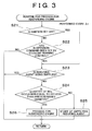
- the control of the third preferred embodiment is shown by a flow chart in Fig.3.
- An example shown in Fig. 3 is an example that the reducing agent is supplied as the recovery process, and the process is repeatedly performed every short time ⁇ t.
- whether or not the stop command of the engine 1 has been set is determined by whether the ignition (IG) key is off (step S21), and by whether the suspension command by "Economy Running Control" has been set (step S22).
- steps of S21 and S22 are the determination steps similar to the steps S1 and S2 shown in Fig.1.
- step S23 whether the reducing agent is being supplied is determined. That is, whether the recovery process of the catalyst is being performed is determined. This determination is similar to the determination at the step S3 shown in Fig.1. In the case that the determination at this step S23 is YES, the ECU proceeds to RETURN without performing any control. That is, even if the stop command of the engine 1 has been set, the engine 1 is not stopped immediately.
- the quantity of NOx occlusion means quantity of NOx occluded in the catalyst. If the quantity of NOx occlusion is equal to or less than the predetermined value, it means the condition that the NOx purification capability of the catalyst is well below the limit. Inversely, in case that the quantity of NOx occlusion is more than the predetermined value, it means the condition that the catalyst has almost no capacity to occlude NOx and that the purification capability is nearly in the saturation. Moreover, the determination of the quantity of NOx occlusion by the catalyst can be performed, aforementioned, based on the integrated values of the fuel supply quantity or the fuel injection quantity and the integrated value of the fuel supply time.
- the supply of the reducing agent is started (step S25). That is, the recovery process of the catalyst is performed.
- the determination at the step S23 is YES because the reducing agent is being supplied, and ECU proceeds to RETURN. Therefore, the supply of the reducing agent is continued without stopping the engine 1.
- the determination at step S23 is NO.
- the determination at step S24 is YES, in that case, ECU proceeds to step S26 and the stop process of the engine 1 is performed.
- the recovery of the purification capability that is, the deoxidization of the occluded nitrogen is performed at the high catalyst temperature
- the recovery of the purification capability of the catalyst can be performed sufficiently and rapidly.
- the NOx occlusion capacity of the catalyst can be sufficiently heightened when restarting the engine 1.
- the occlusion in the present invention includes holding in the catalyst by an absorption, a suction etc.
- “Stop” includes “suspend” and “suspension”.
- this invention is not limited by the preferred embodiments.
- An exhaust purification device in this invention can be replaced by a device with the necessity of performing the recovery process such as a device having an oxidization catalyst and/or a filter. Therefore, the recovery process in this invention is not limited to the supply of the reducing agent in the embodiments.
- the controllers are implemented with general purpose processors. It will be appreciated by those skilled in the art that the controllers can be implemented using a single special purpose integrated circuit (e.g., ASIC) having a main or central processor section for overall, system-level control, and separate sections dedicated to performing various different specific computations, functions and other processes under control of the central processor section.
- the controllers can be a plurality of separate dedicated or programmable integrated or other electronic circuits or devices (e.g., hardwired electronic or logic circuits such as discrete element circuits, or programmable logic devices such as PLDs, PLAs, PALs or the like).
- the controllers can be suitably programmed for use with a general purpose computer, e.g., a microprocessor, microcontroller or other processor device (CPU or MPU), either alone or in conjunction with one or more peripheral (e.g., integrated circuit) data and signal processing devices.
- a general purpose computer e.g., a microprocessor, microcontroller or other processor device (CPU or MPU)
- CPU or MPU processor device
- peripheral e.g., integrated circuit
- any device or assembly of devices on which a finite state machine capable of implementing the procedures described herein can be used as the controllers.
- a distributed processing architecture can be used for maximum data/signal processing capability and speed.
- a control device of an internal combustion engine (1) which is equipped with an exhaust system including an exhaust purification device (11) purifying exhaust gas, and which performs a recovery process for recovering purification capability of the exhaust purification device (11) in operation, is provided with a first means (S3, S4) for determining a state of performing the recovery process, a second means (S1, S2) for determining a stop demand for stopping the internal combustion engine (S1, S2), and a third means (S3, S4) for delaying the stop of the internal combustion engine (1) based on the stop demand according to result of the determination of the first means (S3, S4).
Landscapes
- Engineering & Computer Science (AREA)
- Chemical & Material Sciences (AREA)
- Combustion & Propulsion (AREA)
- Mechanical Engineering (AREA)
- General Engineering & Computer Science (AREA)
- Exhaust Gas After Treatment (AREA)
- Control Of Vehicle Engines Or Engines For Specific Uses (AREA)
- Output Control And Ontrol Of Special Type Engine (AREA)
- Exhaust Gas Treatment By Means Of Catalyst (AREA)
Abstract
Description
- This invention relates to a control device and method of an internal combustion engine such as a diesel engine. Especially, the invention relates to the control device and method of the internal combustion engine equipped with an exhaust system including an exhaust purification device which needs to perform a recovery process to recover purification capability, and the control method.
- An internal combustion engine such as a diesel engine outputs power by combusting fuel, so that the engine inevitably generates exhaust gas, however, from the viewpoint of preservation of the global environment, it is required to purify the exhaust gas generated from the internal combustion engine quickly. An example of so-called contaminated substances contained in the exhaust gas of the internal combustion engine is particulate matter (PM) such as hydrocarbon or smoke and nitrogen oxide (NOx). It is required to reduce the discharge quantity.
- The quantity of these substances in the exhaust gas can be reduced by controlling an operation condition of the internal combustion engine such as air-fuel ratio and fuel injection timing or an exhaust recirculation quantity reintroducing part of exhaust gas into an intake side. However, in these days, as requirement for preservation of the environment is becoming stronger, the restriction on the exhaust gas of the internal combustion engine is becoming more rigorous, therefore, improvement of the operation condition of the internal combustion engine cannot satisfy a new restriction on the exhaust gas.
- Now, in these days, an exhaust system of the internal combustion engine is equipped with an exhaust purification device, and is structured to transform so-called contaminated substances generated from the internal combustion engine into harmless substances and to release them into the air. Among the examples of the exhaust purification device is the catalyst and is structured so that contaminated substances in the exhaust gas are oxidized or deoxidized through the catalyst.
- Such purification reaction through the catalyst induces most efficiently when the catalyst is in an activated condition. Therefore, for instance, a device disclosed in a Japanese Patent Laid-Open Publication No.2000-97063 is structured to prohibit suspending an engine even if the engine is in idling when catalyst temperature is equal to or lower than a predetermined temperature. This is to raise the catalyst temperature rapidly by a continuous engine operation.
- Catalyst, in general, functions to promote reactions such as oxidization, and does not transform in itself, therefore, the continuous engine operation promotes the raise of the catalyst temperature by heat brought from the engine and by heat generated by the reaction through the catalyst. Moreover, an occlusion-deoxidization type catalyst purifying NOx is known as an exhaust purification catalyst, and as this type of catalyst occludes the contaminated substances such as NOx temporarily, a purification capability saturates according as an occlusion quantity reaches saturation. That is, as some types of the exhaust purification catalyst gradually deteriorates the purification capability by the continuous engine operation, above-mentioned, when the engine continues to be operated even if in idling, the occlusion quantity (purification capability) reaches saturation early.
- Moreover, the device disclosed in the publication presupposes suspending the engine in idling. The reason is that the device of the publication is subject to a hybrid vehicle and that the device restricts lowering of fuel consumption resulting from an unnecessary engine operation. The control for forcibly suspending the engine in idling is performed not only over the hybrid vehicle, and such control for suspending the engine is often named "Economy Running Control." This is the control to suspend the engine, for instance, in case that a vehicle stops at a stoplight and that a predetermined condition is satisfied.
- In case that the hybrid vehicle disclosed in the publication and the vehicle performing the Economy Running Control are loaded with the occlusion-deoxidization type catalyst, the occlusion quantity of the catalyst does not increase because of generating no exhaust gas while the engine is in suspension. However, the recovery process for reducing the occlusion quantity is not performed, either. The recovery process is a process to supply a reducing agent such as, e.g., fuel into the catalyst and to deoxidize nitrate nitrogen occluded in the catalyst and change it into nitrogen gas, and as occluded nitrogen is released, the purification capability of the catalyst is recovered. Though the reducing agent is supplied into the exhaust gas when the engine suspends during such recovery process, the reducing agent does not reach the catalyst and is consumed in vain, or unused reducing agent causes problems such as temporary increase of HC (hydrocarbon) emission quantity. Moreover, when the engine suspends just before performing the recovery process, in next drive, the occlusion quantity of the catalyst is almost in saturation and the catalyst temperature is in low, therefore, it is possible that NOx cannot be purified.
- An object of the invention is to provide the control device which enables to perform with mutually adjusting the suspension control of the internal combustion engine and the recovery process of the catalyst appropriately.
- The invention provides a control device and method of an internal combustion engine reserving temporarily a control based on a stop demand of the internal combustion engine, in case that both the stop demand of the internal combustion engine and a recovery control of an exhaust purification device are simultaneously set.
- A first aspect of the present invention relates to the control device of the internal combustion engine which is equipped with an exhaust system including the exhaust purification device purifying exhaust gas, and which performs the recovery process to recover purification capability of the exhaust purification device in operation of the internal combustion engine. This device includes a first means for determining whether the need for recovery for recovering the purification capability of the exhaust purification device is present, a second means for determining whether the stop demand for stopping the internal combustion engine is present, and a third means for giving priority to the recovery process based on the need for recovery in case that both the need for recovery and the stop demand is present.
- In the first aspect of the present invention, it is determined whether the need for recovery for recovering the purification capability of the exhaust purification device is present, moreover, it is determined whether the stop demand for stopping the internal combustion engine is present. When the need for recovery has been eliminated, the internal combustion engine is stopped. In case that both the need for recovery and the stop demand is present, the recovery process based on the need for recovery is given priority. Therefore, there is a case that the operation is continued without an immediate stop of the internal combustion engine even if the stop demand of the internal combustion engine is present, the recovery process of the exhaust purification device is performed during the operation, and the purification capability can be recovered. Moreover, problems such as an interruption of the recovery process and ineffectiveness caused by the interruption can be previously prevented.
- The third means may stop the internal combustion engine based on the stop demand, after it is determined that the need for recovery has been eliminated.
- The first means determines the state of performing the recovery process, and the third means may delay the stop of the internal combustion engine based on the stop demand according to the result of the determination of the first means.
- Therefore, the state of performing the recovery process of the purification capability of the exhaust purification device is determined, the stop control of the internal combustion engine is delayed based on the content of the determination. For that reason, there is a case that the operation is continued without the immediate stop of the internal combustion engine even if the stop demand of the internal combustion engine is present, the recovery process of the exhaust purification device is performed during the operation, and the purification capability can be recovered. Moreover, problems such as an interruption of the recovery process and ineffectiveness caused by the interruption can be previously prevented.
- Moreover, the first means determines whether the recovery process is performed, and the third means may delay the stop of the internal combustion engine based on the stop demand until the recovery process is terminated.
- Thus, in the state that the recovery process of the exhaust purification device is being performed, the internal combustion engine is not stopped even if the stop demand of the internal combustion engine is present, and the operation of the internal combustion engine is continued until the recovery process is terminated. For that reason, problems such that the temporarily started recovery process becomes ineffective without completing the process, and that the processing agent results in deterioration of the exhaust gas in case that some processing agent is used for the recovery process, can be previously avoided.
- Furthermore, the first means determines whether the recovery process is started within a predetermined time from when it is determined that the stop demand for stopping the internal combustion engine is present, and the third means may delay the stop of the internal combustion engine based on the stop demand until the recovery process is terminated.
- Thus, in case that the recovery process is performed within the predetermined time, that is, in case that it is expected that the recovery process is performed within relatively short time, the internal combustion engine is not stopped even if the stop demand of the internal combustion engine is present, and the operation of the internal combustion engine is continued until the recovery process is terminated. For that reason, at the time when the internal combustion engine is stopped, the purification capability of the exhaust purification device has been recovered, therefore, a processing capability of the exhaust purification device can be maintained to be sufficiently high when restarting the internal combustion engine.
- The third means may stop the internal combustion engine based on the stop demand after the recovery process has been performed.
- Thus, in case that the internal combustion engine is stopped, prior to that, the recovery process of the purification capability of the exhaust purification device is performed. Therefore, when restarting the internal combustion engine, the process capability of the exhaust purification device can be maintained to be sufficiently high. Moreover, as the recovery process is performed in the condition that the operation of the internal combustion engine is being continued, the recovery process can be performed efficiently and rapidly.
- Moreover, the first means determines the level of a requirement performing the recovery process, and determines whether the need for recovery is present based on the level of the requirement. The third means may stop the internal combustion engine after the recovery process is terminated based on the need for recovery .
- Thus, in case that the recovery process is performed prior to the stop of the internal combustion engine, the level of the requirement of the recovery process at that time is determined, and the recovery process is performed based on the determination result. In other words, in case that the level of the requirement of the recovery process is low, the internal combustion engine is stopped without the recovery process being performed, and inversely, in case that the level of the requirement of the recovery process is high, the internal combustion engine is stopped after the recovery process has been performed. As the result, the purification capability of the exhaust purification device can be maintained to be sufficiently high when restarting the internal combustion engine without the excessive number of performances of the recovery process.
- The exhaust purification device occludes NOx, and the purification capability may be capability to occlude the NOx.
- The recovery process may be a process to remove NOx occluded in the exhaust purification device.
- A second aspect in the present invention relates to the control method of the internal combustion engine which is equipped with the exhaust system including the exhaust purification device purifying the exhaust gas and which performs the recovery process to recover the purification capability of the exhaust purification device in operation of the internal combustion engine. This method includes the first step determining whether the need for recovery for recovering the purification capability of the exhaust purification device is present, the second step determining whether the stop demand for stopping the internal combustion engine is present, and the third step of stopping the internal combustion engine based on the stop demand determined at the second step when that the need for recovery has been eliminated is determined at the first step.
- At the first step, the need for recovery may be present thourhout the recovery process is being performed, and at the third step, the internal combustion engine may be stopped after the recovery process is terminated.
- On the basis whether the requirement for performing the recovery process is present, it may be determined whether the need for recovery is present at the first step. In that case, the control method may include the fourth step to start the recovery process based on the need for recovery , and may stop the internal combustion engine after the recovery process is terminated at the third step.
- At the first step, based on the fuel supply quantity into the internal combustion engine after the last recovery process has been performed, it may be determined whether the requirement for performing the recovery process is present.
- The exhaust purification device may occlude NOx, and it may be determined whether the quantity of NOx occlusion is more than the predetermined value at the first step, and when it is determined that the quantity of NOx occlusion is more than the predetermined value, it may be determined that the need for recovery is present.
- The forgoing and further objects, features and advantages of the invention will become apparent from the following description of preferred embodiments with reference to the accompanying drawings, wherein like numerals are used to represent like elements and wherein:
- Fig. 1 is a flow chart showing an example of control by a control device according to the first preferred embodiment.
- Fig. 2 is a flow chart showing an example of control by a control device according to the second preferred embodiment.
- Fig. 3 is a flow chart showing an example of control by a control device according to the third preferred embodiment.
- Fig. 4 is a view schematically showing an example of power system of a vehicle on which the internal combustion engine is mounted.
- Next, this invention will be explained based on preferred embodiments. An internal combustion engine according to this invention includes a power device which outputs power by combusting fuel such as a diesel engine and a gasoline engine, and an example is the internal combustion engine which is mounted on a vehicle and is used as a power source mainly for running. Fig. 4 schematically shows an example of use of a direct injection type diesel engine 1 (hereinafter, refer to simply as an engine) as the power source of the vehicle in the first through the third preferred embodiments. This
engine 1 is the internal combustion engine to directly inject fuel into the inside of a cylinder, and is equipped with a common-rail type electronic controlfuel injection system 2 to enable fuel injection at high pressure. One of the publicly known structure can be used for this electronic controlfuel injection system 2. - Moreover, the
engine 1 shown in Fig.4 is equipped with an exhaust turbine type supercharged engine i.e.turbocharger 3. An intake pipe 6 interposing anair cleaner 5 is connected with an air intake of acompressor 4, and anintake manifold 8 is connected with a delivery hole of thecompressor 4 through anintercooler 7 to drop an intake temperature. - Moreover, an exhaust manifold 9 which is communicatively connected with each cylinder is connected with an inflow hole of a turbine 10 in the
turbocharger 3. Furthermore, acatalyst converter 11 equipped with an exhaust purification catalyst is connected with an outlet of the turbine 10. At an upper side of thiscatalyst converter 11, an air-fuel ratio sensor 12 and apressure sensor 13 which detects pressure of an exhaust gas flowing in thecatalyst converter 11, are placed. Furthermore, atemperature sensor 14 for detecting the catalyst temperature is placed. This route from the exhaust manifold 9 to an opening (not shown) to the atmosphere through thecatalyst converter 11 is an exhaust route. - Moreover, herein, the exhaust purification catalyst is explained. The exhaust purification catalyst shown in Fig.4 is an NOx occlusion-deoxidization type catalyst. This has functions to occlude NOx which is one of the contaminated substances in the exhaust gas in an oxidized atmosphere, in the form of nitrate nitrogen, to deoxidize the occluded nitrate nitrogen in a deoxidized atmosphere and change it into nitrogen gas and to release it. Furthermore, as an activated oxygen is generated in the occlusion and in the deoxidization of NOx, the exhaust purification catalyst has functions to oxidize soot (PM: micro particle discharge) adhering to a surface of the catalyst and to remove it by the activated oxygen and the oxygen in the exhaust gas. Therefore, it is necessary to change the atmosphere of this exhaust purification catalyst into the oxidized atmosphere and the deoxidized atmosphere every predetermined time. The
engine 1 is structured to perform such changes of atmospheres by switching over an air-fuel ratio to an air excessive lean air-fuel ratio (an air-fuel ratio larger than a theoretical air-fuel ratio) and to a rich air-fuel ratio to be relatively increased fuel quantity (an air-fuel ratio less than the theoretical air-fuel ratio). Moreover, the control to increase the air-fuel ratio to release nitrogenous substance from the exhaust purification catalyst may be temporary, and such temporary increase of the air-fuel ratio is named "Rich Spike," which is an example of the control equivalent to "recovery process." - Furthermore, the
engine 1 shown in Fig.4 is equipped with an exhaust recirculation device to reduce NOx in the exhaust gas. That is, the exhaust manifold 9 and theintake manifold 8 are connected via anEGR cooler 15 cooling the exhaust gas recirculated and anEGR valve 16 performing the control of initiation and termination of recirculation and the control maintaining a fixed recirculation ratio (EGR ratio). - A continuously variable transmission 17 (CVT) is connected with the
engine 1 output side. The point is that thisCVT 17 is a transmission to enable to change a shift ratio continuously, and any other type, such as a belt type CVT and a traction type (troydal type) CVT can be adopted. - An electronic control unit for the engine (E-ECU) 18 to electrically control a fuel injection quantity, the injection timing, the initiation and the termination of the exhaust recirculation, and an opening of a throttle valve (not shown) in the
engine 1, and an electronic control unit for the transmission (T-ECU) 19 controlling theCVT 17 are equipped. TheseECUs engine 1 or a variable speed ratio of the CVT 17 (that is, ratio of engine speed and output rotation speed to wheel side) based on a required output amount shown by a throttle valve opening, a speed of a vehicle, an engine cooling water temperature, an oil temperature of theCVT 17, detection signals of eachsensor - At this point, explaining an automatic suspension and restarting of the
engine 1, this control is named so-called "Economy Running Control," and it is the control to prevent theengine 1 from the unnecessary operation and to improve fuel consumption. That is, in case that the vehicle temporarily stops, theengine 1 is automatically suspended under the conditions that the engine cooling water temperature is high, and that the brake pedal is depressed, and that an electric power to drive a starter motor is sufficiently charged, and theengine 1 is automatically restarted based on the detection of preliminary operation for moving the vehicle. - The
engine 1 injects the fuel to the inside of each cylinder and combusts it, and outputs mechanical energy generated by the combustion as a driving force. The quantity of the fuel consumed by the combustion is controlled to small quantity as possible within the limit satisfying the required output amount. Moreover, the contaminated substances such as NOx generated by fuel combustion in the cylinder are occluded in the catalyst in thecatalyst converter 11, the fuel quantity in the exhaust gas is increased and the atmosphere is changed into the deoxidized atmosphere before the occlusion quantity saturates, and nitrate nitrogen occluded in the catalyst is deoxidized and is released as nitrogen gas. That is, the recovery process for recovering the purification capability of the catalyst is performed. In this case, the fuel is equivalent to a reducing agent to change the catalyst into the deoxidized atmosphere. Moreover, the reducing agent may be injected to the inside of the cylinder to decrease the air-fuel ratio, or may be supplied by injecting into the exhaust gas. - The
engine 1, basically, is controlled to minimize the fuel consumption according to a required driving amount. Briefly explaining an example of the control, a target driving force is calculated based on the throttle valve opening representing the required driving amount and the speed of the vehicle, and a target output is calculated based on the target driving force and the speed of the vehicle. A target engine revolution is calculated based on the target output. These may be performed, for instance, by previously calculating the engine revolution to minimize the fuel consumption to each output, preparing this as a map, and calculating the target engine revolution from the target output and the map. And the various speed ratio of theCVT 17 is controlled to achieve the target engine revolution and the target output. - On the other hand, a target engine torque is calculated based on the target output and engine revolution. And the engine load (concretely, the throttle opening or the fuel injection quantity) is controlled to output the target engine torque.
- NOx is generated by fuel combustion in the
engine 1, and the NOx is occluded by the occlusion-deoxidization type catalyst provided the exhaust system. As the occlusion quantity of NOx by the catalyst increases by thecontinuous engine 1 operation, the nitrate nitrogen occluded in the catalyst is deoxidized and is changed into nitrogen gas, and is released into the open air, by supplying the reducing agent every predetermined time and changing into the deoxidized atmosphere, that is, by performing the Rich Spike equivalent the recovery process. - This Rich Spike is performed, for instance, in case that the integrated value of the fuel injection time reaches a standard value established previously. That is, the quantity of NOx generated in the
engine 1 correlates with the operation condition such as the engine load and the engine revolution, and the quantity of NOx occlusion correlates with the concentration of NOx discharged from theengine 1 and the continuation time, so that the NOx quantity can be integrated by integrating the fuel injection quantity and the time. Therefore, the timing performing the Rich Spike can be determined by integrating the fuel injection time of each operation condition of theengine 1. - In addition, the quantity of the particulate matter (PM) such as soot decreases at a high load side with low air-fuel ratio. That is, the particulate matter and NOx have a relationship that, when the operation condition of the
engine 1 is changed to reduce one discharge quantity, the other discharge quantity increases, and each quantity has some correlation. Therefore, the NOx discharge quantity can be calculated based on the integrated values of the fuel injection quantity and the continuation time, and the discharge quantity of the particulate matter can be also calculated. - The NOx occlusion in the catalyst and an accumulation of particulate matter increase according to the operation time of the
engine 1, so that the level of the performing the recovery process varies according to the operation condition of theengine 1. As the recovery process is performed by increasing the quantity of the reducing agent in the exhaust gas, the premise that theengine 1 is in operation is required. On the other hand, the stop command of theengine 1 is induced by a driver's turning off the ignition key or by the suspension command at "Economy Running Control". So, the control device of the preferred embodiment of the present invention is so configured as to perform the following control to mutually adapt the recovery process of the catalyst and the stop command of theengine 1. - Fig. 1 is a flow chart explaining the control of the first preferred embodiment, and the control is repeatedly performed every predetermined short time Δt. First, as the determination whether or not the stop command has been set, whether the ignition (IG) key is off is determined (step S1). And, whether or not the suspension command of the
engine 1 by the "Economy Running Control" has been set is determined (step S2). Either determination at steps S1 and S2 can be performed first. In case that the determinations at steps S1 and S2 are both NO, this means no stop command (the stop command at step S1 and the suspension command) of theengine 1, so that ECU proceeds to RETURN without performing any control. - On the other hand, in the case that either determination at step S1 or step S2 isYES, that is, in the case that the stop command of the
engine 1 has been set, whether the reducing agent is being supplied is determined (step S3). Concretely, whether the Rich Spike is being performed, or whether the fuel injection into the exhaust gas, so-called post injection, is being performed, so-called whether the recovery process of the catalyst is being performed, are determined. - In the case that the determination at step S3 is YES as the recovery process of the catalyst is being performed, ECU proceeds to RETURN. After that, when time passes and the supply of the reducing agent is terminated, the determination at step S3 is NO, and the stop process of the
engine 1 is performed based on the result of the determination of step S3 (step S4). That is, if the recovery process of the catalyst is being performed though the stop command has been set, the stop control of theengine 1 based on the stop command is not performed immediately, and the stop process of the engine is delayed until the recovery process is terminated. - Therefore, as the
engine 1 is not stopped while the reducing agent is being supplied, the control shown in Fig.1 can previously avoid problems such that the recovery of the purification capability of the catalyst become insufficient, that the supplied reducing agent (fuel) is wasted, moreover, that the quantity of HC so-called contaminated substances in the exhaust gas increases resulting from the reducing agent. Furthermore, when restarting theengine 1, the purification capability of the catalyst can be maintained to be sufficiently high. - Moreover, the control can be structured to delay the stop process of the
engine 1 in case that the supply of the reducing agent is expected within a predetermined time. The second preferred embodiment for performing the control is shown by a flow chart in Fig.2, and an example shown there, is structured to determine whether the supply of the reducing agent is performed within the predetermined time (step S31) in case that the determination at step S3 shown in Fig. 1 is NO. - Like aforementioned, the generation quantity of NOx and soot so-called contaminated substances is quantity according to a fuel combustion quantity, a combustion condition or a fuel injection time, so that the time needed until the purification capability of the catalyst saturates can be calculated based on the integrated values such as the fuel supply quantity, the injection quantity, or injection time measured after the last recovery process of the catalyst is terminated. Therefore, the determination at step S31 can be performed based on the integrated values.
- Furthermore, in case that the determination at the step S31 is YES, that is, in case that the supply of the reducing agent (the recovery process) is expected within the predetermined time from when the stop command to the
engine 1 at S1 and S2 has been set is determined, ECU proceeds to RETURN. On the other hand, in case that the determination at step S31 is NO, that is, in case that the reducing agent is not supplied within the predetermined time (in case that the recovery process is not expected), ECU proceeds to step S4, and the stop process of theengine 1 is performed. - That is, in the control shown in Fig.2, not only while the reducing agent is being supplied, in case that the supply of the reducing agent is expected within the predetermined time, that is, in case that the recovery process of the catalyst is performed within the predetermined time, the stop process of the
engine 1 based on the stop command of theengine 1 is delayed. Therefore, the situation such that theengine 1 is stopped in the condition that the purification capability of the catalyst is almost saturated, and that the purification capability of the catalyst is in low when restarting theengine 1, can be previously prevented. Moreover, as the recovery process of the catalyst is performed in the condition that theengine 1 is continuously being operated, in the recovery process of the catalyst, that is, in the example, the deoxidization of the occluded nitrate nitrogen can be performed efficiently and sufficiently as needed. - Furthermore, in case that the stop command of the
engine 1 has been set, the control device of the third preferred embodiment in the present invention can be configured to stop theengine 1 after the recovery process of the purification capability of the exhaust purification device is performed. The control of the third preferred embodiment is shown by a flow chart in Fig.3. An example shown in Fig. 3 is an example that the reducing agent is supplied as the recovery process, and the process is repeatedly performed every short time Δt. In this example shown in Fig.3 as well as in the example shown in Fig.1, whether or not the stop command of theengine 1 has been set is determined by whether the ignition (IG) key is off (step S21), and by whether the suspension command by "Economy Running Control" has been set (step S22). These steps of S21 and S22 are the determination steps similar to the steps S1 and S2 shown in Fig.1. - In case that the stop command of the
engine 1 has been set, that is, in case that the determinations at step S21 or S22 are YES, whether the reducing agent is being supplied is determined (step S23). That is, whether the recovery process of the catalyst is being performed is determined. This determination is similar to the determination at the step S3 shown in Fig.1. In the case that the determination at this step S23 is YES, the ECU proceeds to RETURN without performing any control. That is, even if the stop command of theengine 1 has been set, theengine 1 is not stopped immediately. - On the other hand, in case that the determination at step S23 is NO because the reducing agent is not being supplied, whether the quantity of NOx occlusion is equal to or less than a predetermined quantity is determined (step S24). In this case, the quantity of NOx occlusion means quantity of NOx occluded in the catalyst. If the quantity of NOx occlusion is equal to or less than the predetermined value, it means the condition that the NOx purification capability of the catalyst is well below the limit. Inversely, in case that the quantity of NOx occlusion is more than the predetermined value, it means the condition that the catalyst has almost no capacity to occlude NOx and that the purification capability is nearly in the saturation. Moreover, the determination of the quantity of NOx occlusion by the catalyst can be performed, aforementioned, based on the integrated values of the fuel supply quantity or the fuel injection quantity and the integrated value of the fuel supply time.
- In case that the determination at the step S24 is NO, that is, in case that the quantity of NOx occlusion is more than the predetermined value and that the catalyst has no capacity to occlude NOx and that the level of the recovery process is high, the supply of the reducing agent is started (step S25). That is, the recovery process of the catalyst is performed. After that, when the determination at the step S23 is performed, the determination at the step S23 is YES because the reducing agent is being supplied, and ECU proceeds to RETURN. Therefore, the supply of the reducing agent is continued without stopping the
engine 1. - As the supply of the reducing agent is terminated when time passes more, the determination at step S23 is NO. In that case, as the recovery process of the catalyst is completed by the termination of the supply of the reducing agent, the quantity of NOx occlusion comes back to equal to or less than the predetermined quantity and the level of the requirement of the recovery process is in low. As the result, as the determination at step S24 is YES, in that case, ECU proceeds to step S26 and the stop process of the
engine 1 is performed. - In this way, in the example shown in Fig.3, in case that the stop command of the
engine 1 has been set, even if the recovery process of the catalyst has not performed by that time, theengine 1 is stopped after the recovery process of the catalyst is performed. And especially, in the example of the control shown in Fig.3, even if the purification capability of the catalyst has not reached saturation, if the condition is just before reaching saturation, as the stop command of theengine 1 has been set, the recovery process of the catalyst is performed before the purification capability reaches saturation, and theengine 1 is stopped after the recovery process is terminated. - Therefore, according to the control shown in Fig.3, after the recovery process of the catalyst, concretely, the supply of the reducing agent is terminated and the NOx occlusion capacity of the catalyst is recovered, the
engine 1 is stopped. Accordingly, problems such that the reducing agent (fuel) is wasted due to simultaneous occurrence of supply of the of the reducing agent and the stop of theengine 1, moreover, and that the reducing agent causes the increase of the quantity of so-called contaminated substances such as HC in the exhaust gas, can be previously avoided. And, as the supply of the reducing agent is terminated and the purification capability of the catalyst is recovered in the condition that the operation of theengine 1 is being continued, the recovery of the purification capability, that is, the deoxidization of the occluded nitrogen is performed at the high catalyst temperature, the recovery of the purification capability of the catalyst can be performed sufficiently and rapidly. As the result, the NOx occlusion capacity of the catalyst can be sufficiently heightened when restarting theengine 1. - Here, explaining a relationship between the each preferred embodiment and this invention, functional means at steps S3, S31, S23, and S24 can be regarded as a first means, the functional means at steps S1, S2, S21, and S22 can be regarded as a second means, and the functional means to proceed to RETURN in case that the determination at step S3 or step S31 is YES, and steps S4 and S26 can be regarded as a third means.
- Moreover, the occlusion in the present invention includes holding in the catalyst by an absorption, a suction etc.
- "Stop" includes "suspend" and "suspension".
- Meanwhile, in the preferred embodiments, though the engine equipped with the exhaust system including the catalyst converter with the occlusion-deoxidization type catalyst of NOx has been explained, this invention is not limited by the preferred embodiments. An exhaust purification device in this invention can be replaced by a device with the necessity of performing the recovery process such as a device having an oxidization catalyst and/or a filter. Therefore, the recovery process in this invention is not limited to the supply of the reducing agent in the embodiments.
- In the illustrated embodiment, the controllers are implemented with general purpose processors. It will be appreciated by those skilled in the art that the controllers can be implemented using a single special purpose integrated circuit (e.g., ASIC) having a main or central processor section for overall, system-level control, and separate sections dedicated to performing various different specific computations, functions and other processes under control of the central processor section. The controllers can be a plurality of separate dedicated or programmable integrated or other electronic circuits or devices (e.g., hardwired electronic or logic circuits such as discrete element circuits, or programmable logic devices such as PLDs, PLAs, PALs or the like). The controllers can be suitably programmed for use with a general purpose computer, e.g., a microprocessor, microcontroller or other processor device (CPU or MPU), either alone or in conjunction with one or more peripheral (e.g., integrated circuit) data and signal processing devices. In general, any device or assembly of devices on which a finite state machine capable of implementing the procedures described herein can be used as the controllers. A distributed processing architecture can be used for maximum data/signal processing capability and speed.
- A control device of an internal combustion engine (1) which is equipped with an exhaust system including an exhaust purification device (11) purifying exhaust gas, and which performs a recovery process for recovering purification capability of the exhaust purification device (11) in operation, is provided with a first means (S3, S4) for determining a state of performing the recovery process, a second means (S1, S2) for determining a stop demand for stopping the internal combustion engine (S1, S2), and a third means (S3, S4) for delaying the stop of the internal combustion engine (1) based on the stop demand according to result of the determination of the first means (S3, S4).
Claims (14)
- A control device of an internal combustion engine which is equipped with an exhaust system including an exhaust purification device purifying an exhaust gas, and which performs a recovery process to recover purification capability of the exhaust purification device while the internal combustion engine is in operation, characterized by comprising:a first means for determining whether need for recovery to recover the purification capability of the exhaust purification device is present,a second means for determining whether a stop demand for stopping the internal combustion engine is present and,a third means for giving priority to the recovery process based on the need for recovery if the need for recovery and the stop demand is present.
- The control device according to claim 1, wherein the third means stops the internal combustion engine based on the stop demand, after the need for recovery is determined to have been eliminated.
- The control device according to claim 1 or 2, wherein the first means determines a state of performing recovery process and,
the third means delays the stop of the internal combustion engine based on the stop demand, according to result of the determination of the first means. - The control device according to claim 3, wherein the first means determines whether the recovery process is being performed and,
the third means delays the stop of the internal combustion engine based on the stop demand, until the recovery process is terminated. - The control device according to claim 3 or 4, wherein the first means determines whether the recovery process is initiated within a predetermined time after the stop demand for the internal combustion engine is determined and,
the third means delays the stop of the internal combustion engine based on the stop demand, until the recovery process is terminated. - The control device according to any one of claims 1 to 5, wherein the third means stops the internal combustion engine based on the stop demand, after the recovery process is terminated.
- The control device according to claim 6, wherein the first means determines a level of a requirement for performing the recovery process and determines whether the the need for recovery is present based on the level of the requirement and,
the third means stops the internal combustion engine based on the need for recovery, after the recovery process is terminated. - The control device according to any one of claims 1 to 7, wherein the exhaust purification device occludes NOx and,
the purification capability is capability to occlude the NOx. - The control device according to claim 8, wherein the NOx occluded in the exhaust purification device is removed through the recovery process.
- A control method of an internal combustion engine which is equipped with an exhaust system including an exhaust purification device purifying exhaust gas, and which performs a recovery process to recover purification capability of the exhaust purification device while the internal combustion engine is in operation, characterized by comprising:a first step of determining whether need for recovery for recovering the purification capability of the exhaust purification device is present,a second step of determining whether a stop demand for stopping the internal combustion engine is present,a third step of stopping the internal combustion engine based on the stop demand determined at the second step, if the need for recovery is determined to have been eliminated at the first step.
- The control method according to claim 10, wherein the need for recovery is present throughout the recovery process is being performed at the first step,
the internal combustion engine is stopped after the recovery process is terminated at the third step. - The control method according to claim 10 or 11, wherein it is determined whether the need for recovery is present at the first step, on the basis whether the requirement for performing the recovery process is present,
the control method further comprises a fourth step of initiating the recovery process based on the need for recovery and,
the internal combustion engine is stopped after the recovery process is terminated at the third step. - The control method according to any one of claims 10 to 12, wherein it is determined whether the requirement for performing the recovery process is present based on a quantity of fuel supply to the internal combustion engine after the last recovery process has been performed, at the first step.
- The control method according to any one of claims 10 to 13, wherein the exhaust purification device occludes NOx and,
it is determined whether a quantity of NOx occlusion is more than a predetermined value at the first step, and it is determined that the need for recovery is present if it is determined that the quantity of NOx occlusion is more than the predetermined value at the first step.
Applications Claiming Priority (2)
| Application Number | Priority Date | Filing Date | Title |
|---|---|---|---|
| JP2001226726 | 2001-07-26 | ||
| JP2001226726A JP4239443B2 (en) | 2001-07-26 | 2001-07-26 | Control device for internal combustion engine |
Publications (3)
| Publication Number | Publication Date |
|---|---|
| EP1279817A2 true EP1279817A2 (en) | 2003-01-29 |
| EP1279817A3 EP1279817A3 (en) | 2006-03-01 |
| EP1279817B1 EP1279817B1 (en) | 2011-06-08 |
Family
ID=19059495
Family Applications (1)
| Application Number | Title | Priority Date | Filing Date |
|---|---|---|---|
| EP02016639A Expired - Lifetime EP1279817B1 (en) | 2001-07-26 | 2002-07-25 | Control device and method of internal combustion engine |
Country Status (2)
| Country | Link |
|---|---|
| EP (1) | EP1279817B1 (en) |
| JP (1) | JP4239443B2 (en) |
Cited By (1)
| Publication number | Priority date | Publication date | Assignee | Title |
|---|---|---|---|---|
| EP2202401A3 (en) * | 2006-07-12 | 2010-08-18 | Toyota Jidosha Kabushiki Kaisha | Power source system of internal combustion engine |
Families Citing this family (3)
| Publication number | Priority date | Publication date | Assignee | Title |
|---|---|---|---|---|
| JP2013216223A (en) * | 2012-04-10 | 2013-10-24 | Toyota Motor Corp | Hybrid vehicle |
| JP2016205146A (en) * | 2015-04-15 | 2016-12-08 | 本田技研工業株式会社 | Exhaust gas purification device for internal combustion engine |
| JP6501065B2 (en) * | 2015-05-13 | 2019-04-17 | 三菱自動車工業株式会社 | Engine exhaust purification system |
Citations (2)
| Publication number | Priority date | Publication date | Assignee | Title |
|---|---|---|---|---|
| EP0869267A2 (en) | 1997-04-03 | 1998-10-07 | Toyota Jidosha Kabushiki Kaisha | An exhaust gas purification device for an internal combustion engine |
| US6220019B1 (en) | 1998-09-30 | 2001-04-24 | Honda Giken Kogyo Kabushiki Kaisha | Exhaust gas purifying apparatus for an internal combustion engine |
Family Cites Families (2)
| Publication number | Priority date | Publication date | Assignee | Title |
|---|---|---|---|---|
| DE19636790A1 (en) * | 1996-09-11 | 1998-03-12 | Volkswagen Ag | NOx emission control process |
| WO1998051919A1 (en) * | 1997-05-12 | 1998-11-19 | Toyota Jidosha Kabushiki Kaisha | Exhaust emission controlling apparatus of internal combustion engine |
-
2001
- 2001-07-26 JP JP2001226726A patent/JP4239443B2/en not_active Expired - Fee Related
-
2002
- 2002-07-25 EP EP02016639A patent/EP1279817B1/en not_active Expired - Lifetime
Patent Citations (2)
| Publication number | Priority date | Publication date | Assignee | Title |
|---|---|---|---|---|
| EP0869267A2 (en) | 1997-04-03 | 1998-10-07 | Toyota Jidosha Kabushiki Kaisha | An exhaust gas purification device for an internal combustion engine |
| US6220019B1 (en) | 1998-09-30 | 2001-04-24 | Honda Giken Kogyo Kabushiki Kaisha | Exhaust gas purifying apparatus for an internal combustion engine |
Cited By (2)
| Publication number | Priority date | Publication date | Assignee | Title |
|---|---|---|---|---|
| EP2202401A3 (en) * | 2006-07-12 | 2010-08-18 | Toyota Jidosha Kabushiki Kaisha | Power source system of internal combustion engine |
| US8151555B2 (en) | 2006-07-12 | 2012-04-10 | Toyota Jidosha Kabushiki Kaisha | Power source system of internal combustion engine |
Also Published As
| Publication number | Publication date |
|---|---|
| EP1279817B1 (en) | 2011-06-08 |
| EP1279817A3 (en) | 2006-03-01 |
| JP2003041968A (en) | 2003-02-13 |
| JP4239443B2 (en) | 2009-03-18 |
Similar Documents
| Publication | Publication Date | Title |
|---|---|---|
| JP3929296B2 (en) | Internal combustion engine | |
| EP1247968B1 (en) | Control apparatus and method for vehicle having internal combustion engine and continuously variable transmission, and control apparatus and method for internal combustion engine | |
| CN100510354C (en) | Operation stop control method for internal combustion engine of vehicle | |
| US7104051B2 (en) | Exhaust gas purification device | |
| JP4375483B2 (en) | Exhaust gas purification device for internal combustion engine | |
| US10364716B2 (en) | Exhaust gas control apparatus for internal combustion engine and exhaust gas control method for internal combustion engine | |
| CN100449128C (en) | Exhaust purification device and exhaust purification method for internal combustion engine | |
| JP4119927B2 (en) | Exhaust gas purification device for internal combustion engine | |
| US20040065076A1 (en) | Method of purifying exhaust gas of an internal combustion engine | |
| CN107448264B (en) | Exhaust purification device for internal combustion engine | |
| JP5338993B1 (en) | Exhaust gas purification device for internal combustion engine | |
| EP1536120B1 (en) | Exhaust gas control apparatus for internal combustion engine and control method thereof | |
| EP1279817B1 (en) | Control device and method of internal combustion engine | |
| EP1515014B1 (en) | Exhaust purifying apparatus of internal combustion engine | |
| JP3584798B2 (en) | Exhaust gas purification device for in-vehicle internal combustion engine | |
| JP4661013B2 (en) | Internal combustion engine | |
| JP2004285947A (en) | Exhaust purification device for internal combustion engine | |
| JP3613681B2 (en) | Control device for internal combustion engine | |
| JP2007187006A (en) | Exhaust gas purification device for internal combustion engine | |
| JP4357917B2 (en) | Exhaust gas purification device for internal combustion engine | |
| JP2018178866A (en) | Engine exhaust purification system | |
| JP2010106750A (en) | Exhaust emission control device for vehicle | |
| JP4062229B2 (en) | Exhaust gas purification device for internal combustion engine | |
| US20050245352A1 (en) | Method for operating an axhaust gas treatment device | |
| JP2006083776A (en) | Control device for internal combustion engine |
Legal Events
| Date | Code | Title | Description |
|---|---|---|---|
| PUAI | Public reference made under article 153(3) epc to a published international application that has entered the european phase |
Free format text: ORIGINAL CODE: 0009012 |
|
| 17P | Request for examination filed |
Effective date: 20020725 |
|
| AK | Designated contracting states |
Designated state(s): AT BE BG CH CY CZ DE DK EE ES FI FR GB GR IE IT LI LU MC NL PT SE SK TR |
|
| AX | Request for extension of the european patent |
Extension state: AL LT LV MK RO SI |
|
| PUAL | Search report despatched |
Free format text: ORIGINAL CODE: 0009013 |
|
| AK | Designated contracting states |
Kind code of ref document: A3 Designated state(s): AT BE BG CH CY CZ DE DK EE ES FI FR GB GR IE IT LI LU MC NL PT SE SK TR |
|
| AX | Request for extension of the european patent |
Extension state: AL LT LV MK RO SI |
|
| 17Q | First examination report despatched |
Effective date: 20060620 |
|
| AKX | Designation fees paid |
Designated state(s): DE FR IT |
|
| GRAP | Despatch of communication of intention to grant a patent |
Free format text: ORIGINAL CODE: EPIDOSNIGR1 |
|
| GRAS | Grant fee paid |
Free format text: ORIGINAL CODE: EPIDOSNIGR3 |
|
| GRAA | (expected) grant |
Free format text: ORIGINAL CODE: 0009210 |
|
| AK | Designated contracting states |
Kind code of ref document: B1 Designated state(s): DE FR IT |
|
| REG | Reference to a national code |
Ref country code: DE Ref legal event code: R096 Ref document number: 60240216 Country of ref document: DE Effective date: 20110721 |
|
| PLBE | No opposition filed within time limit |
Free format text: ORIGINAL CODE: 0009261 |
|
| STAA | Information on the status of an ep patent application or granted ep patent |
Free format text: STATUS: NO OPPOSITION FILED WITHIN TIME LIMIT |
|
| 26N | No opposition filed |
Effective date: 20120309 |
|
| REG | Reference to a national code |
Ref country code: DE Ref legal event code: R097 Ref document number: 60240216 Country of ref document: DE Effective date: 20120309 |
|
| REG | Reference to a national code |
Ref country code: DE Ref legal event code: R084 Ref document number: 60240216 Country of ref document: DE Effective date: 20130410 |
|
| REG | Reference to a national code |
Ref country code: FR Ref legal event code: PLFP Year of fee payment: 15 |
|
| REG | Reference to a national code |
Ref country code: FR Ref legal event code: PLFP Year of fee payment: 16 |
|
| REG | Reference to a national code |
Ref country code: FR Ref legal event code: PLFP Year of fee payment: 17 |
|
| PGFP | Annual fee paid to national office [announced via postgrant information from national office to epo] |
Ref country code: FR Payment date: 20210611 Year of fee payment: 20 Ref country code: IT Payment date: 20210610 Year of fee payment: 20 |
|
| PGFP | Annual fee paid to national office [announced via postgrant information from national office to epo] |
Ref country code: DE Payment date: 20210629 Year of fee payment: 20 |
|
| REG | Reference to a national code |
Ref country code: DE Ref legal event code: R071 Ref document number: 60240216 Country of ref document: DE |