EP1279812A2 - Intake air control devices for internal combustion engines - Google Patents
Intake air control devices for internal combustion engines Download PDFInfo
- Publication number
- EP1279812A2 EP1279812A2 EP02016321A EP02016321A EP1279812A2 EP 1279812 A2 EP1279812 A2 EP 1279812A2 EP 02016321 A EP02016321 A EP 02016321A EP 02016321 A EP02016321 A EP 02016321A EP 1279812 A2 EP1279812 A2 EP 1279812A2
- Authority
- EP
- European Patent Office
- Prior art keywords
- intake air
- orifice
- valve member
- air control
- control device
- Prior art date
- Legal status (The legal status is an assumption and is not a legal conclusion. Google has not performed a legal analysis and makes no representation as to the accuracy of the status listed.)
- Granted
Links
- 238000002485 combustion reaction Methods 0.000 title claims abstract description 20
- 238000011144 upstream manufacturing Methods 0.000 claims abstract description 10
- 230000003247 decreasing effect Effects 0.000 claims abstract description 4
- 230000007423 decrease Effects 0.000 description 9
- 239000012535 impurity Substances 0.000 description 8
- 230000008021 deposition Effects 0.000 description 6
- 238000010276 construction Methods 0.000 description 2
- 230000000694 effects Effects 0.000 description 2
- 238000004088 simulation Methods 0.000 description 2
- 230000000052 comparative effect Effects 0.000 description 1
- 230000001419 dependent effect Effects 0.000 description 1
- 238000005553 drilling Methods 0.000 description 1
- 238000000034 method Methods 0.000 description 1
- 239000000203 mixture Substances 0.000 description 1
- 238000004080 punching Methods 0.000 description 1
Images


Classifications
-
- F—MECHANICAL ENGINEERING; LIGHTING; HEATING; WEAPONS; BLASTING
- F02—COMBUSTION ENGINES; HOT-GAS OR COMBUSTION-PRODUCT ENGINE PLANTS
- F02M—SUPPLYING COMBUSTION ENGINES IN GENERAL WITH COMBUSTIBLE MIXTURES OR CONSTITUENTS THEREOF
- F02M35/00—Combustion-air cleaners, air intakes, intake silencers, or induction systems specially adapted for, or arranged on, internal-combustion engines
- F02M35/10—Air intakes; Induction systems
- F02M35/10006—Air intakes; Induction systems characterised by the position of elements of the air intake system in direction of the air intake flow, i.e. between ambient air inlet and supply to the combustion chamber
- F02M35/10078—Connections of intake systems to the engine
- F02M35/10085—Connections of intake systems to the engine having a connecting piece, e.g. a flange, between the engine and the air intake being foreseen with a throttle valve, fuel injector, mixture ducts or the like
-
- F—MECHANICAL ENGINEERING; LIGHTING; HEATING; WEAPONS; BLASTING
- F02—COMBUSTION ENGINES; HOT-GAS OR COMBUSTION-PRODUCT ENGINE PLANTS
- F02B—INTERNAL-COMBUSTION PISTON ENGINES; COMBUSTION ENGINES IN GENERAL
- F02B31/00—Modifying induction systems for imparting a rotation to the charge in the cylinder
- F02B31/04—Modifying induction systems for imparting a rotation to the charge in the cylinder by means within the induction channel, e.g. deflectors
- F02B31/06—Movable means, e.g. butterfly valves
-
- F—MECHANICAL ENGINEERING; LIGHTING; HEATING; WEAPONS; BLASTING
- F02—COMBUSTION ENGINES; HOT-GAS OR COMBUSTION-PRODUCT ENGINE PLANTS
- F02B—INTERNAL-COMBUSTION PISTON ENGINES; COMBUSTION ENGINES IN GENERAL
- F02B31/00—Modifying induction systems for imparting a rotation to the charge in the cylinder
- F02B31/08—Modifying induction systems for imparting a rotation to the charge in the cylinder having multiple air inlets
- F02B31/085—Modifying induction systems for imparting a rotation to the charge in the cylinder having multiple air inlets having two inlet valves
-
- F—MECHANICAL ENGINEERING; LIGHTING; HEATING; WEAPONS; BLASTING
- F02—COMBUSTION ENGINES; HOT-GAS OR COMBUSTION-PRODUCT ENGINE PLANTS
- F02D—CONTROLLING COMBUSTION ENGINES
- F02D9/00—Controlling engines by throttling air or fuel-and-air induction conduits or exhaust conduits
- F02D9/08—Throttle valves specially adapted therefor; Arrangements of such valves in conduits
- F02D9/10—Throttle valves specially adapted therefor; Arrangements of such valves in conduits having pivotally-mounted flaps
- F02D9/1005—Details of the flap
- F02D9/101—Special flap shapes, ribs, bores or the like
-
- F—MECHANICAL ENGINEERING; LIGHTING; HEATING; WEAPONS; BLASTING
- F02—COMBUSTION ENGINES; HOT-GAS OR COMBUSTION-PRODUCT ENGINE PLANTS
- F02D—CONTROLLING COMBUSTION ENGINES
- F02D9/00—Controlling engines by throttling air or fuel-and-air induction conduits or exhaust conduits
- F02D9/08—Throttle valves specially adapted therefor; Arrangements of such valves in conduits
- F02D9/10—Throttle valves specially adapted therefor; Arrangements of such valves in conduits having pivotally-mounted flaps
- F02D9/109—Throttle valves specially adapted therefor; Arrangements of such valves in conduits having pivotally-mounted flaps having two or more flaps
- F02D9/1095—Rotating on a common axis, e.g. having a common shaft
-
- F—MECHANICAL ENGINEERING; LIGHTING; HEATING; WEAPONS; BLASTING
- F02—COMBUSTION ENGINES; HOT-GAS OR COMBUSTION-PRODUCT ENGINE PLANTS
- F02M—SUPPLYING COMBUSTION ENGINES IN GENERAL WITH COMBUSTIBLE MIXTURES OR CONSTITUENTS THEREOF
- F02M35/00—Combustion-air cleaners, air intakes, intake silencers, or induction systems specially adapted for, or arranged on, internal-combustion engines
- F02M35/10—Air intakes; Induction systems
- F02M35/10242—Devices or means connected to or integrated into air intakes; Air intakes combined with other engine or vehicle parts
- F02M35/10255—Arrangements of valves; Multi-way valves
-
- F—MECHANICAL ENGINEERING; LIGHTING; HEATING; WEAPONS; BLASTING
- F02—COMBUSTION ENGINES; HOT-GAS OR COMBUSTION-PRODUCT ENGINE PLANTS
- F02M—SUPPLYING COMBUSTION ENGINES IN GENERAL WITH COMBUSTIBLE MIXTURES OR CONSTITUENTS THEREOF
- F02M35/00—Combustion-air cleaners, air intakes, intake silencers, or induction systems specially adapted for, or arranged on, internal-combustion engines
- F02M35/10—Air intakes; Induction systems
- F02M35/104—Intake manifolds
- F02M35/112—Intake manifolds for engines with cylinders all in one line
-
- Y—GENERAL TAGGING OF NEW TECHNOLOGICAL DEVELOPMENTS; GENERAL TAGGING OF CROSS-SECTIONAL TECHNOLOGIES SPANNING OVER SEVERAL SECTIONS OF THE IPC; TECHNICAL SUBJECTS COVERED BY FORMER USPC CROSS-REFERENCE ART COLLECTIONS [XRACs] AND DIGESTS
- Y02—TECHNOLOGIES OR APPLICATIONS FOR MITIGATION OR ADAPTATION AGAINST CLIMATE CHANGE
- Y02T—CLIMATE CHANGE MITIGATION TECHNOLOGIES RELATED TO TRANSPORTATION
- Y02T10/00—Road transport of goods or passengers
- Y02T10/10—Internal combustion engine [ICE] based vehicles
- Y02T10/12—Improving ICE efficiencies
Definitions
- the present invention relates to intake air control devices for internal combustion engines.
- FIG. 6 A cross-section of a known intake air control device is shown in FIG. 6.
- the known device includes a valve member 110 that opens and closes an intake air channel 103 of an internal combustion engine.
- a circular orifice 111 is defined within the valve member 110 and serves to generate a strong directional swirl of the suction air when the valve member 110 is fully closed.
- Japanese Laid-Open Utility Model Publication No. 1-118128 teaches such a known intake air control device.
- the circumferential wall 112 of the orifice 111 has a simple straight cylindrical configuration.
- the present inventors have performed several experiments in order to determine how the shape of the orifice 111 affects the flow of the air through the orifice 111. As a result, they found that the air flowing through the orifice 111 may stagnate if the circumferential wall 112 has a simple straight cylindrical configuration. Further, such stagnation may result in deposition of combustion products or impurities on the circumferential wall 112 of the orifice 111. When combustion products or impurities are deposited on the circumferential wall 112 of the orifice 111, the flow rate of the intake air through the orifice 111 may be reduced. In this case, the required air flow rates for the engine cannot be ensured in some cases.
- intake air control devices may be designed so as to minimize the deposition of combustion products or impurities on a circumferential wall of an orifice defined within a valve member.
- intake air control devices include a valve member rotatably disposed within an air intake channel of an internal combustion engine.
- the valve member may be operable to open and close the air intake channel.
- At least one orifice is defined within the valve member.
- the circumferential wall of the orifice preferably includes at least one wall portion that defines an open area.
- the cross-section (size) of the open area preferably decreases in the direction from an upstream side to a downstream side of the valve member.
- the flow rate of the intake air will increase.
- stagnation in the intake air that flows through the orifice may be minimized, thereby minimizing or eliminating the deposition of combustion products or impurities on the circumferential wall of the orifice.
- intake air control devices may include at least one valve member.
- the valve member is rotatably disposed within a corresponding air intake port that is formed in a valve body.
- the valve body is preferably arranged and constructed to be mounted on an internal combustion engine.
- the valve member may be operable to open and close the air intake port.
- At least one orifice may be defined within the valve member.
- the orifice preferably includes a circumferential wall having at least one wall portion that defines an open area (opening).
- the cross-section (size) of the open area (opening) preferably decreases in the direction from an upstream side to a downstream side of the valve member.
- the flow rate of the intake air will increase.
- stagnation in the intake air that flows through the orifice may be minimized to consequently minimize the deposition of combustion products or impurities on the circumferential wall of the orifice.
- the wall portion may define a linear inclined or beveled surface as viewed in a cross-sectional view along an axis of the orifice.
- the wall portion may define a convexly curved surface as viewed in a cross-sectional view along an axis of the orifice.
- a first representative intake air control device 20 will now be described with reference to FIGS. 1 to 4.
- the basic construction of the first representative intake air control device 20 may be the same or substantially the same as known devices, such as the intake air control device taught by Japanese Laid-Open Publication No. 5-133234. Therefore, the basic construction will be described in brief.
- the intake air control device 20 preferably includes a valve body 1 that is arranged and constructed to be disposed between a cylinder head of an internal combustion engine (not shown) and an intake manifold (not shown).
- Four pairs of intake ports 3 and 4 may communicate with corresponding cylinders (not shown) of the engine and may serve as intake air channels.
- Right and left valve shafts 5 may extend through the valve body 1 and may be supported by the valve body 1 such that the valve shafts 5 can rotate about the same axis.
- the intake ports 3 may serve as high-speed side intake ports.
- a valve member 10 may be disposed within each intake port 3 and may have a substantially circular disk-shaped configuration.
- the valve member 10 may be attached to the corresponding valve shaft 5 by means of screws 6.
- An actuator 8 that is disposed centrally with respect to the valve body 1 may reciprocally rotatably drive the valve shafts 5. Therefore, the valve member 10 is operable to open and close the corresponding intake port 3.
- the intake ports 4 may serve as low-speed side intake ports. No valve member is disposed within the intake port 4.
- a substantially circular orifice 11 may be defined within each valve member 10.
- the orifice 11 may be defined substantially in the center of the upstream-side side portion of the valve member 10 with respect to the corresponding valve shaft 5.
- the upstream-side side portion may be an upper and left side half portion of the valve member 10 as viewed in FIG. 3.
- the orifice 11 may define a central axis A that extends substantially perpendicular to the top and bottom surfaces of the valve member 10.
- a circumferential wall 12 of the orifice 11 may include a straight inclined wall surface 12a defined on an upstream side of the orifice 11.
- the straight inclined wall surface 12a may also be referred to as a beveled surface 12a or a chamfered surface 12a.
- the circumferential wall 12 preferably tapers toward the downstream side along the inclined wall surface 12a.
- the inclined wall surface 12a may extend over the entire circumferential length of the circumferential wall 12 in a manner like a chamfered edge.
- the cross-sectional area (size) of the orifice 11 may gradually decrease toward the downstream side along the inclined wall surface 12a.
- the portion of the circumferential wall 12 of the orifice 11 that is downstream of the inclined wall surface 12a may be defined as a straight cylindrical wall surface 12b that is connected to the downstream side edge or a minimum diameter edge of the inclined wall surface 12a.
- the orifice 11 may be formed within the valve member 10 by (1) countersinking the inclined wall portion 12a and then (2) drilling the cylindrical wall 12b.
- the outer diameter D of the valve member 10 may be 25.5 mm.
- the thickness t of the valve member 10, as indicated in FIG. 4, may be 1.0 mm.
- the diameter d of the orifice 11 may be 4.8 mm.
- the dimension of the inclined wall portion 12a may be C0.4.
- the intake air flows through the corresponding intake port 3 via the orifice 11 formed in the valve member 10. Because the circumferential wall 12 of the orifice 11 includes the inclined wall surface 12a, which extends linearly in cross section, the cross-sectional area (size) of the orifice 11 decreases toward the downstream side from the upstream side.
- the inclined wall surface 12a may serve to increase the flow rate of the intake air that flows through the orifice 11.
- the present inventors have performed several comparative experiments to access the effect of the inclined wall surface 12a.
- the experimental results indicated that the flow rate of intake air that. flows through orifice 11 having the circumferential wall 12 with the inclined wall surface 12a is 5 m/s.
- the flow rate of intake air that flows through orifice 111 having the straight circumferential wall 112 of the known device shown in FIG. 6 is only 1 m/s.
- the circumferential wall 12 with the inclined wall surface 12a effectively increases the flow rate of the intake air.
- the flow rate of the intake air that flows through the orifice 11 can be increased by utilizing the inclined wall surface 12a of the circumferential wall 12, stagnation in the intake air that flows through the orifice 11 may be minimized. Therefore, deposition of combustion products or impurities on the circumferential wall 12 may be minimized. Because the deposition of combustion products or impurities is minimized, the flow rate of the intake air will not decrease during operation (i.e., due to deposited combustion products or impurities) and the required air flow rate(s) can be ensured even during extended operation.
- the inclined wall surface 12a is partially formed on the upstream side of the circumferential wall 12.
- the inclined wall surface 12a may be partially formed on the downstream side of the circumferential wall 12 or may be partially formed on an intermediate portion of the circumferential wall 12 in the axial direction.
- the inclined wall surface 12a may extend across the entire thickness of the valve member 10, i.e. along the entire length of the circumferential wall 12 in the axial direction.
- a second representative intake air control device will now be described with reference to FIG. 5.
- the second representative intake air control device is different from the first representative intake air control device only in the configuration of the orifice defined within the valve member. Therefore, in FIG. 5, only a part of valve member 10A is shown and explanation of the other members will not be necessary.
- An orifice 11A may extend through the valve member 10A and may define a central axis that is the same as the central axis A of the first representative orifice 11.
- the orifice 11A may include a circumferential wall 12A that is formed as a convexly curved surface in cross section along the central axis.
- the cross-sectional area (size) defined by the circumferential wall 12A gradually decreases in the direction from the upstream side to the downstream side.
- the cross-sectional area of the orifice 11A may gradually decrease toward the downstream side.
- the circumferential wall 12A may be formed by using a drill that has a drill bit 8 with a curved outer surface configured to conform to the configuration of the orifice 11A.
- the circumferential wall 12A may be formed by punching using a die of a press machine, which die also may have a curved outer surface configured to conform to the configuration of the orifice 11A.
- the radius r of curvature of the circumferential wall 12A may be 3 mm.
- the circumferential wall 12A is convexly curved in cross section along the thickness (direction) t of the valve member 10A in the second representative embodiment
- the circumferential wall 12A may be partly convexly curved in cross section on any of the upstream side, the intermediate portion or the downstream side of the circumferential wall 12A.
- the remaining portion of the circumferential wall may include a straight cylindrical wall surface(s).
- the present inventors have performed several simulations in order to analyze stagnation in the intake air with respect to the first and second representative embodiments, as well as the known device.
- the present invention is not limited to the above representative embodiments and the above representative embodiment may be modified in various ways.
- the orifice 11 (11A) of the valve member 10(10A) may have different configurations, such as elliptical configurations, polygonal configurations and/or elongated configurations, in addition to circular configurations.
- a plurality of orifices 11(11A) may be formed in the valve member 10(10A).
- the cross-sectional area of the orifice 11(11A) may gradually decrease toward the downstream side with various cross-sectional configurations other than straight inclined configurations and convexly curved configurations.
Landscapes
- Engineering & Computer Science (AREA)
- Chemical & Material Sciences (AREA)
- Combustion & Propulsion (AREA)
- Mechanical Engineering (AREA)
- General Engineering & Computer Science (AREA)
- Control Of Throttle Valves Provided In The Intake System Or In The Exhaust System (AREA)
Abstract
Description
- The present invention relates to intake air control devices for internal combustion engines.
- A cross-section of a known intake air control device is shown in FIG. 6. The known device includes a
valve member 110 that opens and closes anintake air channel 103 of an internal combustion engine. Acircular orifice 111 is defined within thevalve member 110 and serves to generate a strong directional swirl of the suction air when thevalve member 110 is fully closed. For example, Japanese Laid-Open Utility Model Publication No. 1-118128 teaches such a known intake air control device. - However, in the known intake air control device, the
circumferential wall 112 of theorifice 111 has a simple straight cylindrical configuration. - The present inventors have performed several experiments in order to determine how the shape of the
orifice 111 affects the flow of the air through theorifice 111. As a result, they found that the air flowing through theorifice 111 may stagnate if thecircumferential wall 112 has a simple straight cylindrical configuration. Further, such stagnation may result in deposition of combustion products or impurities on thecircumferential wall 112 of theorifice 111. When combustion products or impurities are deposited on thecircumferential wall 112 of theorifice 111, the flow rate of the intake air through theorifice 111 may be reduced. In this case, the required air flow rates for the engine cannot be ensured in some cases. - Therefore, it is one object of the present invention to teach improved intake air control devices for internal combustion engines. In one of the aspect of the present teachings, intake air control devices may be designed so as to minimize the deposition of combustion products or impurities on a circumferential wall of an orifice defined within a valve member.
- According to another aspect of the present teachings, intake air control devices are taught that include a valve member rotatably disposed within an air intake channel of an internal combustion engine. The valve member may be operable to open and close the air intake channel. At least one orifice is defined within the valve member. The circumferential wall of the orifice preferably includes at least one wall portion that defines an open area. The cross-section (size) of the open area preferably decreases in the direction from an upstream side to a downstream side of the valve member. In this case, as the intake air flows through the wall portion, the flow rate of the intake air will increase. As a result, stagnation in the intake air that flows through the orifice may be minimized, thereby minimizing or eliminating the deposition of combustion products or impurities on the circumferential wall of the orifice.
- Additional objects, features and advantages of the present invention will be readily understood after reading the following detailed description together with the claims and the accompanying drawings, in which:
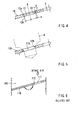
- FIG. 1 is a front view of a first representative intake air control device for an internal combustion engine;
- FIG. 2 is a cross-sectional view of a portion of the first representative intake air control device;
- FIG. 3 is a plan view of a valve member of the first representative intake air control device;
- FIG. 4 is a partial, cross-sectional view of the valve member having an orifice;
- FIG. 5 is a view similar to FIG. 4, but instead showing a partial, cross-sectional view of a valve member having an orifice of a second representative intake air control device; and
- FIG. 6 is a cross-sectional view of a portion of a known intake air control device.
- In one embodiment of the present teachings, intake air control devices may include at least one valve member. The valve member is rotatably disposed within a corresponding air intake port that is formed in a valve body. The valve body is preferably arranged and constructed to be mounted on an internal combustion engine. The valve member may be operable to open and close the air intake port. At least one orifice may be defined within the valve member. The orifice preferably includes a circumferential wall having at least one wall portion that defines an open area (opening). The cross-section (size) of the open area (opening) preferably decreases in the direction from an upstream side to a downstream side of the valve member. In this case, as the intake air flows through the orifice, the flow rate of the intake air will increase. As a result, stagnation in the intake air that flows through the orifice may be minimized to consequently minimize the deposition of combustion products or impurities on the circumferential wall of the orifice.
- In another embodiment of the present teachings, the wall portion may define a linear inclined or beveled surface as viewed in a cross-sectional view along an axis of the orifice.
- In another embodiment of the present teachings, the wall portion may define a convexly curved surface as viewed in a cross-sectional view along an axis of the orifice.
- Each of the additional features and teachings disclosed above and below may be utilized separately or in conjunction with other features and teachings to provide improved intake air control devices and methods for designing and using such control devices. Representative examples of the present invention, which examples utilize many of these additional features and teachings both separately and in conjunction, will now be described in detail with reference to the attached drawings. This detailed description is merely intended to teach a person of skill in the art further details for practicing preferred aspects of the present teachings and is not intended to limit the scope of the invention. Only the claims define the scope of the claimed invention. Therefore, combinations of features and steps disclosed in the following detail description may not be necessary to practice the invention in the broadest sense, and are instead taught merely to particularly describe representative examples of the invention. Moreover, various features of the representative examples and the dependent claims may be combined in ways that are not specifically enumerated in order to provide additional useful embodiments of the present teachings.
- A first representative intake
air control device 20 will now be described with reference to FIGS. 1 to 4. The basic construction of the first representative intakeair control device 20 may be the same or substantially the same as known devices, such as the intake air control device taught by Japanese Laid-Open Publication No. 5-133234. Therefore, the basic construction will be described in brief. - A front view of the first representative intake
air control device 20 is shown in FIG. 1. The intakeair control device 20 preferably includes a valve body 1 that is arranged and constructed to be disposed between a cylinder head of an internal combustion engine (not shown) and an intake manifold (not shown). Four pairs of intake ports 3 and 4 may communicate with corresponding cylinders (not shown) of the engine and may serve as intake air channels. Right andleft valve shafts 5 may extend through the valve body 1 and may be supported by the valve body 1 such that thevalve shafts 5 can rotate about the same axis. - The intake ports 3 may serve as high-speed side intake ports. A
valve member 10 may be disposed within each intake port 3 and may have a substantially circular disk-shaped configuration. Thevalve member 10 may be attached to thecorresponding valve shaft 5 by means ofscrews 6. Anactuator 8 that is disposed centrally with respect to the valve body 1 may reciprocally rotatably drive thevalve shafts 5. Therefore, thevalve member 10 is operable to open and close the corresponding intake port 3. - The intake ports 4 may serve as low-speed side intake ports. No valve member is disposed within the intake port 4.
- Referring to FIGS. 2 and 3, a substantially
circular orifice 11 may be defined within eachvalve member 10. For example, theorifice 11 may be defined substantially in the center of the upstream-side side portion of thevalve member 10 with respect to thecorresponding valve shaft 5. The upstream-side side portion may be an upper and left side half portion of thevalve member 10 as viewed in FIG. 3. - A representative configuration of the
orifice 11 will be described in more detail with reference to FIG. 4. For example, theorifice 11 may define a central axis A that extends substantially perpendicular to the top and bottom surfaces of thevalve member 10. Acircumferential wall 12 of theorifice 11 may include a straightinclined wall surface 12a defined on an upstream side of theorifice 11. In this case, the cross-sectional area (size) of theorifice 11 at the portion of theorifice 11 that is defined by theinclined wall surface 12a will decrease in the direction toward the downstream side. The straightinclined wall surface 12a may also be referred to as abeveled surface 12a or achamfered surface 12a. Thus, thecircumferential wall 12 preferably tapers toward the downstream side along theinclined wall surface 12a. Theinclined wall surface 12a may extend over the entire circumferential length of thecircumferential wall 12 in a manner like a chamfered edge. Thus, the cross-sectional area (size) of theorifice 11 may gradually decrease toward the downstream side along theinclined wall surface 12a. - The portion of the
circumferential wall 12 of theorifice 11 that is downstream of theinclined wall surface 12a may be defined as a straightcylindrical wall surface 12b that is connected to the downstream side edge or a minimum diameter edge of theinclined wall surface 12a. In one representative embodiment, theorifice 11 may be formed within thevalve member 10 by (1) countersinking theinclined wall portion 12a and then (2) drilling thecylindrical wall 12b. - In the representative embodiment shown in FIG. 3, the outer diameter D of the
valve member 10 may be 25.5 mm. The thickness t of thevalve member 10, as indicated in FIG. 4, may be 1.0 mm. The diameter d of theorifice 11 may be 4.8 mm. The dimension of theinclined wall portion 12a may be C0.4. Herein, C0.4 indicates that theinclined wall portion 12a is inclined or chamfered by an angle of θ = 45° and each of the length a in the diametrical direction and b in the axial direction of theorifice 11 is 0.4 mm. - According to the first representative intake
air control device 20, when thevalve member 10 is fully closed, the intake air flows through the corresponding intake port 3 via theorifice 11 formed in thevalve member 10. Because thecircumferential wall 12 of theorifice 11 includes theinclined wall surface 12a, which extends linearly in cross section, the cross-sectional area (size) of theorifice 11 decreases toward the downstream side from the upstream side. - Therefore, the
inclined wall surface 12a may serve to increase the flow rate of the intake air that flows through theorifice 11. The present inventors have performed several comparative experiments to access the effect of theinclined wall surface 12a. The experimental results indicated that the flow rate of intake air that. flows throughorifice 11 having thecircumferential wall 12 with theinclined wall surface 12a is 5 m/s. In comparison, under the same conditions, the flow rate of intake air that flows throughorifice 111 having the straightcircumferential wall 112 of the known device shown in FIG. 6 is only 1 m/s. Thus, it has been confirmed that thecircumferential wall 12 with theinclined wall surface 12a effectively increases the flow rate of the intake air. - Because the flow rate of the intake air that flows through the
orifice 11 can be increased by utilizing theinclined wall surface 12a of thecircumferential wall 12, stagnation in the intake air that flows through theorifice 11 may be minimized. Therefore, deposition of combustion products or impurities on thecircumferential wall 12 may be minimized. Because the deposition of combustion products or impurities is minimized, the flow rate of the intake air will not decrease during operation (i.e., due to deposited combustion products or impurities) and the required air flow rate(s) can be ensured even during extended operation. - In the above first representative embodiment, the
inclined wall surface 12a is partially formed on the upstream side of thecircumferential wall 12. However, theinclined wall surface 12a may be partially formed on the downstream side of thecircumferential wall 12 or may be partially formed on an intermediate portion of thecircumferential wall 12 in the axial direction. In the alternative, theinclined wall surface 12a may extend across the entire thickness of thevalve member 10, i.e. along the entire length of thecircumferential wall 12 in the axial direction. - A second representative intake air control device will now be described with reference to FIG. 5. The second representative intake air control device is different from the first representative intake air control device only in the configuration of the orifice defined within the valve member. Therefore, in FIG. 5, only a part of
valve member 10A is shown and explanation of the other members will not be necessary. - An
orifice 11A may extend through thevalve member 10A and may define a central axis that is the same as the central axis A of the firstrepresentative orifice 11. Theorifice 11A may include acircumferential wall 12A that is formed as a convexly curved surface in cross section along the central axis. In this case, the cross-sectional area (size) defined by thecircumferential wall 12A gradually decreases in the direction from the upstream side to the downstream side. Thus, the cross-sectional area of theorifice 11A may gradually decrease toward the downstream side. - In one representative embodiment, the
circumferential wall 12A may be formed by using a drill that has adrill bit 8 with a curved outer surface configured to conform to the configuration of theorifice 11A. In the alternative, thecircumferential wall 12A may be formed by punching using a die of a press machine, which die also may have a curved outer surface configured to conform to the configuration of theorifice 11A. In another representative embodiment, the radius r of curvature of thecircumferential wall 12A may be 3 mm. - The same effects as the first representative embodiment also may be attained by the second representative embodiment. Although the
circumferential wall 12A is convexly curved in cross section along the thickness (direction) t of thevalve member 10A in the second representative embodiment, thecircumferential wall 12A may be partly convexly curved in cross section on any of the upstream side, the intermediate portion or the downstream side of thecircumferential wall 12A. In such case, the remaining portion of the circumferential wall may include a straight cylindrical wall surface(s). - The present inventors have performed several simulations in order to analyze stagnation in the intake air with respect to the first and second representative embodiments, as well as the known device. The analysis results indicated that stagnation is significantly decreased in the first and second representative embodiments as compared to the known device.
- The simulations also were performed to compare the improvements to the stagnation problem in the intake air with respect to the following valve members:
- (1) the
valve member 10 of the first representative embodiment, - (2) the
valve member 10A of the second representative embodiment, - (3) an alternative embodiment of the
valve member 10 of the first representative embodiment in which theinclined wall surface 12a is formed to extend through the thickness of thevalve member 10, and - (4) an alternative embodiment of the
valve member 10A of the second representative embodiment in which thecircumferential wall 12A is partially convexly curved on the upstream side. - As a result, stagnation of the intake air decreased in the order of the valve members (4), (1), (3) and (2).
- The present invention is not limited to the above representative embodiments and the above representative embodiment may be modified in various ways. For example, the orifice 11 (11A) of the valve member 10(10A) may have different configurations, such as elliptical configurations, polygonal configurations and/or elongated configurations, in addition to circular configurations. Further, a plurality of orifices 11(11A) may be formed in the valve member 10(10A). Furthermore, the cross-sectional area of the orifice 11(11A) may gradually decrease toward the downstream side with various cross-sectional configurations other than straight inclined configurations and convexly curved configurations.
It is explicitly stated that all features disclosed in the description and/or the claims are intended to be disclosed separately and independently from each other for the purpose of original disclosure as well as for the purpose of restricting the claimed invention independent of the compositions of the features in the embodiments and/or the claims. It is explicitly stated that all value ranges or indications of groups of entities disclose every possible intermediate value or intermediate entity for the purpose of original disclosure as well as for the purpose of restricting the claimed invention.
Claims (5)
- An intake air control device (20) for an internal combustion engine comprising a valve member (10, 10A) disposed within an intake air channel (3) of the internal combustion engine, wherein the valve member is operable to open and close the intake air channel and at least one orifice (11, 11A) is defined within the valve member, characterized in that:the orifice has a circumferential wall (12, 12A) that includes at least one wall portion that defines an open area decreasing in size along the direction from the upstream side to the downstream side of the valve member.
- An intake air control device as in claim 1, wherein the wall portion (12a) defines a beveled surface as viewed in a cross-sectional view along a central axis of the orifice (11).
- An intake air control device as in claim 2, wherein the beveled surface extends along the entire thickness of the valve member (10) along the central axis of the orifice (11).
- An intake air control device as in claim 1, wherein the wall portion defines a convexly curved surface (12A) as viewed in a cross-sectional view along a central axis of the orifice (11A).
- An intake air control device as in claim 4, wherein the convexly curved surface (12A) extends along the entire thickness of the valve member (10A) along the central axis of the orifice (11A).
Applications Claiming Priority (2)
| Application Number | Priority Date | Filing Date | Title |
|---|---|---|---|
| JP2001223356 | 2001-07-24 | ||
| JP2001223356A JP2003035149A (en) | 2001-07-24 | 2001-07-24 | Intake control apparatus for internal combustion engine |
Publications (3)
| Publication Number | Publication Date |
|---|---|
| EP1279812A2 true EP1279812A2 (en) | 2003-01-29 |
| EP1279812A3 EP1279812A3 (en) | 2004-03-31 |
| EP1279812B1 EP1279812B1 (en) | 2008-08-20 |
Family
ID=19056707
Family Applications (1)
| Application Number | Title | Priority Date | Filing Date |
|---|---|---|---|
| EP02016321A Expired - Lifetime EP1279812B1 (en) | 2001-07-24 | 2002-07-24 | Intake air control devices for internal combustion engines |
Country Status (3)
| Country | Link |
|---|---|
| EP (1) | EP1279812B1 (en) |
| JP (1) | JP2003035149A (en) |
| DE (1) | DE60228370D1 (en) |
Cited By (2)
| Publication number | Priority date | Publication date | Assignee | Title |
|---|---|---|---|---|
| FR2879248A1 (en) * | 2004-12-13 | 2006-06-16 | Renault Sas | DEVICE FOR FILLING THE INTAKE DUCTS OF AN INTERNAL COMBUSTION ENGINE |
| WO2008052296A1 (en) * | 2006-10-30 | 2008-05-08 | Nilton Joaquim Santos | Improved air reducer for use in natural gas vehicles |
Families Citing this family (1)
| Publication number | Priority date | Publication date | Assignee | Title |
|---|---|---|---|---|
| CN103742318A (en) * | 2013-12-23 | 2014-04-23 | 广西科技大学 | Engine air inlet manifold |
Citations (2)
| Publication number | Priority date | Publication date | Assignee | Title |
|---|---|---|---|---|
| JPH01118128A (en) | 1987-10-30 | 1989-05-10 | Nippon Denso Co Ltd | Production of chromate type photosensitive material sensitized with basic color matter |
| JPH05133234A (en) | 1991-11-11 | 1993-05-28 | Aisan Ind Co Ltd | Air intake control valve device of internal combustion engine |
Family Cites Families (2)
| Publication number | Priority date | Publication date | Assignee | Title |
|---|---|---|---|---|
| US2080440A (en) * | 1935-10-04 | 1937-05-18 | Harry T Scott | Carburetor |
| JPS52137535A (en) * | 1976-05-14 | 1977-11-17 | Fuji Heavy Ind Ltd | Carburetor |
-
2001
- 2001-07-24 JP JP2001223356A patent/JP2003035149A/en active Pending
-
2002
- 2002-07-24 EP EP02016321A patent/EP1279812B1/en not_active Expired - Lifetime
- 2002-07-24 DE DE60228370T patent/DE60228370D1/en not_active Expired - Fee Related
Patent Citations (2)
| Publication number | Priority date | Publication date | Assignee | Title |
|---|---|---|---|---|
| JPH01118128A (en) | 1987-10-30 | 1989-05-10 | Nippon Denso Co Ltd | Production of chromate type photosensitive material sensitized with basic color matter |
| JPH05133234A (en) | 1991-11-11 | 1993-05-28 | Aisan Ind Co Ltd | Air intake control valve device of internal combustion engine |
Cited By (2)
| Publication number | Priority date | Publication date | Assignee | Title |
|---|---|---|---|---|
| FR2879248A1 (en) * | 2004-12-13 | 2006-06-16 | Renault Sas | DEVICE FOR FILLING THE INTAKE DUCTS OF AN INTERNAL COMBUSTION ENGINE |
| WO2008052296A1 (en) * | 2006-10-30 | 2008-05-08 | Nilton Joaquim Santos | Improved air reducer for use in natural gas vehicles |
Also Published As
| Publication number | Publication date |
|---|---|
| EP1279812A3 (en) | 2004-03-31 |
| JP2003035149A (en) | 2003-02-07 |
| EP1279812B1 (en) | 2008-08-20 |
| DE60228370D1 (en) | 2008-10-02 |
Similar Documents
| Publication | Publication Date | Title |
|---|---|---|
| EP1464805B1 (en) | Intake apparatus for internal combustion engine | |
| US4762102A (en) | Intake device of an internal combustion engine | |
| EP1464806A2 (en) | Intake apparatus for internal combustion engine | |
| EP3366906A1 (en) | Internal combustion engine | |
| JP6992671B2 (en) | Water jacket structure | |
| EP1279812A2 (en) | Intake air control devices for internal combustion engines | |
| US20210140390A1 (en) | Engine | |
| US5138988A (en) | Intake duct | |
| US8459217B2 (en) | Scavenging cover and two-cycle engine | |
| CN101220782A (en) | Method for processing gas port of engine cylinder cover | |
| US8869771B2 (en) | Combustion chamber construction for engine | |
| CN106499541B (en) | internal combustion engine | |
| EP3502449B1 (en) | Intake structure of internal combustion engine | |
| US20100037840A1 (en) | Internal combustion engine | |
| US20020117143A1 (en) | Engine cylinder head assembly | |
| JP4702330B2 (en) | Intake device for internal combustion engine | |
| US4478182A (en) | Helically-shaped intake port of an internal combustion engine | |
| JP5867322B2 (en) | Airflow control device | |
| US20100065004A1 (en) | Mixture Motion Enhancing Intake Manifold Gasket | |
| JP6757100B2 (en) | Engine intake port structure | |
| SE516256C2 (en) | Engine body and cylinder for crankcase coil internal combustion engine | |
| JP3835423B2 (en) | Intake device for internal combustion engine | |
| JP7104564B2 (en) | Cylinder head processing method | |
| JPH05187308A (en) | V-type engine cylinder block | |
| US20090218534A1 (en) | Carburettors |
Legal Events
| Date | Code | Title | Description |
|---|---|---|---|
| PUAI | Public reference made under article 153(3) epc to a published international application that has entered the european phase |
Free format text: ORIGINAL CODE: 0009012 |
|
| 17P | Request for examination filed |
Effective date: 20020724 |
|
| AK | Designated contracting states |
Designated state(s): AT BE BG CH CY CZ DE DK EE ES FI FR GB GR IE IT LI LU MC NL PT SE SK TR |
|
| AX | Request for extension of the european patent |
Extension state: AL LT LV MK RO SI |
|
| PUAL | Search report despatched |
Free format text: ORIGINAL CODE: 0009013 |
|
| AK | Designated contracting states |
Kind code of ref document: A3 Designated state(s): AT BE BG CH CY CZ DE DK EE ES FI FR GB GR IE IT LI LU MC NL PT SE SK TR |
|
| AX | Request for extension of the european patent |
Extension state: AL LT LV MK RO SI |
|
| 17Q | First examination report despatched |
Effective date: 20041108 |
|
| AKX | Designation fees paid |
Designated state(s): DE FR |
|
| GRAP | Despatch of communication of intention to grant a patent |
Free format text: ORIGINAL CODE: EPIDOSNIGR1 |
|
| GRAS | Grant fee paid |
Free format text: ORIGINAL CODE: EPIDOSNIGR3 |
|
| GRAA | (expected) grant |
Free format text: ORIGINAL CODE: 0009210 |
|
| AK | Designated contracting states |
Kind code of ref document: B1 Designated state(s): DE FR |
|
| REF | Corresponds to: |
Ref document number: 60228370 Country of ref document: DE Date of ref document: 20081002 Kind code of ref document: P |
|
| PLBE | No opposition filed within time limit |
Free format text: ORIGINAL CODE: 0009261 |
|
| STAA | Information on the status of an ep patent application or granted ep patent |
Free format text: STATUS: NO OPPOSITION FILED WITHIN TIME LIMIT |
|
| 26N | No opposition filed |
Effective date: 20090525 |
|
| REG | Reference to a national code |
Ref country code: FR Ref legal event code: ST Effective date: 20100331 |
|
| PG25 | Lapsed in a contracting state [announced via postgrant information from national office to epo] |
Ref country code: FR Free format text: LAPSE BECAUSE OF NON-PAYMENT OF DUE FEES Effective date: 20090731 |
|
| PG25 | Lapsed in a contracting state [announced via postgrant information from national office to epo] |
Ref country code: DE Free format text: LAPSE BECAUSE OF NON-PAYMENT OF DUE FEES Effective date: 20100202 |