EP1279557A2 - Remote control mirror apparatus for automobile - Google Patents
Remote control mirror apparatus for automobile Download PDFInfo
- Publication number
- EP1279557A2 EP1279557A2 EP02016216A EP02016216A EP1279557A2 EP 1279557 A2 EP1279557 A2 EP 1279557A2 EP 02016216 A EP02016216 A EP 02016216A EP 02016216 A EP02016216 A EP 02016216A EP 1279557 A2 EP1279557 A2 EP 1279557A2
- Authority
- EP
- European Patent Office
- Prior art keywords
- moving rod
- down direction
- left direction
- cylindrical portion
- moving
- Prior art date
- Legal status (The legal status is an assumption and is not a legal conclusion. Google has not performed a legal analysis and makes no representation as to the accuracy of the status listed.)
- Granted
Links
- 230000005540 biological transmission Effects 0.000 claims description 28
- 238000012856 packing Methods 0.000 description 5
- 238000010276 construction Methods 0.000 description 1
- 230000000694 effects Effects 0.000 description 1
- 238000012986 modification Methods 0.000 description 1
- 230000004048 modification Effects 0.000 description 1
- 239000011347 resin Substances 0.000 description 1
- 229920005989 resin Polymers 0.000 description 1
Images


Classifications
-
- B—PERFORMING OPERATIONS; TRANSPORTING
- B60—VEHICLES IN GENERAL
- B60R—VEHICLES, VEHICLE FITTINGS, OR VEHICLE PARTS, NOT OTHERWISE PROVIDED FOR
- B60R1/00—Optical viewing arrangements; Real-time viewing arrangements for drivers or passengers using optical image capturing systems, e.g. cameras or video systems specially adapted for use in or on vehicles
- B60R1/02—Rear-view mirror arrangements
- B60R1/06—Rear-view mirror arrangements mounted on vehicle exterior
- B60R1/062—Rear-view mirror arrangements mounted on vehicle exterior with remote control for adjusting position
- B60R1/07—Rear-view mirror arrangements mounted on vehicle exterior with remote control for adjusting position by electrically powered actuators
- B60R1/072—Rear-view mirror arrangements mounted on vehicle exterior with remote control for adjusting position by electrically powered actuators for adjusting the mirror relative to its housing
Definitions
- the present invention relates to a remote control mirror for automobiles, such as a door mirror, a fender mirror, and a rearview mirror.
- a remote control mirror for automobiles, such as a door mirror, a fender mirror, and a rearview mirror.
- the "right and left” or the “right and left direction” refers to the “right and left” or the “right and left direction” around the vertical axis with the remote control mirror mounted on an automobile.
- the "up and down” or the “up and down direction” refers to the “right and left” or the “right and left direction” around the horizontal axis with the remote control mirror mounted on the automobile.
- a remote control mirror generally comprises a power unit and a mirror unit mounted on the power unit tiltably.
- the power unit comprises a housing, a motor housed in the housing, a moving rod mounted on the housing movably and interlocked with the mirror unit, a deceleration mechanism and a moving mechanism provided between the motor and the moving rod.
- the moving rod is moved via the deceleration mechanism and the moving mechanism so as to tilt the mirror unit.
- the load on the motor or the deceleration mechanism can be alleviated at the time the moving rod is disposed at the most receded position, and that slip off of the moving rod from the other members can be prevented at the time the moving rod is disposed at the most advanced position.
- the remote control mirror comprises a stopper to be contacted with the moving rod before it is located at the most receded position such that the elastic engagement between a female screw and an elastic engaging nail is in the state capable of clutch slipping, between the housing and the moving rod.
- the remote control mirror comprises a fall-off preventing unit to be contacted with the moving rod at the time the moving rod is located at the most advanced position for preventing fall-off of the moving rod from the other member between the moving rod and another member.
- the remote control mirror in this embodiment is an example used for a door mirror apparatus.
- the present invention is not limited by this embodiment.
- the remote control mirror shown in Figs. 1 and 2 is a so-called door mirror apparatus 1.
- the door mirror apparatus 1 comprises a base 3 fixed on a door 2 of an automobile and a mirror assembly 4 mounted tiltably around the substantially vertical axis of the base 3.
- a fender mirror apparatus, a rearview mirror apparatus, or the like can be included.
- the mirror unit 10 comprises a mirror body 11, a mirror holder 12 which supports the mirror body 11, and a mirror holder base 13 mounted on the center part of the mirror holder 12.
- the power unit 9 comprises a first housing 17, a second housing 18 (hereinafter referred to as the housings 17, 18), and other components described later.
- the first housing 17 is provided with the pivot mechanism 15 and the guide mechanism 16, respectively.
- the mirror holder base 13 is mounted on the first housing 17 of the power unit 9 via a spring 19, the pivot mechanism 15 and the guide mechanism 16 tiltably in the right and left direction and the up and down direction.
- the spring 19 may be one with a cross-like shape formed integrally, or one comprising two pieces with a minus shape in a combination so as to form a cross-like shape.
- a motor 22A for the right and left direction and a motor 22B for the up and down direction (hereinafter referred to as the motors 22A, 22B) are stored in the housings 17, 18, respectively.
- a moving rod 23A for the right and left direction, and a moving rod 23B for the up and down direction (hereinafter referred to as the moving rods 23A, 23B) are mounted movably in the housings 17, 18, respectively.
- the moving rods 23A, 23B are inserted through the openings 20A, 208.
- the packings 21A, 21B are disposed water-tightly between the outer side surface of the moving rods 23A, 23B and the rim of the openings 20A, 20B.
- a deceleration mechanism for the right and left direction, a deceleration mechanism for the up and down direction (hereinafter referred to as the deceleration mechanism), a moving mechanism for the right and left direction and a moving mechanism for the up and down direction (hereinafter referred to as the moving mechanism) are provided between the moving rods 23A, 23B and the motors 22A, 22B, respectively.
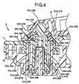
- the moving rods 23A, 23B are made of a resin with elasticity. As shown in Figs. 4 and 5, the moving rods 23A, 23B have a cylindrical shape with hollowness from one end to halfway at the other end. On one end of the moving rods 23A, 23B, four elastic engaging nails 28A for the right and left direction and elastic engaging nails 28B for the up and down direction (hereinafter referred to as the elastic engaging nails 28A, 28B) are provided toward the outer side by a substantially equal interval, respectively.
- a spherical portion 30A for the right and left direction and a spherical portion 30B for the.up and down direction are provided integrally.
- the helical gears 25A, 25B comprise a hollow double cylindrical shape, that is, an outer side cylindrical portion 40A for the right and left direction, an outer side cylindrical portion 40B for the up and down direction (hereinafter referred to as the outer side cylindrical portions 40A, 40B), an inner side cylindrical portion 41A for the right and left direction, and an inner side cylindrical portion 41B for the up and down direction (hereinafter referred to as the inner side cylindrical portions 41A, 41B).
- the axial direction lengths of the outer side cylindrical portions 40A, 40B is shorter than the axial direction lengths of the inner side cylindrical portions 41A, 41B.
- portions 41A, 41B is interlocked integrally via an interlocking portion 39A for the right and left direction and an interlocking portion 39B for the up and down direction (hereinafter referred to as the interlocking portions 39A, 39B), respectively.
- the outer side surface of the outer side cylindrical portions 40A, 40B is provided with a gear 33A for the right and left direction of the helical gear and a gear 33B for the up and down direction, respectively.
- transmission holes 26A, 26B are provided from one end to the other end of the inner side cylindrical portions 41A, 41B each in the axial direction (moving direction of the moving rods 23A, 23B).
- the four transmission holes 26A, 26B and the four elastic engaging nails 28A, 28B correspond with each other.
- the moving mechanism comprises a female screw 27A for the right and left direction provided in the second housing 18, a female screw 27B for the up and down direction (hereinafter referred to as the female screws 27A, 27B), the elastic engaging nails 28A, 28B of the moving rods 23A, 23B, a spring 29A for the right and left direction and a spring 298 for the up and down direction (hereinafter referred to as the springs 29A, 29B).
- the springs 29A, 29B As shown in Figs.
- the female screws 27A, 27B are provided each on the inner side surface of a hollow cylindrical portion 34A for the right and left direction and a hollow cylindrical portion 34B for the up and down direction (hereinafter referred to as the hollow cylindrical portions 34A, 34B) provided integrally with the second housing 18.
- the outer diameter of the moving rods 23A, 23B and the inner diameter of the inner side cylindrical portions 41A, 41B are substantially equal.
- the moving rods 23A, 23B are supported in the inner side cylindrical portions 41A, 41B of the helical gears 25A, 25B movably in the moving direction of the moving rods 23A, 23B.
- the springs 29A, 29B are disposed in the moving rods 23A, 23B.
- the elastic engaging nails 28A, 28B are always elastically engaged with the female screws 27A, 27B through the transmission holes 26A, 26B, respectively.
- the moving rods 23A, 23B and the helical gears 25A, 25B are rotated synchronously.
- the elastic engaging nails 28A, 28B are always elastically engaged with the female screws 27A, 27B according to the elastic function of the elastic engaging nails 28A, 28B themselves, the springs 29A, 29B need not always be provided.
- the elastic engaging nails 28A, 28B are movable in the moving direction of the moving rods 23A, 23B (axial direction of the helical gears 25A, 25B) in the transmission holes 26A, 26B.
- the moving rods 23A, 23B are maintained water-tightly by the packings 21A, 21B. Moreover, the spherical portions 30A, 30B of the moving rods 23A, 23B and the spherical recess portions 14A, 14B of the mirror holder base 16 are fitted with each other. Thereby, the mirror holder base 13 can be tilted in the right and left direction and the up and down direction.
- a stopper is provided between the second housing 18 and the moving rods 23A, 23B.
- the stopper comprises pins 35A, 35B provided concentrically and integrally with the hollow cylindrical portions 34A, 34B in the second housing 18, and projection portions 36A, 36B integrally in the hollow parts of the moving rods 23A, 23B from the other end to the halfway.
- a fall-off preventing unit is provided between the moving rods 23A, 23B and another member, in this embodiment, the helical gears 25A, 25B.
- the fall-off preventing unit comprises step portions 37A, 37B provided on the upper surface of the elastic engaging nails 28A, 2BB, and protruding portions 38A, 38B provided on one end of the through holes 26A, 26B of the helical gears 25A, 25B.
- the protruding portions 38A, 38B may be provided on the first housing 17 side as well.
- the fall-off preventing unit comprising the step portions 37A, 37B and the protruding portions 38A, 38B are for preventing fall-off of the moving rods 23A, 23B from the helical gears 25A, 25B (housings 17, 18) by contacting with the moving rods 23A, 23B at the time they are located at the most advanced position.
- the power unit 9 and a harness 31 on the power source side can be connected electrically so that the motors 22A, 22B can be in the state capable of being energized.
- the motor 22A for the right and left direction is energized by the remote control from the driver's seat of the automobile. Then, the motor 22A for the right and left direction is driven so that the moving rod 23A for the right and left direction is moved. According thereto, the mirror unit 10 is tilted with respect to the power unit 9 via the mirror holder base 13 in the right and left direction around the vertical axis (not shown) through the center of the pivot mechanism 15. Or when the motor 22B for the up and down direction is energized, the motor 22B for the up and down direction is driven so that the moving rod 23B for the up and down direction is moved. According thereto, the mirror unit 10 is tilted with respect to the power unit 9 via the mirror holder base 13 in the up and down direction around the horizontal axis (not shown) through the center of the pivot mechanism 15.
- the moving rods 23A, 23B are receded so as to be located at a position before the most receded position.
- the pins 35A, 35B of the stopper and the projection portions 36A, 36B are contacted via the springs 29A, 29B.
- the elastic engagement of the female screws 27A, 27B and the elastic engaging nails 28A, 28B can be in the state capable of clutch slipping.
- the moving rods 23A, 23B are to be further receded.
- the driving force of the motors 22A, 22B is transmitted to the helical gears 25A, 25B via the worms 24A, 24B.
- the helical gears 25A, 25B and the moving rods 23A, 23B are to be rotated synchronously.
- the elastic engaging nails 28A, 28B are to be screw swirled along the female screws 27A, 27B.
- the elastic engaging nails 28A, 28B are deflected in the arrow direction in Fig. 4, resisting to their own elastic function and the spring function of the springs 29A, 29B so as to move over the screw threads of the female screws 27A, 27B. According thereto, the elastic engagement of the female screws 27A, 27B and the elastic engaging nails 28A, 28B is released. Then, the elastic engaging nails 28A, 28B restore automatically in the direction opposite to the arrow in Fig. 4 by their own elastic function and the spring function of the springs 29A, 29B so as to be engaged with the female screws 27A, 27B again.
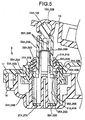
- Fig. 5 shows the state with the moving rods 23A, 23B disposed at a position before the most advanced position, that is, the state just before contacting the step portions 37A, 37B of the fall-off preventing member and the protruding portions 38A, 38B. From the state shown in Fig. 5, the moving rods 23A, 23B are further advanced so as to be located at the most advanced position. Then, the step portions 37A, 37B of the fall-off preventing member and the protruding portions 38A, 38B are contacted. As a result, fall-off of the moving rods 23A, 23B from the helical gears 25A, 25B (or the housings 17, 18 as another member) can be prevented.
- the outer side cylindrical portions 40A, 40B and the outer diameter of the hollow cylindrical portions 34A, 34B are substantially equal, the outer side cylindrical portions 40A, 40B of the helical gears 25A, 25B can be supported certainly rotatably around the hollow cylindrical portions 34A, 34B without backlash.
- the outer diameter of the moving rods 23A, 23B and the inner diameter of the inner side cylindrical portions 41A, 41B are substantially equal, the moving rods 23A, 23B can be supported certainly movably in the inner side cylindrical portions 41A, 41B of the helical gears 25A, 25B without backlash.
- the stopper comprises the pins 35A, 35B provided in the second housing 18 and the projection portions 36A, 36B provided in the moving rods 23A, 238.
- a stopper other than the pins 35A, 35B, and projection portions 36A, 36B can be used as well, as long as it is provided between the housings 17, 18 and the moving rods 23A, 23B.
Landscapes
- Engineering & Computer Science (AREA)
- Multimedia (AREA)
- Mechanical Engineering (AREA)
- Rear-View Mirror Devices That Are Mounted On The Exterior Of The Vehicle (AREA)
Abstract
Description
- The present invention relates to a remote control mirror for automobiles, such as a door mirror, a fender mirror, and a rearview mirror. In the claims and the specification, the "right and left" or the "right and left direction" refers to the "right and left" or the "right and left direction" around the vertical axis with the remote control mirror mounted on an automobile. Moreover, the "up and down" or the "up and down direction" refers to the "right and left" or the "right and left direction" around the horizontal axis with the remote control mirror mounted on the automobile.
- Conventional remote control mirror for automobiles have been disclosed in the U. S. Patent No. 4,696,555, U. S. Patent No. 4,940,321 and the Japanese Patent Application Laid-Open (JP-A) No. 2000-118304.
- A remote control mirror generally comprises a power unit and a mirror unit mounted on the power unit tiltably. The power unit comprises a housing, a motor housed in the housing, a moving rod mounted on the housing movably and interlocked with the mirror unit, a deceleration mechanism and a moving mechanism provided between the motor and the moving rod. When the motor is driven by the remote control, the moving rod is moved via the deceleration mechanism and the moving mechanism so as to tilt the mirror unit.
- In the remote control mirror, it is important that the load on the motor or the deceleration mechanism can be alleviated at the time the moving rod is disposed at the most receded position, and that slip off of the moving rod from the other members can be prevented at the time the moving rod is disposed at the most advanced position.
- It is an object of the present invention to provide a remote control mirror, which can alleviate the load on a motor or a deceleration mechanism at the time a moving rod is disposed at the most receded position, and can prevent slip off of the moving rod from the other members at the time the moving rod is disposed at the most advanced position.
- The remote control mirror according to one aspect of the invention comprises a stopper to be contacted with the moving rod before it is located at the most receded position such that the elastic engagement between a female screw and an elastic engaging nail is in the state capable of clutch slipping, between the housing and the moving rod. As a result, according to the above aspect, since the elastic engagement between the female screw and the elastic engaging nail can be clutch slipped before the moving rod is located at the most receded position, the load on the motor or the deceleration mechanism can be alleviated at the time the moving rod is located at the most receded position.
- The remote control mirror according to another aspect of the invention comprises a fall-off preventing unit to be contacted with the moving rod at the time the moving rod is located at the most advanced position for preventing fall-off of the moving rod from the other member between the moving rod and another member. As a result, according to the above aspect, since the fall-off preventing unit is contacted with the moving rod when it is located at the most advanced position, fall-off of the moving rod from the other member can be prevented at the time the moving rod is located at the most advanced position.
- These and other objects, features and advantages of the present invention are specifically set forth in or will become apparent from the following detailed descriptions of the invention when read in conjunction with the accompanying drawings.
-
- Fig. 1 is a perspective view of a door mirror apparatus of an embodiment of a remote control mirror according to the present invention,
- Fig. 2 is a cross-sectional view taken on the line II-II of Fig. 1,
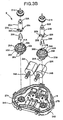
- Fig. 3A is an exploded perspective view of a spring, a holder base, and a first housing of a power unit of the remote control mirror,
- Fig. 3B is an exploded perspective view of the power unit of the remote control mirror,
- Fig. 4 is a cross-sectional view taken on the line IV-IV of Fig. 2 at the time the moving rod is located at the most receded position, and
- Fig. 5 is a cross-sectional view taken on the line IV-IV of Fig. 2 at the time the moving rod is located at the most advanced position.
- Embodiment(s) of the remote control mirror according to the present invention will be explained with reference to the accompanied drawings. The remote control mirror in this embodiment is an example used for a door mirror apparatus. The present invention is not limited by this embodiment.
- The remote control mirror shown in Figs. 1 and 2 is a so-called
door mirror apparatus 1. Thedoor mirror apparatus 1 comprises a base 3 fixed on adoor 2 of an automobile and amirror assembly 4 mounted tiltably around the substantially vertical axis of the base 3. As the remote control mirror, in addition to thedoor mirror apparatus 1, a fender mirror apparatus, a rearview mirror apparatus, or the like can be included. - As shown in Fig. 2, the
mirror assembly 4 comprises amirror housing 5, aunit bracket 7 mounted on themirror housing 5 by a screw 6, or the like, apower unit 9 mounted on theunit bracket 7 by ascrew 8, or the like and amirror unit 10 mounted on thepower unit 9 tiltably. - Similarly, as shown in Fig. 2, the
mirror unit 10 comprises amirror body 11, amirror holder 12 which supports themirror body 11, and amirror holder base 13 mounted on the center part of themirror holder 12. - As shown in Fig. 3A, the
mirror holder base 13 is provided with aspherical recess portion 14A for the right and left direction, arecess portion 14B for the up and down direction (hereinafter referred to as thespherical recess portions pivot mechanism 15 and aguide mechanism 16, respectively. Themirror holder 12 and themirror holder base 13 are provided as individual structures such that an integral structure can be provided by assembling themirror holder base 13 in the center part of themirror holder 12. In the present invention, themirror holder 12 and themirror holder base 13 can be provided as an integral structure. - In contrast, as shown in Figs. 2, 3A and 3B, the
power unit 9 comprises afirst housing 17, a second housing 18 (hereinafter referred to as thehousings 17, 18), and other components described later. - The
first housing 17 is provided with thepivot mechanism 15 and theguide mechanism 16, respectively. Themirror holder base 13 is mounted on thefirst housing 17 of thepower unit 9 via aspring 19, thepivot mechanism 15 and theguide mechanism 16 tiltably in the right and left direction and the up and down direction. Thespring 19 may be one with a cross-like shape formed integrally, or one comprising two pieces with a minus shape in a combination so as to form a cross-like shape. - The
first housing 17 is provided with a round opening 20A for the right and left direction and an opening 20B for the up and down direction (hereinafter referred to as theopenings packing 21B for the up and down direction (hereinafter referred to as thepackings openings - A
motor 22A for the right and left direction and amotor 22B for the up and down direction (hereinafter referred to as themotors housings rod 23A for the right and left direction, and a movingrod 23B for the up and down direction (hereinafter referred to as the movingrods housings rods openings 20A, 208. Thepackings rods openings - A deceleration mechanism for the right and left direction, a deceleration mechanism for the up and down direction (hereinafter referred to as the deceleration mechanism), a moving mechanism for the right and left direction and a moving mechanism for the up and down direction (hereinafter referred to as the moving mechanism) are provided between the moving
rods motors - The moving
rods rods rods engaging nails 28A for the right and left direction and elasticengaging nails 28B for the up and down direction (hereinafter referred to as the elasticengaging nails rods spherical portion 30A for the right and left direction and aspherical portion 30B for the.up and down direction (hereinafter referred to as thespherical portions - As shown in Fig. 3B, the deceleration mechanism comprises a
worm 24A for the right and left direction and a worm 24B for the up and down direction (hereinafter referred to as theworms 24A, 24B) mounted each on the rotation axes of themotors helical gear 25A for the right and left direction and ahelical gear 25B for the up and down direction (hereinafter referred to as thehelical gears worms 24A, 24B. - As shown in Figs. 4 and 5, the
helical gears cylindrical portion 40A for the right and left direction, an outer sidecylindrical portion 40B for the up and down direction (hereinafter referred to as the outer sidecylindrical portions cylindrical portion 41A for the right and left direction, and an inner sidecylindrical portion 41B for the up and down direction (hereinafter referred to as the inner sidecylindrical portions cylindrical portions cylindrical portions - A gap between one end of the outer side
cylindrical portions portions portion 39A for the right and left direction and an interlockingportion 39B for the up and down direction (hereinafter referred to as the interlockingportions cylindrical portions gear 33A for the right and left direction of the helical gear and agear 33B for the up and down direction, respectively. In contrast, four long hole-like transmission holes 26A for the right and left direction andtransmission holes 26B for the up and down direction (hereinafter referred to as thetransmission holes cylindrical portions rods transmission holes engaging nails - As shown in Figs. 3B, 4 and 5, the moving mechanism comprises a
female screw 27A for the right and left direction provided in thesecond housing 18, a female screw 27B for the up and down direction (hereinafter referred to as thefemale screws 27A, 27B), the elastic engagingnails rods spring 29A for the right and left direction and aspring 298 for the up and down direction (hereinafter referred to as thesprings female screws 27A, 27B are provided each on the inner side surface of a hollowcylindrical portion 34A for the right and left direction and a hollowcylindrical portion 34B for the up and down direction (hereinafter referred to as the hollowcylindrical portions second housing 18. - The inner diameter of the outer side
cylindrical portions cylindrical portions cylindrical portions cylindrical portions female screws 27A, 27B. - As shown in Figs. 4 and 5, the outer side
cylindrical portions helical gears cylindrical portions cylindrical portions helical gears cylindrical portions portions helical gears rods cylindrical portions first housing 17. - As a result, the
helical gears housings rods - As shown in Figs. 4 and 5, the outer diameter of the moving
rods cylindrical portions rods cylindrical portions helical gears rods springs rods springs nails female screws 27A, 27B through the transmission holes 26A, 26B, respectively. - According to the contact of the side wall surface of the elastic engaging
nails rods helical gears nails female screws 27A, 27B according to the elastic function of the elastic engagingnails springs nails rods helical gears - As a result, the moving
rods housing motors rods helical gears nails 28A, 283 and thefemale screws 27A, 27B, the movingrods housings helical gears housings - The moving
rods packings spherical portions rods spherical recess portions mirror holder base 16 are fitted with each other. Thereby, themirror holder base 13 can be tilted in the right and left direction and the up and down direction. - A stopper is provided between the
second housing 18 and the movingrods pins cylindrical portions second housing 18, andprojection portions rods - The
pins rods projection portions rods springs rods projection portions - The stopper comprising the
pins projection portions springs rods female screws 27A, 27B and the elastic engagingnails rods cylindrical portions helical gears - A fall-off preventing unit is provided between the moving
rods helical gears step portions nails 28A, 2BB, and protrudingportions holes helical gears portions first housing 17 side as well. - The fall-off preventing unit comprising the
step portions portions rods helical gears housings 17, 18) by contacting with the movingrods - As shown in Fig. 2, by connecting two
male connector 32A for the right and left direction andmale connector 32B for the up and down direction each with thepower unit 9 as a female connector, thepower unit 9 and aharness 31 on the power source side can be connected electrically so that themotors - An operation of the remote control mirror according to this embodiment will be explained hereinafter.
- The
motor 22A for the right and left direction is energized by the remote control from the driver's seat of the automobile. Then, themotor 22A for the right and left direction is driven so that the movingrod 23A for the right and left direction is moved. According thereto, themirror unit 10 is tilted with respect to thepower unit 9 via themirror holder base 13 in the right and left direction around the vertical axis (not shown) through the center of thepivot mechanism 15. Or when themotor 22B for the up and down direction is energized, themotor 22B for the up and down direction is driven so that the movingrod 23B for the up and down direction is moved. According thereto, themirror unit 10 is tilted with respect to thepower unit 9 via themirror holder base 13 in the up and down direction around the horizontal axis (not shown) through the center of thepivot mechanism 15. - The effects obtained by the remote control mirror according to this embodiment are as follows.
- As shown in Fig. 4, the moving
rods pins projection portions springs female screws 27A, 27B and the elastic engagingnails - That is, in the state with the
pins projection portions springs rods motors helical gears worms 24A, 24B. The helical gears 25A, 25B and the movingrods nails female screws 27A, 27B. - Then, the elastic engaging
nails springs female screws 27A, 27B. According thereto, the elastic engagement of thefemale screws 27A, 27B and the elastic engagingnails nails springs female screws 27A, 27B again. - Thereby, the load on the deceleration mechanism (
worms 24A, 24B and thehelical gears motors rods - Fig. 5 shows the state with the moving
rods step portions portions rods step portions portions rods helical gears housings - According to this embodiment, since the inner diameter of the outer side
cylindrical portions cylindrical portions cylindrical portions helical gears cylindrical portions rods cylindrical portions rods cylindrical portions helical gears - In this embodiment, the stopper comprises the
pins second housing 18 and theprojection portions rods 23A, 238. However, according to the present invention, a stopper other than thepins projection portions housings rods - In this embodiment, the fall-off preventing unit comprises the
step portions nails portions helical gears step portions portions rods - Although the invention has been described with respect to a specific embodiment for a complete and clear disclosure, the appended claims are not to be thus limited but are to be construed as embodying all modifications and alternative constructions that may occur to one skilled in the art which fairly fall within the basic teaching herein set forth.
Claims (13)
- A remote control mirror for an automobile comprising:a power unit; and a mirror unit mounted on the power unit, the mirror unit being rotated by the power unit by remote control,the power unit including
a housing;
a motor housed in the housing;
a moving rod mounted movably in the housing and interlocked with the mirror unit; and
a deceleration mechanism and a moving mechanism provided between the motor and the moving rod for moving the moving rod by the drive of the motor and for tilting the mirror unit,
the moving mechanism having a female screw provided in the housing; and an elastic engaging nail provided in the moving rod such that the elastic engaging nail is elastically engaged with the female screw, whereina stopper to be contacted with the moving rod before it is located at the most receded position such that the elastic engagement between the female screw and the elastic engaging nail is in the state capable of clutch slipping, is provided between the housing and the moving rod. - The remote control mirror according to claim 1, wherein the deceleration mechanism comprises a hollow double cylindrical shaped helical gear such that the helical gear is mounted rotatably and unmovably in the moving direction of the moving rod on a hollow cylindrical portion provided in the housing, with the inner diameter of an outer side cylindrical portion of the helical gear and the outer diameter of the hollow cylindrical portion being substantially equal, and the outer diameter of the inner side cylindrical portion of the helical gear being smaller than the inner diameter of the hollow cylindrical portion, the moving rod is supported movably in the inner side cylindrical portion, with the outer diameter of the moving rod and the inner diameter of the inner side cylindrical portion being substantially equal, the female screw is provided on the inner side surface of the hollow cylindrical portion, a long hole-like transmission hole is provided in the inner side cylindrical portion in the moving direction of the moving rod, with the elastic engaging nail being elastically engaged with the female screw through the transmission hole, and the moving rod is moved while being synchronously rotated with the helical gear.
- The remote control mirror according to claim 1, wherein the stopper comprises a pin provided in the housing, and a projection port ion provided in the hollow part of the moving rod with the hollow shape such that the pin is inserted in the hollow part of the moving rod so as to face the projection portion with respect to the moving direction of the moving rod.
- The remote control mirror according to claim 1, wherein the deceleration mechanism comprises a hollow double cylindrical shaped helical gear such that the helical gear is mounted rotatably and unmovably in the moving direction of the moving rod on a hollow cylindrical portion provided in the housing, with the inner diameter of an outer side cylindrical portion of the helical gear and the outer diameter of the hollow cylindrical portion being substantially equal, and the outer diameter of the inner side cylindrical portion of the helical gear being smaller than the inner diameter of the hollow cylindrical portion, the moving rod is supported movably in the inner side cylindrical portion, with the outer diameter of the moving rod and the inner diameter of the inner side cylindrical portion being substantially equal, the female screw is provided on the inner side surface of the hollow cylindrical portion, a long hole-like transmission hole is provided in the inner side cylindrical portion in the moving direction of the moving rod, with the elastic engaging nail being elastically engaged with the female screw through the transmission hole, the moving rod is moved while being synchronously rotated with the helical gear, and the stopper comprises a pin provided concentrically with the hollow cylindrical portion in the housing, and a projection portion provided in the hollow part of the moving rod with the hollow shape such that the pin is inserted in the hollow part of the moving rod so as to face the projections portion.
- A remote control mirror for an automobile comprising:a power unit; and a mirror unit mounted on the power unit, the mirror unit being rotated by the power unit by remote control,the power unit including
a housing;
a motor housed in the housing, a moving rod mounted movably in the housing and interlocked with the mirror unit;
a deceleration mechanism and a moving mechanism provided between the motor and the moving rod for moving the moving rod by the drive of the motor for tilting the mirror unit, whereina fall-off preventing unit to be contacted with the moving rod at the time it is located at the most advanced position for preventing fall-off of the moving rod from the other member is provided between the moving rod and another member. - The remote control mirror according to claim 5, wherein the moving mechanism comprises a female screw provided in the housing, and an elastic engaging nail provided in the moving rod such that the elastic engaging nail is elastically engaged with the female screw, the deceleration mechanism comprises a hollow double cylindrical shaped helical gear such that the helical gear is mounted rotatably and unmovably in the moving direction of the moving rod on a hollow cylindrical portion provided in the housing, with the inner diameter of an outer side cylindrical portion of the helical gear and the outer diameter of the hollow cylindrical portion being substantially equal, and the outer diameter of the inner side cylindrical portion of the helical gear being smaller than the inner diameter of the hollow cylindrical portion, the moving rod is supported movably in the inner side cylindrical portion, with the outer diameter of the moving rod and the inner diameter of the inner side cylindrical portion being substantially equal, the female screw is provided on the inner side surface of the hollow cylindrical portion, a long hole-like transmission hole is provided in the inner side cylindrical portion in the moving direction of the moving rod, with the elastic engaging nail being elastically engaged with the female screw through the transmission hole, and the moving rod is moved while being synchronously rotated with the helical gear.
- The remote control mirror according to claim 5, wherein the fall-off preventing unit comprises a step portion provided in the moving rod and a protruding portion provided in the other member such that the step portion and the protruding portion face with each other with respect to the moving direction of the moving rod.
- The remote control mirror according to claim 6, wherein the moving mechanism comprises a female screw provided in the housing, and an elastic engaging nail provided in the moving rod such that the elastic engaging nail is elastically engaged with the female screw, the deceleration mechanism comprises a hollow double cylindrical shaped helical gear such that the helical gear is mounted rotatably and unmovably in the moving direction of the moving rod on a hollow cylindrical portion provided in the housing, with the inner diameter of an outer side cylindrical portion of the helical gear and the outer diameter of the hollow cylindrical portion being substantially equal, and the outer diameter of the inner side cylindrical portion of the helical gear being smaller than the inner diameter of the hollow cylindrical portion, the moving rod is supported movably in the inner side cylindrical portion, with the outer diameter of the moving rod and the inner diameter of the inner side cylindrical portion being substantially equal, the female screw is provided on the inner side surface of the hollow cylindrical portion, a long hole-like transmission hole is provided in the inner side cylindrical portion in the moving direction of the moving rod, with the elastic engaging nail being elastically engaged with the female screw through the transmission hole, the moving rod is moved while being synchronously rotated with the helical gear, and the fall-off preventing unit comprises a step portion provided in the elastic engaging nail and a protruding portion provided in the transmission hole of the helical gear such that the step portion and the protruding portion face with each other with respect to the moving direction of the moving rod.
- A remote control mirror comprising:a power unit; and a mirror unit mounted on the power unit, the mirror unit being rotated by the power unit by remote control in the right and left direction and the up and down direction,the power unit including
a housing;
a motor for the right and left direction and a motor for the up and down direction housed in the housing;
a moving rod for the right and left direction and a moving rod for the up and down direction mounted movably in the housing and interlocked with the mirror unit;
a deceleration mechanism for the right and left direction, a deceleration mechanism for the up and down direction;
a moving mechanism for the right and left direction and a moving mechanism for the up and down direction provided between the motor for the right and left direction and the motor for the up and down direction, and the moving rod for the right and the left direction and the moving rod for the up and down direction for moving the moving rod for the right and left direction and the moving rod for the up and direction by the drive of the motor for the right and left direction and the motor for the up and down direction for tilting the mirror unit in the right and left direction and the up and down direction,
the moving mechanism for the right and left direction and the moving mechanism for the up and down direction include
a female screw for the right and left direction and a female screw for the up and down direction provided in the housing, and an elastic engaging nail for the right and left direction and an elastic engaging nail for the up and down direction provided in the moving rod for the right and left direction and the moving rod for the up and down direction such that the elastic engaging nail for the right and left direction and the elastic engaging nail for the up and down direction are elastically engaged with the female screw for the right and left direction and. the female screw for the up and down direction,a stopper for the right and left direction and a stopper for the up and down direction to be contacted with the moving rod for the right and left direction and the moving rod for the up and down direction before they are located at the most receded position such that the elastic engagement between the female screw for the right and left direction and the female screw for the up and down direction and the elastic engaging nail for the right and left direction and the elastic engaging nail for the up and down direction is in the state capable of clutch slipping, are provided between the housing and the moving rod for the right and left direction and the moving rod for the up and down direction, anda fall-off preventing unit for the right and left direction and a fall-off preventing unit for the up and down direction to be contacted with the moving rod for the right and left direction and the moving rod for the up and down direction at the time they are located at the most advanced position for preventing fall-off of the moving rod for the right and left direction and the moving rod for the up and down direction from the other member are provided between the moving rod for the right and left direction and the moving rod for the up and down direction and another member. - The remote control mirror according to claim 9, wherein the deceleration mechanism for the right and left direction and the deceleration mechanism for the up and down direction comprise a hollow double cylindrical shaped helical gear for the right and left direction and a helical gear for the up and down direction such that the helical gear for the right and left direction and the helical gear for the up and down direction are mounted rotatably and unmovably in the moving direction of the moving rod on a hollow cylindrical portion for the right and left direction and a hollow cylindrical portion for the up and down direction provided in the housing, with the inner diameter of an outer side cylindrical portion of the helical gear for the right and left direction and the helical gear for the up and down direction and the outer diameter of the hollow cylindrical portion for the right and left direction and the hollow cylindrical portion for the up and down direction being substantially equal, and the outer diameter of the inner side cylindrical portion of the helical gear for the right and left direction and the helical gear for the up and down direction being smaller than the inner diameter of the hollow cylindrical portion for the right and left direction and the hollow cylindrical portion for the up and down direction, the moving rod for the right and left direction and the moving rod for the up and down direction are supported movably in the inner side cylindrical portion for the right and left direction and the inner side cylindrical portion for the up and down direction, with the outer diameter of the moving rod for the right and left direction and the moving rod for the up and down direction and the inner diameter of the inner side cylindrical portion for the right and left direction and the inner side cylindrical portion for the up and down direction being substantially equal, the female screw for the right and left direction and the female screw for the up and down direction are provided on the inner side surface of the hollow cylindrical portion for the right and left direction and the hollow cylindrical portion for the up and down direction, long hole-like transmission hole for the right and left direction and transmission hole for the up and down direction are provided in the inner side cylindrical portion for the right and left direction and the inner side cylindrical portion for the up and down direction in the moving direction of the moving rod for the right and left direction and the moving rod for the up and down direction, with the elastic engaging nail for the right and left direction and the elastic engaging nail for the up and down direction being elastically engaged with the female screw for the right and left direction and the female screw for the up and down direction through the transmission hole for the right and left direction and the transmission hole for the up and down direction, and the moving rod for the right and left direction and the moving rod for the up and down direction are moved while being synchronously rotated with the helical gear for the right and left direction and the helical gear for the up and down direction.
- The remote control mirror according to claim 9, wherein the stopper for the right and left direction and the stopper for the up and down direction comprise a pin for the right and left direction and a pin for the up and down direction provided in the housing, and a projection portion for the right and left direction and a projection portion for the up and down direction provided in the hollow part of the moving rod for the right and left direction and the moving rod for the up and down direction with the hollow shape such that the pin for the right and left direction and the pin for the up and down direction are inserted in the hollow portions of the moving rod for the right and left direction and the moving rod for the up and down direction so as to face the projection portion for the right and left direction and the projection portion for the up and down direction with respect to the moving direction of the moving rod for the right and left direction and the moving rod for the up and down direction.
- The remote control mirror according to claim 9, wherein the fall-off preventing unit for the right and left direction and the fall-off preventing unit for the up and down direction comprise a step portion for the right and left direction and a step portion for the up and down direction provided in the elastic engaging nail for the right and left direction and the elastic engaging nail for the up and down direction and a protruding portion for the right and left direction and a protruding portion for the up and down direction provided in the transmission hole for the right and left direction and the transmission hole for the up and down direction such that the step portion for the right and left direction and the step portion for the up and down direction and the protruding portion for the right and left direction and the protruding portion for the up and down direction face with each other with respect to the moving direction of the moving rod for the right and left direction and the moving rod for the up and down direction.
- The remote control mirror according to claim 9, wherein the deceleration mechanism for the right and left direction and the deceleration mechanism for the up and down direction comprise a hollow double cylindrical shaped helical gear for the right and left direction and a helical gear for the up and down direction such that the helical gear for the right and left direction and the helical gear for the up and down direction are mounted rotatably and unmovably in the moving direction of the moving rod on a hollow cylindrical portion for the right and left direction and a hollow cylindrical portion for the up and down direction provided in the housing, with the inner diameter of an outer side cylindrical portion of the helical gear for the right and left direction and the helical gear for the up and down direction and the outer diameter of the hollow cylindrical portion for the right and left direction and the hollow cylindrical portion for the up and down direction being substantially equal, and the outer diameter of the inner side cylindrical portion of the helical gear for the right and left direction and the helical gear for the up and down direction being smaller than the inner diameter of the hollow cylindrical portion for the right and left direction and the hollow cylindrical portion for the up and down direction, the moving rod for the right and left direction and the moving rod for the up and down direction are supported movably in the inner side cylindrical portion for the right and left direction and the inner side cylindrical portion for the up and down direction, with the outer diameter of the moving rod for the right and left direction and the moving rod for the up and down direction and the inner diameter of the inner side cylindrical portion for the right and left direction and the inner side cylindrical portion for the up and down direction being substantially equal, the female screw for the right and left direction and the female screw for the up and down direction are provided on the inner side surface of the hollow cylindrical portion for the right and left direction and the hollow cylindrical portion for the up and down direction, a long hole-like transmission hole for the right and left direction and a transmission hole for the up and down direction are provided in the inner side cylindrical portion for the right and left direction and the inner side cylindrical portion for the up and down direction in the moving direction of the moving rod for the right and left direction and the moving rod for the up and down direction, with the elastic engaging nail for the right and left direction and the elastic engaging nail for the up and down direction being elastically engaged with the female screw for the right and left direction and the female screw for the up and down direction through the transmission hole for the right and left direction and the transmission hole for the up and down direction, the moving rod for the right and left direction and the moving rod for the up and down direction are moved while being synchronously rotated with the helical gear for the right and left direction and the helical gear for the up and down direction, the stopper for the right and left direction and the stopper for the up and down direction comprise a pin for the right and left direction and a pin for the up and down direction provided in the housing, a projection portion for the right and left direction and a projection portion for the up and down direction are provided in the hollow part of the moving rod for the right and left direction and the moving rod for the up and down direction with the hollow shape such that the pin for the right and left direction and the pin for the up and down direction are inserted in the hollow part of the moving rod for the right and left direction and the moving rod for the up and down direction so as to face the projection portion for the right and left direction and the projection portion for the up and down direction with respect to the moving direction of the moving rod for the right and left direction and the moving rod for the up and down direction, and the fall-off preventing unit for the right and left direction and the fall-off preventing unit for the up and down direction comprise a step portion for the right and left direction and a step portion for the up and down direction provided in the elastic engaging nail for the right and left direction and the elastic engaging nail for the up and down direction and a protruding portion for the right and left direction and a protruding portion for the up and down direction provided in the transmission hole for the right and left direction and the transmission hole for the up and down direction such that the step portion for the right and left direction and the step portion for the up and down direction and the protruding portion for the right and left direction and the protruding portion for the up and down direction face with each other with respect to the moving direction of the moving rod for the right and left direction and the moving rod for the up and down direction.
Applications Claiming Priority (2)
| Application Number | Priority Date | Filing Date | Title |
|---|---|---|---|
| JP2001222238 | 2001-07-23 | ||
| JP2001222238A JP4122734B2 (en) | 2001-07-23 | 2001-07-23 | Remote control mirror device for automobile |
Publications (3)
| Publication Number | Publication Date |
|---|---|
| EP1279557A2 true EP1279557A2 (en) | 2003-01-29 |
| EP1279557A3 EP1279557A3 (en) | 2004-12-29 |
| EP1279557B1 EP1279557B1 (en) | 2006-04-26 |
Family
ID=19055753
Family Applications (1)
| Application Number | Title | Priority Date | Filing Date |
|---|---|---|---|
| EP02016216A Expired - Lifetime EP1279557B1 (en) | 2001-07-23 | 2002-07-18 | Remote control mirror apparatus for automobile |
Country Status (6)
| Country | Link |
|---|---|
| US (1) | US6769781B2 (en) |
| EP (1) | EP1279557B1 (en) |
| JP (1) | JP4122734B2 (en) |
| KR (1) | KR100730725B1 (en) |
| CN (1) | CN1204014C (en) |
| DE (1) | DE60210872T2 (en) |
Families Citing this family (11)
| Publication number | Priority date | Publication date | Assignee | Title |
|---|---|---|---|---|
| JP4012460B2 (en) * | 2002-11-28 | 2007-11-21 | 株式会社東海理化電機製作所 | Outer mirror device for vehicle |
| US7370985B2 (en) * | 2002-12-30 | 2008-05-13 | Ian Boddy | Vehicular mirror with slip clutch for jack screw actuator |
| JP4561291B2 (en) * | 2004-10-06 | 2010-10-13 | ウシオ電機株式会社 | Exposure method |
| US7354170B2 (en) * | 2005-02-14 | 2008-04-08 | Kabushiki Kaisha Honda Lock | Vehicular mirror having tilt angle detection rod with swing axis |
| JP4395086B2 (en) * | 2005-02-14 | 2010-01-06 | 株式会社ホンダロック | Mirror device for vehicle |
| KR100600926B1 (en) * | 2005-05-26 | 2006-07-13 | 주식회사 쉐프네커 풍정 | Mirror drive system of electric outside mirror for automobile with improved driving force |
| USD620409S1 (en) * | 2009-09-30 | 2010-07-27 | Ford Motor Company | Vehicle mirror |
| KR100973090B1 (en) * | 2009-11-26 | 2010-07-30 | (주) 선암기술연구소 | Construction method and bridge safeguard for vessel guidance apparatus |
| CN102817991A (en) * | 2012-02-17 | 2012-12-12 | 常熟市迅达粉末冶金有限公司 | Output gear for reflective mirror |
| JP6666772B2 (en) | 2016-03-31 | 2020-03-18 | 株式会社村上開明堂 | Viewing angle adjustment mechanism of viewing device |
| JP7401301B2 (en) * | 2019-12-26 | 2023-12-19 | 美里工業株式会社 | Vehicle parts, vehicle peripheral visibility equipment |
Citations (3)
| Publication number | Priority date | Publication date | Assignee | Title |
|---|---|---|---|---|
| US4696555A (en) | 1985-05-14 | 1987-09-29 | Ichikoh Industries Limited | Electric remote control mirror apparatus |
| US4940321A (en) | 1987-11-26 | 1990-07-10 | Ichikoh Industries, Ltd. | Drive unit for electrically driven remote-controlled mirror |
| JP2000118304A (en) | 1998-10-15 | 2000-04-25 | Ichikoh Ind Ltd | Screw structure and vehicle mirror actuator using the same |
Family Cites Families (8)
| Publication number | Priority date | Publication date | Assignee | Title |
|---|---|---|---|---|
| JPS6058054B2 (en) * | 1981-02-24 | 1985-12-18 | 株式会社 村上開明堂 | Electric mirror drive device |
| DE8210515U1 (en) * | 1982-04-14 | 1985-05-02 | Mittelhaeuser, Bernhard, Dipl.-Wirtsch.-Ing., 3002 Wedemark | Rearview mirrors for vehicles |
| US4482211A (en) * | 1982-12-13 | 1984-11-13 | Robert J. Fisher | Electrically operated remote control rearview mirror |
| DE3804137C2 (en) * | 1988-02-11 | 1995-04-20 | Bosch Gmbh Robert | Device for adjusting a mirror |
| WO1991018758A1 (en) * | 1990-05-29 | 1991-12-12 | Ichikoh Industries, Ltd. | Electric remote control mirror |
| US5226034A (en) * | 1990-06-19 | 1993-07-06 | Ichikoh Industries, Ltd. | Electrically remote-controlled type mirror assembly |
| JPH0550881A (en) * | 1991-08-19 | 1993-03-02 | Ichikoh Ind Ltd | Electric remote control mirror and its control circuit |
| KR100288607B1 (en) * | 1997-09-30 | 2001-05-02 | 모치마루 마모루 | Wiper for a vehicular mirror |
-
2001
- 2001-07-23 JP JP2001222238A patent/JP4122734B2/en not_active Expired - Fee Related
-
2002
- 2002-07-18 EP EP02016216A patent/EP1279557B1/en not_active Expired - Lifetime
- 2002-07-18 DE DE60210872T patent/DE60210872T2/en not_active Expired - Lifetime
- 2002-07-22 US US10/200,033 patent/US6769781B2/en not_active Expired - Fee Related
- 2002-07-23 KR KR1020020043147A patent/KR100730725B1/en not_active Expired - Fee Related
- 2002-07-23 CN CNB021265003A patent/CN1204014C/en not_active Expired - Fee Related
Patent Citations (3)
| Publication number | Priority date | Publication date | Assignee | Title |
|---|---|---|---|---|
| US4696555A (en) | 1985-05-14 | 1987-09-29 | Ichikoh Industries Limited | Electric remote control mirror apparatus |
| US4940321A (en) | 1987-11-26 | 1990-07-10 | Ichikoh Industries, Ltd. | Drive unit for electrically driven remote-controlled mirror |
| JP2000118304A (en) | 1998-10-15 | 2000-04-25 | Ichikoh Ind Ltd | Screw structure and vehicle mirror actuator using the same |
Also Published As
| Publication number | Publication date |
|---|---|
| EP1279557B1 (en) | 2006-04-26 |
| US20030018418A1 (en) | 2003-01-23 |
| US6769781B2 (en) | 2004-08-03 |
| DE60210872T2 (en) | 2006-08-31 |
| EP1279557A3 (en) | 2004-12-29 |
| CN1398742A (en) | 2003-02-26 |
| KR20030011596A (en) | 2003-02-11 |
| CN1204014C (en) | 2005-06-01 |
| JP2003034184A (en) | 2003-02-04 |
| JP4122734B2 (en) | 2008-07-23 |
| KR100730725B1 (en) | 2007-06-21 |
| DE60210872D1 (en) | 2006-06-01 |
Similar Documents
| Publication | Publication Date | Title |
|---|---|---|
| EP1369301B1 (en) | Outer mirror for vehicle | |
| US4696555A (en) | Electric remote control mirror apparatus | |
| EP1279557B1 (en) | Remote control mirror apparatus for automobile | |
| EP0511203B1 (en) | Automotive rearview mirror assembly | |
| EP2368762B1 (en) | Vehicle outside mirror device | |
| EP1300289B1 (en) | Vehicle mirror device | |
| EP1997683B1 (en) | Vehicle outside mirror device | |
| JP6040049B2 (en) | Seal structure of mirror surface angle detection device for vehicle mirror device and vehicle mirror device | |
| EP1398216B1 (en) | Mirror drive unit | |
| JP6040048B2 (en) | Mirror surface angle detection device for vehicle mirror device and vehicle mirror device | |
| EP2377726B1 (en) | Vehicle outside mirror device | |
| US6270227B1 (en) | Remote-controlled mirror apparatus for vehicles | |
| US4824232A (en) | Drive system with resilient yieldable biased actuator shaft for electric rear view mirror | |
| US20080310040A1 (en) | Mirror Angle Adjusting Device | |
| EP0614783A1 (en) | Mirror angle adjusting device for rearview mirrors | |
| JP2023000254A (en) | Mirror surface angle adjustment unit in vehicle outside mirror device, vehicle outside mirror device | |
| JP2023000257A (en) | Mirror surface angle adjustment unit in vehicular outside mirror device and vehicular outside mirror device | |
| JPH0911795A (en) | Vehicle outside mirror device | |
| JP2002301987A (en) | Vehicle side mirror | |
| JP2561313Y2 (en) | Mirror drive | |
| JPH046994Y2 (en) | ||
| JPH09164883A (en) | Vehicle rear view mirror device | |
| JPH028837Y2 (en) | ||
| JPH028835Y2 (en) | ||
| JPH0526638U (en) | Electric remote control mirror |
Legal Events
| Date | Code | Title | Description |
|---|---|---|---|
| PUAI | Public reference made under article 153(3) epc to a published international application that has entered the european phase |
Free format text: ORIGINAL CODE: 0009012 |
|
| AK | Designated contracting states |
Designated state(s): AT BE BG CH CY CZ DE DK EE ES FI FR GB GR IE IT LI LU MC NL PT SE SK TR |
|
| AX | Request for extension of the european patent |
Extension state: AL LT LV MK RO SI |
|
| RIC1 | Information provided on ipc code assigned before grant |
Ipc: 7B 60R 1/072 A Ipc: 7B 60R 1/06 B |
|
| PUAL | Search report despatched |
Free format text: ORIGINAL CODE: 0009013 |
|
| AK | Designated contracting states |
Kind code of ref document: A3 Designated state(s): AT BE BG CH CY CZ DE DK EE ES FI FR GB GR IE IT LI LU MC NL PT SE SK TR |
|
| AX | Request for extension of the european patent |
Extension state: AL LT LV MK RO SI |
|
| 17P | Request for examination filed |
Effective date: 20050218 |
|
| 17Q | First examination report despatched |
Effective date: 20050330 |
|
| GRAP | Despatch of communication of intention to grant a patent |
Free format text: ORIGINAL CODE: EPIDOSNIGR1 |
|
| AKX | Designation fees paid |
Designated state(s): DE FR GB |
|
| GRAS | Grant fee paid |
Free format text: ORIGINAL CODE: EPIDOSNIGR3 |
|
| GRAA | (expected) grant |
Free format text: ORIGINAL CODE: 0009210 |
|
| AK | Designated contracting states |
Kind code of ref document: B1 Designated state(s): DE FR GB |
|
| REG | Reference to a national code |
Ref country code: GB Ref legal event code: FG4D |
|
| REF | Corresponds to: |
Ref document number: 60210872 Country of ref document: DE Date of ref document: 20060601 Kind code of ref document: P |
|
| ET | Fr: translation filed | ||
| PLBE | No opposition filed within time limit |
Free format text: ORIGINAL CODE: 0009261 |
|
| STAA | Information on the status of an ep patent application or granted ep patent |
Free format text: STATUS: NO OPPOSITION FILED WITHIN TIME LIMIT |
|
| 26N | No opposition filed |
Effective date: 20070129 |
|
| PGFP | Annual fee paid to national office [announced via postgrant information from national office to epo] |
Ref country code: GB Payment date: 20120718 Year of fee payment: 11 |
|
| PGFP | Annual fee paid to national office [announced via postgrant information from national office to epo] |
Ref country code: FR Payment date: 20120719 Year of fee payment: 11 |
|
| GBPC | Gb: european patent ceased through non-payment of renewal fee |
Effective date: 20130718 |
|
| REG | Reference to a national code |
Ref country code: FR Ref legal event code: ST Effective date: 20140331 |
|
| PG25 | Lapsed in a contracting state [announced via postgrant information from national office to epo] |
Ref country code: GB Free format text: LAPSE BECAUSE OF NON-PAYMENT OF DUE FEES Effective date: 20130718 |
|
| PG25 | Lapsed in a contracting state [announced via postgrant information from national office to epo] |
Ref country code: FR Free format text: LAPSE BECAUSE OF NON-PAYMENT OF DUE FEES Effective date: 20130731 |
|
| PGFP | Annual fee paid to national office [announced via postgrant information from national office to epo] |
Ref country code: DE Payment date: 20150714 Year of fee payment: 14 |
|
| REG | Reference to a national code |
Ref country code: DE Ref legal event code: R119 Ref document number: 60210872 Country of ref document: DE |
|
| PG25 | Lapsed in a contracting state [announced via postgrant information from national office to epo] |
Ref country code: DE Free format text: LAPSE BECAUSE OF NON-PAYMENT OF DUE FEES Effective date: 20170201 |