EP1278570B1 - Device for connecting a catheter onto a guide-wire - Google Patents
Device for connecting a catheter onto a guide-wire Download PDFInfo
- Publication number
- EP1278570B1 EP1278570B1 EP01918421A EP01918421A EP1278570B1 EP 1278570 B1 EP1278570 B1 EP 1278570B1 EP 01918421 A EP01918421 A EP 01918421A EP 01918421 A EP01918421 A EP 01918421A EP 1278570 B1 EP1278570 B1 EP 1278570B1
- Authority
- EP
- European Patent Office
- Prior art keywords
- catheter
- guide
- wire
- instrument
- distal end
- Prior art date
- Legal status (The legal status is an assumption and is not a legal conclusion. Google has not performed a legal analysis and makes no representation as to the accuracy of the status listed.)
- Expired - Lifetime
Links
- 238000000034 method Methods 0.000 claims description 9
- 238000003780 insertion Methods 0.000 claims description 4
- 230000037431 insertion Effects 0.000 claims description 4
- 230000000717 retained effect Effects 0.000 claims 1
- 230000003143 atherosclerotic effect Effects 0.000 description 4
- 238000004891 communication Methods 0.000 description 4
- 239000000463 material Substances 0.000 description 3
- 210000001367 artery Anatomy 0.000 description 2
- 239000000560 biocompatible material Substances 0.000 description 2
- 238000010276 construction Methods 0.000 description 2
- 239000000853 adhesive Substances 0.000 description 1
- 230000001070 adhesive effect Effects 0.000 description 1
- 238000002399 angioplasty Methods 0.000 description 1
- -1 e.g. Substances 0.000 description 1
- 230000000694 effects Effects 0.000 description 1
- 239000012530 fluid Substances 0.000 description 1
- 230000002262 irrigation Effects 0.000 description 1
- 238000003973 irrigation Methods 0.000 description 1
- 239000007788 liquid Substances 0.000 description 1
- 239000003550 marker Substances 0.000 description 1
- 238000009420 retrofitting Methods 0.000 description 1
- 230000000250 revascularization Effects 0.000 description 1
- 239000007787 solid Substances 0.000 description 1
- 229910001220 stainless steel Inorganic materials 0.000 description 1
- 239000010935 stainless steel Substances 0.000 description 1
- 230000002792 vascular Effects 0.000 description 1
Images
Classifications
-
- A—HUMAN NECESSITIES
- A61—MEDICAL OR VETERINARY SCIENCE; HYGIENE
- A61M—DEVICES FOR INTRODUCING MEDIA INTO, OR ONTO, THE BODY; DEVICES FOR TRANSDUCING BODY MEDIA OR FOR TAKING MEDIA FROM THE BODY; DEVICES FOR PRODUCING OR ENDING SLEEP OR STUPOR
- A61M25/00—Catheters; Hollow probes
- A61M25/01—Introducing, guiding, advancing, emplacing or holding catheters
- A61M25/0169—Exchanging a catheter while keeping the guidewire in place
-
- A—HUMAN NECESSITIES
- A61—MEDICAL OR VETERINARY SCIENCE; HYGIENE
- A61M—DEVICES FOR INTRODUCING MEDIA INTO, OR ONTO, THE BODY; DEVICES FOR TRANSDUCING BODY MEDIA OR FOR TAKING MEDIA FROM THE BODY; DEVICES FOR PRODUCING OR ENDING SLEEP OR STUPOR
- A61M25/00—Catheters; Hollow probes
-
- A—HUMAN NECESSITIES
- A61—MEDICAL OR VETERINARY SCIENCE; HYGIENE
- A61M—DEVICES FOR INTRODUCING MEDIA INTO, OR ONTO, THE BODY; DEVICES FOR TRANSDUCING BODY MEDIA OR FOR TAKING MEDIA FROM THE BODY; DEVICES FOR PRODUCING OR ENDING SLEEP OR STUPOR
- A61M25/00—Catheters; Hollow probes
- A61M25/0067—Catheters; Hollow probes characterised by the distal end, e.g. tips
- A61M25/0068—Static characteristics of the catheter tip, e.g. shape, atraumatic tip, curved tip or tip structure
-
- A—HUMAN NECESSITIES
- A61—MEDICAL OR VETERINARY SCIENCE; HYGIENE
- A61M—DEVICES FOR INTRODUCING MEDIA INTO, OR ONTO, THE BODY; DEVICES FOR TRANSDUCING BODY MEDIA OR FOR TAKING MEDIA FROM THE BODY; DEVICES FOR PRODUCING OR ENDING SLEEP OR STUPOR
- A61M25/00—Catheters; Hollow probes
- A61M25/01—Introducing, guiding, advancing, emplacing or holding catheters
- A61M2025/0177—Introducing, guiding, advancing, emplacing or holding catheters having external means for receiving guide wires, wires or stiffening members, e.g. loops, clamps or lateral tubes
-
- A—HUMAN NECESSITIES
- A61—MEDICAL OR VETERINARY SCIENCE; HYGIENE
- A61M—DEVICES FOR INTRODUCING MEDIA INTO, OR ONTO, THE BODY; DEVICES FOR TRANSDUCING BODY MEDIA OR FOR TAKING MEDIA FROM THE BODY; DEVICES FOR PRODUCING OR ENDING SLEEP OR STUPOR
- A61M25/00—Catheters; Hollow probes
- A61M25/01—Introducing, guiding, advancing, emplacing or holding catheters
- A61M2025/018—Catheters having a lateral opening for guiding elongated means lateral to the catheter
-
- A—HUMAN NECESSITIES
- A61—MEDICAL OR VETERINARY SCIENCE; HYGIENE
- A61M—DEVICES FOR INTRODUCING MEDIA INTO, OR ONTO, THE BODY; DEVICES FOR TRANSDUCING BODY MEDIA OR FOR TAKING MEDIA FROM THE BODY; DEVICES FOR PRODUCING OR ENDING SLEEP OR STUPOR
- A61M25/00—Catheters; Hollow probes
- A61M25/01—Introducing, guiding, advancing, emplacing or holding catheters
- A61M2025/0186—Catheters with fixed wires, i.e. so called "non-over-the-wire catheters"
-
- A—HUMAN NECESSITIES
- A61—MEDICAL OR VETERINARY SCIENCE; HYGIENE
- A61M—DEVICES FOR INTRODUCING MEDIA INTO, OR ONTO, THE BODY; DEVICES FOR TRANSDUCING BODY MEDIA OR FOR TAKING MEDIA FROM THE BODY; DEVICES FOR PRODUCING OR ENDING SLEEP OR STUPOR
- A61M25/00—Catheters; Hollow probes
- A61M25/01—Introducing, guiding, advancing, emplacing or holding catheters
- A61M25/09—Guide wires
- A61M2025/09008—Guide wires having a balloon
-
- A—HUMAN NECESSITIES
- A61—MEDICAL OR VETERINARY SCIENCE; HYGIENE
- A61M—DEVICES FOR INTRODUCING MEDIA INTO, OR ONTO, THE BODY; DEVICES FOR TRANSDUCING BODY MEDIA OR FOR TAKING MEDIA FROM THE BODY; DEVICES FOR PRODUCING OR ENDING SLEEP OR STUPOR
- A61M25/00—Catheters; Hollow probes
- A61M25/01—Introducing, guiding, advancing, emplacing or holding catheters
- A61M25/09—Guide wires
- A61M2025/09125—Device for locking a guide wire in a fixed position with respect to the catheter or the human body
-
- A—HUMAN NECESSITIES
- A61—MEDICAL OR VETERINARY SCIENCE; HYGIENE
- A61M—DEVICES FOR INTRODUCING MEDIA INTO, OR ONTO, THE BODY; DEVICES FOR TRANSDUCING BODY MEDIA OR FOR TAKING MEDIA FROM THE BODY; DEVICES FOR PRODUCING OR ENDING SLEEP OR STUPOR
- A61M25/00—Catheters; Hollow probes
- A61M25/10—Balloon catheters
- A61M2025/1043—Balloon catheters with special features or adapted for special applications
- A61M2025/1056—Balloon catheters with special features or adapted for special applications having guide wire lumens outside the main shaft, i.e. the guide wire lumen is within or on the surface of the balloon
-
- A—HUMAN NECESSITIES
- A61—MEDICAL OR VETERINARY SCIENCE; HYGIENE
- A61M—DEVICES FOR INTRODUCING MEDIA INTO, OR ONTO, THE BODY; DEVICES FOR TRANSDUCING BODY MEDIA OR FOR TAKING MEDIA FROM THE BODY; DEVICES FOR PRODUCING OR ENDING SLEEP OR STUPOR
- A61M25/00—Catheters; Hollow probes
- A61M25/10—Balloon catheters
- A61M2025/1043—Balloon catheters with special features or adapted for special applications
- A61M2025/1095—Balloon catheters with special features or adapted for special applications with perfusion means for enabling blood circulation while the balloon is in an inflated state or in a deflated state, e.g. permanent by-pass within catheter shaft
-
- A—HUMAN NECESSITIES
- A61—MEDICAL OR VETERINARY SCIENCE; HYGIENE
- A61M—DEVICES FOR INTRODUCING MEDIA INTO, OR ONTO, THE BODY; DEVICES FOR TRANSDUCING BODY MEDIA OR FOR TAKING MEDIA FROM THE BODY; DEVICES FOR PRODUCING OR ENDING SLEEP OR STUPOR
- A61M25/00—Catheters; Hollow probes
- A61M25/0067—Catheters; Hollow probes characterised by the distal end, e.g. tips
- A61M25/0068—Static characteristics of the catheter tip, e.g. shape, atraumatic tip, curved tip or tip structure
- A61M25/007—Side holes, e.g. their profiles or arrangements; Provisions to keep side holes unblocked
-
- A—HUMAN NECESSITIES
- A61—MEDICAL OR VETERINARY SCIENCE; HYGIENE
- A61M—DEVICES FOR INTRODUCING MEDIA INTO, OR ONTO, THE BODY; DEVICES FOR TRANSDUCING BODY MEDIA OR FOR TAKING MEDIA FROM THE BODY; DEVICES FOR PRODUCING OR ENDING SLEEP OR STUPOR
- A61M25/00—Catheters; Hollow probes
- A61M25/0067—Catheters; Hollow probes characterised by the distal end, e.g. tips
- A61M25/0074—Dynamic characteristics of the catheter tip, e.g. openable, closable, expandable or deformable
-
- A—HUMAN NECESSITIES
- A61—MEDICAL OR VETERINARY SCIENCE; HYGIENE
- A61M—DEVICES FOR INTRODUCING MEDIA INTO, OR ONTO, THE BODY; DEVICES FOR TRANSDUCING BODY MEDIA OR FOR TAKING MEDIA FROM THE BODY; DEVICES FOR PRODUCING OR ENDING SLEEP OR STUPOR
- A61M25/00—Catheters; Hollow probes
- A61M25/01—Introducing, guiding, advancing, emplacing or holding catheters
- A61M25/09—Guide wires
- A61M25/09041—Mechanisms for insertion of guide wires
Definitions
- This invention relates generally to medical devices and more particularly to catheters or other tubular devices to be located at an intra-lumenal, e.g. intra-vascular, position within the body of a being by a conventional guide-wire or other guide member.
- a tubular instrument e.g. a catheter
- a guide-wire has typically required access to either the distal or the proximal end of the guide-wire.
- access has been achieved by mounting the instrument on the proximal end of the guide-wire and then sliding it into place over or along the guide-wire.
- the so-called "over-the-wire" catheter (such as a balloon angioplasty catheter) has a central or other longitudinal extending passageway therethrough arranged to receive the guide-wire. The proximal end of the guide-wire is received into the passageway of such a catheter and then the catheter is slid down the guide-wire to the desired location.
- the advantage of this system is that the catheter can have a relatively small cross-sectional area or "crossing-diameter', a feature of some importance in applications wherein the lumen is small, e.g. an artery occluded by atherosclerotic deposits.
- the so-called “mono-rail” catheter does not have a central passageway for receipt of the guide-wire but instead, has an externally located connector on the distal end of the catheter to receive the guide-wire through it.
- the mono-rail catheter is also placed on the proximal end of the guide-wire but outside, so that the guide-wire passes through the connector to the distal end of the catheter, with the catheter itself being located beside the guide-wire so that it can be slid along the guide-wire to the desired location.
- the proximal end of the guide-wire has a structure permanently or transiently mounted or secured on it, e.g. a twist or torque handle (for rotating the guide-wire to a desired angular orientation), a valve (to enable some gas to be introduced through the guide-wire, such as to inflate a balloon on the distal end of the guide-wire), another catheter or the like, that is of a relatively large diameter or cross-sectional area, such a proximally mounted structure would necessarily impede the mounting of the instrument over the guide-wire once the guide-wire is in place within the body of the being.
- a twist or torque handle for rotating the guide-wire to a desired angular orientation
- a valve to enable some gas to be introduced through the guide-wire, such as to inflate a balloon on the distal end of the guide-wire
- another catheter or the like that is of a relatively large diameter or cross-sectional area
- the invention provides a method of mounting a tubular instrument such as a catheter on an elongate guide element such as a guidewire, the instrument and the element each having, in use, a distal end to be received in the lumen of a body of a living being, the instrument having at its distal end a connector portion defining a path by which the instrument is engagable with the element, the method comprising moving the instrument laterally of a longitudinal portion of the guide element and twisting the instrument relative to the element to cause the longitudinal portion to enter the path and thereby engage the element without requiring access to either end of the guide element.
- the method includes the location of the distal end of the guide element within a lumen and the additional step of sliding the tubular instrument along the elongate element to a desired location within the lumen.
- the invention provides a medical device comprising a tubular instrument such as a catheter and an elongate guide element such as a guide wire, each having, in use, a distal end receivable in the lumen of a body of a living being, and a proximal end, the instrument having at its distal end a connector portion defining a path by which the instrument has been engaged with a longitudinal portion of the element from a lateral direction by a twisting action without requiring access to either end of the guide element.
- a tubular instrument such as a catheter and an elongate guide element such as a guide wire, each having, in use, a distal end receivable in the lumen of a body of a living being, and a proximal end
- the instrument having at its distal end a connector portion defining a path by which the instrument has been engaged with a longitudinal portion of the element from a lateral direction by a twisting action without requiring access to either end of the guide element.
- the device may take different forms.
- the path is a channel in a hollow wall portion of the connector at the distal end of the instrument.
- the channel has a proximal end and a distal end in communication with the opening and wherein the distal end of the channel is arranged to initially receive the guide element so that the member.
- the channel is shaped so that the guide element extends through the opening in the distal end of the connector and out of the proximal end of the channel.
- the channel has an outwardly flared mouth to facilitate the insertion of the guide element into the channel.
- the path of the channel may be a helix of fixed or variable pitch.
- the connector comprises helical wire having a distal end and a proximal end, the distal end of the helical wire being secured to the distal end portion of the instrument, the proximal end of the helical wire being free and spaced slightly from the instrument to form a mouth for the path into which the guide element can be inserted.
- the channel is arranged so that when the instrument is in place on the guide element, the guide element extends between the helical wire and the instrument and out of the proximal end of the channel.
- the connector in another embodiment not comprised within the scope of the claims, includes a pair of external spaced apart fingers, each terminating in a free end, the free ends of the fingers being directed towards each other and defining the path therebetween for reception of the longitudinal portion of the guide element.
- the invention in another aspect, includes a tubular instrument, such as a catheter, for use with an elongate guide element such as a guide-wire, each having, in use, a distal end receivable in the lumen of a body of a living being, and a proximal end, the instrument having at its distal end a connector portion defining a path by which the instrument has been engaged with a longitudinal portion of the element from a lateral direction by a twisting action without requiring access to either end of the element.
- a tubular instrument such as a catheter
- an elongate guide element such as a guide-wire
- the path is a channel in a hollow wall portion of the connector at the distal end of the instrument.
- the channel is shaped so that the guide element extends through the opening in the distal end of the connector and out of the proximal end of the channel.
- the channel preferably has an outwardly flared mouth to facilitate the insertion of the guide element into the channel.
- the connector comprises helical wire having a distal end and a proximal end, the distal end of the helical wire being secured to the distal end portion of the instrument, the proximal end of the helical wire being free and spaced slightly from the instrument to form a mouth for the path into which the guide element can be inserted.
- the connector in another embodiment not comprised within the scope of the claims includes a pair of external spaced apart fingers, each terminating in a free end, the free ends of the fingers being directed towards each other and defining the path therebetween to receive a longitudinal portion of the guide element.
- a tubular instrument e.g. a catheter, including a hollow wall portion forming the distal end of the instrument and terminating at a distal opening, having a connector arranged to be used with, e.g. guided by, a guide-wire or other elongated guide member.
- the guide-wire/elongated guide member may be a conventional device having a distal end portion and a proximal end portion, the distal end portion of the guide-wire/elongated guide being arranged to be extended to some interior position within a lumen, e.g. an occluded artery, in the body of a living being, with the proximal end portion of the guide-wire/elongated guide member being located outside the body of the being.
- the connector is arranged to connect the instrument to the guide-wire/elongated guide member by twisting it onto the guide-wire/elongated guide member, so that the instrument can be guided to a desired position within the body of the being thereby.
- the connector e.g. a releasably securable connector, is located at the distal end of the instrument and establishes a path into which a portion of the guide-wire/elongated guide member can be inserted from a lateral direction, without requiring access to either end of the guide-wire/elongated guide member.
- the path is a channel formed by a member located on the outside of the distal end of the instrument, e.g. a helical wire which has a distal end and proximal end, with the distal end of the helical wire being secured to the distal end portion of the instrument and with the proximal end of the helical wire being free and spaced slightly from said instrument to form a channel therebetween having an entrance mouth into which the guide-wire/elongated guide member can be inserted, whereupon the guide-wire/elongated guide member extends between the helical wire and the instrument and out of the proximal end of the channel.
- a member located on the outside of the distal end of the instrument e.g. a helical wire which has a distal end and proximal end
- the distal end of the helical wire being secured to the distal end portion of the instrument and with the proximal end of the helical wire being free and spaced slightly from said instrument to form a channel therebetween having
- US-A- 6022336 discloses a catheter system for revascularising an occluded vessel and for containing any emboli produced during the use of the system.
- the instrument makes use of plural catheters for providing at least one pair of paths for irrigation and aspiration fluid flow.
- One of the catheters designated as an "intermediate" catheter includes an externally mounted lumen structure for receipt of an inner catheter therethrough.
- This lumen structure may include a longitudinally extending slit or weakened area along the entire length of the lumen structure to facilitate faster and easier insertion and removal of the inner catheter through the side wall of the lumen structure.
- This structure is mounted at the distal end of the intermediate catheter for accommodating the inner catheter and enables the intermediate catheter to be guided along the inner catheter in the manner in which mono-rail catheters are slid along a guide-wire.
- the device of this document does not require access to the proximal end of the intermediate catheter or guide-wire. Instead, the device enables the inner catheter to be inserted laterally into a longitudinally extending access slit in the lumen structure at an intermediate location along the inner catheter.
- the lumen structure with the access slit is located externally to the intermediate catheter, it will necessarily add its diameter to the diameter of the intermediate catheter, thereby limiting its usefulness to relatively large crossing-diameter lumens.
- the manner in which the intermediate catheter is attached or mounted onto the inner catheter or guide-wire may be somewhat difficult to achieve and the additional structure, e.g. the slit bearing lumen structure, on the distal end could cause the distal end to get snagged on stents placed in the vessel.
- the slit through which the inner catheter or guide-wire is inserted is linear and extends longitudinally, the inner catheter or guide-wire may come out of the lumen during the traversal of difficult anatomical orientations, e.g. tortuous vascular paths.
- FIG. 1 there is shown at 20 in Figure 1 the distal end of a tubular instrument, such as an infusate catheter for use in a intravascular revascularisation system and having a connector 22 constructed in accordance with one embodiment of this invention for quickly and easily securing the catheter 20 onto a conventional guide-wire 24 without requiring access to either end of the guide-wire.
- a tubular instrument such as an infusate catheter for use in a intravascular revascularisation system
- a connector 22 constructed in accordance with one embodiment of this invention for quickly and easily securing the catheter 20 onto a conventional guide-wire 24 without requiring access to either end of the guide-wire.
- the subject invention can be used with any type of tubular instrument, be it a catheter or otherwise, that is arranged to be extended along a guide-wire or other elongated guide member into the body of a living being to a desired location and without requiring access to either end of the guide-wire or other elongated guide member.
- the guide-wire 24 is shown as being a tubular member, but can, if desired be a solid wire.
- the infusate catheter whose distal end is shown in Fig. 1 is shown fully in the plan view of Fig. 7 and is merely exemplary of any type of catheter or tubular instrument for which the subject invention has application and utility, e.g., an angiographic catheter.
- the catheter 20 basically comprises an elongated tubular body 20A terminating at a distal end 20B at which the connector 22 of the subject invention is located.
- the opposite or proximal end of the catheter 22 is in the form of an enlarged hub or connector 20C for connection to the associated components of the revascularization system (not shown).
- a central passageway 20D extends through the catheter and terminates at an open free end 20E (Figs. 7 and 1).
- the passageway 20D is arranged to carry an infusate liquid therethrough for ejection via opening 20E into the portion of the vessel being revascularized or diagnosed.
- the connector is in the form of a helical channel 28 cut into the wall 30 of the catheter at the distal end portion 20B so that it is in communication with the interior passageway 20D of the catheter along the entire length of the channel.
- the channel 28 may be of fixed or variable pitch and includes a widened or flared mouth 32 where it meets or merges with the open free end 20D of the catheter. It is through this mouth that the guide-wire is inserted into the channel.
- the proximal end of the channel 28 terminates in an elongated slot or exit window 34 that is also in communication with the interior passageway 20D. It is through the window 34 that the guide-wire exits the channel.
- the channel forms a path into which the guide-wire can be inserted to slidingly connect the catheter to the guide-wire.
- the path is constructed so that the entry of the guide-wire into and through it can be facilitated easily, quickly and reliably with only a slight twisting action.
- the material making up the catheter is preferably resilient so that the guide-wire 24 can be extended into the mouth 32 of the channel and then into contiguous portion of the channel 28, whereupon the channel flexes open somewhat to enable the guide-wire to pass therethrough to exit from the window 34.
- portions for the channel distally of the guide wire flexes back to the initial position, whereupon when the guide-wire is within the window, the channel will have assumed its unflexed or normally closed condition.
- the catheter or the material forming slot need not be resilient, so long as the slot can accommodate the guide-wire therein to enable it to slide with respect thereto, as will be described later.
- an elongate recess or depression 36 is formed in the wall 30 of the catheter 20 immediately proximally of the window 34.
- the recess 36 extends along an axis parallel to the longitudinal axis of the catheter and, as best seen in Fig. 2, inclines upward from its lowest point where it merges with the proximal end of the window 34 to the point where it terminates at the outer circular surface of the catheter proximally of the window.
- the outer diameter of the catheter is approximately 1,27 mm (0.05 inch).
- the spiral channel 20 forms at least one complete revolution about the periphery of the catheter so that the entry mouth 32 is axially aligned with the exit window 34.
- the width of the entrance mouth is approximately 0,62 mm (0.025 inch).
- the width of the exit window is greater than the width of the channel 28, e.g., 0.02 inch versus 0 to 0.015 inch.
- the length of the channel 28 measured longitudinally from the open end 20E of the catheter to the proximal end of the window 34 (i.e., the lowest point of the recess 36) is approximately 6,2 mm (0.25 inch).
- an indicator marker or indicia is provided on the catheter aligned with the flared mouth 32 so that the user of the catheter can readily determine the location of the channel's mouth 32 by viewing the indicator arrow 38.
- the guide-wire 24 is already in place so that its distal end (not shown) is located at some internal situs within the body of the being, while its proximal end is located outside the body of the being, with some intermediate portion, designated by the reference number 24A herein, also being located outside the body of the being distally of the proximal end of the guide-wire. It is at this intermediate position that the catheter 20 is mounted on the guide-wire using the connector 22. It should be pointed out at this juncture that while the portion 24A of the guide-wire is preferably outside the body of the being, such an arrangement is not required. In this regard in some medical applications the guide wire portion 24A where the catheter is to be connected may be located internally of the being and access provided to it via a natural body orifice or opening or through some surgically formed opening.
- the catheter 20 is oriented or twisted so that the entry mouth 32 at the distal end of the channel is aligned with the portion 24A of the guide-wire 24.
- the arrow indicia 38 facilitates the correct orientation alignment procedure.
- the distal end of the catheter 20 is moved in a lateral direction (e.g., from the side of the guide-wire) toward it (or the guide-wire is moved toward the catheter) so that the guide-wire portion 24A enters into the mouth of the channel 116.
- the catheter is twisted or rotated in the direction shown by arrow 40 to cause the guide-wire portion 24A to enter into the contiguous portion of the channel 28, whereupon the channel flexes open, as described earlier.
- the catheter can be slid or moved in the distal direction along the guide-wire to bring the open distal end 20E of the catheter to the desired position within the being's body, e.g., at a situs of the atherosclerotic deposit to be removed.
- Figs. 3 and 4 there is shown an alternative embodiment of a catheter 20' constructed in accordance with this invention.
- the catheter 20' is in all material respects identical to the catheter 20, except for the shape of its distal end.
- the distal end of the catheter 20' includes a beveled end 20E'.
- the entry mouth to the channel 28 is located on the most proximal portion of the beveled end 20E' for initial receipt of the guide-wire portion 24A therein.
- FIGs. 5 and 6 there is shown another embodiment of a catheter 100 constructed in accordance with this invention.
- the catheter 100 also includes a connector 102 (to be described in detail hereinafter) for facilitating the mounting of the catheter on a portion 24A of the guide-wire from a lateral or side direction and without requiring access to either end of the guide-wire.
- the connector 102 of the catheter 100 is located externally to the outer surface of the distal end of the catheter 100 to form the path or channel for the guide-wire therebetween.
- the connector 102 basically comprises a helical wire having plural consecutive helices 104 and terminating at one end in a distal end portion 106 and at the opposite or proximal end portion 108.
- the distal end portion 108 is linear and is centrally disposed within the helices 104 (See Fig. 6).
- the distal end portion is arranged to be fixedly secured in a central bore 110 in the distal end of the catheter 100.
- the distal end of the catheter is closed, e.g., it includes a dome-shaped end wall 112 into which the bore 110 extends.
- the end of the catheter 100 Since the end of the catheter 100 is closed, if it is to be used as an infusating device it includes plural outlet ports or openings 116 extending through the sidewall 30 of the distal end portion and in communication with the central passageway 118 of the catheter.
- the helices 104 extend backward from the distal end portion 106 of the connector 102 and about the periphery of the outer surface of the catheter 100 to form an annular space or channel 120 therebetween.
- the thickness of the channel is just slightly greater than the outside diameter of the guide-wire (for reasons to be explained later).
- the proximal end portion 108 terminates in a somewhat bulbous free end 122 which is also spaced from the outer surface of the catheter and which forms the entry mouth for the channel 120.
- the connector 102 may be formed of any suitable biocompatible material, e.g., stainless steel, plastic, etc.
- the mounting of the catheter 100 on the guide-wire portion 24A is accomplished by orienting or aligning the catheter 100 so that the guide-wire portion can be inserted into the entry mouth, i.e., the space between the bulbous distal free end 122 of the connector 102 and the outer surface of the catheter 100. Once aligned the distal end of the catheter 100 is moved in a lateral direction (e.g., from the side of the guide-wire) toward it (or the guide-wire is moved toward the catheter) so that the guide-wire portion 24A enters into the mouth of the channel120.
- a lateral direction e.g., from the side of the guide-wire
- the catheter 100 is twisted or rotated in the direction shown by arrow 40 to cause the guide-wire portion 24A to enter into the contiguous portion of the channel 120, i.e., the helical portion defined by the helix closest to the free end 122.
- the guide-wire continues to move further down the channel, guided by the helices 104 until it exits from the channel at the distal most helix 104.
- the guide-wire will be within the confines of the channel and disposed parallel to and very closely adjacent to the outer surface of the catheter.
- the catheter 100 can be slid or moved in the distal direction along the guide-wire 24 to bring the distal end of the catheter to the desired position within the being's body, e.g., at a situs of the atherosclerotic deposit to be removed.
- the diameter of the wire making up the connector 102 is quite small, e.g. 0,254 mm (0.010 inch), and the thickness of spacing between the inner surfaces of the connector's helices 102 and the outer surface of the catheter 100 (i.e., the thickness of the annular channel 120) is just slightly larger than the outside diameter of the catheter.
- the catheter 100 with the connector 102 thereon will still exhibit a small crossing diameter (albeit somewhat greater than a comparable diametrically sized catheter making use of the connectors like shown in Figs. 1 - 4).
- a catheter 200 not comprised within the scope of the claims.
- the catheter 200 is similar to the catheter 20 in that it is a hollow tubular member having a central passageway 20D terminating at an open distal end 20E, yet is also similar to the catheter 100 in that catheter 200 includes an externally located connector 202.
- the connector 202 is like the other connectors described heretofore arranged to enable a guide wire 24 or other elongated guide member to be readily connected to the catheter by inserting it into a path (to be described hereinafter) by a twisting action, whereupon the catheter or other instrument can be slid along the guide-wire or other elongated guide member, yet is resistant to accidental disconnection.
- the connector 202 basically comprises a sleeve 204 formed of any biocompatible material, like those described heretofore, and having a pair of fingers 206 and 206 projecting outward therefrom.
- the sleeve 204 includes a circular central passageway whose inside diameter is approximately the same as the outside diameter of the distal end portion of the catheter 200 to accommodate that portion of the catheter extending therethrough.
- the sleeve is secured in place by any suitable means, e.g., an adhesive, by friction fit, etc.
- the sleeve may be integrally formed on the distal end portion of the catheter.
- a sleeve may be eliminated if the connector is formed integrally with the catheter. In such an arrangement, all that is required is that distal end of the catheter include the fingers 206 and 208 to form the guide-wire receiving path.
- Each of the fingers 206 and 208 projects outward from the longitudinal axis of the connector and the longitudinal axis of the distal end of the catheter 200.
- Each of the fingers includes an overhanging, e.g., arcuate, free end 210.
- the free end of the respective fingers are directed in opposed directions to each other, i.e., they are directed so that they face each other but are offset from each other in the longitudinal direction.
- the free end 210 of the finger 206 is directed from one side of the catheter 200 towards the free end 210 of the finger 208 on the other side of the catheter.
- the fingers 206 and 208 may extend tangentially, radially or at some other orientation away from the central longitudinal axis of the catheter 200 so that the free end 210 of the finger 206 and the free end 210 of the finger 208 each form a respective portion of a channel or path 212 between them and the portion of the sleeve from which they project (or from the portion of the catheter from which they project if no sleeve is utilized, e.g., the fingers are formed integrally with the catheter 200.
- the path 212 is of a generally circular cross-section and extends linearly along the longitudinal axis of the catheter immediately adjacent the outer surface of the sleeve 204. It is in this channel or path 214 that the guide-wire portion 24A of the guide-wire 24 is arranged to be inserted to slidingly mount the catheter on the guide-wire.
- the free ends 210 of the fingers 206 and 208 extend around the periphery of the guide-wire so that the fingers and contiguous portion of the sleeve each engage or encircle more than 180 degrees of the periphery of the guide-wire when the guide-wire is within the path or channel to prevent the guide-wire from accidentally coming out of the path or channel.
- the entry point or entrance to the path or channel 212 is provided by the space or gap 214 between the fingers 206 and 208.
- the fingers 206 and 208 of the connector are preferably dimensioned to keep their height or projection from the central longitudinal axis of the catheter 200 as short as possible, while still enabling the guide-wire portion 24A to be held securely in the path 212 for sliding movement resistant to accidental disconnection.
- the cross-sectional area of the channel 212 is just slightly larger than the outside diameter of the guide-wire 24A and the fingers are very thin.
- the guide-wire 24 is already in place so that its distal end (not shown) is located at some internal situs within the body of the being, while its proximal end is located outside the body of the being, with the intermediate portion 24A of the guide wire also being located outside the body of the being distally of the proximal end of the guide-wire.
- the portion 24A of the guide-wire is preferably outside the body of the being, such an arrangement is not required.
- the guide wire portion 24A where the catheter is to be connected may be located internally of the being and access provided to it via a natural body orifice or opening or through some surgically formed opening.
- the catheter 202 is oriented so that the entry mouth or gap 214 of the path 212 at the distal end of the channel is aligned with the portion 24A of the guide-wire 24, e.g., the longitudinal axis of the guide-wire portion 24A is perpendicular to the longitudinal axis of the catheter 200 and is between the fingers forming the gap.
- the distal end of the catheter 20 is twisted about an axis perpendicular to the longitudinal axis of the catheter to bring the more distally located portion of the guide-wire portion 24A into the path 212 under the finger 206, while at the same time bringing the more proximally located portion of the guide-wire portion 24A into the path 212 under the finger 208 as shown in Fig. 14. This action completes the sliding securement of the catheter on the guide-wire 24.
- the catheter 200 can be slid or moved in the distal direction along the guide-wire 24 to bring the open distal end 20E of the catheter to the desired position within the being's body, e.g., at a situs of the atherosclerotic deposit to be removed.
- connectors per se, may be constructed in accordance for mounting, e.g., retrofitting, to existing catheters or other tubular instruments.
- the subject invention not only contemplates catheters or other elongated tubular instruments including connectors for connecting the catheters or other tubular instruments to guide-wires or other elongated guide member, but also contemplates connectors, per se, for use with conventional catheters to achieve those ends.
Landscapes
- Health & Medical Sciences (AREA)
- Life Sciences & Earth Sciences (AREA)
- Biophysics (AREA)
- Pulmonology (AREA)
- Engineering & Computer Science (AREA)
- Anesthesiology (AREA)
- Biomedical Technology (AREA)
- Heart & Thoracic Surgery (AREA)
- Hematology (AREA)
- Animal Behavior & Ethology (AREA)
- General Health & Medical Sciences (AREA)
- Public Health (AREA)
- Veterinary Medicine (AREA)
- Media Introduction/Drainage Providing Device (AREA)
Abstract
Description
- This invention relates generally to medical devices and more particularly to catheters or other tubular devices to be located at an intra-lumenal, e.g. intra-vascular, position within the body of a being by a conventional guide-wire or other guide member.
- The mounting of a tubular instrument, e.g. a catheter, on a guide-wire has typically required access to either the distal or the proximal end of the guide-wire. Where the guide-wire is already in place, access has been achieved by mounting the instrument on the proximal end of the guide-wire and then sliding it into place over or along the guide-wire. For example, the so-called "over-the-wire" catheter (such as a balloon angioplasty catheter) has a central or other longitudinal extending passageway therethrough arranged to receive the guide-wire. The proximal end of the guide-wire is received into the passageway of such a catheter and then the catheter is slid down the guide-wire to the desired location. The advantage of this system is that the catheter can have a relatively small cross-sectional area or "crossing-diameter', a feature of some importance in applications wherein the lumen is small, e.g. an artery occluded by atherosclerotic deposits. The so-called "mono-rail" catheter does not have a central passageway for receipt of the guide-wire but instead, has an externally located connector on the distal end of the catheter to receive the guide-wire through it. The mono-rail catheter is also placed on the proximal end of the guide-wire but outside, so that the guide-wire passes through the connector to the distal end of the catheter, with the catheter itself being located beside the guide-wire so that it can be slid along the guide-wire to the desired location.
- If the proximal end of the guide-wire has a structure permanently or transiently mounted or secured on it, e.g. a twist or torque handle (for rotating the guide-wire to a desired angular orientation), a valve (to enable some gas to be introduced through the guide-wire, such as to inflate a balloon on the distal end of the guide-wire), another catheter or the like, that is of a relatively large diameter or cross-sectional area, such a proximally mounted structure would necessarily impede the mounting of the instrument over the guide-wire once the guide-wire is in place within the body of the being.
- It is one object of this invention to provide a catheter or other instrument that includes connector for slidably securing the catheter or other instrument with respect to a guide-wire or other elongated guide member and which is simple in construction.
- It is another object of this invention to provide a catheter or other instrument that is easy to mount on a guide-wire or other elongated guide member.
- It is another object of this invention to provide a catheter or other instrument which enables the ready placement of the catheter or other instrument at a desired location within the body of a living being.
- It is another object of this invention to provide a catheter or other instrument that is easy to use with a guide-wire or other elongated guide member to effect the desired placement of the catheter or other instrument into a desired position within the body of a living being. It is another object of this invention to provide a catheter or other instrument having a connector to connect the catheter or other instrument to a guide-wire or other elongated guide member and which is resistant to accidental disconnection therefrom.
- It is another object of this invention to provide a catheter or other instrument including a connector to be used on a guide-wire or other elongated guide member that exhibits a small crossing-diameter.
- In one aspect the invention provides a method of mounting a tubular instrument such as a catheter on an elongate guide element such as a guidewire, the instrument and the element each having, in use, a distal end to be received in the lumen of a body of a living being, the instrument having at its distal end a connector portion defining a path by which the instrument is engagable with the element, the method comprising moving the instrument laterally of a longitudinal portion of the guide element and twisting the instrument relative to the element to cause the longitudinal portion to enter the path and thereby engage the element without requiring access to either end of the guide element.
- Preferably, the method includes the location of the distal end of the guide element within a lumen and the additional step of sliding the tubular instrument along the elongate element to a desired location within the lumen.
- In another aspect, the invention provides a medical device comprising a tubular instrument such as a catheter and an elongate guide element such as a guide wire, each having, in use, a distal end receivable in the lumen of a body of a living being, and a proximal end, the instrument having at its distal end a connector portion defining a path by which the instrument has been engaged with a longitudinal portion of the element from a lateral direction by a twisting action without requiring access to either end of the guide element.
- The device may take different forms. In one embodiment, the path is a channel in a hollow wall portion of the connector at the distal end of the instrument.
- Preferably, the channel has a proximal end and a distal end in communication with the opening and wherein the distal end of the channel is arranged to initially receive the guide element so that the member. Preferably, the channel is shaped so that the guide element extends through the opening in the distal end of the connector and out of the proximal end of the channel.
- Preferably, the channel has an outwardly flared mouth to facilitate the insertion of the guide element into the channel.
- The path of the channel may be a helix of fixed or variable pitch.
- In another embodiment the connector comprises helical wire having a distal end and a proximal end, the distal end of the helical wire being secured to the distal end portion of the instrument, the proximal end of the helical wire being free and spaced slightly from the instrument to form a mouth for the path into which the guide element can be inserted. Preferably, the channel is arranged so that when the instrument is in place on the guide element, the guide element extends between the helical wire and the instrument and out of the proximal end of the channel.
- In another embodiment not comprised within the scope of the claims, the connector includes a pair of external spaced apart fingers, each terminating in a free end, the free ends of the fingers being directed towards each other and defining the path therebetween for reception of the longitudinal portion of the guide element.
- In another aspect, the invention includes a tubular instrument, such as a catheter, for use with an elongate guide element such as a guide-wire, each having, in use, a distal end receivable in the lumen of a body of a living being, and a proximal end, the instrument having at its distal end a connector portion defining a path by which the instrument has been engaged with a longitudinal portion of the element from a lateral direction by a twisting action without requiring access to either end of the element.
- Preferably, the path is a channel in a hollow wall portion of the connector at the distal end of the instrument.
- Preferably, the channel is shaped so that the guide element extends through the opening in the distal end of the connector and out of the proximal end of the channel.
- The channel preferably has an outwardly flared mouth to facilitate the insertion of the guide element into the channel.
- In another embodiment, the connector comprises helical wire having a distal end and a proximal end, the distal end of the helical wire being secured to the distal end portion of the instrument, the proximal end of the helical wire being free and spaced slightly from the instrument to form a mouth for the path into which the guide element can be inserted.
- In another embodiment not comprised within the scope of the claims the connector includes a pair of external spaced apart fingers, each terminating in a free end, the free ends of the fingers being directed towards each other and defining the path therebetween to receive a longitudinal portion of the guide element.
- A tubular instrument, e.g. a catheter, including a hollow wall portion forming the distal end of the instrument and terminating at a distal opening, having a connector arranged to be used with, e.g. guided by, a guide-wire or other elongated guide member. The guide-wire/elongated guide member may be a conventional device having a distal end portion and a proximal end portion, the distal end portion of the guide-wire/elongated guide being arranged to be extended to some interior position within a lumen, e.g. an occluded artery, in the body of a living being, with the proximal end portion of the guide-wire/elongated guide member being located outside the body of the being. The connector is arranged to connect the instrument to the guide-wire/elongated guide member by twisting it onto the guide-wire/elongated guide member, so that the instrument can be guided to a desired position within the body of the being thereby.
- The connector, e.g. a releasably securable connector, is located at the distal end of the instrument and establishes a path into which a portion of the guide-wire/elongated guide member can be inserted from a lateral direction, without requiring access to either end of the guide-wire/elongated guide member.
- In accordance with another, albeit less, preferred embodiment of the invention, the path is a channel formed by a member located on the outside of the distal end of the instrument, e.g. a helical wire which has a distal end and proximal end, with the distal end of the helical wire being secured to the distal end portion of the instrument and with the proximal end of the helical wire being free and spaced slightly from said instrument to form a channel therebetween having an entrance mouth into which the guide-wire/elongated guide member can be inserted, whereupon the guide-wire/elongated guide member extends between the helical wire and the instrument and out of the proximal end of the channel.
- US-A- 6022336 discloses a catheter system for revascularising an occluded vessel and for containing any emboli produced during the use of the system. As best seen in Figures 7 and 10A of that patent, the instrument makes use of plural catheters for providing at least one pair of paths for irrigation and aspiration fluid flow. One of the catheters, designated as an "intermediate" catheter includes an externally mounted lumen structure for receipt of an inner catheter therethrough. This lumen structure may include a longitudinally extending slit or weakened area along the entire length of the lumen structure to facilitate faster and easier insertion and removal of the inner catheter through the side wall of the lumen structure. By inserting and removing the inner catheter through the slit in the side wall of the lumen structure, the need to remove adapters and attachments from the proximal end prior for slidably advancing or removing the intermediate catheter over the inner catheter is eliminated. This structure is mounted at the distal end of the intermediate catheter for accommodating the inner catheter and enables the intermediate catheter to be guided along the inner catheter in the manner in which mono-rail catheters are slid along a guide-wire. The device of this document does not require access to the proximal end of the intermediate catheter or guide-wire. Instead, the device enables the inner catheter to be inserted laterally into a longitudinally extending access slit in the lumen structure at an intermediate location along the inner catheter. By inserting and removing the inner catheter through the slit in the side wall of the lumen structure on the distal end of the intermediate catheter, the need to remove adapters and attachments from the proximal end of the intermediate catheter prior to slidably advancing or removing that catheter over the inner catheter is eliminated.
- Because the lumen structure with the access slit is located externally to the intermediate catheter, it will necessarily add its diameter to the diameter of the intermediate catheter, thereby limiting its usefulness to relatively large crossing-diameter lumens. The manner in which the intermediate catheter is attached or mounted onto the inner catheter or guide-wire may be somewhat difficult to achieve and the additional structure, e.g. the slit bearing lumen structure, on the distal end could cause the distal end to get snagged on stents placed in the vessel. Because the slit through which the inner catheter or guide-wire is inserted is linear and extends longitudinally, the inner catheter or guide-wire may come out of the lumen during the traversal of difficult anatomical orientations, e.g. tortuous vascular paths.
- In order that the invention may be well understood, it will now be described with reference to the drawings in which:
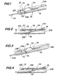
- Figure 1 is an isometric view of the distal end of one catheter of the invention and shown after it has been mounted on a conventional guide-wire by a connector at the distal end of the catheter;
- Figure 2 is a longitudinal sectional view of the distal end of the catheter shown in Figure 1;
- Figure 3 is an isometric view of the distal end of a bevelled distal end catheter of the invention and shown after it has been mounted on a conventional guide-wire by a "helical-cut" connector forming a portion of the distal end of the catheter;
- Figure 4 is a longitudinal sectional view of the distal end of the catheter shown in Figure 3;
- Figure 5 is an isometric view of the distal end of another catheter of the invention and shown after it has been mounted on a conventional guide-wire by a "pigtail" connector forming a portion of the distal end of the catheter;
- Figure 6 is a longitudinal sectional view of the distal end of the catheter shown in Figure 5;
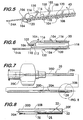
- Figure 7 is a top plan view of the catheter shown in Figure 1 drawn to a reduced scale;
- Figure 8 is an enlarged top plan view of the portion of the catheter shown within the area bounded by the circular broken line in Figure 7;
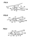
- Figure 9 is an isometric view of the distal end of the catheter shown in Figure 1 during an initial step in the mounting of the catheter on the guide-wire;
- Figure 10 is an isometric view similar to Figure 9 showing the distal end of the catheter of Figure 1 during an intermediate step in the mounting of the catheter on the guide-wire;
- Figure 11 is an isometric view similar to Figures 9 and 10 showing the distal end of the catheter of Figure 1 at a still later step in the mounting of the catheter on the guide-wire;
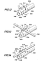
- Figure 12 is an isometric view of the distal end of another catheter not comprised within the scope of the claims ;
- Figure 13 is an isometric view similar to Figure 12 showing the distal end of the catheter of Figure 12 during an initial step in the mounting of the catheter on a guide-wire; and
- Figure 14 is an isometric view similar to Figures 12 and 13 showing the distal end of the catheter of Figure 12 after the catheter has been mounted on the catheter on the guide-wire.
- There is shown at 20 in Figure 1 the distal end of a tubular instrument, such as an infusate catheter for use in a intravascular revascularisation system and having a
connector 22 constructed in accordance with one embodiment of this invention for quickly and easily securing thecatheter 20 onto a conventional guide-wire 24 without requiring access to either end of the guide-wire. - Before discussing the details of the
connector 22, it should be pointed out that the subject invention can be used with any type of tubular instrument, be it a catheter or otherwise, that is arranged to be extended along a guide-wire or other elongated guide member into the body of a living being to a desired location and without requiring access to either end of the guide-wire or other elongated guide member. In the embodiments shown herein the guide-wire 24 is shown as being a tubular member, but can, if desired be a solid wire. - The infusate catheter whose distal end is shown in Fig. 1 is shown fully in the plan view of Fig. 7 and is merely exemplary of any type of catheter or tubular instrument for which the subject invention has application and utility, e.g., an angiographic catheter. As best seen in Fig. 7 the
catheter 20 basically comprises an elongatedtubular body 20A terminating at adistal end 20B at which theconnector 22 of the subject invention is located. The opposite or proximal end of thecatheter 22 is in the form of an enlarged hub orconnector 20C for connection to the associated components of the revascularization system (not shown). Acentral passageway 20D extends through the catheter and terminates at an openfree end 20E (Figs. 7 and 1). In the exemplary embodiment ofcatheter 20, thepassageway 20D is arranged to carry an infusate liquid therethrough for ejection via opening 20E into the portion of the vessel being revascularized or diagnosed. - Turning now to Fig. 1 the details of the
connector 22 will now be considered. As can be seen the connector is in the form of ahelical channel 28 cut into thewall 30 of the catheter at thedistal end portion 20B so that it is in communication with theinterior passageway 20D of the catheter along the entire length of the channel. Thechannel 28 may be of fixed or variable pitch and includes a widened or flaredmouth 32 where it meets or merges with the openfree end 20D of the catheter. It is through this mouth that the guide-wire is inserted into the channel. The proximal end of thechannel 28 terminates in an elongated slot orexit window 34 that is also in communication with theinterior passageway 20D. It is through thewindow 34 that the guide-wire exits the channel. Thus, the channel forms a path into which the guide-wire can be inserted to slidingly connect the catheter to the guide-wire. As will be discussed in detail to follow, the path is constructed so that the entry of the guide-wire into and through it can be facilitated easily, quickly and reliably with only a slight twisting action. - In accordance with one preferred aspect of this invention the material making up the catheter is preferably resilient so that the guide-
wire 24 can be extended into themouth 32 of the channel and then into contiguous portion of thechannel 28, whereupon the channel flexes open somewhat to enable the guide-wire to pass therethrough to exit from thewindow 34. As the guide-wire moves proximally along the channel to thewindow 34, portions for the channel distally of the guide wire flexes back to the initial position, whereupon when the guide-wire is within the window, the channel will have assumed its unflexed or normally closed condition. It should, however, be pointed out at this juncture that the catheter or the material forming slot need not be resilient, so long as the slot can accommodate the guide-wire therein to enable it to slide with respect thereto, as will be described later. - In order to facilitate the exit of the guide-
wire 24 from thechannel 28 at thewindow 34 and to ensure that the guide-wire extends closely parallel to the outer surface of the catheter from its exit point proximally, an elongate recess ordepression 36 is formed in thewall 30 of thecatheter 20 immediately proximally of thewindow 34. Therecess 36 extends along an axis parallel to the longitudinal axis of the catheter and, as best seen in Fig. 2, inclines upward from its lowest point where it merges with the proximal end of thewindow 34 to the point where it terminates at the outer circular surface of the catheter proximally of the window. - In the exemplary embodiment shown the outer diameter of the catheter is approximately 1,27 mm (0.05 inch). The
spiral channel 20 forms at least one complete revolution about the periphery of the catheter so that theentry mouth 32 is axially aligned with theexit window 34. The width of the entrance mouth is approximately 0,62 mm (0.025 inch). The width of the exit window is greater than the width of thechannel 28, e.g., 0.02 inch versus 0 to 0.015 inch. The length of thechannel 28 measured longitudinally from theopen end 20E of the catheter to the proximal end of the window 34 (i.e., the lowest point of the recess 36) is approximately 6,2 mm (0.25 inch). - In order to enable the user of the catheter to orient it in the desired rotational attitude for mounting onto the guide-wire, a process to be discussed in detail later, an indicator marker or indicia, such as an
arrow 38, is provided on the catheter aligned with the flaredmouth 32 so that the user of the catheter can readily determine the location of the channel'smouth 32 by viewing theindicator arrow 38. - The mounting of the
catheter 20 on the guide-wire 24 will now be discussed with reference to Figs. 9 - 11. It is assumed that the guide-wire is already in place so that its distal end (not shown) is located at some internal situs within the body of the being, while its proximal end is located outside the body of the being, with some intermediate portion, designated by thereference number 24A herein, also being located outside the body of the being distally of the proximal end of the guide-wire. It is at this intermediate position that thecatheter 20 is mounted on the guide-wire using theconnector 22. It should be pointed out at this juncture that while theportion 24A of the guide-wire is preferably outside the body of the being, such an arrangement is not required. In this regard in some medical applications theguide wire portion 24A where the catheter is to be connected may be located internally of the being and access provided to it via a natural body orifice or opening or through some surgically formed opening. - In any case, as best seen in Fig. 9 the
catheter 20 is oriented or twisted so that theentry mouth 32 at the distal end of the channel is aligned with theportion 24A of the guide-wire 24. The arrow indicia 38 facilitates the correct orientation alignment procedure. Once aligned the distal end of thecatheter 20 is moved in a lateral direction (e.g., from the side of the guide-wire) toward it (or the guide-wire is moved toward the catheter) so that the guide-wire portion 24A enters into the mouth of thechannel 116. Then the catheter is twisted or rotated in the direction shown byarrow 40 to cause the guide-wire portion 24A to enter into the contiguous portion of thechannel 28, whereupon the channel flexes open, as described earlier. Continued twisting of the catheter in the direction ofarrow 40 causes the guide-wire to move further down the channel as shown in Fig. 11. Continued twisting of the catheter with respect to the guide-wire in the direction ofarrow 40 eventually brings the guide-wire portion 24A into theexit window 32, as shown in Figs. 1 and 2, whereupon the guide-wire portion 24 exits the window and is guided upward by theinclined recess 36 until it is generally parallel to the outer surface of the catheter 20 (as best seen in Fig. 1). Once this has been accomplished, the catheter can be slid or moved in the distal direction along the guide-wire to bring the opendistal end 20E of the catheter to the desired position within the being's body, e.g., at a situs of the atherosclerotic deposit to be removed. - In Figs. 3 and 4 there is shown an alternative embodiment of a catheter 20' constructed in accordance with this invention. The catheter 20' is in all material respects identical to the
catheter 20, except for the shape of its distal end. Thus, in the interest of brevity the details of the construction and the operation of the catheter 20' will not be reiterated and the same reference numbers will be given to the common components. As can be seen in Figs. 3 and 4 the distal end of the catheter 20' includes abeveled end 20E'. The entry mouth to thechannel 28 is located on the most proximal portion of thebeveled end 20E' for initial receipt of the guide-wire portion 24A therein. - In Figs. 5 and 6 there is shown another embodiment of a
catheter 100 constructed in accordance with this invention. Thecatheter 100 also includes a connector 102 (to be described in detail hereinafter) for facilitating the mounting of the catheter on aportion 24A of the guide-wire from a lateral or side direction and without requiring access to either end of the guide-wire. However, unlike the embodiments of Figs. 1 - 4, theconnector 102 of thecatheter 100 is located externally to the outer surface of the distal end of thecatheter 100 to form the path or channel for the guide-wire therebetween. - The
connector 102 basically comprises a helical wire having pluralconsecutive helices 104 and terminating at one end in adistal end portion 106 and at the opposite orproximal end portion 108. Thedistal end portion 108 is linear and is centrally disposed within the helices 104 (See Fig. 6). The distal end portion is arranged to be fixedly secured in acentral bore 110 in the distal end of thecatheter 100. As can be seen the distal end of the catheter is closed, e.g., it includes a dome-shapedend wall 112 into which thebore 110 extends. Since the end of thecatheter 100 is closed, if it is to be used as an infusating device it includes plural outlet ports oropenings 116 extending through thesidewall 30 of the distal end portion and in communication with thecentral passageway 118 of the catheter. Thehelices 104 extend backward from thedistal end portion 106 of theconnector 102 and about the periphery of the outer surface of thecatheter 100 to form an annular space orchannel 120 therebetween. The thickness of the channel is just slightly greater than the outside diameter of the guide-wire (for reasons to be explained later). Theproximal end portion 108 terminates in a somewhat bulbous free end 122 which is also spaced from the outer surface of the catheter and which forms the entry mouth for thechannel 120. Theconnector 102 may be formed of any suitable biocompatible material, e.g., stainless steel, plastic, etc. - The mounting of the
catheter 100 on the guide-wire portion 24A is accomplished by orienting or aligning thecatheter 100 so that the guide-wire portion can be inserted into the entry mouth, i.e., the space between the bulbous distal free end 122 of theconnector 102 and the outer surface of thecatheter 100. Once aligned the distal end of thecatheter 100 is moved in a lateral direction (e.g., from the side of the guide-wire) toward it (or the guide-wire is moved toward the catheter) so that the guide-wire portion 24A enters into the mouth of the channel120. Then thecatheter 100 is twisted or rotated in the direction shown byarrow 40 to cause the guide-wire portion 24A to enter into the contiguous portion of thechannel 120, i.e., the helical portion defined by the helix closest to the free end 122. Continued twisting of the catheter in the direction ofarrow 40 causes the guide-wire to move further down the channel, guided by thehelices 104 until it exits from the channel at the distalmost helix 104. At this time the guide-wire will be within the confines of the channel and disposed parallel to and very closely adjacent to the outer surface of the catheter. Once this has been accomplished, thecatheter 100 can be slid or moved in the distal direction along the guide-wire 24 to bring the distal end of the catheter to the desired position within the being's body, e.g., at a situs of the atherosclerotic deposit to be removed. - In accordance with one preferred aspect of this invention the diameter of the wire making up the
connector 102 is quite small, e.g. 0,254 mm (0.010 inch), and the thickness of spacing between the inner surfaces of the connector'shelices 102 and the outer surface of the catheter 100 (i.e., the thickness of the annular channel 120) is just slightly larger than the outside diameter of the catheter. Thus, thecatheter 100 with theconnector 102 thereon will still exhibit a small crossing diameter (albeit somewhat greater than a comparable diametrically sized catheter making use of the connectors like shown in Figs. 1 - 4). - In Figs. 12-14 there is shown yet another alternative embodiment of a
catheter 200 not comprised within the scope of the claims. Thecatheter 200 is similar to thecatheter 20 in that it is a hollow tubular member having acentral passageway 20D terminating at an opendistal end 20E, yet is also similar to thecatheter 100 in thatcatheter 200 includes an externally locatedconnector 202. Theconnector 202 is like the other connectors described heretofore arranged to enable aguide wire 24 or other elongated guide member to be readily connected to the catheter by inserting it into a path (to be described hereinafter) by a twisting action, whereupon the catheter or other instrument can be slid along the guide-wire or other elongated guide member, yet is resistant to accidental disconnection. - As can be seen the
connector 202 basically comprises asleeve 204 formed of any biocompatible material, like those described heretofore, and having a pair offingers sleeve 204 includes a circular central passageway whose inside diameter is approximately the same as the outside diameter of the distal end portion of thecatheter 200 to accommodate that portion of the catheter extending therethrough. The sleeve is secured in place by any suitable means, e.g., an adhesive, by friction fit, etc. Moreover, the sleeve may be integrally formed on the distal end portion of the catheter. In fact, as will be appreciated from the discussion to follow, the use of a sleeve may be eliminated if the connector is formed integrally with the catheter. In such an arrangement, all that is required is that distal end of the catheter include thefingers - Each of the
fingers catheter 200. Each of the fingers includes an overhanging, e.g., arcuate,free end 210. The free end of the respective fingers are directed in opposed directions to each other, i.e., they are directed so that they face each other but are offset from each other in the longitudinal direction. In particular, thefree end 210 of thefinger 206 is directed from one side of thecatheter 200 towards thefree end 210 of thefinger 208 on the other side of the catheter. Thefingers catheter 200 so that thefree end 210 of thefinger 206 and thefree end 210 of thefinger 208 each form a respective portion of a channel orpath 212 between them and the portion of the sleeve from which they project (or from the portion of the catheter from which they project if no sleeve is utilized, e.g., the fingers are formed integrally with thecatheter 200. - In the preferred embodiment shown herein the
path 212 is of a generally circular cross-section and extends linearly along the longitudinal axis of the catheter immediately adjacent the outer surface of thesleeve 204. It is in this channel orpath 214 that the guide-wire portion 24A of the guide-wire 24 is arranged to be inserted to slidingly mount the catheter on the guide-wire. In accordance with a preferred embodiment of this invention the free ends 210 of thefingers channel 212 is provided by the space orgap 214 between thefingers - In order to minimize the crossing-diameter of the
catheter 200, thefingers catheter 200 as short as possible, while still enabling the guide-wire portion 24A to be held securely in thepath 212 for sliding movement resistant to accidental disconnection. Thus, in the preferred embodiment shown in the cross-sectional area of thechannel 212 is just slightly larger than the outside diameter of the guide-wire 24A and the fingers are very thin. - The connection of the
catheter 200 to the guide-wire portion 24A will now be described with reference to Figs. 13 and 14. As before, it is assumed that the guide-wire 24 is already in place so that its distal end (not shown) is located at some internal situs within the body of the being, while its proximal end is located outside the body of the being, with theintermediate portion 24A of the guide wire also being located outside the body of the being distally of the proximal end of the guide-wire. As pointed out earlier while theportion 24A of the guide-wire is preferably outside the body of the being, such an arrangement is not required. In this regard in some medical applications theguide wire portion 24A where the catheter is to be connected may be located internally of the being and access provided to it via a natural body orifice or opening or through some surgically formed opening. - In any case, as best seen in Fig.13 the
catheter 202 is oriented so that the entry mouth orgap 214 of thepath 212 at the distal end of the channel is aligned with theportion 24A of the guide-wire 24, e.g., the longitudinal axis of the guide-wire portion 24A is perpendicular to the longitudinal axis of thecatheter 200 and is between the fingers forming the gap. Once so aligned the distal end of thecatheter 20 is twisted about an axis perpendicular to the longitudinal axis of the catheter to bring the more distally located portion of the guide-wire portion 24A into thepath 212 under thefinger 206, while at the same time bringing the more proximally located portion of the guide-wire portion 24A into thepath 212 under thefinger 208 as shown in Fig. 14. This action completes the sliding securement of the catheter on the guide-wire 24. - Therefore, once the sliding securement has been accomplished, the
catheter 200 can be slid or moved in the distal direction along the guide-wire 24 to bring the opendistal end 20E of the catheter to the desired position within the being's body, e.g., at a situs of the atherosclerotic deposit to be removed. - It should be pointed out at this juncture that while the foregoing discussion has described the twisting of the catheter or other tubular instrument with respect to the guide-wire or other elongated guide member to releasably secure the two together, that methodology is not the only method for achieving their releasably securement. Thus, as will be appreciated by those skilled in the art, the guide-wire or other elongated guide member can be twisted with respect to the catheter or other tubular instrument to cause the guide-wire or other tubular instrument to be introduced into the path for holding the two together.
- It should also be pointed out that while the foregoing discussion has described catheters or other tubular instruments with the various types of connectors forming a portion thereof, it should be clear that connectors, per se, may be constructed in accordance for mounting, e.g., retrofitting, to existing catheters or other tubular instruments. Thus, the subject invention not only contemplates catheters or other elongated tubular instruments including connectors for connecting the catheters or other tubular instruments to guide-wires or other elongated guide member, but also contemplates connectors, per se, for use with conventional catheters to achieve those ends.
Claims (13)
- A medical device comprising a tubular instrument (20; 20'; 100;) such as a catheter and an elongate guide element (24) such as a guide wire, each having a distal end receivable in the lumen of a body of a living being, and a proximal end, the instrument having at its distal end a connector portion (22; 102;) defining a helical path (28; 120), wherein the instrument (20; 20'; 100;) can be engaged from a lateral direction by a longitudinal portion (24A) of the element (24) by a twisting action and retained therein without requiring access to either end of the element.
- A device according to Claim 1, wherein the path (28) is a channel in a wall portion of the connector (20) at the distal end of the instrument.
- A device according to Claim 2, wherein the connector (20) has an opening (34) at the proximal end through which the guide element (24) passes.
- A device according to Claim 3, wherein the channel (28) is shaped so that the guide element (24) extends through the opening (20E) in the distal end of the connector (22) and out of the opening (34) at the proximal end of the channel (28).
- A device according to any of Claims 2 to 4, wherein the channel has an outwardly flared mouth (32) to facilitate insertion of the guide element (24) into the channel (28).
- A device according to any of Claims 2 to 5, wherein the helical path (28) of the channel is of fixed or variable pitch.
- A device according to any preceding Claim, wherein the opening in the distal end of the instrument is beveled
- A device according to any of Claims 1 to 7, wherein the tubular instrument (20) is a catheter having an outer diameter of about 1.27 mm (0.05 inch) having a path (28) in the form of a spiral channel axially aligned with an exit window (34), and which measures about 6.2 mm (0.25 inch) long, having an entrance mouth being 0.62 mm (0.025 inch long) and the window (34) having a width greater than that of the channel (28).
- A device according to Claim 1, wherein the connector comprises helical wire (104) having a distal end and a proximal end, the distal end of the helical wire being secured to the distal end portion of the instrument (110), the proximal end of the helical wire being free and spaced slightly from the instrument (110) to form a mouth for the path (120) into which the guide element (24) can be inserted.
- A device according to Claim 9, wherein the channel is arranged so that when the instrument (110) is in place on the guide element (34), the guide element extends between the helical wire (104) and the instrument (110) and out of the proximal end of the channel.
- A device (100) according to Claim 9 or 10, wherein the helical wire (104) has a diameter of 0.254 mm (0.01 inch) and the thickness between the helices (102) and the catheter (100) is just slightly larger than the outside diameter of the catheter (110).
- A method of mounting a tubular instrument as defined in any preceding Claim on an elongate guide element such as a guidewire as defined in any preceding Claim, comprising moving the instrument laterally of a longitudinal portion of the guide element and twisting the instrument relative to the element to cause the longitudinal portion to enter the helical path and thereby engage the element without requiring access to either end of the guide element.
- A method according to Claim 12, wherein the distal end of the guide element is within a lumen and including the additional step of sliding the tubular instrument along the elongate element to a desired location within the lumen.
Applications Claiming Priority (3)
| Application Number | Priority Date | Filing Date | Title |
|---|---|---|---|
| US523077 | 2000-03-10 | ||
| US09/523,077 US6569151B1 (en) | 2000-03-10 | 2000-03-10 | Device for connecting a catheter or other tubular member onto a guide-wire without access to the ends of the guide-wire |
| PCT/US2001/007318 WO2001068177A1 (en) | 2000-03-10 | 2001-03-08 | Device for connecting a catheter onto a guide-wire |
Publications (2)
| Publication Number | Publication Date |
|---|---|
| EP1278570A1 EP1278570A1 (en) | 2003-01-29 |
| EP1278570B1 true EP1278570B1 (en) | 2006-10-25 |
Family
ID=24083558
Family Applications (1)
| Application Number | Title | Priority Date | Filing Date |
|---|---|---|---|
| EP01918421A Expired - Lifetime EP1278570B1 (en) | 2000-03-10 | 2001-03-08 | Device for connecting a catheter onto a guide-wire |
Country Status (8)
| Country | Link |
|---|---|
| US (2) | US6569151B1 (en) |
| EP (1) | EP1278570B1 (en) |
| JP (1) | JP3860033B2 (en) |
| AT (1) | ATE343409T1 (en) |
| AU (1) | AU2001245501A1 (en) |
| CA (1) | CA2402137C (en) |
| DE (1) | DE60124086D1 (en) |
| WO (1) | WO2001068177A1 (en) |
Cited By (1)
| Publication number | Priority date | Publication date | Assignee | Title |
|---|---|---|---|---|
| US8157766B2 (en) | 2005-09-01 | 2012-04-17 | Medrad, Inc. | Torqueable kink-resistant guidewire |
Families Citing this family (49)
| Publication number | Priority date | Publication date | Assignee | Title |
|---|---|---|---|---|
| US7744588B2 (en) * | 2002-05-21 | 2010-06-29 | Kensey Nash Corporation | Tool for facilitating the connecting of a catheter or other tubular member onto a guide-wire without access to the ends of the guide wire |
| US20050075647A1 (en) * | 2000-03-10 | 2005-04-07 | Greg Walters | Tool for facilitating the connecting of a catheter or other tubular member onto a guide-wire without access to the ends of the guide-wire |
| DE10153842A1 (en) * | 2001-10-24 | 2003-05-08 | Biotronik Mess & Therapieg | electrode assembly |
| JP4321019B2 (en) * | 2002-08-01 | 2009-08-26 | 株式会社カネカ | Suction catheter |
| US6851424B2 (en) * | 2002-08-08 | 2005-02-08 | Scimed Life Systems, Inc. | Mouthguard having device securing tab |
| US7172577B2 (en) * | 2002-08-09 | 2007-02-06 | Boston Scientific Scimed, Inc. | Guidewire locking device and method |
| EP1680170B1 (en) * | 2003-10-16 | 2012-01-25 | Minvasys | Catheter system for stenting bifurcated vessels |
| US7695508B2 (en) * | 2003-10-16 | 2010-04-13 | Minvasys Sa | Catheter system for stenting bifurcated vessels |
| US7217246B1 (en) * | 2004-06-17 | 2007-05-15 | Biomet Sports Medicine, Inc. | Method and apparatus for retaining a fixation pin to a cannula |
| US7828751B2 (en) * | 2004-06-17 | 2010-11-09 | Biomet Sports Medicine, Llc | Method and apparatus for retaining a fixation pin to a cannula |
| US7618015B2 (en) * | 2005-02-15 | 2009-11-17 | David Brian Jahnz | Easy set-up pole and support system |
| US9005138B2 (en) * | 2005-08-25 | 2015-04-14 | Cook Medical Technologies Llc | Wire guide having distal coupling tip |
| US8075497B2 (en) * | 2005-08-25 | 2011-12-13 | Cook Medical Technologies Llc | Wire guide having distal coupling tip |
| US8608703B2 (en) | 2007-06-12 | 2013-12-17 | Medrad, Inc. | Infusion flow guidewire system |
| US7758565B2 (en) * | 2005-10-18 | 2010-07-20 | Cook Incorporated | Identifiable wire guide |
| US8137291B2 (en) * | 2005-10-27 | 2012-03-20 | Cook Medical Technologies Llc | Wire guide having distal coupling tip |
| US7731693B2 (en) * | 2005-10-27 | 2010-06-08 | Cook Incorporated | Coupling wire guide |
| US7811238B2 (en) * | 2006-01-13 | 2010-10-12 | Cook Incorporated | Wire guide having distal coupling tip |
| US7785275B2 (en) * | 2006-01-31 | 2010-08-31 | Cook Incorporated | Wire guide having distal coupling tip |
| US7798980B2 (en) * | 2006-01-31 | 2010-09-21 | Cook Incorporated | Wire guide having distal coupling tip for attachment to a previously introduced wire guide |
| US20070191790A1 (en) * | 2006-02-16 | 2007-08-16 | Cook Incorporated | Wire guide having distal coupling tip |
| US8133190B2 (en) * | 2006-06-22 | 2012-03-13 | Cook Medical Technologies Llc | Weldable wire guide with distal coupling tip |
| CA2673557C (en) * | 2006-12-22 | 2013-02-12 | Wilson-Cook Medical Inc. | Splittable wire guide |
| US20080306453A1 (en) * | 2007-06-06 | 2008-12-11 | Cook Incorporated | Coupling wire guide and method for making same |
| US9474546B1 (en) | 2008-04-18 | 2016-10-25 | Advanced Bionics Ag | Pre-curved electrode array insertion tools |
| US20100152613A1 (en) * | 2008-12-11 | 2010-06-17 | Shawn Ryan | Clip for handling an endoscopic device |
| US9408595B2 (en) * | 2009-08-31 | 2016-08-09 | St. Jude Medical Puerto Rico Llc | Monorail system for vascular closure device and methods |
| US9216299B2 (en) | 2009-10-21 | 2015-12-22 | Thomas J. Wolfe | Electromagnetic pathologic lesion treatment system and method |
| WO2011050085A2 (en) * | 2009-10-21 | 2011-04-28 | Wolfe Thomas J | Electromagnetic thrombus treatment system and method |
| US8827927B2 (en) * | 2010-04-05 | 2014-09-09 | Cook Medical Technologies Llc | Hub for loop tip devices |
| US8753352B2 (en) | 2010-06-25 | 2014-06-17 | Advanced Bionics Ag | Tools, systems, and methods for inserting a pre-curved electrode array portion of a lead into a bodily orifice |
| US8753353B2 (en) | 2010-06-25 | 2014-06-17 | Advanced Bionics Ag | Tools, systems, and methods for inserting an electrode array portion of a lead into a bodily orifice |
| EP2603254A4 (en) | 2010-08-12 | 2016-08-24 | Boston Scient Ltd | SYSTEM OF INFUSION FLOW AND FLUID COUPLING |
| US8747428B2 (en) * | 2012-01-12 | 2014-06-10 | Fischell Innovations, Llc | Carotid sheath with entry and tracking rapid exchange dilators and method of use |
| WO2014112518A1 (en) | 2013-01-21 | 2014-07-24 | 富士フイルム株式会社 | Tissue sampling device |
| JP6097826B2 (en) * | 2013-05-27 | 2017-03-15 | 富士フイルム株式会社 | Tissue collection device |
| EP3145423B1 (en) * | 2014-05-20 | 2020-12-30 | Muffin Incorporated | Aneurysm stop pressure system |
| US10376308B2 (en) | 2015-02-05 | 2019-08-13 | Axon Therapies, Inc. | Devices and methods for treatment of heart failure by splanchnic nerve ablation |
| JP6709033B2 (en) * | 2015-10-13 | 2020-06-10 | 泉工医科工業株式会社 | Tube retainer |
| JP6722907B2 (en) * | 2016-03-23 | 2020-07-15 | 国立大学法人 東京大学 | Endoscope catheter |
| CN114711957A (en) | 2016-07-29 | 2022-07-08 | 阿克松疗法公司 | Devices, systems, and methods for treating heart failure through cardiac nerve ablation |
| US11083503B2 (en) | 2016-09-22 | 2021-08-10 | Globus Medical, Inc. | Systems and methods for intramedullary nail implantation |
| US10492803B2 (en) | 2016-09-22 | 2019-12-03 | Globus Medical, Inc. | Systems and methods for intramedullary nail implantation |
| WO2019066728A1 (en) * | 2017-09-30 | 2019-04-04 | Tay Hsien Tsung | Obturator, sheath and method for using same |
| US10561461B2 (en) | 2017-12-17 | 2020-02-18 | Axon Therapies, Inc. | Methods and devices for endovascular ablation of a splanchnic nerve |
| EP4406567B1 (en) | 2018-01-26 | 2026-01-28 | Axon Vascular, Inc. | Device for endovascular ablation of a splanchnic nerve |
| WO2020257763A1 (en) | 2019-06-20 | 2020-12-24 | Axon Therapies, Inc. | Methods and devices for endovascular ablation of a splanchnic nerve |
| US11633219B2 (en) | 2019-06-26 | 2023-04-25 | Globus Medical, Inc. | Fenestrated pedicle nail |
| EP4181999A4 (en) * | 2021-02-15 | 2024-03-06 | Teleflex Life Sciences Limited | Support catheters and associated loading components |
Family Cites Families (13)
| Publication number | Priority date | Publication date | Assignee | Title |
|---|---|---|---|---|
| US4230109A (en) * | 1978-08-21 | 1980-10-28 | Alan Geiss | Apparatus for securing couplings of intravenous and intra-arterial access systems |
| US4771782A (en) * | 1986-11-14 | 1988-09-20 | Millar Instruments, Inc. | Method and assembly for introducing multiple catheters into a biological vessel |
| FR2622117B1 (en) | 1987-10-27 | 1997-01-31 | Cordis Sa | CANNULA AND PEN CATHETER INTRODUCER |
| US5016559A (en) * | 1989-06-30 | 1991-05-21 | Vada J. Larson | Bookmark having integral pencil holder |
| US5290310A (en) * | 1991-10-30 | 1994-03-01 | Howmedica, Inc. | Hemostatic implant introducer |
| US5267958A (en) | 1992-03-30 | 1993-12-07 | Medtronic, Inc. | Exchange catheter having exterior guide wire loops |
| AU4763296A (en) * | 1995-02-03 | 1996-08-21 | Inbae Yoon | Cannula with distal end valve |
| US5575771A (en) * | 1995-04-24 | 1996-11-19 | Walinsky; Paul | Balloon catheter with external guidewire |
| US6022336A (en) | 1996-05-20 | 2000-02-08 | Percusurge, Inc. | Catheter system for emboli containment |
| US6007517A (en) | 1996-08-19 | 1999-12-28 | Anderson; R. David | Rapid exchange/perfusion angioplasty catheter |
| US6156062A (en) * | 1997-12-03 | 2000-12-05 | Ave Connaught | Helically wrapped interlocking stent |
| US6086543A (en) * | 1998-06-24 | 2000-07-11 | Rubicor Medical, Inc. | Fine needle and core biopsy devices and methods |
| US6783520B1 (en) * | 1999-12-04 | 2004-08-31 | Fresenius Usa, Inc. | Connector holder for a fluid connection system |
-
2000
- 2000-03-10 US US09/523,077 patent/US6569151B1/en not_active Expired - Lifetime
-
2001
- 2001-03-08 JP JP2001566738A patent/JP3860033B2/en not_active Expired - Fee Related
- 2001-03-08 DE DE60124086T patent/DE60124086D1/en not_active Expired - Lifetime
- 2001-03-08 EP EP01918421A patent/EP1278570B1/en not_active Expired - Lifetime
- 2001-03-08 CA CA002402137A patent/CA2402137C/en not_active Expired - Fee Related
- 2001-03-08 AU AU2001245501A patent/AU2001245501A1/en not_active Abandoned
- 2001-03-08 AT AT01918421T patent/ATE343409T1/en not_active IP Right Cessation
- 2001-03-08 WO PCT/US2001/007318 patent/WO2001068177A1/en not_active Ceased
-
2003
- 2003-01-28 US US10/352,572 patent/US6926707B2/en not_active Expired - Lifetime
Cited By (1)
| Publication number | Priority date | Publication date | Assignee | Title |
|---|---|---|---|---|
| US8157766B2 (en) | 2005-09-01 | 2012-04-17 | Medrad, Inc. | Torqueable kink-resistant guidewire |
Also Published As
| Publication number | Publication date |
|---|---|
| EP1278570A1 (en) | 2003-01-29 |
| WO2001068177A1 (en) | 2001-09-20 |
| US6569151B1 (en) | 2003-05-27 |
| ATE343409T1 (en) | 2006-11-15 |
| JP3860033B2 (en) | 2006-12-20 |
| JP2003526481A (en) | 2003-09-09 |
| US20030120213A1 (en) | 2003-06-26 |
| CA2402137C (en) | 2008-05-20 |
| US6926707B2 (en) | 2005-08-09 |
| WO2001068177A9 (en) | 2003-03-06 |
| DE60124086D1 (en) | 2006-12-07 |
| AU2001245501A1 (en) | 2001-09-24 |
| CA2402137A1 (en) | 2001-09-20 |
Similar Documents
| Publication | Publication Date | Title |
|---|---|---|
| EP1278570B1 (en) | Device for connecting a catheter onto a guide-wire | |
| US6517518B2 (en) | Tool for facilitating the connecting of a catheter or other tubular member onto a guide-wire without access to the ends of the guide-wire | |
| US7713261B2 (en) | Instrument including connector for facilitating connection onto a guide-wire without access to the ends of the guide-wire and method of use | |
| US20050075647A1 (en) | Tool for facilitating the connecting of a catheter or other tubular member onto a guide-wire without access to the ends of the guide-wire | |
| US6869417B1 (en) | Tool for facilitating the connecting of a catheter or other tubular member onto a guide-wire without access to the ends of the guide-wire | |
| US4769005A (en) | Selective catheter guide | |
| US5827202A (en) | Guide wire dispenser apparatus and method | |
| EP1651299B1 (en) | Catheter tunneler adapter | |
| US6461336B1 (en) | Cardiological medical equipment | |
| CA2257624C (en) | Guide wire dispenser apparatus and method | |
| US20190240462A1 (en) | Guidewire with adjustable stiffness | |
| US8986281B2 (en) | Anti-thrombogenic catheter and method | |
| US20060015130A1 (en) | Catheter tunneler adapter | |
| US10881831B2 (en) | Endoscopic basket delivery catheter | |
| US20090062769A1 (en) | Rapid exchange catheter converter | |
| KR20230066616A (en) | Thrombus removal method and related devices and systems |
Legal Events
| Date | Code | Title | Description |
|---|---|---|---|
| PUAI | Public reference made under article 153(3) epc to a published international application that has entered the european phase |
Free format text: ORIGINAL CODE: 0009012 |
|
| AK | Designated contracting states |
Designated state(s): AT BE CH CY DE DK ES FI FR GB GR IE IT LI LU MC NL PT SE TR |
|
| AX | Request for extension of the european patent |
Extension state: AL LT LV MK RO SI |
|
| 17P | Request for examination filed |
Effective date: 20021025 |
|
| GRAP | Despatch of communication of intention to grant a patent |
Free format text: ORIGINAL CODE: EPIDOSNIGR1 |
|
| GRAS | Grant fee paid |
Free format text: ORIGINAL CODE: EPIDOSNIGR3 |
|
| GRAA | (expected) grant |
Free format text: ORIGINAL CODE: 0009210 |
|
| AK | Designated contracting states |
Kind code of ref document: B1 Designated state(s): AT BE CH CY DE DK ES FI FR GB GR IE IT LI LU MC NL PT SE TR |
|
| PG25 | Lapsed in a contracting state [announced via postgrant information from national office to epo] |
Ref country code: IT Free format text: LAPSE BECAUSE OF FAILURE TO SUBMIT A TRANSLATION OF THE DESCRIPTION OR TO PAY THE FEE WITHIN THE PRESCRIBED TIME-LIMIT;WARNING: LAPSES OF ITALIAN PATENTS WITH EFFECTIVE DATE BEFORE 2007 MAY HAVE OCCURRED AT ANY TIME BEFORE 2007. THE CORRECT EFFECTIVE DATE MAY BE DIFFERENT FROM THE ONE RECORDED. Effective date: 20061025 Ref country code: NL Free format text: LAPSE BECAUSE OF FAILURE TO SUBMIT A TRANSLATION OF THE DESCRIPTION OR TO PAY THE FEE WITHIN THE PRESCRIBED TIME-LIMIT Effective date: 20061025 Ref country code: AT Free format text: LAPSE BECAUSE OF FAILURE TO SUBMIT A TRANSLATION OF THE DESCRIPTION OR TO PAY THE FEE WITHIN THE PRESCRIBED TIME-LIMIT Effective date: 20061025 Ref country code: CH Free format text: LAPSE BECAUSE OF FAILURE TO SUBMIT A TRANSLATION OF THE DESCRIPTION OR TO PAY THE FEE WITHIN THE PRESCRIBED TIME-LIMIT Effective date: 20061025 Ref country code: BE Free format text: LAPSE BECAUSE OF FAILURE TO SUBMIT A TRANSLATION OF THE DESCRIPTION OR TO PAY THE FEE WITHIN THE PRESCRIBED TIME-LIMIT Effective date: 20061025 Ref country code: LI Free format text: LAPSE BECAUSE OF FAILURE TO SUBMIT A TRANSLATION OF THE DESCRIPTION OR TO PAY THE FEE WITHIN THE PRESCRIBED TIME-LIMIT Effective date: 20061025 Ref country code: FI Free format text: LAPSE BECAUSE OF FAILURE TO SUBMIT A TRANSLATION OF THE DESCRIPTION OR TO PAY THE FEE WITHIN THE PRESCRIBED TIME-LIMIT Effective date: 20061025 |
|
| REG | Reference to a national code |
Ref country code: GB Ref legal event code: FG4D |
|
| REG | Reference to a national code |
Ref country code: CH Ref legal event code: EP |
|
| REG | Reference to a national code |
Ref country code: IE Ref legal event code: FG4D |
|
| REF | Corresponds to: |
Ref document number: 60124086 Country of ref document: DE Date of ref document: 20061207 Kind code of ref document: P |
|
| PG25 | Lapsed in a contracting state [announced via postgrant information from national office to epo] |
Ref country code: DK Free format text: LAPSE BECAUSE OF FAILURE TO SUBMIT A TRANSLATION OF THE DESCRIPTION OR TO PAY THE FEE WITHIN THE PRESCRIBED TIME-LIMIT Effective date: 20070125 Ref country code: SE Free format text: LAPSE BECAUSE OF FAILURE TO SUBMIT A TRANSLATION OF THE DESCRIPTION OR TO PAY THE FEE WITHIN THE PRESCRIBED TIME-LIMIT Effective date: 20070125 |
|
| PG25 | Lapsed in a contracting state [announced via postgrant information from national office to epo] |
Ref country code: DE Free format text: LAPSE BECAUSE OF FAILURE TO SUBMIT A TRANSLATION OF THE DESCRIPTION OR TO PAY THE FEE WITHIN THE PRESCRIBED TIME-LIMIT Effective date: 20070126 |
|
| PG25 | Lapsed in a contracting state [announced via postgrant information from national office to epo] |
Ref country code: ES Free format text: LAPSE BECAUSE OF FAILURE TO SUBMIT A TRANSLATION OF THE DESCRIPTION OR TO PAY THE FEE WITHIN THE PRESCRIBED TIME-LIMIT Effective date: 20070205 |
|
| PG25 | Lapsed in a contracting state [announced via postgrant information from national office to epo] |
Ref country code: PT Free format text: LAPSE BECAUSE OF FAILURE TO SUBMIT A TRANSLATION OF THE DESCRIPTION OR TO PAY THE FEE WITHIN THE PRESCRIBED TIME-LIMIT Effective date: 20070326 |
|
| NLV1 | Nl: lapsed or annulled due to failure to fulfill the requirements of art. 29p and 29m of the patents act | ||
| REG | Reference to a national code |
Ref country code: CH Ref legal event code: PL |
|
| EN | Fr: translation not filed | ||
| PLBE | No opposition filed within time limit |
Free format text: ORIGINAL CODE: 0009261 |
|
| STAA | Information on the status of an ep patent application or granted ep patent |
Free format text: STATUS: NO OPPOSITION FILED WITHIN TIME LIMIT |
|
| 26N | No opposition filed |
Effective date: 20070726 |
|
| PG25 | Lapsed in a contracting state [announced via postgrant information from national office to epo] |
Ref country code: MC Free format text: LAPSE BECAUSE OF NON-PAYMENT OF DUE FEES Effective date: 20070331 |
|
| PG25 | Lapsed in a contracting state [announced via postgrant information from national office to epo] |
Ref country code: FR Free format text: LAPSE BECAUSE OF FAILURE TO SUBMIT A TRANSLATION OF THE DESCRIPTION OR TO PAY THE FEE WITHIN THE PRESCRIBED TIME-LIMIT Effective date: 20070608 Ref country code: GR Free format text: LAPSE BECAUSE OF FAILURE TO SUBMIT A TRANSLATION OF THE DESCRIPTION OR TO PAY THE FEE WITHIN THE PRESCRIBED TIME-LIMIT Effective date: 20070126 |
|
| PG25 | Lapsed in a contracting state [announced via postgrant information from national office to epo] |
Ref country code: FR Free format text: LAPSE BECAUSE OF FAILURE TO SUBMIT A TRANSLATION OF THE DESCRIPTION OR TO PAY THE FEE WITHIN THE PRESCRIBED TIME-LIMIT Effective date: 20061025 |
|
| PG25 | Lapsed in a contracting state [announced via postgrant information from national office to epo] |
Ref country code: CY Free format text: LAPSE BECAUSE OF FAILURE TO SUBMIT A TRANSLATION OF THE DESCRIPTION OR TO PAY THE FEE WITHIN THE PRESCRIBED TIME-LIMIT Effective date: 20061025 Ref country code: LU Free format text: LAPSE BECAUSE OF NON-PAYMENT OF DUE FEES Effective date: 20070308 |
|
| PG25 | Lapsed in a contracting state [announced via postgrant information from national office to epo] |
Ref country code: TR Free format text: LAPSE BECAUSE OF FAILURE TO SUBMIT A TRANSLATION OF THE DESCRIPTION OR TO PAY THE FEE WITHIN THE PRESCRIBED TIME-LIMIT Effective date: 20061025 |
|
| PGFP | Annual fee paid to national office [announced via postgrant information from national office to epo] |
Ref country code: IE Payment date: 20160309 Year of fee payment: 16 |
|
| PGFP | Annual fee paid to national office [announced via postgrant information from national office to epo] |
Ref country code: GB Payment date: 20160302 Year of fee payment: 16 |
|
| GBPC | Gb: european patent ceased through non-payment of renewal fee |
Effective date: 20170308 |
|
| REG | Reference to a national code |
Ref country code: IE Ref legal event code: MM4A |
|
| PG25 | Lapsed in a contracting state [announced via postgrant information from national office to epo] |
Ref country code: GB Free format text: LAPSE BECAUSE OF NON-PAYMENT OF DUE FEES Effective date: 20170308 Ref country code: IE Free format text: LAPSE BECAUSE OF NON-PAYMENT OF DUE FEES Effective date: 20170308 |