EP1278251B1 - Cooling arrangement on Case of Secondary Battery - Google Patents
Cooling arrangement on Case of Secondary Battery Download PDFInfo
- Publication number
- EP1278251B1 EP1278251B1 EP20020014060 EP02014060A EP1278251B1 EP 1278251 B1 EP1278251 B1 EP 1278251B1 EP 20020014060 EP20020014060 EP 20020014060 EP 02014060 A EP02014060 A EP 02014060A EP 1278251 B1 EP1278251 B1 EP 1278251B1
- Authority
- EP
- European Patent Office
- Prior art keywords
- battery case
- radiators
- secondary battery
- battery
- width direction
- Prior art date
- Legal status (The legal status is an assumption and is not a legal conclusion. Google has not performed a legal analysis and makes no representation as to the accuracy of the status listed.)
- Expired - Lifetime
Links
Images


Classifications
-
- H—ELECTRICITY
- H01—ELECTRIC ELEMENTS
- H01M—PROCESSES OR MEANS, e.g. BATTERIES, FOR THE DIRECT CONVERSION OF CHEMICAL ENERGY INTO ELECTRICAL ENERGY
- H01M10/00—Secondary cells; Manufacture thereof
- H01M10/60—Heating or cooling; Temperature control
- H01M10/61—Types of temperature control
- H01M10/613—Cooling or keeping cold
-
- H—ELECTRICITY
- H01—ELECTRIC ELEMENTS
- H01M—PROCESSES OR MEANS, e.g. BATTERIES, FOR THE DIRECT CONVERSION OF CHEMICAL ENERGY INTO ELECTRICAL ENERGY
- H01M10/00—Secondary cells; Manufacture thereof
- H01M10/60—Heating or cooling; Temperature control
- H01M10/62—Heating or cooling; Temperature control specially adapted for specific applications
- H01M10/625—Vehicles
-
- H—ELECTRICITY
- H01—ELECTRIC ELEMENTS
- H01M—PROCESSES OR MEANS, e.g. BATTERIES, FOR THE DIRECT CONVERSION OF CHEMICAL ENERGY INTO ELECTRICAL ENERGY
- H01M10/00—Secondary cells; Manufacture thereof
- H01M10/60—Heating or cooling; Temperature control
- H01M10/64—Heating or cooling; Temperature control characterised by the shape of the cells
- H01M10/647—Prismatic or flat cells, e.g. pouch cells
-
- H—ELECTRICITY
- H01—ELECTRIC ELEMENTS
- H01M—PROCESSES OR MEANS, e.g. BATTERIES, FOR THE DIRECT CONVERSION OF CHEMICAL ENERGY INTO ELECTRICAL ENERGY
- H01M10/00—Secondary cells; Manufacture thereof
- H01M10/60—Heating or cooling; Temperature control
- H01M10/65—Means for temperature control structurally associated with the cells
- H01M10/655—Solid structures for heat exchange or heat conduction
- H01M10/6551—Surfaces specially adapted for heat dissipation or radiation, e.g. fins or coatings
-
- H—ELECTRICITY
- H01—ELECTRIC ELEMENTS
- H01M—PROCESSES OR MEANS, e.g. BATTERIES, FOR THE DIRECT CONVERSION OF CHEMICAL ENERGY INTO ELECTRICAL ENERGY
- H01M10/00—Secondary cells; Manufacture thereof
- H01M10/60—Heating or cooling; Temperature control
- H01M10/65—Means for temperature control structurally associated with the cells
- H01M10/655—Solid structures for heat exchange or heat conduction
- H01M10/6554—Rods or plates
-
- H—ELECTRICITY
- H01—ELECTRIC ELEMENTS
- H01M—PROCESSES OR MEANS, e.g. BATTERIES, FOR THE DIRECT CONVERSION OF CHEMICAL ENERGY INTO ELECTRICAL ENERGY
- H01M10/00—Secondary cells; Manufacture thereof
- H01M10/60—Heating or cooling; Temperature control
- H01M10/65—Means for temperature control structurally associated with the cells
- H01M10/655—Solid structures for heat exchange or heat conduction
- H01M10/6556—Solid parts with flow channel passages or pipes for heat exchange
- H01M10/6557—Solid parts with flow channel passages or pipes for heat exchange arranged between the cells
-
- H—ELECTRICITY
- H01—ELECTRIC ELEMENTS
- H01M—PROCESSES OR MEANS, e.g. BATTERIES, FOR THE DIRECT CONVERSION OF CHEMICAL ENERGY INTO ELECTRICAL ENERGY
- H01M10/00—Secondary cells; Manufacture thereof
- H01M10/60—Heating or cooling; Temperature control
- H01M10/65—Means for temperature control structurally associated with the cells
- H01M10/656—Means for temperature control structurally associated with the cells characterised by the type of heat-exchange fluid
- H01M10/6561—Gases
-
- H—ELECTRICITY
- H01—ELECTRIC ELEMENTS
- H01M—PROCESSES OR MEANS, e.g. BATTERIES, FOR THE DIRECT CONVERSION OF CHEMICAL ENERGY INTO ELECTRICAL ENERGY
- H01M50/00—Constructional details or processes of manufacture of the non-active parts of electrochemical cells other than fuel cells, e.g. hybrid cells
- H01M50/10—Primary casings, jackets or wrappings of a single cell or a single battery
- H01M50/102—Primary casings, jackets or wrappings of a single cell or a single battery characterised by their shape or physical structure
- H01M50/112—Monobloc comprising multiple compartments
-
- Y—GENERAL TAGGING OF NEW TECHNOLOGICAL DEVELOPMENTS; GENERAL TAGGING OF CROSS-SECTIONAL TECHNOLOGIES SPANNING OVER SEVERAL SECTIONS OF THE IPC; TECHNICAL SUBJECTS COVERED BY FORMER USPC CROSS-REFERENCE ART COLLECTIONS [XRACs] AND DIGESTS
- Y02—TECHNOLOGIES OR APPLICATIONS FOR MITIGATION OR ADAPTATION AGAINST CLIMATE CHANGE
- Y02E—REDUCTION OF GREENHOUSE GAS [GHG] EMISSIONS, RELATED TO ENERGY GENERATION, TRANSMISSION OR DISTRIBUTION
- Y02E60/00—Enabling technologies; Technologies with a potential or indirect contribution to GHG emissions mitigation
- Y02E60/10—Energy storage using batteries
Definitions
- the present invention relates to a secondary battery used in an electric vehicle or the like. Specifically, the present invention relates to a thin rectangular-parallelepiped shaped secondary battery having an improved cooling efficiency.
- a secondary battery which can be repeatedly charged and discharged is used as a power source of a motor in various types of electric vehicles, for example, a hybrid electric vehicle or the like.
- a secondary battery when used in an electric vehicle, is required to have a large capacity of electricity and a high voltage. Therefore, a plurality of secondary batteries are combined to form a battery pack and the battery pack is mounted in a vehicle.
- FIG 13 is a perspective view showing an exemplary secondary battery 200 which forms a battery pack to be mounted in an electric vehicle.
- the secondary battery 200 has a battery case 50.
- the battery case 50 has a battery case body 51 formed into a thin rectangular-parallelepiped shape having an open top and a strip-like cover 53 for covering the open top of the battery case body 51.
- the thin rectangular-parallelepiped shaped battery case 50 has a small thickness D2, a height H greater than the thickness D2, and a width W greater than the height H.
- An inner space of the battery case body 51 is divided into, for example, six reaction chambers by five walls extending in the thickness D2 direction, equally spaced in the width W direction.
- Each of the reaction chambers contains a plurality of positive plates and a plurality of negative plates which extend in the width W direction of the battery case 50.
- the positive plates and the negative plates are provided, being insulated from each other by separators. All the positive plates in the reaction chamber are connected to a positive pole collector plate extending in the thickness D2 direction. All the negative plates in the reaction chamber are connected to a negative pole collector plate extending in the thickness D2 direction. The positive pole collector plate and the negative pole collector plate oppose each other within the reactive chamber with all the positive plates and the negative plates interposed therebetween. All the positive plates and the negative plates, and the collector plates are in contact with an electrolyte in the reaction chamber.
- a terminal 55a of the positive pole is provided on a side surface 51x of the battery case body 51 .
- This terminal 55a is serially connected to the positive pole collector plate positioned in the reaction chamber adjacent to the surface 51x.
- a terminal 55b of the negative pole is provided on another side surface 51y of the battery case body 51.
- This terminal 55b is serially connected to the collector plate of the negative pole positioned in the reaction chamber adjacent to the surface 51y.
- the positive pole collector plate and the negative pole collector plate are serially connected to the respective positive pole collector plate and the negative pole collector plate in an adjacent reaction chamber.
- a plurality of the secondary batteries 200 having the above-described structure are stacked side-by-side in the thickness D2 direction and connected in series or in parallel to each other to form a battery pack.
- the battery pack is mounted in an electric vehicle.
- the secondary battery 200 has a problem that, due to a reaction resistance caused by a battery reaction and component resistance caused by collecting electricity and connection between the components, a temperature in the reaction chamber rises and thus a temperature of the battery case 50 rises. Especially, when a large amount of current is charged and/or discharged, temperature of the battery case 50 rises significantly. If the temperature in the reaction chamber rises, battery reaction in the reaction chamber is weakened. Thus, cooling air is supplied and passed through the space between a pair of stacked secondary batteries in the height H direction (e.g., from the bottom to the top of the battery case 50 in Figure 13) to cool the battery case 50 of the secondary battery.
- a secondary battery 200 has ribs 54 which extend in the height H direction on each surface 51b along the width W direction of the battery case body 51 with a certain space therebetween in the width W direction for smoothly passing the cooling air through the spaces between the pair of the stacked secondary batteries.
- a number of protrusions 51c are provided on the surfaces 51b of the battery case body 51 to improve a resistance of the secondary battery 200 against pressure.
- the capacity of the secondary battery 200 is increased by increasing only the thickness D2 of the battery case 50 to increase the number of the plates contained in each reaction chamber.
- each reaction chamber is cooled by passing the cooling air along the surfaces 51b of the battery case 51. If only the thickness D2 of the battery case 51 of the secondary battery 200 is increased, an area for radiating heat due to cooling air does not increase. Thus, each chamber cannot be sufficiently cooled.
- EP-A-1 117 138 discloses a battery comprising a battery case formed into a thin rectangular-parallelepiped shape, and whose inner space is divided into a plurality of reaction chambers by walls extending in the thickness direction formed with an appropriate space therebetween in a width direction.
- One radiator is provided on an entire external surface of the battery case.
- US-A-5 492 779 discloses a battery having outwardly projecting external ribs extending in a direction perpendicular to the width of the battery.
- EP-A-0 881 693 and FR-A-2 742 002 disclose a battery having an external surface comprising vertical protruding parts and a plate covering the entire surface of the external surface of the battery, wherein the space, formed between the external surface of the battery and the plate due to the protruding parts, is provided to allow a cooling fluid to circulate on the external surface of the battery to cool the battery.
- JP-A-01 014616 discloses a battery pack including a plurality of batteries spaced by a spacer to allow air to circulate into the space between the battery to cool the battery.
- a secondary battery comprising : a battery case formed of a synthetic resin and formed into a thin rectangular-parallelepiped shape, and whose inner space is divided into a plurality of reaction chambers by walls formed with an appropriate space therebetween in a width direction ; and a plurality of radiators respectively provided on an external surface along the width direction of the battery case so as to correspond to the reaction chambers; and wherein each of said radiators are separated from each other in a width direction.
- each of the radiators is formed of a metal plate which has a high heat conductivity.
- the radiators are integrally formed with the battery case by insert molding.
- a plurality of grooves extending in the width direction of the battery case and a plurality of grooves extending in a height direction are provided on a surface of each radiator.
- each of the radiators is formed of a plurality of radiation pieces located along the width direction of the battery case and the height direction.
- each of the radiators comprises a plurality of convex stripes extending in the height direction of the battery case.
- the convex stripes of each of the radiators protrude from the surface along the width direction of the battery case.
- the invention described herein makes possible the advantages of providing a secondary battery in which it is capable to cool a battery case even if a thickness of the battery case is increased.
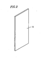
- FIG 1 is a perspective view showing an exemplary secondary battery 100 according to an example of the present invention.
- the secondary battery 100 is a Nickel-metal hydride battery, for example.
- a plurality of the secondary batteries 100 are combined to be used as a power source of a motor in an electric vehicle.
- the secondary battery comprises a battery case 10 .
- the battery case 10 contains pole plates and an electrolyte.
- the battery case 10 has a thin rectangular-parallelepiped shaped battery case body 11 having an open top and a strip-like cover 13 for covering the open top of the battery case body 11.
- the battery case 10 is integrally formed of a synthetic resin.
- a thickness D1 of the battery case 10 is twice as large as the thickness D2 of the conventional thin rectangular-parallelepiped shaped secondary battery shown in Figure 13 so as to increase a power output of the secondary battery 100 while maintaining a low temperature.
- a height H and a width W of the battery case 10 are approximately equal to the height H and the width W of the conventional battery case 50 shown in Figure 13. The height H is greater than the thickness D1 and the width W is greater than the height H.
- An inner space of the battery case body 11 is divided into, for example, six reaction chambers by five walls extending in the thickness D1 direction, equally spaced in the width W direction.
- Each of the reaction chambers contains a plurality of positive plates and a plurality of negative plates which extend in the width W direction of the battery case 10.
- the positive plates and the negative plates are provided, being insulated from each other by separators. All the positive plates in the reaction chamber are connected to a positive pole collector plate extending in the thickness D1 direction. All the negative plates in the reaction chamber are connected to a negative pole collector plate extending in the thickness D1 direction. The positive pole collector plate and the negative pole collector plate oppose to each other within the reactive chamber with all the positive plates and the negative plates interposed therebetween. All the positive plates and the negative plates, and the collector plates are in contact with an electrolyte in the reaction chamber.
- a terminal 20a of the positive pole is provided on a side surface 11x of the battery case body 11 .
- This terminal 20a is serially connected to the positive pole collector plate positioned in the reaction chamber adjacent to the surface 11x.
- a terminal 20b of the negative pole is provided on another side surface 11y of the battery case body 11.
- This terminal 20b is serially connected to the negative pole collector plate positioned in the reaction chamber adjacent to the surface 11y.
- the positive pole collector plates and the negative pole collector plates in the reaction chambers are serially connected to each other except for the reaction chambers located on both ends (in thewidth Wdirection) of the battery case 10 , whose collector plates are connected to the terminals 20a and 20b, respectively.
- ribs 14 extending in the height H direction are provided so as to correspond to walls provided inside the battery case body 11.
- the ribs 14 extending in the height H direction are also provided on edge areas of the side surfaces 11b, which are close to the side surfaces 11x and 11y, in the battery case body 11.
- a radiator 12 as shown in Figure 2 is provided between a pair of the ribs 14 located adjacent to each other.
- the radiators 12 are formed of a metal plate such as aluminum or stainless steel, which has a high heat conductivity, and formed into a rectangular shape in a corresponding size on an inner surface along width W direction in a reaction chamber provided in the battery case body 11 . An entire surface of the radiator 12 is flat.
- the radiators 12 are buried into surfaces 11b of the battery case body 11 so as to oppose the reaction chambers by using, for example, insert molding.
- the cover 13 provided on top of the battery case body 11 is formed of a synthetic resin similar to that used for the battery case body 11 so as to be in a strip form and integrally attached to an upper portion of the battery case body 11.
- the cover 13 comprises a gas emitting outlet 13a for venting internal gas to the outside when the inner pressure in the reactive chamber rises to a predetermined value or above.
- a plurality of the secondary batteries 100 having the above-described structure are stacked side-by-side in the thickness D1 direction of the battery case 10 and the stacked secondary batteries are connected in series or in parallel to each other to form a battery pack.
- the secondary batteries are stacked side-by-side so that the ribs 14 provided on one secondary battery are in contact with those provided on an opposing secondary battery.
- Figure 3 is a cross-sectional view showing a portion of the combined secondary batteries. As shown in Figure 3, spaces 40 are formed between the stacked secondary batteries 100, and between a pair of the ribs 14 contacting each other and an adjacent pair of the ribs 14 contacting each other.
- cooling air for cooling the secondary batteries 100 is provided toward the lower portion of the secondary battery 100.
- the cooling air provided toward the lower portion of the secondary battery 100 passes through the spaces 40 between a pair of stacked secondary batteries 100 from the bottom to the top (i.e., in relation to Figure 1 ).
- the secondary batteries 100 located on both sides of the spaces 40 are cooled by the cooling air.
- the radiators 12 attached to the surfaces 11b of the battery cases 10 of the secondary batteries 100 are in contact with the spaces 40 through which the cooling air passes. Therefore, the cooling air which flows through the spaces 40 efficiently cools down the radiators 12, and thus the surfaces 11b of the battery cases 10 of the secondary batteries 100 to which the radiators 12 are attached can be efficiently cooled.
- the secondary battery 100 shown in Figure 1 has a relatively large thickness D1 of the battery case 10 and the number of positive plates and the negative plates contained in the reaction chambers of the battery case 10 is relatively increased with respect to the conventional secondary batteries.
- the current for charging and/or discharging the battery increases and temperature rise in the reaction chamber is promoted.
- the radiators 12 are provided on the surfaces 11b of the battery case 10 so as to correspond to the reaction chambers, the radiators 12 are efficiently cooled by the cooling air passing through the spaces 40.
- the surfaces 11b of the battery case 10 are efficiently cooled.
- the cooling of the reaction chambers is promoted. As a result, the temperature rise in the reaction chamber is suppressed.
- the secondary battery 100 according to the present invention ensures suppression of the temperature rise in the reaction chamber even if the thickness D1 is increased and the temperature rise in the reaction chambers is promoted. Therefore, the secondary battery 100 according to the present invention can be used in a stable manner for a long time.
- the surfaces 11b of the battery case body 11 of the battery case 10 which is made of a synthetic resin are covered with the radiators 12 which are made of metal.
- moisture or hydrogen gas in the reaction chambers is prevented from permeating the surfaces 11b of the battery case body 11 made of a synthetic resin and leaking out of the reaction chambers. Therefore, the secondary battery 100 according to the present invention can be used in an increased stable manner for a long time.
- the radiators 12 provided so as to correspond to the reaction chambers extend in the height H direction which is a direction for passing through the cooling air.
- a temperature at the upper portion may be higher than the temperature at the lower portion due to the temperature rise.
- the cooling air passes from the bottom to the top of the secondary battery and the radiators 12 having a high heat conductivity radiate heat in a uniform manner, the temperatures in the reaction chambers can be uniformalized throughout the reaction chambers.
- the radiators 12 are not provided for each of the reaction chambers, and the cooling air is not provided, the battery case 10 has maximum temperature of 50°C at the upper portion and 40°C at the lower portion. However, by providing the radiators 12 and passing the cooling air from the bottom to the top, the maximum temperature is uniformalized to about 45°C throughout the whole battery case 10.
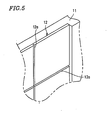
- FIG 4 is a perspective view showing another example of the radiator 12.
- Figure 5 is an enlarged view of a portion indicated by A in Figure 4.
- the radiators 12 are formed of a metal plate, such as aluminum, which has a high conductivity, and formed into a rectangle shape of a predetermined size.
- grooves 12a having V-shape cross sections are provided along the height H direction and the width W direction with a certain space therebetween.
- the cross sections of grooves 12a are not limited to V-shape.
- the cross sections of grooves 12a can be U-shape, or another similar shape.
- the radiators 12 having the above-described structure are attached to the surfaces 11b of the battery case body 11 of the battery case 10 of the secondary battery 100 so as to correspond to the respective reaction chambers. Therefore, the battery case 10 can be efficiently cooled by the radiators 12 attached to the surfaces 11b and can be used in a stable manner for a long time.
- the battery case 10 may bend in the width W direction, for example.
- a plurality of the radiators 12 are located in parallel along the width W direction.
- Each radiator 12 has the grooves 12a extending in the width W direction or the height H direction. Therefore, the radiators 12 bends so as to conform to the bend in the battery case body 11. Therefore, the radiators 12 are not peeled off from the surfaces 11b of the battery case body 11 and the radiators 12 are not damaged.
- the radiators 12 comprise the grooves 12a extending in the width W direction, the radiators 12 bend so as to conform the bend along the height H direction of the battery case body 11. Therefore, the radiators 12 is not be peeled off from the surfaces 11b of the battery case body 11 and the radiators 12 may not be damaged.
- FIG 6 is a perspective view showing another example of the radiator 12.
- Figure 7 is an enlarged view of a portion indicated by B in Figure 6.
- the radiators 12 are formed of a number of radiation pieces 12b formed of a metal plate such as aluminum, which has a high heat conductivity.
- the radiation pieces 12b are provided in a grid pattern along the height H direction and the width Wdirection, with slits 12c therebetween, and buried into the surfaces 11b .
- the radiators 12 are formed of a number of the radiation pieces 12b separated from each other, the radiators 12 further conforms to the bend of the battery case body 11 . Since the radiators 12 are separated from each other, even if the battery case body 11 bends, the radiators 12 are not damaged.
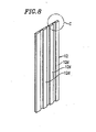
- FIG 8 is a perspective view showing yet another example of the radiator 12.
- Figure 9 is an enlarged view of a portion indicated by C in Figure 8.
- the radiators 12 are formed of a metal plate, such as aluminum, which has a high heat conductivity.
- a plurality of convex stripes 12d extending in the height H direction are provided with an equal space therebetween in the width W direction.
- the convex stripes 12d are formed by cutting grooves having constant widths along the height H direction in a surface of a metal plate.
- the convex stripes 12d are not protruded from the surfaces 11b of the battery case body 11.
- the convex stripes 12d are located in the spaces 40 formed by stacking a pair of the secondary batteries 100 side-by-side. Therefore, the surface area of the radiators 12 to be in contact with the cooling air flowing through the spaces 40 increases and the radiators 12 are efficiently cooled.
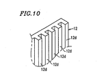
- FIG 10 is a perspective view showing yet another example of the radiator 12. Similar to the radiators 12 shown in Figures 8 and 9, the radiators 12 shown in Figure 10 are formed of a metal plate, such as aluminum, which has a high heat conductivity. A plurality of the convex stripes 12d extending along the height H direction are formed with equal spaces therebetween in the width W direction. The convex stripes 12d are formed so that, when the radiators 12 are buried into areas corresponding to the reaction chambers on the surfaces 11b of the battery case body 11, the convex stripes 12d protrude from the surfaces 11b of the battery case body 11 and align with a surface of the ribs 14 provided on the surfaces 11b. The interval between the convex stripes 12d shown in Figure 10 is smaller than the interval between the convex stripes 12d provided on the radiators 12 shown in Figures 8 and 9.
- the secondary batteries 100 which comprise the radiators 12 having the above-described structure are stacked side-by-side, the ribs 14 provided on one secondary battery are in contact with those provided on an opposing secondary battery.
- the convex stripes 12d of one secondary battery are also in contact with those of an opposing secondary battery.
- the spaces 40 for passing through the cooling air are formed between a pair of the convex stripes 12d contacting each other and an adjacent pair of the convex stripes 12d contacting each other.
- the radiators 12 By passing the cooling air through the spaces 40, the radiators 12 are cooled. Since the convex stripes 12d are provided in the radiators 12 shown in Figure 11, the surface area to be in contact with cooling air increases and the radiators 12 are efficiently cooled.
- the cooling air passes through the spaces having the small cross sections defined by the convex stripes 12d provided on the radiators 12 , the flow velocity of the cooling air increases, thereby further efficiently cooling the radiators 12.
- the structure of the convex stripes 12d formed on the radiators 12 is not limited to the structure in which a pair of the convex stripes 12d are in contact with each other when the secondary batteries 100 are stacked side-by-side. Instead, as shown in Figure 12, the convex stripes 12d may be protruded further to contact the middle portion between two adjacent convex stripes 12d of the opposite radiators 12 rather than the convex stripes 12d of each of,the radiators 12 contacting each other.
- the spaces 40 are formed by the convex stripes 12d interdigitated with each other, which are provided on each of the radiators 12 contacting each other.
- the radiators 12 are cooled. Since the convex stripes 12d are provided in the radiators 12 shown in Figure 12, the surface area to be in contact with cooling air flowing through the spaces 40 increases and the radiators 12 are efficiently cooled.
- the cooling air passes through the spaces having the small cross sections defined by the convex stripes 12d provided on the radiators 12 , the flow velocity of the cooling air increases, thereby further efficiently cooling the radiators 12.
- radiators are provided so as to correspond to the respective reaction chambers provided inside the battery case, and thus the reaction chambers are efficiently cooled.
- the thickness of the battery case is increased due to an increase in the number of the pole plates in the reaction chamber, the temperature rise within the chamber can be suppressed.
Description
- The present invention relates to a secondary battery used in an electric vehicle or the like. Specifically, the present invention relates to a thin rectangular-parallelepiped shaped secondary battery having an improved cooling efficiency.
- A secondary battery which can be repeatedly charged and discharged is used as a power source of a motor in various types of electric vehicles, for example, a hybrid electric vehicle or the like. A secondary battery, when used in an electric vehicle, is required to have a large capacity of electricity and a high voltage. Therefore, a plurality of secondary batteries are combined to form a battery pack and the battery pack is mounted in a vehicle.
- Figure 13 is a perspective view showing an exemplary
secondary battery 200 which forms a battery pack to be mounted in an electric vehicle. Thesecondary battery 200 has a battery case 50. The battery case 50 has a battery case body 51 formed into a thin rectangular-parallelepiped shape having an open top and a strip-like cover 53 for covering the open top of the battery case body 51. - The thin rectangular-parallelepiped shaped battery case 50 has a small thickness D2, a height H greater than the thickness D2, and a width W greater than the height H.
- An inner space of the battery case body 51 is divided into, for example, six reaction chambers by five walls extending in the thickness D2 direction, equally spaced in the width W direction. Each of the reaction chambers contains a plurality of positive plates and a plurality of negative plates which extend in the width W direction of the battery case 50.
- In each reaction chamber, the positive plates and the negative plates are provided, being insulated from each other by separators. All the positive plates in the reaction chamber are connected to a positive pole collector plate extending in the thickness D2 direction. All the negative plates in the reaction chamber are connected to a negative pole collector plate extending in the thickness D2 direction. The positive pole collector plate and the negative pole collector plate oppose each other within the reactive chamber with all the positive plates and the negative plates interposed therebetween. All the positive plates and the negative plates, and the collector plates are in contact with an electrolyte in the reaction chamber.
- On a
side surface 51x of the battery case body 51, aterminal 55a of the positive pole is provided. Thisterminal 55a is serially connected to the positive pole collector plate positioned in the reaction chamber adjacent to thesurface 51x. On anotherside surface 51y of the battery case body 51, aterminal 55b of the negative pole is provided. Thisterminal 55b is serially connected to the collector plate of the negative pole positioned in the reaction chamber adjacent to thesurface 51y. The positive pole collector plate and the negative pole collector plate are serially connected to the respective positive pole collector plate and the negative pole collector plate in an adjacent reaction chamber. - A plurality of the
secondary batteries 200 having the above-described structure are stacked side-by-side in the thickness D2 direction and connected in series or in parallel to each other to form a battery pack. The battery pack is mounted in an electric vehicle. - The
secondary battery 200 has a problem that, due to a reaction resistance caused by a battery reaction and component resistance caused by collecting electricity and connection between the components, a temperature in the reaction chamber rises and thus a temperature of the battery case 50 rises. Especially, when a large amount of current is charged and/or discharged, temperature of the battery case 50 rises significantly. If the temperature in the reaction chamber rises, battery reaction in the reaction chamber is weakened. Thus, cooling air is supplied and passed through the space between a pair of stacked secondary batteries in the height H direction (e.g., from the bottom to the top of the battery case 50 in Figure 13) to cool the battery case 50 of the secondary battery. - A
secondary battery 200 hasribs 54 which extend in the height H direction on eachsurface 51b along the width W direction of the battery case body 51 with a certain space therebetween in the width W direction for smoothly passing the cooling air through the spaces between the pair of the stacked secondary batteries. By keeping theribs 54 of one secondary battery in contact with those of an adjacent secondary battery in a structure in which thebatteries 200 are stacked side-by-side, spaces for passing the cooling air are formed between thesurfaces 51b of thesecondary batteries 200. Thesecondary battery 200 is cooled by passing the cooling air through these spaces. - A number of
protrusions 51c are provided on thesurfaces 51b of the battery case body 51 to improve a resistance of thesecondary battery 200 against pressure. - In recent years, for improving a power output of such a thin rectangular-parallelepiped shaped
secondary battery 200 at a low temperature, the capacity of thesecondary battery 200 is increased by increasing only the thickness D2 of the battery case 50 to increase the number of the plates contained in each reaction chamber. - However, such an attempt to increase the capacity causes a problem that the temperature in the each reaction chamber is further raised by the heat of reaction. As described above, in such a
secondary battery 200, each reaction chamber is cooled by passing the cooling air along thesurfaces 51b of the battery case 51. If only the thickness D2 of the battery case 51 of thesecondary battery 200 is increased, an area for radiating heat due to cooling air does not increase. Thus, each chamber cannot be sufficiently cooled. - EP-A-1 117 138 discloses a battery comprising a battery case formed into a thin rectangular-parallelepiped shape, and whose inner space is divided into a plurality of reaction chambers by walls extending in the thickness direction formed with an appropriate space therebetween in a width direction. One radiator is provided on an entire external surface of the battery case.
- US-A-5 492 779 discloses a battery having outwardly projecting external ribs extending in a direction perpendicular to the width of the battery.
- EP-A-0 881 693 and FR-A-2 742 002 disclose a battery having an external surface comprising vertical protruding parts and a plate covering the entire surface of the external surface of the battery, wherein the space, formed between the external surface of the battery and the plate due to the protruding parts, is provided to allow a cooling fluid to circulate on the external surface of the battery to cool the battery.
- JP-A-01 014616 discloses a battery pack including a plurality of batteries spaced by a spacer to allow air to circulate into the space between the battery to cool the battery.
- According to one aspect of the present invention, there is provided a secondary battery comprising : a battery case formed of a synthetic resin and formed into a thin rectangular-parallelepiped shape, and whose inner space is divided into a plurality of reaction chambers by walls formed with an appropriate space therebetween in a width direction ; and a plurality of radiators respectively provided on an external surface along the width direction of the battery case so as to correspond to the reaction chambers; and wherein each of said radiators are separated from each other in a width direction.
- In one embodiment of the present invention, each of the radiators is formed of a metal plate which has a high heat conductivity.
- In one embodiment of the present invention, the radiators are integrally formed with the battery case by insert molding.
- In one embodiment of the present invention, a plurality of grooves extending in the width direction of the battery case and a plurality of grooves extending in a height direction are provided on a surface of each radiator.
- In one embodiment of the present invention, each of the radiators is formed of a plurality of radiation pieces located along the width direction of the battery case and the height direction.
- In one embodiment of the present invention, each of the radiators comprises a plurality of convex stripes extending in the height direction of the battery case.
- In one embodiment of the present invention, the convex stripes of each of the radiators protrude from the surface along the width direction of the battery case.
- Thus, the invention described herein makes possible the advantages of providing a secondary battery in which it is capable to cool a battery case even if a thickness of the battery case is increased.
- These and other advantages of the present invention will become apparent to those skilled in the art upon reading and understanding the following detailed description with reference to the accompanying figures.
-
- Figure 1 is a perspective view showing an example of a secondary battery according to the present invention.
- Figure 2 is a perspective view showing a radiator used in the secondary battery of Figure 1.
- Figure 3 is a cross-sectional view showing a portion of the combined secondary batteries of Figure 1.
- Figure 4 is a perspective view showing another radiator used in the secondary battery according to the present invention.
- Figure 5 is an enlarged view of the portion indicated by A in Figure 4.
- Figure 6 is a perspective view showing another example of the radiator used in the secondary battery according to the present invention.
- Figure 7 is an enlarged view of the portion indicated by B in Figure 6.
- Figure 8 is a perspective view showing yet another radiator used in the secondary battery according to the present invention.
- Figure 9 is an enlarged view of the portion indicated by C in Figure 8.
- Figure 10 is a perspective view showing a portion of yet another radiator used in the secondary battery according to the present invention.
- Figure 11 is a cross-sectional view of an essential portion of the combined secondary batteries used in the secondary battery according to the present invention.
- Figure 12 is a cross-sectional view of an essential portion of the combined secondary batteries used in the secondary battery according to the present invention.
- Figure 13 is a perspective view showing an example of a conventional secondary battery.
- Hereinafter, examples of the present invention will be described with reference to the drawings.
- Figure 1 is a perspective view showing an exemplary
secondary battery 100 according to an example of the present invention. Thesecondary battery 100 is a Nickel-metal hydride battery, for example. A plurality of thesecondary batteries 100 are combined to be used as a power source of a motor in an electric vehicle. As shown in Figure 1, the secondary battery comprises abattery case 10. Thebattery case 10 contains pole plates and an electrolyte. Thebattery case 10 has a thin rectangular-parallelepiped shapedbattery case body 11 having an open top and a strip-like cover 13 for covering the open top of thebattery case body 11. - The
battery case 10 is integrally formed of a synthetic resin. A thickness D1 of thebattery case 10 is twice as large as the thickness D2 of the conventional thin rectangular-parallelepiped shaped secondary battery shown in Figure 13 so as to increase a power output of thesecondary battery 100 while maintaining a low temperature. A height H and a width W of thebattery case 10 are approximately equal to the height H and the width W of the conventional battery case 50 shown in Figure 13. The height H is greater than the thickness D1 and the width W is greater than the height H. - An inner space of the
battery case body 11 is divided into, for example, six reaction chambers by five walls extending in the thickness D1 direction, equally spaced in the width W direction. Each of the reaction chambers contains a plurality of positive plates and a plurality of negative plates which extend in the width W direction of thebattery case 10. - In each reaction chamber, the positive plates and the negative plates are provided, being insulated from each other by separators. All the positive plates in the reaction chamber are connected to a positive pole collector plate extending in the thickness D1 direction. All the negative plates in the reaction chamber are connected to a negative pole collector plate extending in the thickness D1 direction. The positive pole collector plate and the negative pole collector plate oppose to each other within the reactive chamber with all the positive plates and the negative plates interposed therebetween. All the positive plates and the negative plates, and the collector plates are in contact with an electrolyte in the reaction chamber.
- On a side surface 11x of the
battery case body 11, a terminal 20a of the positive pole is provided. This terminal 20a is serially connected to the positive pole collector plate positioned in the reaction chamber adjacent to the surface 11x. On anotherside surface 11y of thebattery case body 11, a terminal 20b of the negative pole is provided. This terminal 20b is serially connected to the negative pole collector plate positioned in the reaction chamber adjacent to thesurface 11y. The positive pole collector plates and the negative pole collector plates in the reaction chambers are serially connected to each other except for the reaction chambers located on both ends (in thewidth Wdirection) of thebattery case 10, whose collector plates are connected to theterminals 20a and 20b, respectively. - On a side surface(s) 11b of the
battery case body 11 along the width W direction,ribs 14 extending in the height H direction (e.g., from the bottom to the top of thebattery case 10 in Figure 1) are provided so as to correspond to walls provided inside thebattery case body 11. Theribs 14 extending in the height H direction are also provided on edge areas of the side surfaces 11b, which are close to the side surfaces 11x and 11y, in thebattery case body 11. Between a pair of theribs 14 located adjacent to each other, aradiator 12 as shown in Figure 2 is provided. - The
radiators 12 are formed of a metal plate such as aluminum or stainless steel, which has a high heat conductivity, and formed into a rectangular shape in a corresponding size on an inner surface along width W direction in a reaction chamber provided in thebattery case body 11. An entire surface of theradiator 12 is flat. - The
radiators 12 are buried intosurfaces 11b of thebattery case body 11 so as to oppose the reaction chambers by using, for example, insert molding. - The
cover 13 provided on top of thebattery case body 11 is formed of a synthetic resin similar to that used for thebattery case body 11 so as to be in a strip form and integrally attached to an upper portion of thebattery case body 11. Thecover 13 comprises agas emitting outlet 13a for venting internal gas to the outside when the inner pressure in the reactive chamber rises to a predetermined value or above. - A plurality of the
secondary batteries 100 having the above-described structure are stacked side-by-side in the thickness D1 direction of thebattery case 10 and the stacked secondary batteries are connected in series or in parallel to each other to form a battery pack. In such a structure, the secondary batteries are stacked side-by-side so that theribs 14 provided on one secondary battery are in contact with those provided on an opposing secondary battery. Figure 3 is a cross-sectional view showing a portion of the combined secondary batteries. As shown in Figure 3,spaces 40 are formed between the stackedsecondary batteries 100, and between a pair of theribs 14 contacting each other and an adjacent pair of theribs 14 contacting each other. - In the battery pack comprising a number of
secondary batteries 100 combined with each other, cooling air for cooling thesecondary batteries 100 is provided toward the lower portion of thesecondary battery 100. The cooling air provided toward the lower portion of thesecondary battery 100 passes through thespaces 40 between a pair of stackedsecondary batteries 100 from the bottom to the top (i.e., in relation to Figure 1). Thus, thesecondary batteries 100 located on both sides of thespaces 40 are cooled by the cooling air. - The
radiators 12 attached to thesurfaces 11b of thebattery cases 10 of thesecondary batteries 100 are in contact with thespaces 40 through which the cooling air passes. Therefore, the cooling air which flows through thespaces 40 efficiently cools down theradiators 12, and thus thesurfaces 11b of thebattery cases 10 of thesecondary batteries 100 to which theradiators 12 are attached can be efficiently cooled. - The
secondary battery 100 shown in Figure 1 has a relatively large thickness D1 of thebattery case 10 and the number of positive plates and the negative plates contained in the reaction chambers of thebattery case 10 is relatively increased with respect to the conventional secondary batteries. Thus, the current for charging and/or discharging the battery increases and temperature rise in the reaction chamber is promoted. However, since theradiators 12 are provided on thesurfaces 11b of thebattery case 10 so as to correspond to the reaction chambers, theradiators 12 are efficiently cooled by the cooling air passing through thespaces 40. Thus, thesurfaces 11b of thebattery case 10 are efficiently cooled. The cooling of the reaction chambers is promoted. As a result, the temperature rise in the reaction chamber is suppressed. - As described above, the
secondary battery 100 according to the present invention ensures suppression of the temperature rise in the reaction chamber even if the thickness D1 is increased and the temperature rise in the reaction chambers is promoted. Therefore, thesecondary battery 100 according to the present invention can be used in a stable manner for a long time. - The
surfaces 11b of thebattery case body 11 of thebattery case 10 which is made of a synthetic resin are covered with theradiators 12 which are made of metal. Thus, moisture or hydrogen gas in the reaction chambers is prevented from permeating thesurfaces 11b of thebattery case body 11 made of a synthetic resin and leaking out of the reaction chambers. Therefore, thesecondary battery 100 according to the present invention can be used in an increased stable manner for a long time. - The
radiators 12 provided so as to correspond to the reaction chambers extend in the height H direction which is a direction for passing through the cooling air. In the reaction chambers, for example, a temperature at the upper portion may be higher than the temperature at the lower portion due to the temperature rise. However, since the cooling air passes from the bottom to the top of the secondary battery and theradiators 12 having a high heat conductivity radiate heat in a uniform manner, the temperatures in the reaction chambers can be uniformalized throughout the reaction chambers. When theradiators 12 are not provided for each of the reaction chambers, and the cooling air is not provided, thebattery case 10 has maximum temperature of 50°C at the upper portion and 40°C at the lower portion. However, by providing theradiators 12 and passing the cooling air from the bottom to the top, the maximum temperature is uniformalized to about 45°C throughout thewhole battery case 10. - Figure 4 is a perspective view showing another example of the
radiator 12. Figure 5 is an enlarged view of a portion indicated by A in Figure 4. As described above, theradiators 12 are formed of a metal plate, such as aluminum, which has a high conductivity, and formed into a rectangle shape of a predetermined size. On both side surfaces,grooves 12a having V-shape cross sections are provided along the height H direction and the width W direction with a certain space therebetween. The cross sections ofgrooves 12a are not limited to V-shape. The cross sections ofgrooves 12a can be U-shape, or another similar shape. - The
radiators 12 having the above-described structure are attached to thesurfaces 11b of thebattery case body 11 of thebattery case 10 of thesecondary battery 100 so as to correspond to the respective reaction chambers. Therefore, thebattery case 10 can be efficiently cooled by theradiators 12 attached to thesurfaces 11b and can be used in a stable manner for a long time. - If the pressure in the reaction chambers increases due to an electrochemical reaction occurs in the reaction chamber, the
battery case 10 may bend in the width W direction, for example. In thebattery case 10, on thesurfaces 11b of thebattery case body 11, a plurality of theradiators 12 are located in parallel along the width W direction. Eachradiator 12 has thegrooves 12a extending in the width W direction or the height H direction. Therefore, theradiators 12 bends so as to conform to the bend in thebattery case body 11. Therefore, theradiators 12 are not peeled off from thesurfaces 11b of thebattery case body 11 and theradiators 12 are not damaged. - Even when the
battery case body 11 of thebattery case 10 bends along the height H direction, since theradiators 12 comprise thegrooves 12a extending in the width W direction, theradiators 12 bend so as to conform the bend along the height H direction of thebattery case body 11. Therefore, theradiators 12 is not be peeled off from thesurfaces 11b of thebattery case body 11 and theradiators 12 may not be damaged. - Figure 6 is a perspective view showing another example of the
radiator 12. Figure 7 is an enlarged view of a portion indicated by B in Figure 6. Theradiators 12 are formed of a number ofradiation pieces 12b formed of a metal plate such as aluminum, which has a high heat conductivity. On areas corresponding to the respective reaction chambers on thesurfaces 11b of thebattery case body 11, theradiation pieces 12b are provided in a grid pattern along the height H direction and the width Wdirection, withslits 12c therebetween, and buried into thesurfaces 11b. - Thus, since the
radiators 12 are formed of a number of theradiation pieces 12b separated from each other, theradiators 12 further conforms to the bend of thebattery case body 11. Since theradiators 12 are separated from each other, even if thebattery case body 11 bends, theradiators 12 are not damaged. - Figure 8 is a perspective view showing yet another example of the
radiator 12. Figure 9 is an enlarged view of a portion indicated by C in Figure 8. Theradiators 12 are formed of a metal plate, such as aluminum, which has a high heat conductivity. On a surface which is in contact with thespaces 40 when thesecondary batteries 100 are stacked side-by-side, a plurality ofconvex stripes 12d extending in the height H direction are provided with an equal space therebetween in the width W direction. For example, theconvex stripes 12d are formed by cutting grooves having constant widths along the height H direction in a surface of a metal plate. In thebattery case body 11 having such a structure, since theradiators 12 are buried into thesurfaces 11b of thebattery case body 11, theconvex stripes 12d are not protruded from thesurfaces 11b of thebattery case body 11. - In the
radiators 12 having the above-described structure, theconvex stripes 12d are located in thespaces 40 formed by stacking a pair of thesecondary batteries 100 side-by-side. Therefore, the surface area of theradiators 12 to be in contact with the cooling air flowing through thespaces 40 increases and theradiators 12 are efficiently cooled. - Figure 10 is a perspective view showing yet another example of the
radiator 12. Similar to theradiators 12 shown in Figures 8 and 9, theradiators 12 shown in Figure 10 are formed of a metal plate, such as aluminum, which has a high heat conductivity. A plurality of theconvex stripes 12d extending along the height H direction are formed with equal spaces therebetween in the width W direction. Theconvex stripes 12d are formed so that, when theradiators 12 are buried into areas corresponding to the reaction chambers on thesurfaces 11b of thebattery case body 11, theconvex stripes 12d protrude from thesurfaces 11b of thebattery case body 11 and align with a surface of theribs 14 provided on thesurfaces 11b. The interval between theconvex stripes 12d shown in Figure 10 is smaller than the interval between theconvex stripes 12d provided on theradiators 12 shown in Figures 8 and 9. - As shown in Figure 11, when the
secondary batteries 100 which comprise theradiators 12 having the above-described structure are stacked side-by-side, theribs 14 provided on one secondary battery are in contact with those provided on an opposing secondary battery. Theconvex stripes 12d of one secondary battery are also in contact with those of an opposing secondary battery. Thus, thespaces 40 for passing through the cooling air are formed between a pair of theconvex stripes 12d contacting each other and an adjacent pair of theconvex stripes 12d contacting each other. - By passing the cooling air through the
spaces 40, theradiators 12 are cooled. Since theconvex stripes 12d are provided in theradiators 12 shown in Figure 11, the surface area to be in contact with cooling air increases and theradiators 12 are efficiently cooled. - Moreover, since the cooling air passes through the spaces having the small cross sections defined by the
convex stripes 12d provided on theradiators 12, the flow velocity of the cooling air increases, thereby further efficiently cooling theradiators 12. - The structure of the
convex stripes 12d formed on theradiators 12 is not limited to the structure in which a pair of theconvex stripes 12d are in contact with each other when thesecondary batteries 100 are stacked side-by-side. Instead, as shown in Figure 12, theconvex stripes 12d may be protruded further to contact the middle portion between two adjacentconvex stripes 12d of theopposite radiators 12 rather than theconvex stripes 12d of each of,theradiators 12 contacting each other. - As described above, the
spaces 40 are formed by theconvex stripes 12d interdigitated with each other, which are provided on each of theradiators 12 contacting each other. By passing the cooling air through thespaces 40, theradiators 12 are cooled. Since theconvex stripes 12d are provided in theradiators 12 shown in Figure 12, the surface area to be in contact with cooling air flowing through thespaces 40 increases and theradiators 12 are efficiently cooled. - Moreover, since the cooling air passes through the spaces having the small cross sections defined by the
convex stripes 12d provided on theradiators 12, the flow velocity of the cooling air increases, thereby further efficiently cooling theradiators 12. - According to the present invention, on the surface of the battery case of the secondary battery, which is formed of a synthetic resin and formed into a thin rectangular-parallelepiped shape, radiators are provided so as to correspond to the respective reaction chambers provided inside the battery case, and thus the reaction chambers are efficiently cooled. As a result, even when the thickness of the battery case is increased due to an increase in the number of the pole plates in the reaction chamber, the temperature rise within the chamber can be suppressed.
- Various other modifications will be apparent to and can be readily made by those skilled in the art without departing from the scope of this invention. Accordingly, it is not intended that the scope of the claims appended hereto be limited to the description as set forth herein, but rather that the claims be broadly construed.
Claims (7)
- A secondary battery comprising:a battery case formed of a synthetic resin and formed into a thin rectangular-parallelepiped shape, and whose inner space is divided into a plurality of reaction chambers by walls formed with an appropriate space therebetween in a width direction; anda plurality of radiators respectively provided on an external surface along the width direction of the battery case so as to correspond to the reaction chambers; andwherein each of said radiators are separated from each other in a width direction.
- A secondary battery according to claim 1, wherein each of the radiators is formed of a metal plate which has a high heat conductivity.
- A secondary battery according to claim 1, wherein the radiators are integrally formed with the battery case by insert molding.
- A secondary battery according to claim 1, wherein a plurality of grooves extending in the width direction of the battery case and a plurality of grooves extending in a height direction are provided on a surface of each radiator.
- A secondary battery according to claim 1, wherein each of the radiators is formed of a plurality of radiation pieces located along the width direction of the battery case and the height direction.
- A secondary battery according to claim 1, wherein each of the radiators comprises a plurality of convex stripes extending in the height direction of the battery case.
- A secondary battery according to claim 6, wherein the convex stripes of each of the radiators protrude from the surface along the width direction of the battery case.
Applications Claiming Priority (2)
| Application Number | Priority Date | Filing Date | Title |
|---|---|---|---|
| JP2001200855 | 2001-07-02 | ||
| JP2001200855A JP4303430B2 (en) | 2001-07-02 | 2001-07-02 | Secondary battery and battery pack |
Publications (2)
| Publication Number | Publication Date |
|---|---|
| EP1278251A1 EP1278251A1 (en) | 2003-01-22 |
| EP1278251B1 true EP1278251B1 (en) | 2006-06-21 |
Family
ID=19037909
Family Applications (1)
| Application Number | Title | Priority Date | Filing Date |
|---|---|---|---|
| EP20020014060 Expired - Lifetime EP1278251B1 (en) | 2001-07-02 | 2002-07-01 | Cooling arrangement on Case of Secondary Battery |
Country Status (4)
| Country | Link |
|---|---|
| US (1) | US20030003351A1 (en) |
| EP (1) | EP1278251B1 (en) |
| JP (1) | JP4303430B2 (en) |
| DE (1) | DE60212504T2 (en) |
Families Citing this family (11)
| Publication number | Priority date | Publication date | Assignee | Title |
|---|---|---|---|---|
| JP3850688B2 (en) * | 2001-07-19 | 2006-11-29 | 松下電器産業株式会社 | Cooling device for prismatic battery and battery pack |
| US20060183017A1 (en) * | 2003-03-31 | 2006-08-17 | Takeshi Kanai | Radiating member for laminated battery and method of manufacturing the same |
| JP4830302B2 (en) * | 2005-01-25 | 2011-12-07 | トヨタ自動車株式会社 | Secondary battery |
| KR100612239B1 (en) * | 2005-04-26 | 2006-08-11 | 삼성에스디아이 주식회사 | Secondary battery module and wall of secondary battery |
| US20080280198A1 (en) * | 2007-05-07 | 2008-11-13 | Ajith Kuttannair Kumar | Battery mechanical packaging |
| DE102008015622B4 (en) * | 2008-03-26 | 2010-03-25 | Iq Power Licensing Ag | Liquid electrolyte battery with tempering device and temperature compensation |
| CN102317097B (en) * | 2009-02-24 | 2015-12-02 | 日产自动车株式会社 | Battery installation structure |
| WO2010098270A1 (en) | 2009-02-24 | 2010-09-02 | 日産自動車株式会社 | Battery installation structure |
| CN103022389B (en) * | 2011-09-22 | 2017-09-12 | 深圳市沃特玛电池有限公司 | Battery case |
| KR101544548B1 (en) * | 2013-10-24 | 2015-08-13 | 엘지전자 주식회사 | Cell Module Assembly |
| US10306442B1 (en) * | 2018-01-16 | 2019-05-28 | Skylo Technologies Inc. | Devices and methods for specialized machine-to-machine communication transmission network modes via edge node capabilities |
Family Cites Families (17)
| Publication number | Priority date | Publication date | Assignee | Title |
|---|---|---|---|---|
| US4020244A (en) * | 1975-02-18 | 1977-04-26 | Motorola, Inc. | Clamping structure for battery cells |
| JPS5661766A (en) * | 1979-10-24 | 1981-05-27 | Japan Storage Battery Co Ltd | Pasted lead acid battery |
| JPH0714616A (en) * | 1993-06-23 | 1995-01-17 | Japan Storage Battery Co Ltd | Storage battery pack |
| US5879831A (en) * | 1993-10-25 | 1999-03-09 | Ovonic Battery Company, Inc. | Mechanical and thermal improvements in metal hydride batteries, battery modules and battery packs |
| US5585204A (en) * | 1993-12-27 | 1996-12-17 | Honda Giken Kogyo Kabushiki Kaisha | Temperature control structure for batteries and battery box for housing such batteries |
| US5492779A (en) * | 1994-10-24 | 1996-02-20 | General Motors Corporation | Heat dissipating battery |
| JP3271494B2 (en) * | 1995-10-24 | 2002-04-02 | 松下電器産業株式会社 | Stacked sealed alkaline storage battery |
| FR2742002B1 (en) * | 1995-11-30 | 1998-02-20 | Peugeot | ELECTRIC ACCUMULATOR BATTERY PROVIDED WITH COOLING MEANS |
| JPH09329395A (en) * | 1996-06-06 | 1997-12-22 | Furukawa Electric Co Ltd:The | Heat sink |
| US5818693A (en) * | 1997-01-09 | 1998-10-06 | Thermal Corp. | Heat dissipating computer case having oriented fibers and heat pipe |
| FR2762932B1 (en) * | 1997-05-02 | 1999-07-23 | Alsthom Cge Alcatel | WATERPROOF ELECTROCHEMICAL GENERATOR |
| US6134783A (en) * | 1997-10-29 | 2000-10-24 | Bargman; Ronald D. | Heat sink and process of manufacture |
| US6255015B1 (en) * | 1998-08-23 | 2001-07-03 | Ovonic Battery Company, Inc. | Monoblock battery assembly |
| IT248760Y1 (en) * | 1999-04-01 | 2003-02-12 | Stocchiero Olimpio | BATTERY CONTAINER WITH INCREASED RIGIDITY WALLS |
| JP4559567B2 (en) * | 1999-10-08 | 2010-10-06 | パナソニック株式会社 | Sealed storage battery |
| JP2001196103A (en) * | 2000-01-12 | 2001-07-19 | Matsushita Electric Ind Co Ltd | Cooling structure of integrated battery |
| JP4921629B2 (en) * | 2000-03-31 | 2012-04-25 | パナソニック株式会社 | Fluid-cooled battery pack system |
-
2001
- 2001-07-02 JP JP2001200855A patent/JP4303430B2/en not_active Expired - Fee Related
-
2002
- 2002-07-01 DE DE2002612504 patent/DE60212504T2/en not_active Expired - Lifetime
- 2002-07-01 EP EP20020014060 patent/EP1278251B1/en not_active Expired - Lifetime
- 2002-07-02 US US10/188,729 patent/US20030003351A1/en not_active Abandoned
Also Published As
| Publication number | Publication date |
|---|---|
| JP4303430B2 (en) | 2009-07-29 |
| DE60212504D1 (en) | 2006-08-03 |
| JP2003017141A (en) | 2003-01-17 |
| DE60212504T2 (en) | 2007-06-21 |
| EP1278251A1 (en) | 2003-01-22 |
| US20030003351A1 (en) | 2003-01-02 |
Similar Documents
| Publication | Publication Date | Title |
|---|---|---|
| EP1278263B1 (en) | Prismatic battery having cooling structure and battery pack using the same | |
| EP1139483B1 (en) | Fluid-cooled battery pack system | |
| US7189474B2 (en) | Battery pack | |
| US9023503B2 (en) | Battery module with cooling structure of high efficiency | |
| KR101095346B1 (en) | Battery Module Having Excellent Heat Dissipation Ability and Battery Pack Employed with the Same | |
| US7858220B2 (en) | Battery array for cooling battery modules with cooling air | |
| US8071234B2 (en) | Battery pack | |
| JP5490241B2 (en) | Battery module including a heat dissipation member having a novel structure and medium- or large-sized battery pack | |
| EP2853436B1 (en) | Battery module including indirect air cooling structure | |
| US8435664B2 (en) | Battery system having temperature equalizing walls in ducts | |
| EP2068381B1 (en) | Battery system | |
| US20070134550A1 (en) | Prismatic sealed rechargeable battery, battery module, and battery pack | |
| EP2509150A2 (en) | Battery module having excellent cooling efficiency and compact structure and middle or large-sized battery pack | |
| EP2479835A2 (en) | Battery module having a temperature sensor installed thereon, and medium or large battery pack including same | |
| JP5518386B2 (en) | Battery system | |
| KR100717751B1 (en) | Secondary battery module | |
| KR102411235B1 (en) | Battery pack with cell suppression | |
| EP1278251B1 (en) | Cooling arrangement on Case of Secondary Battery | |
| CN114631219A (en) | Battery cooling plate for electric vehicle | |
| US9214653B2 (en) | Secondary battery comprising terminal insulating members | |
| JP2018181765A (en) | Battery pack | |
| KR101262033B1 (en) | Cooling Member Having Improved Reliability to Cooling Design and Battery Module Employed with the Same | |
| KR20060086122A (en) | Secondary battery module | |
| KR20200073721A (en) | Battery Pack | |
| KR20220049724A (en) | Battery Pack With Improved Cooling Performance And Device Including It |
Legal Events
| Date | Code | Title | Description |
|---|---|---|---|
| PUAI | Public reference made under article 153(3) epc to a published international application that has entered the european phase |
Free format text: ORIGINAL CODE: 0009012 |
|
| AK | Designated contracting states |
Kind code of ref document: A1 Designated state(s): AT BE BG CH CY CZ DE DK EE ES FI FR GB GR IE IT LI LU MC NL PT SE SK TR |
|
| AX | Request for extension of the european patent |
Free format text: AL;LT;LV;MK;RO;SI |
|
| 17P | Request for examination filed |
Effective date: 20030131 |
|
| 17Q | First examination report despatched |
Effective date: 20030303 |
|
| AKX | Designation fees paid |
Designated state(s): DE FR GB |
|
| GRAP | Despatch of communication of intention to grant a patent |
Free format text: ORIGINAL CODE: EPIDOSNIGR1 |
|
| RTI1 | Title (correction) |
Free format text: COOLING ARRANGEMENT ON CASE OF SECONDARY BATTERY |
|
| GRAS | Grant fee paid |
Free format text: ORIGINAL CODE: EPIDOSNIGR3 |
|
| GRAA | (expected) grant |
Free format text: ORIGINAL CODE: 0009210 |
|
| AK | Designated contracting states |
Kind code of ref document: B1 Designated state(s): DE FR GB |
|
| REG | Reference to a national code |
Ref country code: GB Ref legal event code: FG4D |
|
| REF | Corresponds to: |
Ref document number: 60212504 Country of ref document: DE Date of ref document: 20060803 Kind code of ref document: P |
|
| ET | Fr: translation filed | ||
| PLBE | No opposition filed within time limit |
Free format text: ORIGINAL CODE: 0009261 |
|
| STAA | Information on the status of an ep patent application or granted ep patent |
Free format text: STATUS: NO OPPOSITION FILED WITHIN TIME LIMIT |
|
| 26N | No opposition filed |
Effective date: 20070322 |
|
| REG | Reference to a national code |
Ref country code: DE Ref legal event code: R084 Ref document number: 60212504 Country of ref document: DE |
|
| REG | Reference to a national code |
Ref country code: GB Ref legal event code: 746 Effective date: 20160420 |
|
| REG | Reference to a national code |
Ref country code: FR Ref legal event code: PLFP Year of fee payment: 15 |
|
| REG | Reference to a national code |
Ref country code: FR Ref legal event code: PLFP Year of fee payment: 16 |
|
| REG | Reference to a national code |
Ref country code: FR Ref legal event code: PLFP Year of fee payment: 17 |
|
| REG | Reference to a national code |
Ref country code: DE Ref legal event code: R079 Ref document number: 60212504 Country of ref document: DE Free format text: PREVIOUS MAIN CLASS: H01M0002020000 Ipc: H01M0050100000 |
|
| PGFP | Annual fee paid to national office [announced via postgrant information from national office to epo] |
Ref country code: FR Payment date: 20210513 Year of fee payment: 20 |
|
| PGFP | Annual fee paid to national office [announced via postgrant information from national office to epo] |
Ref country code: GB Payment date: 20210609 Year of fee payment: 20 |
|
| PGFP | Annual fee paid to national office [announced via postgrant information from national office to epo] |
Ref country code: DE Payment date: 20210602 Year of fee payment: 20 |
|
| REG | Reference to a national code |
Ref country code: DE Ref legal event code: R071 Ref document number: 60212504 Country of ref document: DE |
|
| REG | Reference to a national code |
Ref country code: GB Ref legal event code: PE20 Expiry date: 20220630 |
|
| PG25 | Lapsed in a contracting state [announced via postgrant information from national office to epo] |
Ref country code: GB Free format text: LAPSE BECAUSE OF EXPIRATION OF PROTECTION Effective date: 20220630 |