EP1278206A2 - Device for supporting a fuel assembly in a nuclear reactor - Google Patents
Device for supporting a fuel assembly in a nuclear reactor Download PDFInfo
- Publication number
- EP1278206A2 EP1278206A2 EP02015595A EP02015595A EP1278206A2 EP 1278206 A2 EP1278206 A2 EP 1278206A2 EP 02015595 A EP02015595 A EP 02015595A EP 02015595 A EP02015595 A EP 02015595A EP 1278206 A2 EP1278206 A2 EP 1278206A2
- Authority
- EP
- European Patent Office
- Prior art keywords
- filter
- fuel
- coolant
- holes
- recited
- Prior art date
- Legal status (The legal status is an assumption and is not a legal conclusion. Google has not performed a legal analysis and makes no representation as to the accuracy of the status listed.)
- Withdrawn
Links
Images





Classifications
-
- G—PHYSICS
- G21—NUCLEAR PHYSICS; NUCLEAR ENGINEERING
- G21C—NUCLEAR REACTORS
- G21C5/00—Moderator or core structure; Selection of materials for use as moderator
- G21C5/02—Details
- G21C5/06—Means for locating or supporting fuel elements
-
- G—PHYSICS
- G21—NUCLEAR PHYSICS; NUCLEAR ENGINEERING
- G21C—NUCLEAR REACTORS
- G21C3/00—Reactor fuel elements and their assemblies; Selection of substances for use as reactor fuel elements
- G21C3/30—Assemblies of a number of fuel elements in the form of a rigid unit
- G21C3/32—Bundles of parallel pin-, rod-, or tube-shaped fuel elements
- G21C3/3206—Means associated with the fuel bundle for filtering the coolant, e.g. nozzles, grids
-
- Y—GENERAL TAGGING OF NEW TECHNOLOGICAL DEVELOPMENTS; GENERAL TAGGING OF CROSS-SECTIONAL TECHNOLOGIES SPANNING OVER SEVERAL SECTIONS OF THE IPC; TECHNICAL SUBJECTS COVERED BY FORMER USPC CROSS-REFERENCE ART COLLECTIONS [XRACs] AND DIGESTS
- Y02—TECHNOLOGIES OR APPLICATIONS FOR MITIGATION OR ADAPTATION AGAINST CLIMATE CHANGE
- Y02E—REDUCTION OF GREENHOUSE GAS [GHG] EMISSIONS, RELATED TO ENERGY GENERATION, TRANSMISSION OR DISTRIBUTION
- Y02E30/00—Energy generation of nuclear origin
- Y02E30/30—Nuclear fission reactors
Definitions
- This invention relates to a fuel assembly used in a light-water nuclear reactor, a fuel supporting attachment for supporting a fuel assembly, and a fuel inlet mechanism for introducing coolant into a fuel assembly.
- a filter for catching a foreign substance for preventing the foreign substance in a fluid from passing through there is used a wire gauze, a porous plate or the like.
- a linear or strip-like foreign substance flows in a fluid in parallel with a flow direction.
- a wire gauze or a porous plate having a hole smaller than the wire diameter there is a fuel assembly used in a light water nuclear reactor using a plurality of sheets of porous plates as a foreign substance filter for preventing a linear or strip-like foreign substance from passing therethrough (for example, refer to Japanese Patent Laid-Open No. 2000-284080).
- the foreign substances are brought about in construction, in operation and in periodic inspection and are, for example, small bolts, nuts, split pins, metal clips, weld slag, small wire pieces and the like.
- the foreign substance present inside of the nuclear reactor and the primary system is moved by the coolant, and there is a possibility that the foreign substance is mixed into the fuel assembly and damages the fuel rod and the fuel spacer which are constituent elements of the fuel assembly.
- a foreign substance in the shape of a wire piece may easily flow into the fuel assembly by coolant flow, since such foreign substance is light and has a large surface area.
- the diameter of holes of the filter must be reduced to hamper a foreign substance from passing by a wire gauze or a porous plate, therefore pressure loss increases and a flow rate of the passing fluid is reduced and also there is a possibility that it is difficult to ensure a necessary flow rate.
- a part in which it is important to adjust a flow rate for example, a fuel assembly or a fuel support metal piece used in a light water nuclear reactor, it is important to achieve a flow rate necessary to control the pressure loss to a necessary minimum and therefore, a hole diameter of a porous plate cannot be reduced so much. As a result, a linear or a strip-like foreign substance cannot necessarily be prevented from passing.
- the above-mentioned conventional foreign substance filter is frequently constructed by a constitution satisfying its function by overlapping several sheets of metal gauzes or porous plates and, thus, if an integration accuracy of the metal gauzes or the porous plates is poor, there is a possibility of significantly deteriorating the function.
- a filter-like constitution having a bent flow path at a lower tie plate of a fuel assembly (refer to Japanese Patent Publication (Koukai) No. 7-253491 and Japanese Patent Publication (Koukai) No. 4-230892).
- a fuel inlet mechanism to introduce a coolant into a fuel assembly configured to be charged in a light water nuclear reactor, including, a filter which catches a foreign substance included in the coolant on an upstream side of the fuel assembly, the filter having a plurality of through holes to pass the coolant, and the through holes having an inlet portion, an outlet portion and at least one bent portion to a degree by which the outlet portion cannot be seen through from the inlet portion by a straight line.
- a fuel supporting attachment to hold a fuel assembly configured to be charged in a light water nuclear reactor, including, a coolant passage portion to introduce a coolant into the fuel assembly, a control rod introducing hole portion to introduce a control rod into a core of the nuclear reactor, a coolant introducing hole portion arranged at a periphery of a lower part of the fuel supporting attachment, and a filter having an orifice, arranged at the coolant introducing hole portion to intervene a foreign substance included in the coolant to flow into the fuel assembly.
- a fuel supporting attachment to hold a fuel assembly configured to be charged in a light water nuclear reactor, including, a coolant passage portion to introduce a coolant into the fuel assembly, a coolant introducing hole portion arranged at a periphery of a lower part of the fuel supporting attachment, a rectifying portion having an inclined face to make a flow of a coolant formed inside the fuel supporting attachment toward the fuel assembly, and a foreign substance storage portion arranged at a lower side of the rectifying portion to catch a foreign substance included in the coolant flowing in from a side of the rectifying portion.
- an arrangement including, a fuel assembly configured to be charged in a light water nuclear reactor, having, a plurality of fuel rods, an upper tie plate which supports upper ends of the fuel rods, a lower tie plate which supports lower ends of the fuel rods, a first filter arranged inside of the lower tie plate, which catches a foreign substance included in a coolant having a coolant flow path from a lower end side of the lower tie plate as an ascending flow at a periphery of the fuel rods, and a fuel supporting attachment which holds the fuel assembly, having a second filter which catches a foreign substance included in a coolant on an upstream side of the fuel assembly, and wherein the first filter and the second filter have a plurality of holes inside of which the coolant flows, the holes including at least one bent portion to a degree by which an outlet portion of a hole cannot be seen through from an inlet portion of the hole by a straight line.
- Fig. 1 shows a fuel assembly according to a first embodiment of this invention, in which it shows an example of this embodiment being applied to a fuel assembly for a boiling water reactor.
- the fuel assembly 50 includes a plurality of portions of fuel rods 51 aligned in a lattice shape and a single portion or a plurality of portions of water rods 55. Lower ends and upper ends of the fuel rods 51 and water rods 55 are fixed to a lower tie plate 52 and an upper tie plate 53, respectively.
- a channel box 56 having a section approximately in a square shape, an upper end and a lower end of which are opened.
- An inlet nozzle 57 constituting an inlet of coolant into the fuel assembly 50 is arranged at a lower end of the lower tie plate 52.
- the inlet nozzle 57 has and an insertion guide 58, and the fuel assembly 50 is mounted on an opening 82 above the fuel supporting attachment 60 (shown in Fig. 1) and is guided by the insertion guide 58.
- This fuel supporting attachment 60 is held at an upper end portion of a control rod guide pipe 70 in a reactor pressure vessel (not illustrated) by being inserted into an opening of a core support plate 80 up to a middle thereof.
- a coolant introducing hole 61 which is a gate of the coolant into the fuel supporting attachment 60 is arranged to be directed horizontally and is attached with an inlet orifice 62.
- a filter 20 inside of the lower tie plate 52 to cross in the horizontal direction.
- the coolant in operating the nuclear reactor, the coolant is introduced from the inlet orifice 62 into the fuel supporting attachment 60 along the horizontal direction, and enters from the inlet nozzle 57 toward the upper tie plate turning the direction of coolant flow into an upper direction.
- foreign substances contained in the coolant are caught by the filter 20, and only the coolant removed of the foreign substances flows at a periphery of the fuel rod 51 in the channel box 56.
- a fuel inlet mechanism 10 of this embodiment is comprised of mostly a fuel introducing attachment 60, however, the fuel inlet mechanism could be any structure introducing upstream of the fuel assembly that provides coolant into the fuel assembly.
- the fuel supporting attachment 60 is mounted on the core support plate 80 as shown in Fig. 2A, 2B and 2C, and each fuel supporting attachment 60 supports four fuel assemblies 50 from the lower side and has four openings 82 to pass the coolant into the fuel assemblies 50.
- an outer wall 41 and an inner wall 42 constitute a coolant passage 43 under the opening 82.
- a coolant introducing hole 61 is arranged under the outer wall 41, that is, at each gate portion of the fuel supporting attachment 60 directed toward the respective opening 82, and each coolant introducing hole 61 is formed like an erected ring.
- a filter 20a is arranged at the respective coolant introducing hole 61. A description of structure of the filter 20a will be given later.
- the control rod insertion hole 64 is arranged at a center of the fuel supporting attachment 60 through which a single control rod (not illustrated) with a section in cross shape passes in the vertical direction.
- the coolant passes through the filter 20a arranged at the coolant introducing hole 61 of the fuel supporting attachment 60 substantially in a horizontal direction and flows into the fuel supporting attachment 60.
- the coolant inside of the fuel supporting attachment 60 is directed in the upper direction and is introduced into the fuel assembly 50 from a coolant inlet opening 59 shown in Fig. 2.
- pressure loss of the filter 20a can be adjusted by designing the filter 20a, and thus, the core inlet orifice 62 can be omitted.
- the filter 20 is constituted by aligning a number of passages 3 in a shape of a character V (or " ⁇ " lambda in the Greek alphabet, that is, a passage has a bent portion) shown in Fig. 3 in parallel.
- a shape of the flow path 3 viewed from a flow direction D is, for example, a rectangular shape as shown in Fig. 4A or a circular shape as shown in Fig. 4B. In the case of the rectangular hole 1 shown in Fig.
- a condition of catching a linear foreign substance 4 with a length L (for example, L is assumed to be about ten millimeters) in a direction orthogonal to the flow by the filter 20 is L > ⁇ (A 2 + B 2 ), wherein a transverse length and a vertical length of the hole are designated by notation A and B, respectively.
- L a length of the hole
- D a diameter of the hole
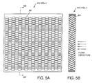
- Figs. 5A and 5B show an example of a total structure of the filter 20 (20a) in this embodiment.
- flow passages 22 each having a passage opening face (cross face) in an oval shape, are aligned in a shape of a staggered lattice.
- the respective flow passages 22 are constituted by holes in a "V"-like shape and are in parallel with each other.
- Such a flow passage 22 can be fabricated by, for example, mechanical working, precision casting, laser machining, electron beam machining or the like. By fabricating the flow passage 22 accurately and uniformly by such a method, a turbulent flow can be rectified. And by changing at least one of a shape of a flow passage opening face, an angle of a flow path, a number of pieces and alignment of flow passage holes, the pressure loss can be adjusted, and thereby, a flow rate of a passing fluid can be adjusted.
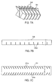
- a filter 30 shown in Figs. 6A, 6B and 6C is constructed by combining pluralities of vertical plates 31 and transverse plates 32 in a lattice shape and aligning these plates like a checker board to thereby form a number of "V"-like (hat-like) flow passages 33 among these plates.
- a plurality of slits 32a are provided along one long side of the transverse plate 32 substantially at equal intervals and in a direction orthogonal to the long side.
- a plurality of slits 31a are provided along long sides on both sides of the vertical plate 31 substantially at equal intervals in parallel with each other.
- the slits 31a on the both sides make predetermined angles relative to the respective long sides.
- a filter 140 shown in Fig. 8C is constructed by overlapping a plurality of sheets of plates (a plate 90a, a plate 90b and so on) each arranged with a plurality of through holes 92 as shown in Figs. 8A and 8B. Positions of making the holes 92 are shifted in the horizontal direction for the respective plates and as shown in Fig. 8C, as a whole, there is formed an alignment of the "V"-like flow paths similar to that shown in Fig. 3.
- the shape of the hole 92 of the respective plate is not limited to a circle as shown in Figs. 8A and 8B but can be constituted by various shapes, and the holes 92 can be constituted by various arrangements such as a square lattice shape illustrated in Fig. 8C as well as a shape of a staggered lattice. According to this embodiment, in comparison with the above-mentioned embodiments such as shown in Fig. 5, fabrication of the filter is facilitated, and waste of the material is inconsiderable by using plate components.
- the through holes are constituted by a "V"-like shape, that is, a shape of the flow passage in which an inlet portion and an outlet portion are constituted by a linear shape and a bent portion is constituted between the inlet portion and the outlet portion.
- a shape of a flow passage by which an outlet of the hole cannot be seen through from an inlet of the hole by a straight line there may also be a flow passage shape having a plurality of bent portions or a flow passage shape which is totally bent without a straight line portion.
- a filter 150 shown in Fig. 9C is constituted by arranging a plurality of sheets of plates (a plate 100a, a plate 100b and so on) each arranged with a plurality of through holes 102 as shown in Figs. 9A and 9B, and arranging the plates substantially in parallel with each other by interposing spacers 104.
- a gap 106 is formed between the respective plates (a plate 100a, a plate 100b and so on) by the spacer 104.
- Positions of the through holes 102 of contiguous two sheets of the plates (100a, 100b) via the gap 106 are shifted from each other in the horizontal direction, thereby, a flow passage shape in which an outlet portion of the passage cannot be seen through from an inlet of the passage by a straight line is constituted.
- Coolant passing through a first hole 102 of the respective plate (100a, 100b or the like) can be directed to another hole 102 of a successive plate, next to the first hole 102, by changing its flow to the horizontal direction at the gap 106.
- a filter 160 based on, for example, the structure of the filter 20 or 20a shown in Fig. 5, is made by fabricating a groove 110 at a vicinity of an inlet portion of the respective through hole 22. According to this embodiment, even when particularly a strip-like foreign substance is caught at a vicinity of the inlet portion of the through hole 22 of the filter 160, the flow passage is ensured by the groove and is not closed.
- a filter 170 shown in Fig. 11 is a modified example of the filter 160 shown in Fig. 10, and instead of fabricating the groove 110 of the filter 160, a groove 111 of the filter 170 is fabricated inclined to an opening face of the flow passage. According to this embodiment, not only an effect the same as that of the filter 160 shown in Fig. 10 is achieved but also an amount of fabrication of the filter is smaller than that in the filter 160 shown in Fig. 10 and waste of material is inconsiderable.
- a filter 180 shown in Fig. 12A based on, for example, the structure of the filter 20 or 20a shown in Fig. 5, is provided projections 112 at a periphery of the inlet portion of the respective hole 22. According to this embodiment, even when particularly, a strip-like foreign substance is caught at a vicinity of the inlet portion of the through hole 22 of the filter 180, the foreign substance is caught by the projection 112 and therefore, the flow passage at the inlet portion of the through hole 22 is ensured and is not closed.
- the groove or the projection is provided at a vicinity of the inlet portion of the respective through hole 22.
- the groove or the projection explained here is also applicable to other embodiments such as those shown in Figs. 6A, 6B, 6C through Figs. 9A, 9B, 9C.
- a filter 190 shown as a plan view in Fig. 13A, composed of the fuel supporting attachment having orifices, is made by assembling vertical plates 113 each in a simple flat plate shape and transverse plates 114 bent in a "V"-like shape at an angle of 90 degrees through 150 degrees, preferably about 120 degrees, at a central portion thereof, substantially in a lattice-like shape, and coolant flow passages 115 are formed by the vertical plates 113 and the transverse plates 114.
- This filter 190 with orifices is constituted to provide a filtration function for preventing a wire-like foreign substance having a length of about 10 millimeters or a plate-like foreign substance having a length of a side thereof of about 10 millimeters from passing through, by assembling the vertical plates 113 and the transverse plates 114 substantially in the lattice-like shape as described above.
- a coolant passes through the filter 190 arranged at the coolant introducing hole 61 of the fuel supporting attachment 60 and flows into the fuel assembly 50 via the coolant flow passage 43. And in this process, a foreign substance included in the coolant is caught by the filter 190 with orifices to thereby prevent the foreign substance from flowing into the fuel supporting attachment 60 and the fuel assembly 50.
- Fig. 13B is a sectional view taken along a line XIIIB-XIIIB of Fig. 13A, showing a state in which the transverse plates 114 are bent in the V-like shape at an angle of about 120 degrees substantially at the central portion.
- the figure in this embodiment shows a constitution of the transverse plate 114 bent in the V-like shape, the constitution of bending a flow direction of the coolant upwardly and downwardly at a plurality of locations is also applicable.
- the flow direction of the coolant may be bent by overlapping a plurality of pieces of lattices, in which the transverse plates 114 are inclined to the flow direction of the coolant in skewed downward directions or skewed upward directions at angles of 15 degrees through 45 degrees, such that a direction of inclination of each traverse plate 114 successively differs.
- Figs. 14A and 14B show another example of a filter 191, which is a modification of the filter shown in Fig. 13A constituted substantially in a square shape, wherein Fig. 14A shows a front face thereof and Fig. 14B shows a section of the filter taken along a line B-B of Fig. 14A.
- the filter 191 is formed by constituting vertical plates 117 and transverse plates 118 in the V-like shape in a lattice-like shape similar to the filter 190. Therefore, operation and effect similar to those shown in Fig. 13A are achieved also by using the filter 191.
- Figs. 15A and 15B show still another example of a filter 192, which is a modification of the filter 191 devised in consideration of fabrication advantages of the filter 191, substantially in a square shape as shown in Fig. 14, and constructed substantially in a lattice-like shape by vertical plates 117 and transverse plates 119.
- Fig. 15A shows a front view
- Fig. 15B shows a section taken along a line B-B of Fig. 15A.
- the transverse plate 119 is constituted by being inclined to a horizontal line at about 30 degrees and by overlapping a plurality of sheets of the filter 192 constituted substantially in the lattice-like shape in this way, and thereby, a constitution similar to that shown in Fig. 14A can be achieved.
- FIG. 16 shows a filter having orifices according to a tenth embodiment of this invention.
- a filter 200 is composed by aggregating a number of pieces of thin-walled circular tubes 121 each having an outer diameter of about 2 millimeters through 5 millimeters in a bundle, and a flow passage constituted by the thin-walled circular tube 121 is bent at 90 degrees through 150 degrees at least at one location or more.
- 17A can be constructed by overlapping a plurality of sheets of plates each having a wall thickness of 5 through 10 millimeters and having a number of circular holes 122 each having a diameter of 2 through 5 millimeters
- a filter 202 with orifices shown in Fig. 17B can be constructed by overlapping a plurality of sheets of plates each having a wall thickness of 5 through 10 millimeters and having a number of rectangular holes 123 each having a side of 2 through 5 millimeters.
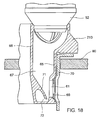
- Fig. 18 shows a sectional view showing a fuel supporting attachment 210 according to an eleventh embodiment of this invention.
- a rectifying portion 71 is arranged at a face of the inner side wall 66 opposed to the coolant introducing hole 61 for turning a flow of a coolant flowing into the fuel supporting attachment 210 from the coolant introducing hole 61 into an upward direction, and a foreign substance storage portion 72 is formed under the rectifying portion 71 to communicate with the coolant flow passage 67 via a lower end edge of the rectifying portion 71.
- the coolant flows into the coolant flow passage 67 via the coolant introducing hole 61 and impinges on the rectifying portion 71 to constitute a flow in an upward direction, meanwhile, a foreign substance contained in the coolant flowing into the coolant flow passage 25 from an upper portion of the fuel supporting attachment 210, is brought into the foreign substance storage portion 72 provided on a lower side of the rectifying portion 71 and is kept to be not lifted by the coolant flow even after starting the operation of the nuclear reactor.
- the filter function can further be promoted by integrating a filter with orifices to the fuel supporting attachment having the foreign substance storage portion.
- a filter installed in the fuel supporting attachment can variously be modified to embody without deviating from technical thought of this invention.
- the fuel supporting attachment may be made of, for example, stainless steel, however, there may also be any other material enough to actualize the structure mentioned above.
- a foreign substance, particularly a linear or a strip-like foreign substance, included in a coolant can be hampered or restrained from flowing to inside of the fuel assembly or to a periphery of the fuel rod, thereby, damages to fuel rods or fuel spacers can firmly be prevented.
- the fuel supporting attachment can be designed to constitute pressure loss quite the same as that in the conventional example without modifying or changing of the fuel assembly per se.
Landscapes
- Physics & Mathematics (AREA)
- Engineering & Computer Science (AREA)
- Plasma & Fusion (AREA)
- General Engineering & Computer Science (AREA)
- High Energy & Nuclear Physics (AREA)
- Filtration Of Liquid (AREA)
- Filtering Materials (AREA)
Abstract
Description
Claims (18)
- A fuel inlet mechanism (10) to introduce a coolant into a fuel assembly (50) configured to be charged in a light water nuclear reactor, comprising:a filter (20a, 30, 140, 150, 160, 170, 180, 190, 200) which catches a foreign substance included in the coolant on an upstream side of the fuel assembly (50);the filter (20a, 30, 140, 150, 160, 170, 180, 190, 200) having a plurality of through holes (1, 2) to pass the coolant; andthe through holes (1, 2) having an inlet portion, an outlet portion and at least one bent portion to a degree by which the outlet portion cannot be seen through from the inlet portion by a straight line.
- The fuel inlet mechanism (10) as recited in Claim 1, wherein the through holes (1, 2) are arranged substantially in parallel with each other.
- The fuel inlet mechanism (10) as recited in Claim 2, wherein the through holes (1) are formed a plurality of plates (31, 32) arranged at intervals and substantially in parallel with each other along a direction of a flow of the coolant.
- The fuel inlet mechanism (10) as recited in Claim 1 or 2, wherein the filter (140) comprises a plurality of overlapped sheets of plates (90a, 90b) having a plurality of holes (92), positions of the holes of the plates differing slightly such that the filter has a coolant passage formed by a series of the holes of the overlapping plates.
- The fuel inlet mechanism (10) as recited in one of Claims 1 through 4, wherein the filter (150) further includes:a plurality of sheets of plates (100a, 100b) respectively containing pluralities of holes (102) and arranged substantially in parallel with each other; anda plurality of filter spacers (104) arranged to form gaps among the plates (100a, 100b); and whereinpositions of the holes (102) of the plates (100a, 100b) slightly differ such that the filter has a coolant passage formed by a series of the holes of overlapping plates and the gaps.
- The fuel inlet mechanism (10) as recited in one of Claims 1 through 5, wherein the filter (160, 170) further includes a groove (110, 111) arranged at a periphery of the inlet portion of a through hole (22).
- The fuel inlet mechanism as recited in one of Claims 1 through 6, wherein the filter (180) further includes a projection (112) at a periphery of the inlet portion of a through hole (22).
- A fuel supporting attachment (60) to hold a fuel assembly (50) configured to be charged in a light water nuclear reactor, comprising:a coolant passage portion (43) to introduce a coolant into the fuel assembly;a control rod introducing hole portion (64) to introduce a control rod into a core of the nuclear reactor;a coolant introducing hole portion (61) arranged at a periphery of a lower part of the fuel supporting attachment (60); anda filter (20a, 190) having an orifice, arranged at the coolant introducing hole portion (61) to intervene a foreign substance included in the coolant to flow into the fuel assembly (50).
- The fuel supporting attachment (60) as recited in Claim 8, wherein the orifice of the filter (20a, 190, 200) is composed in a shape of a lattice which generates a coolant flow passage.
- The fuel supporting attachment (60) as recited in Claim 9, wherein the filter (20a, 190) comprises a plurality of overlapped lattices.
- The fuel supporting attachment (200) as recited in Claim 8, wherein the orifice of the filter (200) is composed by aggregating tubes (121) in a bundle to generate a coolant flow passage inside the tubes (121).
- The fuel supporting attachment (200) as recited in Claim 11, wherein the filter comprises a plurality of the tubes (121).
- The fuel supporting attachment (20a, 190, 191, 192) as recited in one of Claims 8 through 12, wherein the coolant flow passage generated by the orifice is inclined to an inflow direction of the coolant at an inlet portion of the filter.
- The fuel supporting attachment (20a, 190, 191, 192) as recited in one of Claims 8 through 13, wherein the coolant flow passage generated by the orifice includes at least one bent portion relative to an inflow direction of a coolant flow.
- The fuel supporting attachment (60) as recited in Claim 8, wherein the orifice of the filter (20a, 201, 202) comprises a plurality of sheets of overlapping plates, each of which has a plurality of holes (122, 123).
- The fuel supporting attachment (60) as recited in Claim 15, wherein the holes (122, 123) arranged on a plate are substantially in one of a circular shape and a quadrilateral shape.
- A fuel supporting attachment (210) to hold a fuel assembly (50) configured to be charged in a light water nuclear reactor, comprising:a coolant passage portion to introduce a coolant into the fuel assembly (50);a coolant introducing hole portion (61) arranged at a periphery of a lower part of the fuel supporting attachment;a rectifying portion (71) having an inclined face to make a flow of a coolant formed inside the fuel supporting attachment toward the fuel assembly; anda foreign substance storage portion (72) arranged at a lower side of the rectifying portion (71) to catch a foreign substance included in the coolant flowing in from a side of the rectifying portion.
- An arrangement comprising:a fuel assembly (50) configured to be charged in a light water nuclear reactor, including:a plurality of fuel rods (51),an upper tie plate (53) which supports upper ends of the fuel rods (51),a lower tie plate (52) which supports lower ends of the fuel rods (51),a first filter (20) arranged inside of the lower tie plate (52), which catches a foreign substance included in a coolant having a coolant flow path from a lower end side of the lower tie plate (52) as an ascending flow at a periphery of the fuel rods (51); anda fuel supporting attachment (60) which holds the fuel assembly (50), having a second filter (20a, 30, 140, 150, 160, 170, 180, 190, 200) which catches a foreign substance included in a coolant on an upstream side of the fuel assembly; and wherein:the first filter (20) and the second filter (20a, 30, 140, 150, 160, 170, 180, 190, 200) have a plurality of holes (1,2) inside of which the coolant flows, the holes (1,2) including at least one bent portion to a degree by which an outlet portion of a hole cannot be seen through from an inlet portion of the hole by a straight line.
Applications Claiming Priority (6)
| Application Number | Priority Date | Filing Date | Title |
|---|---|---|---|
| JP2001215379 | 2001-07-16 | ||
| JP2001215379 | 2001-07-16 | ||
| JP2001318049 | 2001-10-16 | ||
| JP2001318049A JP2003121579A (en) | 2001-10-16 | 2001-10-16 | Fuel support bracket |
| JP2002147853 | 2002-05-22 | ||
| JP2002147853A JP2003098284A (en) | 2001-07-16 | 2002-05-22 | Fuel inlet structure and fuel assembly |
Publications (2)
| Publication Number | Publication Date |
|---|---|
| EP1278206A2 true EP1278206A2 (en) | 2003-01-22 |
| EP1278206A3 EP1278206A3 (en) | 2010-10-06 |
Family
ID=27347161
Family Applications (1)
| Application Number | Title | Priority Date | Filing Date |
|---|---|---|---|
| EP02015595A Withdrawn EP1278206A3 (en) | 2001-07-16 | 2002-07-15 | Device for supporting a fuel assembly in a nuclear reactor |
Country Status (3)
| Country | Link |
|---|---|
| US (3) | US20030026381A1 (en) |
| EP (1) | EP1278206A3 (en) |
| TW (1) | TW557450B (en) |
Cited By (3)
| Publication number | Priority date | Publication date | Assignee | Title |
|---|---|---|---|---|
| EP1677313A1 (en) * | 2004-12-30 | 2006-07-05 | Global Nuclear Fuel-Americas, LLC | Debris filter |
| RU2328042C2 (en) * | 2006-06-14 | 2008-06-27 | ФГУП Опытное конструкторское бюро "ГИДРОПРЕСС" | Atomic reactor core |
| EP3734614A4 (en) * | 2017-12-28 | 2021-12-01 | Joint-Stock Company "TVEL" | NUCLEAR FUEL BUNDLES |
Families Citing this family (14)
| Publication number | Priority date | Publication date | Assignee | Title |
|---|---|---|---|---|
| KR100624692B1 (en) * | 2004-09-13 | 2006-09-15 | 삼성전자주식회사 | An inkjet head filter plate, an inkjet head having the filter plate, and a manufacturing method of the filter plate |
| US8116423B2 (en) | 2007-12-26 | 2012-02-14 | Thorium Power, Inc. | Nuclear reactor (alternatives), fuel assembly of seed-blanket subassemblies for nuclear reactor (alternatives), and fuel element for fuel assembly |
| AU2007363064B2 (en) | 2007-12-26 | 2014-02-13 | Thorium Power Inc. | Nuclear reactor (variants), fuel assembly consisting of driver-breeding modules for a nuclear reactor (variants) and a fuel cell for a fuel assembly |
| ATE515776T1 (en) * | 2008-09-16 | 2011-07-15 | Areva Np | DEBRIS FILTER FOR RETENTION OF SOLID PARTICLES IN THE COOLANT LIQUID OF A NUCLEAR REACTOR |
| JP5755568B2 (en) | 2008-12-25 | 2015-07-29 | トリウム・パワー、インクThorium Power,Inc. | Light water reactor nuclear fuel assembly and light water reactor |
| US10170207B2 (en) | 2013-05-10 | 2019-01-01 | Thorium Power, Inc. | Fuel assembly |
| WO2011143172A1 (en) | 2010-05-11 | 2011-11-17 | Thorium Power, Inc. | Fuel assembly with metal fuel alloy kernel and method of manufacturing thereof |
| US10192644B2 (en) | 2010-05-11 | 2019-01-29 | Lightbridge Corporation | Fuel assembly |
| WO2012073461A1 (en) * | 2010-12-03 | 2012-06-07 | 原子燃料工業株式会社 | Debris filter |
| US20120163526A1 (en) * | 2010-12-28 | 2012-06-28 | Global Nuclear Fuel - Americas, Llc | Optimized fuel supports and methods of creating reactor cores with the same |
| EP2525362A1 (en) | 2011-05-20 | 2012-11-21 | Areva NP | Debris filter for nuclear reactor installation and nucluar fuel assembly comprising such a debris filter |
| US8714722B2 (en) * | 2012-07-20 | 2014-05-06 | Xerox Corporation | Multiple layer filter |
| EP3510601B1 (en) * | 2016-09-06 | 2021-05-12 | Westinghouse Electric Sweden AB | A fuel assembly |
| US10923237B2 (en) * | 2017-08-28 | 2021-02-16 | Global Nuclear Fuel—Americas, LLC | Debris filters for nuclear fuel assembly and method of using the same |
Family Cites Families (17)
| Publication number | Priority date | Publication date | Assignee | Title |
|---|---|---|---|---|
| US4255236A (en) * | 1977-11-01 | 1981-03-10 | Robbins Thomas R | Reactor and fuel assembly design for improved fuel utilization in liquid moderated thermal reactors |
| JPS57182195A (en) * | 1981-05-06 | 1982-11-09 | Hitachi Ltd | Reactor core |
| JPS61284696A (en) * | 1985-06-12 | 1986-12-15 | 株式会社日立製作所 | Reactor |
| SE465191B (en) * | 1989-12-14 | 1991-08-05 | Asea Atom Ab | BRAENSLEPATRON CARRIES A CORE WATER TYPE REACTOR |
| SE465192B (en) * | 1989-12-15 | 1991-08-05 | Asea Atom Ab | BRAENSLEPATRON CARRIES A NUCLEAR WATER TYPE REACTOR |
| US5045272A (en) * | 1990-02-16 | 1991-09-03 | Westinghouse Electric Corp. | Fluid temperature balancing system |
| US5030412A (en) * | 1990-05-04 | 1991-07-09 | Advanced Nuclear Fuels Corporation | Fuel assembly debris screen |
| US5420897A (en) * | 1992-07-30 | 1995-05-30 | Kabushiki Kaisha Toshiba | Fast reactor having reflector control system |
| US5282231A (en) * | 1992-09-23 | 1994-01-25 | Siemens Power Corporation | Lower tie plate cast frame |
| DE4240537A1 (en) * | 1992-12-02 | 1994-06-09 | Siemens Ag | Method for producing a screen plate for a fuel assembly base and corresponding fuel assembly |
| US5345483A (en) * | 1993-12-02 | 1994-09-06 | General Electric Company | Lower tie plate strainers having double plate with offset holes for boiling water reactors |
| US5481577A (en) * | 1994-06-30 | 1996-01-02 | Siemens Power Corporation | Boiling water reactor fuel assembly filter |
| US5479461A (en) * | 1994-06-30 | 1995-12-26 | Siemens Power Corporation | Attachable debris filter for BWR nuclear fuel assemblies |
| DE29615575U1 (en) * | 1996-09-06 | 1997-01-16 | Siemens AG, 80333 München | Fuel element with debris filter |
| JP3504857B2 (en) * | 1998-06-19 | 2004-03-08 | 株式会社日立製作所 | Operating method of boiling water reactor |
| JP2000284080A (en) * | 1999-03-31 | 2000-10-13 | Nuclear Fuel Ind Ltd | Fuel assemblies for boiling water reactors |
| JP2002122687A (en) * | 2000-10-17 | 2002-04-26 | Toshiba Corp | Reactor core and reactor operating method |
-
2002
- 2002-07-08 TW TW091115045A patent/TW557450B/en not_active IP Right Cessation
- 2002-07-15 US US10/195,126 patent/US20030026381A1/en not_active Abandoned
- 2002-07-15 EP EP02015595A patent/EP1278206A3/en not_active Withdrawn
-
2005
- 2005-08-22 US US11/207,777 patent/US20050276367A1/en not_active Abandoned
-
2007
- 2007-09-10 US US11/852,528 patent/US20080130820A1/en not_active Abandoned
Cited By (4)
| Publication number | Priority date | Publication date | Assignee | Title |
|---|---|---|---|---|
| EP1677313A1 (en) * | 2004-12-30 | 2006-07-05 | Global Nuclear Fuel-Americas, LLC | Debris filter |
| RU2328042C2 (en) * | 2006-06-14 | 2008-06-27 | ФГУП Опытное конструкторское бюро "ГИДРОПРЕСС" | Atomic reactor core |
| EP3734614A4 (en) * | 2017-12-28 | 2021-12-01 | Joint-Stock Company "TVEL" | NUCLEAR FUEL BUNDLES |
| US11437154B2 (en) | 2017-12-28 | 2022-09-06 | Joint-Stock Company “Tvel” | Nuclear fuel assembly having a filter for retention of foreign objects in the coolant |
Also Published As
| Publication number | Publication date |
|---|---|
| TW557450B (en) | 2003-10-11 |
| US20030026381A1 (en) | 2003-02-06 |
| EP1278206A3 (en) | 2010-10-06 |
| US20080130820A1 (en) | 2008-06-05 |
| US20050276367A1 (en) | 2005-12-15 |
Similar Documents
| Publication | Publication Date | Title |
|---|---|---|
| US20080130820A1 (en) | Fuel supporting attachment and fuel inlet mechanism | |
| US5345483A (en) | Lower tie plate strainers having double plate with offset holes for boiling water reactors | |
| US5283812A (en) | Bottom nozzle of a fuel assembly for a water-cooled nuclear reactor | |
| EP0620558B2 (en) | Debris catching grid construction for a fuel bundle of a boiling water reactor | |
| US5167909A (en) | Lower connector of a fuel assembly of a nuclear reactor cooled by light water | |
| EP0669624B1 (en) | Debris catcher for a nuclear reactor | |
| JP3977532B2 (en) | Fuel assemblies, reactor cores and channel boxes | |
| US11183310B2 (en) | Bottom nozzle of nuclear fuel assembly provided with flow holes by utilizing layered aircraft airfoil structure | |
| US5539793A (en) | Lower tie plate debris catcher for a nuclear reactor | |
| EP0655746A1 (en) | Strainers for boiling water reactors | |
| KR20210039748A (en) | A bottom Fixture of Nuclear Fuel Assembly formed flow hole by a Aircraft Airfoil Structure forming a flow hole | |
| EP0528621B1 (en) | Hydride resistant spacer formed from interlocking strips for a nuclear fuel assembly of a boiling water reactor | |
| US6650723B1 (en) | Double strip mixing grid for nuclear reactor fuel assemblies | |
| US6385271B2 (en) | Nuclear fuel assembly | |
| US6721384B2 (en) | Spacer grid with side welding support and flow mixing vane for nuclear reactor fuel assembly | |
| US20140016735A1 (en) | Spacer and a fuel unit for a nuclear plant | |
| US6744843B2 (en) | Side-slotted nozzle type double sheet spacer grid for nuclear fuel assemblies | |
| JP2004509322A (en) | Spacer grid for pressurized water reactor fuel assembly | |
| US20040005025A1 (en) | Spacer grid with double deflected vanes for nuclear fuel assemblies | |
| EP0710960A1 (en) | Lower tie plate debris catcher for a nuclear reactor | |
| KR102413698B1 (en) | A bottom Fixture of Nuclear Fuel Assembly formed flow hole by a Aircraft Airfoil Structure forming a flow hole | |
| EP1706875B1 (en) | A spacer and a fuel unit for a nuclear plant | |
| US5471514A (en) | Fuel element for a light-water nuclear reactor | |
| US5483565A (en) | Fuel assembly for a boiling water reactor | |
| EP1986197B1 (en) | Pressurized water reactor fuel assembly |
Legal Events
| Date | Code | Title | Description |
|---|---|---|---|
| PUAI | Public reference made under article 153(3) epc to a published international application that has entered the european phase |
Free format text: ORIGINAL CODE: 0009012 |
|
| 17P | Request for examination filed |
Effective date: 20020715 |
|
| AK | Designated contracting states |
Kind code of ref document: A2 Designated state(s): AT BE BG CH CY CZ DE DK EE ES FI FR GB GR IE IT LI LU MC NL PT SE SK TR |
|
| AX | Request for extension of the european patent |
Free format text: AL;LT;LV;MK;RO;SI |
|
| RIC1 | Information provided on ipc code assigned before grant |
Ipc: 7G 21C 3/32 B Ipc: 7G 21C 5/06 A |
|
| PUAL | Search report despatched |
Free format text: ORIGINAL CODE: 0009013 |
|
| AK | Designated contracting states |
Kind code of ref document: A3 Designated state(s): AT BE BG CH CY CZ DE DK EE ES FI FR GB GR IE IT LI LU MC NL PT SE SK TR |
|
| AX | Request for extension of the european patent |
Extension state: AL LT LV MK RO SI |
|
| AKX | Designation fees paid |
Designated state(s): DE SE |
|
| 17Q | First examination report despatched |
Effective date: 20110628 |
|
| STAA | Information on the status of an ep patent application or granted ep patent |
Free format text: STATUS: THE APPLICATION IS DEEMED TO BE WITHDRAWN |
|
| 18D | Application deemed to be withdrawn |
Effective date: 20120110 |