Field of the Invention
This invention relates to a portable data collection device adapted for mounting
on a shopping cart and, more particularly, a portable data collection device adapted for
mounting on a shopping cart and including a retractable, tethered selectively actuatable
dataform reader attached to a housing of the portable data collection device.
Background of the Invention
In a retail store or grocery store, a customer will typically push a shopping cart
through the aisles selecting items of merchandise. When the shopper is finished, he
or she proceeds to a cash register/data terminal in a check-out area of the store. The
cash register/data terminal typically includes a hand held and/or fix mounted dataform
reading and decoding assembly ("dataform reader"). If a fix mounted dataform reader
is being used, a store clerk presents each item's bar code dataform to the dataform
reader, that is, the dataform is moved along an upper surface of a glass window under
which the dataform reader is mounted. If a hand held dataform reader is being used,
the clerk "aims" the reader at each item's dataform as the item moves past the
terminal. In each case, a "good read and decode" signal will be actuated after each
successful dataform read and decode to notify the clerk that the item's dataform was
successfully read and decoded. The signal may be an audible tone or "beep". If no
"beep" is heard, the clerk will repeat the reading process for the item until successful.
Each item's dataform includes a product identifier which is used to retrieve a
product description and price of the item from a remote database. A visual display on
the terminal displays the item's product description and price for each item upon
reading and decoding the dataform. When all the items being purchased by a customer
have been presented to the reader, the terminal provides a total price for all the
customer's items and prints a register receipt listing a product description for each item
and its price, a subtotal for all items, a tax amount and a total amount due. The
amount tendered by the customer is input by the clerk using a terminal keypad. The
amount tendered and change due are also printed on the register receipt. The clerk
collects payment from the customer and dispenses any change.
A number of problems are associated with such a cash register/data terminal
system including: (1) inconvenience for customers waiting in long check-out lines; (2)
use of valuable floor space for the check-out area when a number of cash register/data
terminals are utilized; and (3) product prices have to be either printed on labels affixed
to each item or marked on shelving adjacent the item's shelf space so a customer knows
the price of a selected item.
In one proposed alternative system, a customer is presented with a portable
hand held data terminal including a hand held dataform reader when he or she enters
the store. The customer uses the reader to read a bar code dataform on each item prior
to or concurrently with placing the item into his or her shopping cart. A memory in
the portable data terminal stores a retrieved product description and price for each
selected item. At the check-out area, a store clerk merely prints a register receipt
based on the data stored in the dataform reader and collects payment from the
customer.
There are a number of disadvantages associated with this proposed alternative
portable data terminal system. First, the customer must carry the data collection
device during the shopping session. The device represents another item which must be
handled by the customer in addition to the shopping cart, items being purchased and
possibly children. This is inconvenient for the customer and can lead to the device
being damaged through mishandling or dropping of the device by a hurried customer.
Second, the retailer must dedicate floor space to the entrance area where the devices
are presented to and collected from customers. Third, the device is susceptible to
being stolen.
What is needed is a more convenient system for providing customers with a
portable data collection device including a dataform reader which can be used by a
customer to read dataforms of items selected for purchase during a shopping session.
According to a first aspect of the present invention, there is provided a display
terminal adapted to be mounted on a shopping cart as defined in claim 1.
According to a second aspect of the present invention, there is provided a user-interactive
display system as defined in claim 13.
In one aspect a portable data collection device comprises
Preferably, the housing
includes a clamping mechanism for releasably affixing the device to a shopping cart.
Preferably, the dataform
reader is releasably coupled to the housing with a retractable electrical cable.
Preferably, the visual display
screen includes a touch sensitive panel which functions as the input means.
Preferably, the electronic
circuitry is electrically coupled to a power source spaced apart from the housing.
Preferably, the retrieved data
includes the price and product name of the item whose dataform was read and decoded.
More preferably, the price and
product name of the item is displayed on the visual display screen.
More preferably still, the device is
employed to read and decode dataforms affixed to a plurality of items and, for each
item, the price and product name of the item is retrieved from the remote device and
displayed on the visual display screen and the processor additionally displays a total
sum of the prices for all of the items whose dataforms were read and decoded.
Alternatively, the device further
includes a printing assembly for printing out a receipt including a price and product
name for each item whose dataform was read and decoded.
In embodiments wherein the visual desploy includes a touch sensitive panel the visual display
screen displays a screen layout including a virtual keyboard comprised of a plurality
of alphabetic keys and wherein a user of the device sequentially touches a series of the
alphabetic keys to input data or commands to the processor.
Preferably, the visual display
screen displays a screen layout including blocks containing indicia and wherein a user
of the device touches a selected block to input a command to the processor.
Preferably, the visual display
screen displays a screen layout including a virtual keyboard comprised of a plurality
of alphabetic keys and wherein a user of the device sequentially touches a series of the
alphabetic keys to obtain additional data associated with the item.
Preferably, the visual display
screen displays a screen layout including blocks containing indicia and wherein a user
of the device touches a selected block to obtain additional data associated with the item.
More preferably, at least one of
the blocks, when touched, causes a recipe using the item to be displayed on the display
screen.
Preferably, the electronic
circuitry additionally includes a magnetic stripe reading and decoding module and the
housing includes an aperture adapted to receive a magnetic stripe portion of a credit
card passed through the aperture and the magnetic stripe module includes a magnetic
stripe reader positioned proximal to the aperture to read a magnetic stripe passed
through the aperture.
In another aspect a portable data collection device comprises:
Preferably, the device further includes a
clamping mechanism for releasably affixing the terminal to a shopping cart.
Preferably, the electrical
circuity is electrically coupled to a power supply spaced apart from the housing and
supported by the shopping cart.
Preferably, the device further includes a touch
sensitive panel overlying at least a portion of the visual display screen for inputting
commands to the electrical circuitry.
Preferably, the derive further includes a
magnetic stripe reading assembly including a slotted portion of the housing for
receiving a magnetic stripe portion of a card and a magnetic stripe reader positioned
adjacent the slotted portion of the housing for reading the magnetic stripe portion of
a card inserted in the slotted portion of the housing.
Preferably, the visual
display comprises a liquid crystal display screen.
Preferably, the data
retrieved from the remote device includes a price and a product name of the item.
Preferably, the camera
assembly is electrically coupled to the electrical circuitry of the device disposed in the
housing by an electrical cable.
More preferably, a recoil
mechanism is supported in the housing and functions to dispense cable wrapped around
a spool of the recoil mechanism as the camera assembly is moved away from the
housing and to retract the cable and wind the cable around the spool as the camera
assembly is moved toward the housing.
In a preferred embodiment the housing
includes an opening sized to receive at least a portion of the camera assembly.
A portable data collection device including a hand held dataform reader is disclosed.
The device includes a housing having a clamping mechanism for securely clamping
the housing to a pushing bar of a shopping cart. The housing defines an interior region
in which electrical circuitry of the device is disposed. The device further includes a
hand held dataform reader which is tethered with a retractable electrical cable to the
housing. The reader operates in two modes; a presentation mode and a hand held
mode. When the dataform reader is disposed in an opening in the housing, the
reader's imaging and illumination assemblies are continuously
actuated to read a dataform of an item presented to the reader. This is referred to as
the presentation mode. In the hand held mode of operation, the reader is pulled from
the opening in housing. When the reader is pulled away from the housing, the imaging
and illumination assemblies are deactivated. The customer moves the reader so as to
"aim" it at a selected items dataform. A trigger on the reader is depressed to actuate
the reader's imaging and illumination assemblies. The illumination assembly includes
a targeting assembly to aid in aiming the reader at the target dataform. When the
imaging assembly generates a decodable image of the dataform, decoding circuitry
disposed in the housing decodes the imaged dataform. When the dataform is
successfully read and decoded, a speaker mounted in the housing emits an audible tone
or "beep" to indicate to the customer that the item's dataform has been read and
decoded. The reader is then returned to its position in the housing opening. The cable
connecting the reader and electrical circuitry in the housing is automatically recoiled
by a recoil mechanism in the housing.
The reader includes the illumination assembly for illuminating a selected item's
dataform with a plurality of illumination LEDs and also includes targeting LEDs which
generate a "crosshair" pattern for properly aiming the device at the target dataform.
The crosshair pattern size substantially corresponds to the field of view or target area
of the imaging assembly. The illumination assembly also includes a lens array for
properly focusing the light emitted by the illumination and targeting LEDs over an area
substantially corresponding to the field of view or target area of the imaging assembly.
The imaging assembly is preferably a two dimensional charge coupled device
imaging assembly including a board camera assembly with a two dimensional
photosensor array. The imaging assembly further includes a control and decoder
printed circuit board on which circuitry is mounted including a microprocessor for
controlling operations of the device and image processing and decoding circuitry for
processing and decoding the dataform image from a composite analog video signal
generated by the board camera assembly. The imaging assembly of the present
invention may be used to read both one and two dimensional bar code dataforms as
well as matrix dataforms (MaxiCode, Data Matrix, Code 1, etc.). A one dimensional
bar code comprises one horizontal line of alternating vertically oriented black and white
bars of varying widths, e.g., UPC bar code while a two dimensional bar code consists
of a plurality of horizontal lines of bar code, e.g., PDF-417, Supercode, etc.
As noted above, the electrical circuitry of the portable data collection device
includes the microprocessor for controlling operations of the device. The circuitry also
includes the image processing and decoding circuitry for decoding a dataform read by
the dataform reader and communications circuitry for sending data to and receiving
data from remote devices. The housing also supports a visual display screen with a
touch sensitive overlying layer providing for user interface with the microprocessor.
When an item's dataform is read, the item's price and product description is retrieved
from a remote database and displayed on the visual display screen. The
communications circuitry, including a radio frequency (rf) transceiver module,
retrieves the item's price and product description via a cellular communications
network of which the device is a part. At the end of a shopping session, a listing of
all items and their product descriptions and prices are displayed
on the screen and a customer receipt is printed by a printing assembly disposed in the
housing.
The device display screen displays a number of screen menus and associated
touch sensitive response blocks and/or virtual keypads and keyboards for user input of
data and commands to the device. Menu driven options presented to a customer
include selecting recipes for an item whose dataform was read and ordering prepared
items from the store's delicatessen, meat department, etc. The communications
circuitry permits a location of the device to be monitored for security purposes.
These and other advantages and features of this invention will be clearly
understood through consideration of the following detailed description of the invention
in conjunction with the accompanying drawings.
Brief Description of the Drawings
Figure 1 is a perspective view of a portable data collection device of the present
invention as mounted on a shopping cart with a dataform reader of the device being
employed in a hand held mode;
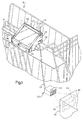
Figure 2 is another perspective view of the portable data collection device of
Figure 1 as mounted on the shopping cart with the dataform reader of the device being
employed in a presentation mode;
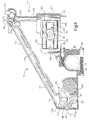
Figure 3 is a view, partly in section and partly in elevation, of the portable data
collection device of Figure 1;
Figure 4 is a view, partially in section and partly in top plan, of the retractable,
tethered dataform reader of the portable data collection device of Figure 1;
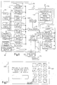
Figure 5 is a schematic representation of selected electronic modules and
circuitry of the portable data collection device of Figure 1;
Figure 6 is a flow chart representing processing steps of the portable data
collection device of Figure 1 in connection with a shopping session at a retail store
using the device;
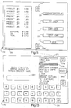
Figure 7 is a representative welcoming display displayed on a touch sensitive
display screen of the portable data collection device of Figure 1;
Figure 8 is a representative introductory menu displayed on the touch sensitive
display screen of the portable data collection device of Figure 1 in connection with a
shopping session;
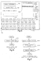
Figure 9 is a representative menu displayed on the touch sensitive display screen
of the portable data collection device of Figure 1 after an item's bar code dataform has
been read;
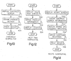
Figure 10 is a flow chart representing processing steps of the portable data
collection device of Figure 2 in connection with a routine for checking out items
selected for purchase;
Figure 11 is a representative screen layout displayed on the touch sensitive
display screen of the portable data collection device of Figure 1 in connection with a
routine for checking out items selected for purchase;
Figure 12 is a flow chart representing processing steps of the portable data
collection device of Figure 1 in connection with a help routine for aiding a customer
find a desired item;
Figure 13 is a representative screen layout displayed on the touch sensitive
display screen of the portable data collection device of Figure 1 in connection with a
help routine for aiding a customer find a desired item;
Figure 14 is a flow chart representing processing steps of the portable data
collection device of Figure 1 in connection with a routine for providing a recipe using
a selected food item;
Figure 15 is a representative screen layout displayed on the touch sensitive
display screen of the portable data collection device of Figure 1 in connection with a
routine for providing a recipe using a selected food item;
Figure 16 is a flow chart representing processing steps of the portable data
collection device of Figure 1 in connection with a routine for displaying a layout of the
retail store the portable data collection device of Figure 1 is used in;
Figure 17 is a flow chart representing processing steps of the portable data
collection device of Figure 1 in connection with a routine for permitting a customer to
order a prepared item during a shopping session;
Figure 18 is a representative screen layout displayed on the touch sensitive
display screen of the portable data collection device of Figure 1 in connection with a
routine for permitting a customer to order a prepared item during a shopping session;
Figure 19 is a schematic representation of communication cells of a cellular
communications system utilized by a spread spectrum communications circuitry of the
portable data collection device of Figure 1;
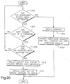
Figure 20 is a flow chart representing processing steps of the portable data
collection device of Figure 1 in connection with a routine for providing customer
assistance and monitoring a location of the shopping cart;
Figure 21 is an alternate embodiment a portable data collection device of the
present invention mounted on a shopping cart; and
Figure 22 is another alternate embodiment of a portable data collection device
of the present invention mounted on a shopping cart.
Detailed Description
A portable data collection device of the present invention is shown generally in
Figures 1 and 2. The device 10 includes a housing 12 supporting an interactive touch
sensitive display screen 14. The housing 12 is mounted on a pushing handle 16 of a
shopping cart 18. The interactive touch display screen 14 is mounted to be visible
through an opening in an inclined front surface 20 of the housing 12. The display
screen 14 is at a proper angle for easy viewing by a customer having his or her hands
on the shopping cart handle 16.
A dataform reading assembly including a hand held bar code dataform reader
22 is retractively tethered or attached to the housing 12 with an electrical cable 24.
The cable 24 includes a plurality of conductors 140 (Figure 4) for supplying power to
the reader 22, coupling a composite analog video signal 28 (Figure 5) representing a
bar code dataform 30 (shown in phantom in Figure 1 and in top plan in Figure 4) to
a processor 32 mounted on a control and decoder printed circuit board 33 (Figure 3 and
schematically in Figure 5) in the housing 12. The circuitry on the control and decoder
board 33 and the dataform reader 22 comprise a dataform reading and decoding
assembly.
The dataform reader 22 operates in two modes: a) a hand held mode; and b) a
presentation mode. The hand held mode of operation is represented in Figure 1
wherein the reader 22 is removed by the customer from an opening 36 in a side 38 of
the housing 12. When supported in the opening 36, the reader 22 extends slightly
beyond the side 38 so that the customer can easily grasp a front portion of the reader
and slide it out of the opening. The customer moves the reader 22 to a dataform 30
of an item so desired to be purchases or priced by the customer. The customer
depresses a trigger 40 to actuate an imaging assembly 42 and an illumination assembly
44 of the reader 22. The illumination assembly 44 provides a uniform illumination
pattern that substantially corresponds to an imaging area or field of view 46 of the
imaging assembly 42 and additionally generates a more intense crosshair illumination
pattern 48 to aid the customer in positioning the reader 22 so that the dataform 30 of
an item 50 is properly within the imaging area of the reader. The uniform illumination
pattern and crosshair aiming pattern are rapidly alternated between off and on states,
such that one is off while the other is on. This alternation of illumination pattern
avoids the difficulty of having to decode a captured dataform image which has an
intense crosshair illumination pattern imposed thereon. The alternation of the
illumination and crosshair patterns is rapid enough that it appears to the customer that
the crosshair aiming pattern is continuously on.
While keeping the trigger 40 depressed, the customer aims the crosshair pattern
48 at a center of the dataform 30. The customer moves the reader 22 toward the item
50 until an audible tone or "beep" is emitted by a speaker 130 indicating that the
dataform 30 has been successfully read and decoded. The item's price and product
name or description and product size will appear on the display 14 (see Figure 9 and
block 222). After the "beep" is heard, the reader 22 is returned to the opening 36 and
slid in.
In the presentation mode of operation, the reader 22 is disposed in the housing
opening 36 the customer reads a dataform 52 affixed to an item 54 by moving the item
to the reader 22. While the reader 22 remains in the housing opening 36, a magnetic
switch 158 (Figure 4) enclosed in a back portion of a modular housing 142 of the
reader 22 is turned on by a magnet 160 positioned in the opening 36 when the reader
is in the opening. Actuation of the magnetic switch 158 causes the imaging assembly
42 and the illumination assembly 44 to be actuated. Thus, the reader 22 is
continuously ready to read a dataform when it is disposed in the opening 36. When
a "beep" is heard, the customer knows that the dataform 52 has been successfully
imaged and decoded. In this mode, the illumination pattern is continuously on and the
crosshair illumination pattern is deactivated since properly "aiming" the reader 23 is
not a concern. The hand held mode is advantageously used when an item on a shelf
is too large or too clumsy to move from the shelf or if the customer just wishes to
check a price without removing the item from the shelf. The presentation mode is
advantageously employed when a selected item is smaller and more easily handled.
A magnetic stripe reader 60 is molded into an upper surface 125 of the housing
12. The stripe reader 60 includes a slotted opening 61a in the upper surface and
includes a stripe sensor and reader 61b (Figure 3) disposed along the opening.
Appropriate magnetic stripe decoding circuitry (Figure 5) is mounted on the control
and decoder board 33. The magnetic stripe reader 60 is used in connection with a
customer identification subroutine to be discussed below. The housing 12 also supports
a thermal printing assembly 62 (Figure 3) which functions to print out a paper receipt
63 for the customer at the completion of shopping session or a recipe for an item. The
printing assembly 62 discharges the receipt or recipe printout through a slot shaped
opening 64 in an upright front surface 66 of the housing 12. An assistance request
button 68 extending through an opening in the inclined front surface 20 of the housing
12 is activated by a shopper to request assistance from store personnel as will be
discussed below in connection with Figure 20.
The device 10 also includes a high capacity battery 70 (Figure 2) which is
mounted in a case disposed on a bottom rack 72 of the shopping cart 18. The battery
70 preferably uses lead-acid technology because of its low cost, high energy capacity
and lack of memory effect. The weight associated with a lead-acid battery is not a
concern because it is mounted on the cart 18. A typical 6 volt, three cell lead-acid
battery such as the type used on a motorcycle, has an energy capacity sufficient to
power the device 10 for a time period in excess of 24 hours. A power lead 74 connects
the battery 70 to power circuitry 76 (shown schematically in Figure 5) in the housing
12.
Figure 3 is a view, partly in section and partly in elevation, of the housing 12.
The device 10 is secured to the shopping cart handle 16 by a clamping assembly which
clamps the housing 12 to the cart pushing handle 16. The clamping assembly includes
adjustable clamp 80 and an arcuate clamping surface 82 of the housing 12. Two sets
of two threaded bolts 84, 86 (only one set of two threaded bolts can be seen
in Figure 3) extend between the clamp 82 and threaded openings in the housing 12 to
secure the adjustable clamp 82 to the housing 12. When the two sets of threaded bolts
84, 86 are tightened, the housing 12 is secured to the pushing handle 16 of the cart 18.
The thermal printer assembly 62 includes a thermal printhead 90 and an
opposing platen 92 to position the paper 63 against the printhead 90. A motor 94
drives a feed roller 96. The feed roller 96 operates in conjunction with an idler roller
98 to draw paper 63 from a paper roll 100 past the printhead 90 and feed the receipt
or recipe printout 63 out of the slot shaped opening 64 in the housing 12. Printer
driver circuitry 101 for operating the printer assembly components is mounted on the
control and decoder printed circuit board 33 disposed in the housing 12. At least a
portion of the circuitry 101 may be embodied in code stored in a memory 106
represented by a memory chip on the control and decoder printed circuit board 33 and
executed by the processor 32, both on printed circuitry board 102.
The user interactive display screen 14 includes a liquid crystal display (LCD)
display panel 110 and an overlying touch sensitive resistive contact panel 112.
Circuitry for operating the screen 14 and the panel 112 includes LCD driver circuitry
114 and contact panel driver circuitry 116. Additionally, the circuitry 114, 116 for
operating the LCD display and contact panels 110, 112 may, at least in part, be
implemented in software stored in the memory 106 and executed by the processor 32.
The spread spectrum radio communications circuitry 118 may be embodied in
one or more IC chips mounted on the printed circuit board 33. Alternatively, the
spread spectrum communications circuitry 18 may be implemented on a separate
printed circuit board with a PCMCIA interface and secured to the printed circuit board
102 through a PCMCIA standard slot interface. An antenna lead 122 connects the
communications circuitry to an antenna mast 124 extending through an opening in the
upper surface 125 of the housing 12. Alternatively, the antenna mast could be disposed
inside the housing. The communications circuitry 118 includes a radio frequency (rf)
radio transceiver module which communicates decoded bar code data to a host
computer 1260 (schematically shown in Figure 19) utilizing a spread spectrum cellular
radio network (also shown schematically in Figure 19). The decoded data includes a
product identifier encoded in the item's dataform. In turn the transceiver module
receives data relating to the item from the host computer 1260, e.g., a product name
or description for the item, the price of the item, etc. The host computer 1260
retrieves the data from a database containing product information which includes the
product identifier as a search key.
As previously discussed, power to operate the device 10 is supplied by the
battery 70 disposed on the bottom rack 72 of the shopping cart 18. The power lead 74
interconnects the battery 70 to power supply circuitry 76 mounted on the control and
decoder board 33 within the housing 12. The housing 12 also includes a power supply
port 128 where an external power source may be connected for charging the battery 70.
The power supply circuitry 76 controls charging and controls converting the battery
power supply to appropriate electrical parameters for use by various circuitry and
electronic modules of the device 10.
The housing 12 also supports the speaker 130 which is mounted behind a grated
opening 132 in the housing 12. The speaker 130 is driven by audio indicator
driver circuitry 134 mounted on the control and decoder board 33 and provides audio
feedback in the form of a ½ second "beep" to the customer to indicate a successful bar
code dataform read and decode.
Figure 4 is a cut-away view of the reader 22 and a portion of the device 10 in
the region of the opening 36 showing details of a recoil or cable retraction mechanism
138 of the dataform reader 22. The reader 22 is connected to the housing 12 with the
cable 24. The cable 24 includes the plurality of conductors 140 for: a) coupling
operating power 26 to the reader 22; b) coupling the composite video signal 28 from
the reader 22 to the processor 32; and c) coupling control signals from the processor
32 to the reader 22. The cable 24 is secured to a housing 142 of the reader with a
clamping grommet 144 to prevent the reader 22 from being physically separated from
the cable 24.
The reader housing 142 is a modular unit that includes a top half and a mating
bottom half. Only the bottom half of the reader housing is shown in Figure 4 so that
the internal components of the reader 22 are visible in the Figure. To further secure
the reader 22 to the cable 24, a knot (not shown) may be tied in the cable just inside
the reader housing 142. The plurality of conductors 140 are electrically coupled to a
printed circuit board 146 within the reader housing 142 by a connector 148.
Within the housing 12, the cable 24 is wrapped around a recoil spool 150. The
recoil spool 150 spins about a center pin 152 of the spool. The pin 152 is a hollow
cylinder such that the cable 24 may be threaded through the pin 152 and connected to
circuitry within the housing 12. A spirally wound bias spring 154 is secured to the pin
152 at the center of the recoil spool 150 and to the spring tab 156 at the perimeter
of the re-coil spool 150 to bias the spool in a counter clockwise direction (as viewed
in Figure 4). This arrangement keeps the cable 24 under tension when the reader 22
is removed from the housing opening 20.
As discussed previously, the reader 22 includes a user trigger 40 (shown in
Figure 1) which is depressed by the customer to initiate a bar code reading session
when the reader is being used in the hand held mode. The trigger 40 prevents the
reading of unintended dataforms. As the reader 22 is being moved to and aimed at a
desired dataform. When the reader 22 is positioned in the housing opening 36 of the
console housing 12, the trigger 40 is not accessible. Furthermore, because the reader
22 is intended to be used to read a dataform of any item presented to the reader, a
manually activated read button is impractical. Therefore, a magnetic switch 158 in the
reader housing 142 is "tripped" to an on state by a magnet 160 mounted just inside of
the housing wall 162 defining the opening 36 when the reader 22 is positioned in the
opening. The magnetic switch 158 causes the imaging assembly 42 and the
illumination assembly 44 of the reader 22 to be actuated. The edge formed by the
housing wall 162 and the side wall 38 is rounded (Figure 4) to avoid wearing an outer
surface of the cable 24.
The reader 22 is preferably utilizes a two-dimensional imaging assembly. The
imaging assembly 42 includes a two-dimensional photosensor array 170 (Figure 4) and
an optic assembly supported in a lens housing or shroud 172 for focusing an image of
the dataform 30 in the target area 46 onto the photosensor array 170. Circuitry on
printed circuit boards 174, 176 and 146 operate to sequentially read out charges
accumulating on photosensors of the photosensor array 104 and generate the analog
composite video signal 28 representative of consecutive frames of the imaged dataform
30. The video signal 28 is coupled to image processing circuitry 178 disposed on the
control and decoder printed circuit board 33 which converts a portion of the composite
video signal representing a captured image frame into a series of gray scale values
whose magnitudes represent the relative reflectivity of portions of the imaged dataform
30.
The image processing circuitry 178 then performs cell extraction analysis to
reconfigure the imaged dataform in the memory 106. The decoding circuitry 34 then
decodes the representation of the imaged dataform stored in the memory 106. At least
a portion of the image processing and decoding circuitry may be implemented in code
executed by the processor 32.
The illumination assembly 44 of the reader 22 includes four sets of four surface
mount illumination LEDs 180 positioned on a printed circuit board 182 (only two sets
of the four sets of four illumination LEDs are seen in Figure 4). The illumination
LEDs direct illumination through corresponding aligned lens 181 of a lens array 184
towards the imaging target area 46. Two targeting LEDs 186, 188 operate to direct
illumination through aligned lens 189 in the lens array 184 and generate the crosshair
illumination pattern in the target area 46 to assist the operator in relatively positioning
the reader 22 and the dataform 30. As note above, the crosshair illumination pattern
is only generated when the reader 22 is used in the hand held mode. Thus, the
targeting LEDs 186, 188 are not energized when the reader 22 is used in the
presentation mode. Aligned openings in the board 182 permit illumination from the
targeting LEDs to be directed through the lens 189. A more detailed description of the
components of a suitable two dimensional imaging assembly for a hand held dataform
reader and its operation can be found in U.S. Patent Application Serial No.
08/609,344, filed March 1, 1996, and entitled PORTABLE DATA COLLECTION
DEVICE WITH LED TARGETING AND ILLUMINATION ASSEMBLY, the
contents of which are incorporated herein in the entirety by reference.
Figure 6 is a flowchart of an operational routine of the portable data collection
device 10 in accordance with the present invention. When the shopping cart 18 is idle
at the front of the store, an introductory message 200 is displayed on the screen 14.
A typical introductory message is shown in Figure 7. As indicated at step 300 in
Figure 6, the message 200 includes a brief welcome message, which could include
promotional advertising, and instructions to enter a customer identification number.
The customer identification number may be entered by touching the interactive touch
sensitive display screen 14 at appropriate areas or-blocks of the screen where a virtual
keypad 210 is displayed on the screen. Alternatively, the customer identification
number may be entered into the device by using the dataform reader 22 to read a bar
code dataform on a customer ID card (not shown) or by swiping the magnetic stripe
of the customer ID card through the magnetic stripe reader 60. After entry of the
customer identification number, the customer will be prompted to enter a personal
identification number (PIN number).
After the customer has entered an ID number and a PIN number, the
identification routine proceeds to step 302 where the customer ID and PIN numbers are
validated. Validation includes transmitting the customer ID number and PIN to the
host computer 1260 using the communication circuitry 118 where the numbers are
compared to a list valid numbers. The host computer 1260 transmits a valid or invalid
signal back to the device 10. The customer ID number and PIN number may be
encrypted utilizing standard encryption techniques to prevent unauthorized parties from
obtaining the numbers by intercepting the rf transmissions.
After the device processor 32 has received a validation signal, a menu of
services available screen menu 202 is displayed on the display 14 at step 304. The
menu 202 of services offered is shown in Figure 8. The menu includes a message 204
indicating that the customer may read a bar code dataform of an item to select the item
for purchase or to remove a previously selected item from the customer's running total
of purchases stored in the memory 106. Additionally, the menu 202 lists several other
services available to the operator. To select one of these services, the operator may
press an area of the screen 14 corresponding to the appropriate virtual buttons 206,
208, 210, 212, 214 on the display 14. Step 306 of Figure 6 represents the customer
reading a bar code dataform associated with an item or selecting a service. If the
customer reads a bar code dataform, the routine proceeds to step 308 where a
confirmation screen display 202 is displayed to the customer.
A sample confirmation screen display 220 is shown in Figure 9. The
confirmation screen display 220 includes an information area 222 in which a product
name or description, product size, and product price of the item whose data was read
is displayed. This information associated with the item is obtained from a database
accessed by the host computer 1260. The item's dataform includes a product identifier
or identification number. Upon decoding the item's dataform, the processor 32, in
cooperation with the communications circuitry radio transceiver module and utilizing
a spread spectrum cellular communications system, causes the product identifier to be
transmitted via rf communications to the host computer 1260, which also has a
transceiver and is part of the cellular communications system. The host computer 1260
accesses a database (not shown) to find a product name, product size, and price
associated with the product identifier. The host computer 1260 transmits the retrieved
data associated with the item in packets along with suitable control, error checking and
protocol data. The radio transceiver module of the device 10 receives the transmission
of the retrieved data and the processor 32 causes some or all of the retrieved data to be
displayed in the information area 222.
Based on the information displayed in the information area 222, the customer
may confirm his or her desire to purchase the item by pressing an area of the screen
14 corresponding to virtual button 224 (the product name of the item is inserted in the
space labeled "PRODUCT X" in button 224). If the customer does not wish to
purchase the item whose dataform was read, the customer presses an area of the screen
14 corresponding to virtual button 226 (assuming the item had previously been selected
for purchase). If the customer wishes to simply ignore the dataform read just
completed, an area of the screen 14 corresponding to virtual button 228 is touched.
The confirmation screen display 220 may also include a message area 230
where other information about the product may be displayed. For example, if the
product is a tobacco product, the Surgeon General's warning may be displayed. If the
product contains alcohol, the message area may indicate that the age of the purchaser
will be confirmed upon leaving the store.
In addition, the confirmation screen display 220 may advantageously include
a menu listing categories of information available to the customer. For example, if
there is a coupon or rebate offered by the store for a particular product, a menu
selection represented be virtual selection button 232 will, if an area of the screen 14 is
touched corresponding to the button 232, cause the printing assembly 62 to print the
coupon or rebate. If the store has alternative products and wants to give the customer
a greater selection, the display 220 may provide an optional menu selection which, if
an area of the screen 14 is touched corresponding to the button 234, will cause the
screen to display a list of alternative products, a description of each and the price per
unit of each.
The confirmation screen display 220 may also provide an optional menu
selection which, if an area of the screen 14 is touched corresponding to a virtual button
236, will cause the screen 14 to display of additional information such as nutritional
information for the selected product. Another optional menu selection of the display
22 is shown as virtual button 238 which provides the customer with recipes for use of
the selected product. If the virtual selection button 238 is selected, the display 14
would show the names of all recipes from the store's recipe data base which use the
product an one or more of the recipes may be selected for printing by the printing
assembly 62.
As indicated in Figure 6 at step 310, if a menu selection button 232, 234, 236,
238 is selected, the program for the block will be executed by the processor 32 as a
separate subroutine at step 312 and, when finished, will return the customer to the
confirmation screen display 220 at step 308. If a subroutine is not selected, the routine
waits for operator confirmation at step 314.
If the customer selects to purchase the item by pressing virtual button 224 to
purchase the item, the routine advances from step 314 to step 316 where the item is
added to the customer's running total list of purchases stored in the memory 106. The
routine then returns to the menu of services available at step 304. If the customer
wishes to delete the item whose dataform was previously read and confirmed for
purchase, an area of the screen 14 corresponding to virtual button 226 is touched and
the routine advances from step 314 to step 318. This option is chosen where the item
was previously confirmed for purchase using virtual button 224 earlier in the shopping
session and later in the session the customer has changed his or her mind about
purchasing the item and wants to return the item to the shelf and delete the item from
the running list of purchases in the memory 106. At step 318, the item is removed
from the customer's running list of purchases. After deletion, the routine returns to
the menu of services available at step 304.
If the customer has not previously confirmed the item for purchase and does not
wish to purchase the item, an area of the screen corresponding to virtual button 228 is
pressed, causing the routine to disregard or ignore the dataform read. In this case, the
routine loops from step 314 back to the services menu 202 at step 304. If at step 306,
the customer did not read a bar code dataform, the routine advances to step 320 where
it checks whether the customer has selected the checkout routine. If an area of the
screen 14 corresponding to virtual button 214 has been pressed, the selected service is
checkout and the routine advances to step 322 where the checkout routine (Figure 10)
is run and then the process ends.
If the checkout routine has not been selected at step 320, the routine advances
to step 324 where it determines if another subroutine corresponding to virtual buttons
206 (help find an item subroutine - Figure 12), 208 (display store map subroutine -
Figure 16), 210 (obtain a recipe subroutine - Figure 14), 212 (order a prepared item
subroutine - Figure 17). If another subroutine has not been selected, the routine loops
back to step 304 where the screen layout 202 of menu services is displayed to the
customer. However, if at step 324, a subroutine has been selected, the routine
advances to step 326 where the service subroutine is run. Upon completion of the
subroutine, the routine again returns to step 304 where the menu services screen layout
202 is displayed.
The checkout subroutine is shown in Figure 10. In the first step 400, the
subroutine displays a checkout screen to the customer. Figure 11 is an example screen
display 250 for checking out. The display 250 includes a receipt area 252 where an
image of the customer's receipt appears. Two virtual scroll arrows 254, 256 are used
by the customer to scroll a lengthy receipt. When the customer has finished reviewing
the receipt, he or she must confirm the checkout by pressing an area of the screen 14
correspond to a virtual confirmation button 258 and select a payment method at step
402. A payment method is selected by touching an area of the screen 14 corresponding
to a cash payment virtual button 260, a debit card payment virtual button 262, a credit
card payment virtual button 264 or a check payment virtual button 264. At step 404,
a printout of the receipt is printed by the printing assembly 62 and the checkout
subroutine ends.
Figure 12 is a flowchart of the help find subroutine associated with block 206
of the introductory menu 202 (figure 8). At the first step 500, a help find screen is
displayed to the customer. A sample screen display 270 is shown at Figure 13. An
alphabetical list of products is displayed in a scroll box 272. At step 502, virtual arrow
buttons 274, 276 are used to scroll a highlight bar 278 through the list. Alternatively,
the virtual keyboard 280 may be used to input a product name by sequentially pressing
areas of the screen 14 to spell out a product name. As the product name is spelled
out, the typed letters will appear in block 281 and the scroll list will move to the
products which fit the partially typed description. After the customer has positioned
the highlight bar 278 over the desired item, a virtual select button 282 is used to
confirm the highlighted choice, the help find subroutine advances to step 504 where the
location of the selected item is displayed to the customer.
Figure 14 is the subroutine for finding a recipe associated with a product. The
first step 600 displays a recipe screen display 790 (shown at Figure 15) to the
customer. The customer uses a virtual keyboard 792 to enter a search word which
appears in block 794. Alternatively, the reader 22 can be used to read a dataform of
an item, upon decoding the item's dataform, the name of the product will automatically
be entered in block 794 as the search term. Once entered, the customer will use virtual
keys 796, 798 to select to search the word entered in block 794 by title (virtual key
794) or by ingredient (virtual key 796). Customer search word entry is represented
by step 702. At step 704, the list of matches is shown in scroll box 800. Virtual scroll
arrows 802, 804 are used to move a highlight bar 806 over the list. When the highlight
bar 806 is over a desired item, a virtual select button 808 is used to select a recipe.
User selection of a desired item with the highlight bar 806 and
the select key 808 is indicated by step 706. At step 708, the selected recipe is printed
by the printing assembly 62.
Figure 16 is a flowchart of the subroutine to display a store map. This routine
is associated with block 208 of the introductory menu 202. The subroutine has only
a single step 900 which is display a store map on the display screen 14.
Figure 17 is a flowchart for a subroutine which enables the shopper to order
prepared food such as a deli order or a cake order during the course of a shopping
session. This routine is associated with selection of block 212 of the introductory menu
screen layout 202. At step 1000, an order screen menu 1100 is displayed on the
display screen 14. The menu 1100 includes virtual buttons corresponding to a listing
of departments from which custom ordered items can be ordered. The departments
which produce custom ordered items include the bakery department (virtual button
1102), the florist department (virtual button 1104), the delicatessen department (virtual
button 1106) and the butcher or meat department (virtual button 1108). Step 1002 of
the subroutine represents obtaining shopper input. This may represent merely selecting
an item from a selection screen display (not shown, but similar to the scroll box 272,
except that the items would be limited to custom ordered items available from the
selected department). Or, if the desired item requires customization such as a birthday
cake, step 1002 may represent electronically paging through several screens to select
the appropriate cake and frosting design and entering the recipient's name and age.
Once the desired item is entered, the routine advances to step 1004, where the order
is confirmed. When the store has the item ready, the customer may be alerted by a
tone emitted from the speaker 130 or a message (not shown) flashed on the display
screen 14 alerting the customer that the custom ordered item may be picked up from
the appropriate department.
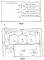
Figure 19 is a schematic diagram of access point coverage of the spread
spectrum cellular communication network in a parking lot 1200. As noted above, the
device's communication circuitry 118 utilizes the spread spectrum cellular
communication network for communicating with the host computer 1260. Access
points 1238, 1240 and 1242 represent interior access points of the network. Interior
access points have omni-directional antennas and therefore approximately circular areas
of communications coverage or cells. Access points 1244, 1246, 1248 and 1250 are
perimeter access points of the network. Each has a directed antenna for forming
coverage areas or cells as indicated by the two ellipses drawn around each of the
points.
The portable data collection device 10 mounted on the shopping cart 18 which
is pushed to a customer's car in the shopping parking lot 1200 may roam from cell to
cell and maintain radio contact with the host computer 1260, which also functions as
an access point and has a coverage area substantially equal to the boundaries of the
store 1202. Therefore, the device 10 provides an assistance call and anti-theft routine.
Figure 20 is a flowchart of the operation of the assistance call and anti-theft
subroutine. At step 1300, the subroutine monitors whether the assistance button 68 has
been depressed. If the button has be depressed, the device 10 emits aloud beeping
noise from the speaker 130 at step 1302 and store personnel are notified through a
message displayed on a visual display screen of the host computer 1260 at step 1304.
The message includes a location of which cell the cart 18 is in. Appropriate store
personnel can then assist the customer.
Alternatively, if at step 1300, the assistance button 68 is not depressed, the
subroutine, at step 1306, checks whether the cart 18 has been pushed out of range of
its current cell, if the cart 18 is out of its current cell, the subroutine determines, at step
1308, if it can reregister the devices communications circuitry 118 with another access
point. If the cart 18 has roamed out of range of the device's current cell and cannot
be reregistered with another access point, then the shopping cart 18 has left the bounds
of the store and the parking lot. At step 1310, the speaker 130 on the cart is
continuously sounded and a message is continuously flashed on the display screen 14
which requests that the cart 18 be returned to the store. At step 1314, an appropriate
message is displayed on the display screen of the host computer 1260 to alert store
personnel that the cart 18 has been taken from store property and providing information
setting forth the last cell the cart 18 was in.
An appropriate wireless local area network system including access points and
communications circuitry for the device is available from Aironet Wireless
Communications, Inc. of Akron, Ohio under the product name "Arlan System". Other
appropriate cellular network systems would be those complying with the draft IEEE
802.11 standard. Details of a spread spectrum cellular communications network are
set forth in U.S. Patent Application Serial No. 08/523,942, filed September 6, 1995,
and entitled CELLULAR COMMUNICATION SYSTEM WITH DYNAMICALLY
MODIFIED DATA TRANSMISSION PARAMETERS, the contents of which are
incorporated herein in the entirety by reference.
Figure 21 is an alternate embodiment of the portable data collection device of
the present invention. The device 1400 includes a housing 1410 which has an inverted
"L" shape in cross-section and is releasably mounted on a pushing handle 1416 of a
shopping cart 1414. A larger portion of the housing 1410 extends below the pushing
handle 1416 than the housing of the first embodiment. A similar clamping mechanism
as that disclosed in the first embodiment secures the housing to the cart handle 1416.
A battery (not shown) is supported in a casing on a lower rack of the cart powers the
device's electrical circuitry and modules as in the first embodiment.
The device 1400 includes electrical circuitry in the housing 1410 and a
retractable dataform reader 1422 which is similar to the circuitry described in
connection with the device 10 described in the first embodiment and includes a display
screen 1414 with an interactive touch sensitive overlay, similar to the display screen
14 in the first embodiment. The device 1400 further includes the retractable dataform
reader 1422, which is similar to the reader 22 described in the first embodiment and
includes a cable recoil mechanism which is similar to the cable recoil mechanism 138
described in the first embodiment. A front surface 1490 of the housing includes four
outer depressible buttons 1491, 1492, 1493, 1494 surrounding a central depressible
button 1495. The top and bottom buttons 1491, 1492 function as up and down
directional arrow keys when a highlight bar is displayed on the display screen 1414 and
the right and left buttons 1493, 1494 function as right and left directional arrow keys
when a cursor is displayed on the display screen.
Figure 22 is another alternate embodiment of the portable data collection device
of the present invention. The device 1500 includes a housing 1510 which is
"L" shaped in cross section and is releasably mounted on a pushing handle 1516 of a
shopping cart 1514. A larger portion of the housing 1510 extends below the pushing
handle 1516 than the housing of the first embodiment. A similar clamping mechanism
as that disclosed in the first embodiment secures the housing to the cart handle 1516.
A battery (not shown) is supported in a casing on a lower rack of the cart powers the
device's electrical circuitry and modules as in the first embodiment.
The device 1500 includes electrical circuitry disposed in the housing 1510 and
a retractable dataform reader 1422 which has electrical circuitry which is similar to the
electrical circuitry described in the first embodiment and includes a display screen 1514
with an interactive touch sensitive overlay, similar to the display screen 14 in the first
embodiment. The device 10 further includes the retractable dataform reader 1522,
which similar to the reader 22 described in the first embodiment and includes a cable
recoil mechanism similar to the cable recoil mechanism 138 described in the first
embodiment. A front surface 1590 of the housing includes a keypad 1591 comprising
a plurality of depressible keys. The keys of the keypad function to permit numeric
input to the device processor in lieu of the virtual numeric keypad display on the
display screen 14 set forth in the first embodiment.
While the present invention has been described with a degree of particularity,
it is the intent that the invention include all modifications and alterations from the
disclosed design falling within the spirit and scope of the appended claims.