EP1278096A2 - Liquid crystal display device - Google Patents
Liquid crystal display device Download PDFInfo
- Publication number
- EP1278096A2 EP1278096A2 EP02090249A EP02090249A EP1278096A2 EP 1278096 A2 EP1278096 A2 EP 1278096A2 EP 02090249 A EP02090249 A EP 02090249A EP 02090249 A EP02090249 A EP 02090249A EP 1278096 A2 EP1278096 A2 EP 1278096A2
- Authority
- EP
- European Patent Office
- Prior art keywords
- polarizer
- liquid crystal
- crystal display
- light
- reflection
- Prior art date
- Legal status (The legal status is an assumption and is not a legal conclusion. Google has not performed a legal analysis and makes no representation as to the accuracy of the status listed.)
- Withdrawn
Links
Images


Classifications
-
- G—PHYSICS
- G02—OPTICS
- G02F—OPTICAL DEVICES OR ARRANGEMENTS FOR THE CONTROL OF LIGHT BY MODIFICATION OF THE OPTICAL PROPERTIES OF THE MEDIA OF THE ELEMENTS INVOLVED THEREIN; NON-LINEAR OPTICS; FREQUENCY-CHANGING OF LIGHT; OPTICAL LOGIC ELEMENTS; OPTICAL ANALOGUE/DIGITAL CONVERTERS
- G02F1/00—Devices or arrangements for the control of the intensity, colour, phase, polarisation or direction of light arriving from an independent light source, e.g. switching, gating or modulating; Non-linear optics
- G02F1/01—Devices or arrangements for the control of the intensity, colour, phase, polarisation or direction of light arriving from an independent light source, e.g. switching, gating or modulating; Non-linear optics for the control of the intensity, phase, polarisation or colour
- G02F1/13—Devices or arrangements for the control of the intensity, colour, phase, polarisation or direction of light arriving from an independent light source, e.g. switching, gating or modulating; Non-linear optics for the control of the intensity, phase, polarisation or colour based on liquid crystals, e.g. single liquid crystal display cells
- G02F1/133—Constructional arrangements; Operation of liquid crystal cells; Circuit arrangements
- G02F1/1333—Constructional arrangements; Manufacturing methods
- G02F1/1335—Structural association of cells with optical devices, e.g. polarisers or reflectors
- G02F1/133528—Polarisers
- G02F1/133536—Reflective polarizers
-
- G—PHYSICS
- G02—OPTICS
- G02F—OPTICAL DEVICES OR ARRANGEMENTS FOR THE CONTROL OF LIGHT BY MODIFICATION OF THE OPTICAL PROPERTIES OF THE MEDIA OF THE ELEMENTS INVOLVED THEREIN; NON-LINEAR OPTICS; FREQUENCY-CHANGING OF LIGHT; OPTICAL LOGIC ELEMENTS; OPTICAL ANALOGUE/DIGITAL CONVERTERS
- G02F1/00—Devices or arrangements for the control of the intensity, colour, phase, polarisation or direction of light arriving from an independent light source, e.g. switching, gating or modulating; Non-linear optics
- G02F1/01—Devices or arrangements for the control of the intensity, colour, phase, polarisation or direction of light arriving from an independent light source, e.g. switching, gating or modulating; Non-linear optics for the control of the intensity, phase, polarisation or colour
- G02F1/13—Devices or arrangements for the control of the intensity, colour, phase, polarisation or direction of light arriving from an independent light source, e.g. switching, gating or modulating; Non-linear optics for the control of the intensity, phase, polarisation or colour based on liquid crystals, e.g. single liquid crystal display cells
- G02F1/133—Constructional arrangements; Operation of liquid crystal cells; Circuit arrangements
- G02F1/1333—Constructional arrangements; Manufacturing methods
- G02F1/1335—Structural association of cells with optical devices, e.g. polarisers or reflectors
- G02F1/133504—Diffusing, scattering, diffracting elements
Definitions
- the present invention relates to a liquid crystal display device, and more particularly to a liquid crystal display device in which utilization efficiency of external light can be improved when a display is used under a bright environment, such as sunlight, where there is a considerable amount of reflected and scattered ambient light.
- FIG. 1A is a cross sectional view of a conventional liquid crystal display device.
- a liquid crystal display unit 101 is composed of a liquid crystal cell 103, a polarizer 104 located on the front surface of the liquid crystal cell 103, a polarizer 105 located on the back surface of the liquid crystal cell 103 and a reflection polarizer 107 located on the back surface of the polarizer 105.
- the reflection polarizer 107 is located such that the transmission axis thereof is substantially aligned with that of the polarizer 105.
- the liquid crystal cell 103 is constructed so that a transparent electrode is provided on an inner surface of both or either of a pair of transparent substrates 108 and 109 which are bonded via a sealing agent 111 and a liquid crystal layer 110 is filled into a space surrounded by the transparent substrates 108, 109 and the sealing agent 111.
- a light irradiation unit 102 emits light to a back surface of the liquid crystal display unit 101.
- a transmission type liquid crystal display device having the light irradiation unit 102 provided on the back surface of such a liquid crystal display unit 101, visibility unfavorably becomes low when viewing images to be displayed under a bright environment, such as sunlight, where there is a considerable amount of reflected and scattered ambient light. This is because an external light is reflected from the surface of the liquid crystal display unit and its brightness cannot be ignored as compared with that of a light emitted from the light irradiation unit.
- an external light incident on the front surface of the liquid crystal display unit 101 transmits through the polarizer 104, the liquid crystal cell 103 and the polarizer 105 to the reflection polarizer 107.
- the external light since the direction of the transmission axis of the reflection polarizer 107 coincides with that of the polarizer 105, the external light transmits through the reflection polarizer 107 and is incident on the light irradiation unit 102 to be reflected by the surface of the light irradiation unit 102.
- the light irradiation unit 102 When a sheet having a high reflectance is provided on the light irradiation unit 102 to enhance the reflection of external light from the surface of the light irradiation unit 102 and to thereby utilize external light with high efficiency, light emitted from the light irradiation unit 102 is attenuated. Furthermore, since the reflection from the surface of the light irradiation unit 102 is mainly due to specular reflection, the brightness of the liquid crystal display unit in a direction perpendicular thereto is hard to increase.
- a primary object of the present invention is to provide a liquid crystal display device capable of utilizing external light with high efficiency while suppressing attenuation of a light emitted from a light irradiation unit, in which visibility becomes high when viewing images to be displayed under a bright environment, such as sunlight, where there is a considerable amount of reflected and scattered ambient light and brightness in a direction perpendicular to a liquid crystal display unit is enhanced.
- a liquid crystal display device includes two transparent substrates disposed to sandwich a liquid crystal therebetween, a front polarizer disposed on one of the two transparent substrates on a side thereof opposite the liquid crystal, a back polarizer disposed on the other of the two transparent substrates on a side thereof opposite the liquid crystal, a reflection polarizer disposed on the back polarizer on a side thereof opposite the other transparent substrate, and a light irradiation unit disposed on a side of the reflection polarizer opposite with respect to the other transparent substrate, in which the back polarizer and the reflection polarizer are disposed so as to make a geometric angle between a transmission axis of the back polarizer and a transmission axis of the reflection polarizer larger than 0° and equal to or smaller than 90°.
- the angle between the transmission axis of the back polarizer and that of the reflection polarizer is made larger than 0° and equal to or smaller than 90°. Accordingly, a part of external light incident on a liquid crystal display unit is reflected by the reflection polarizer and then dedicates itself to displaying images together with light emitted from the light irradiation unit to the back surface of the liquid crystal display unit, thereby achieving high brightness of images to be displayed.
- a liquid crystal display device includes two transparent substrates disposed to sandwich a liquid crystal therebetween, a front polarizer disposed on one of the two transparent substrates on a side thereof opposite the liquid crystal, a back polarizer disposed on the other of the two transparent substrates on a side thereof opposite the liquid crystal, a reflection polarizer disposed on the back polarizer on a side thereof opposite the other transparent substrate and a light irradiation unit disposed on a side of the reflection polarizer opposite with respect to the other transparent substrate, and is characterized in that the back polarizer and the reflection polarizer are bonded together through a diffusing adhesive material, which allows light transmitting therethrough to be diffused.
- the back polarizer and the reflection polarizer are bonded together using a diffusing adhesive material. Accordingly, external light incident on a liquid crystal display unit is not only emitted therefrom based on specular reflection, in other words, in a direction symmetrical to the direction in which external light enters but also emitted being diffused, thereby achieving high brightness of images to be displayed in a direction perpendicular to the liquid crystal display unit.
- a liquid crystal display device includes: two transparent substrates disposed to sandwich a liquid crystal therebetween, a front polarizer disposed on one of the two transparent substrates on a side thereof opposite the liquid crystal, a back polarizer disposed on the other of the two transparent substrates on a side thereof opposite the liquid crystal, a reflection polarizer disposed on the back polarizer on a side thereof opposite the other transparent substrate and a light irradiation unit disposed on a side of the reflection polarizer opposite with respect to the other transparent substrate, and is characterized in that the angle between the transmission axis of the back polarizer and that of the reflection polarizer is made larger than 0° and equal to or smaller than 90°, and the back polarizer and the reflection polarizer are bonded together through a diffusing adhesive material, which allows light transmitting therethrough to be diffused.
- external light incident on a liquid crystal display unit is not only emitted therefrom based on specular reflection, in other words, in a direction symmetrical to the direction in which the external light enters, but is also emitted being diffused by the diffusing adhesive material, thereby achieving high brightness of images to be displayed also in a direction perpendicular to the liquid crystal display unit.
- external light incident on the liquid crystal display unit is diffused by the diffusing adhesive material, external light incident on the reflection polarizer becomes light being diffused.
- the angle between the transmission axis of the back polarizer and that of the reflection polarizer is made larger than 0° and equal to or smaller than 90°, a part of the external light incident on the liquid crystal display unit is reflected by the reflection polarizer and then dedicates itself to displaying images together with light emitted from the light irradiation unit to the back surface of the liquid crystal display unit, thereby achieving high brightness of images to be displayed.
- a liquid crystal display device of an embodiment of the present invention will be described with reference to FIGS. 2A, 2B and 2C.
- FIG. 2A is a schematic cross sectional view in a situation where a liquid crystal display device of the present invention is cut across a plane that is perpendicular to a substrate.
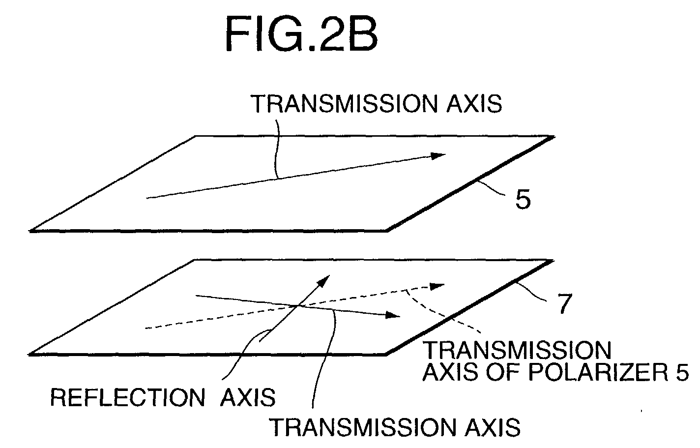
- FIG. 2B schematically shows a relationship between polarizing axes of two polarizers disposed on a substrate on a side thereof on which a light irradiation unit is located in the liquid crystal display device.
- FIG. 2C schematically shows a light irradiation unit.
- the liquid crystal display device includes a liquid crystal display unit 1 and a light irradiation unit 2, each being constructed as follows. Note that hereinafter, a side on which the light irradiation unit 2 is located with respect to the liquid crystal display unit 1 is called a back face and a side opposite the back surface with respect to the liquid crystal display unit 1 is called a front face.
- polarizers 4 and 5 are disposed on the front face and back face of a liquid crystal cell 3 on the front face and back face of a liquid crystal cell 3 on the front face and back face of a liquid crystal cell 3 on the front face and back face of a liquid crystal cell 3 on the front face and back face of a liquid crystal cell 3 on the front face and back face of a liquid crystal cell 3 on the front face and back face of a liquid crystal cell 3 on the front face and back face of a liquid crystal cell 3 are disposed on the front face and back face of a liquid crystal cell 3 on the front face and back face of a liquid crystal cell 3 on the front face and back face of a liquid crystal cell 3 are disposed on the front face and back face of a liquid crystal cell 3 on the front face and back face of a liquid crystal cell 3 on the front face and back face of a liquid crystal cell 3 are disposed on the front face and back face of a liquid crystal cell 3 on the front face and back face of a liquid crystal cell 3 on the front face and back face of a liquid
- a geometric angle between a transmission axis of the polarizer 5 and that of the reflection polarizer 7 is made ranging from 0° to 90° excluding 0°.
- the polarizer 5 and the reflection polarizer 7 are bonded together using a diffusing adhesive material 6 for diffusing light transmitting therethrough.
- These polarizers may be disposed via a diffusing sheet for diffusing light transmitting therethrough instead of the diffusing adhesive material.
- the diffusing adhesive material or the diffusion sheet serves to diffuse external light from the reflection polarizer 7 and increase a component of light emitted therefrom in a direction perpendicular to the liquid crystal display unit 1. Therefore, external light canbe effectively utilized by using only the conventional members without additional new members while dedicating itself to increasing brightness of images to be displayed in a direction perpendicular to the liquid crystal display unit.
- the present invention is characterized in that:
- the liquid crystal display unit 1 comprises the liquid crystal cell 3, the polarizer 4 disposed on the front face of the liquid crystal cell 3, the polarizer 5 disposed on the back face of the liquid crystal cell 3 and the reflection polarizer 7 bonded to the back face of the polarizer 5 through the diffusing adhesive material 6.
- the polarizer 4 is preferably processed such that the surface thereof is made to reflect light incident thereon to a reduced extent, which processing is typified such as by AR (anti-reflection) processing. As shown in FIG.
- the reflection polarizer 7 is characterized in that a transmission axis and a reflection axis thereof are substantially orthogonal to each other and the reflection polarizer allows light polarized along the transmission axis thereof to transmit therethrough and reflects light polarized along the reflection axis thereof.
- the polarizer 5 and the reflection polarizer 7 may be bonded together through the diffusing sheet instead of the diffusing adhesive material.
- a geometric size of the diffusing adhesive material or the diffusing sheet is generally represented by a Hayes ratio ((an amount of light transmitting through an associated material while being diffused)/(a total amount of light transmitting through the associated material) ⁇ 100).
- the Hayes ratio associated with the diffusing adhesive material or the diffusing sheet employed in the present invention is preferably made ranging from 0% to 100% excluding 0%, and more preferably ranging from 20% to 80%. The reason is as follows.
- the liquid crystal cell 3 is constructed so that a pair of transparent substrates 8, 9 are bonded together via a sealant 11, a transparent electrodeis disposed on an inner surface of one of the transparent substrates 8, 9, and a liquid crystal layer 10 is filled into a space enclosed by the transparent substrates 8, 9, and the sealant 11.
- the liquid crystal cell may be realized by employing a TN (twisted nematic) type, an IPS (inplane switching) type, a VA (vertical align) type or an OCB (optical compensated bend) type.
- FIG. 2C shows one embodiment of the light irradiation unit 2.
- the light irradiation unit 2 comprises an LED (light emitting diode) 12, a light guide plate 14, a light collection sheet 13 disposed on the light guide plate 14 and a reflection sheet 15 disposed under the light guide plate 14, and is configured to emit light to the back face of the liquid crystal display unit 1.
- LED light emitting diode
- the light irradiation unit 2 comprises an LED (light emitting diode) 12, a light guide plate 14, a light collection sheet 13 disposed on the light guide plate 14 and a reflection sheet 15 disposed under the light guide plate 14, and is configured to emit light to the back face of the liquid crystal display unit 1.
- the polarizer 5 and the reflection polarizer 7 are disposed such that the geometric angle between the transmission axes of those polarizers is made ranging from 0° to 90° excluding 0°.
- the liquid crystal display device When the angle between the transmission axis of the reflection polarizer 7 and that of the polarizer 5 becomes large, external light incident on the liquid crystal display unit 1 is reflected by the reflection polarizer 7 to a larger extent and as a result, the liquid crystal display device utilizes an external light with high efficiency. Contrary to it, light emitted from the light irradiation unit 2 is absorbed by the polarizer 5 to a larger extent and as a result, the liquid crystal display device utilizes light emitted from the light irradiation unit 2 with low efficiency. Accordingly, it can be concluded that the angle between the transmission axis of the reflection polarizer 7 and that of the polarizer 5 is preferably made ranging from 10° to 40°.
- External light incident on the liquid crystal display unit 1 moves as follows. That is, the light polarized along the axis perpendicular to the transmission axis of the polarizer 4 is absorbed by the polarizer 4 and the light polarized along the transmission axis of the polarizer 4 transmits through the polarizer 4 and is incident on the liquid crystal cell 3.
- the light incident on the liquid crystal cell is polarized depending on an alignment state of a liquid crystal molecule, which changes in accordance with a voltage applied to the transparent electrodes and then is incident on the polarizer 5.
- the light incident on the polarizer 5 moves such that the light polarized along the axis perpendicular to the transmission axis of the polarizer 5 is absorbed by the polarizer 5 and the light polarized along the transmission axis of the polarizer 5 transmits through the polarizer 5 and is incident on the liquid crystal cell 3.
- the reflection polarizer 7 and the polarizer 5 are bonded together via the diffusing adhesive material 6, and therefore, light transmitted through the polarizer 5 is diffused by the diffusing adhesive material 6 and is incident on the reflection polarizer 7. Since the angle between the transmission axis of the polarizer 5 and that of the reflection polarizer 7 is made ranging from 0° to 90° excluding 0°, light transmitting through the polarizer 5 includes two components, i.
- the liquid crystal display device of the present invention a part of external light incident on the liquid crystal display unit 1 is reflected by the reflection polarizer dedicated to displaying images in corporation with light emitted from the light irradiation unit to the back surface of the liquid crystal display unit, thereby achieving high brightness of images to be displayed.
- employing the diffusing adhesive material makes an external light incident on the liquid crystal display unit not only emitted in accordance with specular reflection direction, in other words, in a direction symmetrical to the direction in which the external light enters, but also emitted while being diffused, thereby achieving high brightness of images to be displayed in a direction perpendicular to the liquid crystal display unit.
Abstract

Description
- The present invention relates to a liquid crystal display device, and more particularly to a liquid crystal display device in which utilization efficiency of external light can be improved when a display is used under a bright environment, such as sunlight, where there is a considerable amount of reflected and scattered ambient light.
- FIG. 1A is a cross sectional view of a conventional liquid crystal display device. A liquid
crystal display unit 101 is composed of aliquid crystal cell 103, apolarizer 104 located on the front surface of theliquid crystal cell 103, apolarizer 105 located on the back surface of theliquid crystal cell 103 and areflection polarizer 107 located on the back surface of thepolarizer 105. As shown in FIG. 1B, thereflection polarizer 107 is located such that the transmission axis thereof is substantially aligned with that of thepolarizer 105. - The
liquid crystal cell 103 is constructed so that a transparent electrode is provided on an inner surface of both or either of a pair oftransparent substrates sealing agent 111 and aliquid crystal layer 110 is filled into a space surrounded by thetransparent substrates sealing agent 111. Alight irradiation unit 102 emits light to a back surface of the liquidcrystal display unit 101. - In a transmission type liquid crystal display device having the
light irradiation unit 102 provided on the back surface of such a liquidcrystal display unit 101, visibility unfavorably becomes low when viewing images to be displayed under a bright environment, such as sunlight, where there is a considerable amount of reflected and scattered ambient light. This is because an external light is reflected from the surface of the liquid crystal display unit and its brightness cannot be ignored as compared with that of a light emitted from the light irradiation unit. - In order to reduce an amount of an external light reflected by the surface of the liquid crystal display unit, AR (anti-reflection) processing or the like is performed with respect to the surface of the
polarizer 104, which operation is not sufficient to reduce an amount of the reflected external light. Thus, it is required to effectively utilize an external light to obtain high brightness such that the eternal light is reflected from the inner portion of the liquid crystal display device and used for display together with a light emitted from the light irradiation unit. - However, in the above-described conventional example, an external light incident on the front surface of the liquid
crystal display unit 101 transmits through thepolarizer 104, theliquid crystal cell 103 and thepolarizer 105 to thereflection polarizer 107. In this case, since the direction of the transmission axis of thereflection polarizer 107 coincides with that of thepolarizer 105, the external light transmits through thereflection polarizer 107 and is incident on thelight irradiation unit 102 to be reflected by the surface of thelight irradiation unit 102. When a sheet having a high reflectance is provided on thelight irradiation unit 102 to enhance the reflection of external light from the surface of thelight irradiation unit 102 and to thereby utilize external light with high efficiency, light emitted from thelight irradiation unit 102 is attenuated. Furthermore, since the reflection from the surface of thelight irradiation unit 102 is mainly due to specular reflection, the brightness of the liquid crystal display unit in a direction perpendicular thereto is hard to increase. - A primary object of the present invention is to provide a liquid crystal display device capable of utilizing external light with high efficiency while suppressing attenuation of a light emitted from a light irradiation unit, in which visibility becomes high when viewing images to be displayed under a bright environment, such as sunlight, where there is a considerable amount of reflected and scattered ambient light and brightness in a direction perpendicular to a liquid crystal display unit is enhanced.
- A liquid crystal display device according to a first aspect of the present invention includes two transparent substrates disposed to sandwich a liquid crystal therebetween, a front polarizer disposed on one of the two transparent substrates on a side thereof opposite the liquid crystal, a back polarizer disposed on the other of the two transparent substrates on a side thereof opposite the liquid crystal, a reflection polarizer disposed on the back polarizer on a side thereof opposite the other transparent substrate, and a light irradiation unit disposed on a side of the reflection polarizer opposite with respect to the other transparent substrate, in which the back polarizer and the reflection polarizer are disposed so as to make a geometric angle between a transmission axis of the back polarizer and a transmission axis of the reflection polarizer larger than 0° and equal to or smaller than 90°.
- According to the liquid crystal display device of the first aspect of the invention, the angle between the transmission axis of the back polarizer and that of the reflection polarizer is made larger than 0° and equal to or smaller than 90°. Accordingly, a part of external light incident on a liquid crystal display unit is reflected by the reflection polarizer and then dedicates itself to displaying images together with light emitted from the light irradiation unit to the back surface of the liquid crystal display unit, thereby achieving high brightness of images to be displayed.
- A liquid crystal display device according to a second aspect of the present invention includes two transparent substrates disposed to sandwich a liquid crystal therebetween, a front polarizer disposed on one of the two transparent substrates on a side thereof opposite the liquid crystal, a back polarizer disposed on the other of the two transparent substrates on a side thereof opposite the liquid crystal, a reflection polarizer disposed on the back polarizer on a side thereof opposite the other transparent substrate and a light irradiation unit disposed on a side of the reflection polarizer opposite with respect to the other transparent substrate, and is characterized in that the back polarizer and the reflection polarizer are bonded together through a diffusing adhesive material, which allows light transmitting therethrough to be diffused.
- According to the liquid crystal display device of the second aspect of the invention, the back polarizer and the reflection polarizer are bonded together using a diffusing adhesive material. Accordingly, external light incident on a liquid crystal display unit is not only emitted therefrom based on specular reflection, in other words, in a direction symmetrical to the direction in which external light enters but also emitted being diffused, thereby achieving high brightness of images to be displayed in a direction perpendicular to the liquid crystal display unit.
- A liquid crystal display device according to a third aspect of the present invention includes: two transparent substrates disposed to sandwich a liquid crystal therebetween, a front polarizer disposed on one of the two transparent substrates on a side thereof opposite the liquid crystal, a back polarizer disposed on the other of the two transparent substrates on a side thereof opposite the liquid crystal, a reflection polarizer disposed on the back polarizer on a side thereof opposite the other transparent substrate and a light irradiation unit disposed on a side of the reflection polarizer opposite with respect to the other transparent substrate, and is characterized in that the angle between the transmission axis of the back polarizer and that of the reflection polarizer is made larger than 0° and equal to or smaller than 90°, and the back polarizer and the reflection polarizer are bonded together through a diffusing adhesive material, which allows light transmitting therethrough to be diffused.
- According to the liquid crystal display device of the third aspect of the invention, external light incident on a liquid crystal display unit is not only emitted therefrom based on specular reflection, in other words, in a direction symmetrical to the direction in which the external light enters, but is also emitted being diffused by the diffusing adhesive material, thereby achieving high brightness of images to be displayed also in a direction perpendicular to the liquid crystal display unit. In addition, when external light incident on the liquid crystal display unit is diffused by the diffusing adhesive material, external light incident on the reflection polarizer becomes light being diffused. Furthermore, since the angle between the transmission axis of the back polarizer and that of the reflection polarizer is made larger than 0° and equal to or smaller than 90°, a part of the external light incident on the liquid crystal display unit is reflected by the reflection polarizer and then dedicates itself to displaying images together with light emitted from the light irradiation unit to the back surface of the liquid crystal display unit, thereby achieving high brightness of images to be displayed.
-
- FIG. 1A is a schematic cross sectional view of a conventional liquid crystal display device;
- FIG. 1B is a schematic view indicating the relationship between transmission/reflection axes of one polarizer and transmission/reflection axes of the other;
- FIG. 2A is a schematic cross sectional view of a liquid crystal display device according to an embodiment of the present invention;
- FIG. 2B is a schematic view indicating the relationship between polarizing axes of two polarizers in the liquid crystal display device; and
- FIG. 2C is a schematic cross sectional view showing a structure of a light irradiation unit in the liquid crystal display device.
-
- A liquid crystal display device of an embodiment of the present invention will be described with reference to FIGS. 2A, 2B and 2C.
- FIG. 2A is a schematic cross sectional view in a situation where a liquid crystal display device of the present invention is cut across a plane that is perpendicular to a substrate. FIG. 2B schematically shows a relationship between polarizing axes of two polarizers disposed on a substrate on a side thereof on which a light irradiation unit is located in the liquid crystal display device. FIG. 2C schematically shows a light irradiation unit. The liquid crystal display device includes a liquid
crystal display unit 1 and alight irradiation unit 2, each being constructed as follows. Note that hereinafter, a side on which thelight irradiation unit 2 is located with respect to the liquidcrystal display unit 1 is called a back face and a side opposite the back surface with respect to the liquidcrystal display unit 1 is called a front face. - First, as shown in FIG. 2A, on the front face and back face of a
liquid crystal cell 3 are disposedpolarizers reflection polarizer 7 is disposed on the back face of thepolarizer 5. On the side of the back face of the liquid crystal display unit 1thelight irradiation unit 2 is disposed for emitting light to the liquidcrystal display unit 1. - As shown in FIG. 2B, a geometric angle between a transmission axis of the
polarizer 5 and that of thereflection polarizer 7 is made ranging from 0° to 90° excluding 0°. In addition, thepolarizer 5 and thereflection polarizer 7 are bonded together using a diffusingadhesive material 6 for diffusing light transmitting therethrough. These polarizers may be disposed via a diffusing sheet for diffusing light transmitting therethrough instead of the diffusing adhesive material. - Since the transmission axis of the
polarizer 5 and that of thereflection polarizer 7 are not made in parallel with each other, a polarizing component along the reflection axis of thereflection polarizer 7 is present in the external light that transmits through the front face of the liquidcrystal display unit 1, thepolarizer 4, theliquid crystal cell 3 and thepolarizer 5 in this order to thereflection polarizer 7. Thus, external light is reflected from thereflection polarizer 7 and emitted to the front face of the liquidcrystal display unit 1. Therefore, external light canbe utilized effectively. The diffusing adhesive material or the diffusion sheet serves to diffuse external light from thereflection polarizer 7 and increase a component of light emitted therefrom in a direction perpendicular to the liquidcrystal display unit 1. Therefore, external light canbe effectively utilized by using only the conventional members without additional new members while dedicating itself to increasing brightness of images to be displayed in a direction perpendicular to the liquid crystal display unit. - As described above, the present invention is characterized in that:
- (1) the geometric angle between the transmission axis of the polarizer disposed on the back face of the liquid crystal cell and that of the reflection polarizer disposed on the back face of the polarizer is made ranging from 0° to 90° excluding 0°;
- (2) the polarizer disposed on the back face of the liquid crystal cell and the reflection polarizer disposed on the back face of the polarizer are bonded together using the diffusing adhesive material for diffusing light transmitting therethrough or disposed through the diffusing sheet for diffusing light transmitting therethrough; and
- (3) the geometric angle between the transmission axis of the polarizer disposed on the back face of the liquid crystal cell and that of the reflection polarizer disposed on the back face of the polarizer is made ranging from 0° to 90° excluding 0°, and the polarizer and the reflection polarizer are bonded together using the diffusing adhesive material for diffusing a light transmitting therethrough, or disposed via the diffusing sheet for diffusing light transmitting therethrough.
-
- The present invention will be described in more detail in the following.
- As shown in FIG. 2A, the liquid
crystal display unit 1 comprises theliquid crystal cell 3, thepolarizer 4 disposed on the front face of theliquid crystal cell 3, thepolarizer 5 disposed on the back face of theliquid crystal cell 3 and thereflection polarizer 7 bonded to the back face of thepolarizer 5 through the diffusingadhesive material 6. Thepolarizer 4 is preferably processed such that the surface thereof is made to reflect light incident thereon to a reduced extent, which processing is typified such as by AR (anti-reflection) processing. As shown in FIG. 2B, thereflection polarizer 7 is characterized in that a transmission axis and a reflection axis thereof are substantially orthogonal to each other and the reflection polarizer allows light polarized along the transmission axis thereof to transmit therethrough and reflects light polarized along the reflection axis thereof. Thepolarizer 5 and thereflection polarizer 7 may be bonded together through the diffusing sheet instead of the diffusing adhesive material. - A geometric size of the diffusing adhesive material or the diffusing sheet is generally represented by a Hayes ratio ((an amount of light transmitting through an associated material while being diffused)/(a total amount of light transmitting through the associated material) × 100). The Hayes ratio associated with the diffusing adhesive material or the diffusing sheet employed in the present invention is preferably made ranging from 0% to 100% excluding 0%, and more preferably ranging from 20% to 80%. The reason is as follows. That is, when the Hayes ratio is high, light emitted from the
light irradiation unit 2 is diffused to reduce the brightness at the surface of the liquidcrystal display unit 1 and when the Hayes ratio is low, external light reflected from thereflection polarizer 7 is diffused to a reduced extent, thereby preventing the liquid crystal display device from increasing brightness in a direction perpendicular to liquidcrystal display unit 1. - The
liquid crystal cell 3 is constructed so that a pair oftransparent substrates sealant 11, a transparent electrodeis disposed on an inner surface of one of thetransparent substrates liquid crystal layer 10 is filled into a space enclosed by thetransparent substrates sealant 11. The liquid crystal cell may be realized by employing a TN (twisted nematic) type, an IPS (inplane switching) type, a VA (vertical align) type or an OCB (optical compensated bend) type. - FIG. 2C shows one embodiment of the
light irradiation unit 2. Thelight irradiation unit 2 comprises an LED (light emitting diode) 12, a light guide plate 14, alight collection sheet 13 disposed on the light guide plate 14 and areflection sheet 15 disposed under the light guide plate 14, and is configured to emit light to the back face of the liquidcrystal display unit 1. - According to the present invention, as shown in FIG. 2B, the
polarizer 5 and thereflection polarizer 7 are disposed such that the geometric angle between the transmission axes of those polarizers is made ranging from 0° to 90° excluding 0°. - When the angle between the transmission axis of the
reflection polarizer 7 and that of thepolarizer 5 becomes large, external light incident on the liquidcrystal display unit 1 is reflected by thereflection polarizer 7 to a larger extent and as a result, the liquid crystal display device utilizes an external light with high efficiency. Contrary to it, light emitted from thelight irradiation unit 2 is absorbed by thepolarizer 5 to a larger extent and as a result, the liquid crystal display device utilizes light emitted from thelight irradiation unit 2 with low efficiency. Accordingly, it can be concluded that the angle between the transmission axis of thereflection polarizer 7 and that of thepolarizer 5 is preferably made ranging from 10° to 40°. - External light incident on the liquid
crystal display unit 1 moves as follows. That is, the light polarized along the axis perpendicular to the transmission axis of thepolarizer 4 is absorbed by thepolarizer 4 and the light polarized along the transmission axis of thepolarizer 4 transmits through thepolarizer 4 and is incident on theliquid crystal cell 3. The light incident on the liquid crystal cell is polarized depending on an alignment state of a liquid crystal molecule, which changes in accordance with a voltage applied to the transparent electrodes and then is incident on thepolarizer 5. The light incident on thepolarizer 5 moves such that the light polarized along the axis perpendicular to the transmission axis of thepolarizer 5 is absorbed by thepolarizer 5 and the light polarized along the transmission axis of thepolarizer 5 transmits through thepolarizer 5 and is incident on theliquid crystal cell 3. - According to the construction of this embodiment, the
reflection polarizer 7 and thepolarizer 5 are bonded together via the diffusingadhesive material 6, and therefore, light transmitted through thepolarizer 5 is diffused by the diffusingadhesive material 6 and is incident on thereflection polarizer 7. Since the angle between the transmission axis of thepolarizer 5 and that of thereflection polarizer 7 is made ranging from 0° to 90° excluding 0°, light transmitting through thepolarizer 5 includes two components, i. e., light polarized along the transmission axis of thepolarizer 7 and light polarized along the axis reflection axis (perpendicular to the transmission axis) of thepolarizer 7, and the former transmits through thepolarizer 7 and then is incident on the light irradiation unit, and the latter is reflected by thepolarizer 7 and diffused by the diffusingadhesive material 6 and then is incident on thepolarizer 5. - According to the liquid crystal display device of the present invention, a part of external light incident on the liquid
crystal display unit 1 is reflected by the reflection polarizer dedicated to displaying images in corporation with light emitted from the light irradiation unit to the back surface of the liquid crystal display unit, thereby achieving high brightness of images to be displayed. In addition, employing the diffusing adhesive material makes an external light incident on the liquid crystal display unit not only emitted in accordance with specular reflection direction, in other words, in a direction symmetrical to the direction in which the external light enters, but also emitted while being diffused, thereby achieving high brightness of images to be displayed in a direction perpendicular to the liquid crystal display unit.
Claims (6)
- A liquid crystal display device comprising:two transparent substrates disposed to sandwich a liquid crystal therebetween;a front polarizer disposed on one of said two transparent substrates on a side thereof opposite said liquid crystal;a back polarizer disposed on the other of said two transparent substrates on a side thereof opposite said liquid crystal;a reflection polarizer disposed on said back polarizer on a side thereof opposite the other of said two transparent substrates; anda light irradiation unit disposed on a side of said reflection polarizer opposite with respect to the other of said two transparent substrates,said back polarizer and said reflection polarizer being disposed so as to make a geometric angle between a transmission axis of said back polarizer and a transmission axis of said reflection polarizer larger than 0° and equal to or smaller than 90°.
- The liquid crystal display device according to claim 1, wherein said back polarizer and said reflection polarizer are bonded together via an adhesive material for diffusing light transmitting therethrough.
- The liquid crystal display device according to claim 1, wherein the geometric angle between the transmission axis of said back polarizer and the transmission axis of said reflection polarizer is made ranging from 10° to 40°.
- The liquid crystal display device according to claim 2, wherein said adhesive material for diffusing light transmitting therethrough serves to make said light move in accordance with a formula represented by 0 < (an amount of a light transmitting through said adhesive material while being diffused)/(a total amount of a light transmitting through said adhesive material) × 100 □ 100.
- A liquid crystal display device according to claim 4, wherein said adhesive material for diffusing a light transmitting therethrough serves to make said light move in accordance with a formula 20 □ (an amount of a light transmitting through said adhesive material while being diffused)/(a total amount of a light transmitting through said adhesive material) × 100 □ 80.
- The liquid crystal display device according to claim 1, wherein said light irradiation unit is formed such that a light collection sheet, a light guide plate and a reflection sheet are disposed in order in a direction departing from said reflection polarizer for said light irradiation unit and is configured to introduce a light into said light guide plate and then emit light to said reflection polarizer.
Applications Claiming Priority (2)
| Application Number | Priority Date | Filing Date | Title |
|---|---|---|---|
| JP2001214937 | 2001-07-16 | ||
| JP2001214937A JP2003029251A (en) | 2001-07-16 | 2001-07-16 | Liquid crystal display device |
Publications (2)
| Publication Number | Publication Date |
|---|---|
| EP1278096A2 true EP1278096A2 (en) | 2003-01-22 |
| EP1278096A3 EP1278096A3 (en) | 2003-12-17 |
Family
ID=19049668
Family Applications (1)
| Application Number | Title | Priority Date | Filing Date |
|---|---|---|---|
| EP02090249A Withdrawn EP1278096A3 (en) | 2001-07-16 | 2002-07-12 | Liquid crystal display device |
Country Status (7)
| Country | Link |
|---|---|
| US (1) | US20030011726A1 (en) |
| EP (1) | EP1278096A3 (en) |
| JP (1) | JP2003029251A (en) |
| KR (1) | KR20030007217A (en) |
| CN (1) | CN1185526C (en) |
| NO (1) | NO20023391L (en) |
| TW (1) | TW588194B (en) |
Families Citing this family (5)
| Publication number | Priority date | Publication date | Assignee | Title |
|---|---|---|---|---|
| JP2001215333A (en) * | 2000-02-07 | 2001-08-10 | Sumitomo Chem Co Ltd | Semitransmissive semireflective polarizing element |
| WO2005008322A1 (en) * | 2003-07-23 | 2005-01-27 | Sharp Kabushiki Kaisha | Liquid crystal display unit |
| KR20090080370A (en) * | 2008-01-21 | 2009-07-24 | 삼성전자주식회사 | Polarizer and display device having the same |
| CN105278154A (en) * | 2015-11-25 | 2016-01-27 | 武汉华星光电技术有限公司 | Liquid crystal display device and liquid crystal display panel thereof |
| JP6950139B2 (en) * | 2017-04-25 | 2021-10-13 | エルジー・ケム・リミテッド | Optical device |
Citations (3)
| Publication number | Priority date | Publication date | Assignee | Title |
|---|---|---|---|---|
| WO1997001788A1 (en) * | 1995-06-26 | 1997-01-16 | Minnesota Mining And Manufacturing Company | Transflective displays with reflective polarizing transflector |
| US5686979A (en) * | 1995-06-26 | 1997-11-11 | Minnesota Mining And Manufacturing Company | Optical panel capable of switching between reflective and transmissive states |
| WO2001027528A1 (en) * | 1999-10-08 | 2001-04-19 | 3M Innovative Properties Company | Display illumination device and method of enhancing brightness in a display illumination device |
Family Cites Families (9)
| Publication number | Priority date | Publication date | Assignee | Title |
|---|---|---|---|---|
| KR100505522B1 (en) * | 1997-07-25 | 2005-08-04 | 세이코 엡슨 가부시키가이샤 | Display and electronic device equipped with the same |
| JP3874224B2 (en) * | 1997-09-12 | 2007-01-31 | インターナショナル・ビジネス・マシーンズ・コーポレーション | Light guide unit and liquid crystal display device for increasing polarization component |
| JPH11316372A (en) * | 1998-04-30 | 1999-11-16 | Seiko Epson Corp | Liquid crystal device and electronic equipment |
| US6285426B1 (en) * | 1998-07-06 | 2001-09-04 | Motorola, Inc. | Ridged reflector having optically transmissive properties for an optical display device |
| JP3839998B2 (en) * | 1998-10-28 | 2006-11-01 | シャープ株式会社 | Backlight |
| EP1152282A4 (en) * | 1998-12-09 | 2005-03-02 | Citizen Watch Co Ltd | Liquid-crystal display device |
| US6630968B1 (en) * | 1999-02-01 | 2003-10-07 | Seiko Epson Corporation | Display device, electronic apparatus using the same, and light guider for display devices |
| JP3747751B2 (en) * | 1999-09-30 | 2006-02-22 | カシオ計算機株式会社 | Liquid crystal display |
| JP2001183651A (en) * | 1999-10-13 | 2001-07-06 | Citizen Watch Co Ltd | Color liquid crystal display device |
-
2001
- 2001-07-16 JP JP2001214937A patent/JP2003029251A/en active Pending
-
2002
- 2002-07-11 TW TW091115644A patent/TW588194B/en not_active IP Right Cessation
- 2002-07-12 EP EP02090249A patent/EP1278096A3/en not_active Withdrawn
- 2002-07-12 US US10/193,164 patent/US20030011726A1/en not_active Abandoned
- 2002-07-12 NO NO20023391A patent/NO20023391L/en not_active Application Discontinuation
- 2002-07-16 KR KR1020020041708A patent/KR20030007217A/en not_active Application Discontinuation
- 2002-07-16 CN CNB021410909A patent/CN1185526C/en not_active Expired - Lifetime
Patent Citations (3)
| Publication number | Priority date | Publication date | Assignee | Title |
|---|---|---|---|---|
| WO1997001788A1 (en) * | 1995-06-26 | 1997-01-16 | Minnesota Mining And Manufacturing Company | Transflective displays with reflective polarizing transflector |
| US5686979A (en) * | 1995-06-26 | 1997-11-11 | Minnesota Mining And Manufacturing Company | Optical panel capable of switching between reflective and transmissive states |
| WO2001027528A1 (en) * | 1999-10-08 | 2001-04-19 | 3M Innovative Properties Company | Display illumination device and method of enhancing brightness in a display illumination device |
Also Published As
| Publication number | Publication date |
|---|---|
| CN1185526C (en) | 2005-01-19 |
| CN1397825A (en) | 2003-02-19 |
| US20030011726A1 (en) | 2003-01-16 |
| TW588194B (en) | 2004-05-21 |
| NO20023391L (en) | 2003-01-17 |
| KR20030007217A (en) | 2003-01-23 |
| JP2003029251A (en) | 2003-01-29 |
| EP1278096A3 (en) | 2003-12-17 |
| NO20023391D0 (en) | 2002-07-12 |
Similar Documents
| Publication | Publication Date | Title |
|---|---|---|
| KR200332340Y1 (en) | Liquid crystal display device and electronic apparatus | |
| US6597418B2 (en) | Transparent reflective liquid crystal display | |
| JP3849249B2 (en) | Liquid crystal display | |
| KR100733643B1 (en) | Passive transflective assembly, passive polarizer assembly and optical system | |
| TWI242664B (en) | Display device | |
| US8107025B2 (en) | Display unit having illuminator and liquid crystal layer capable of forming intermediate layer | |
| TW200407601A (en) | Surface light source emitt light from both surfaces, and double side display using the same | |
| US10613371B2 (en) | Liquid crystal display device | |
| KR101101427B1 (en) | Liquid crystal display apparatus | |
| JP2002287132A (en) | Liquid crystal display device and electronic apparatus | |
| KR100945359B1 (en) | Liquid crystal display device | |
| KR20040031858A (en) | Liquid crystal display | |
| JP2000122046A (en) | Liquid crystal display device | |
| EP1278096A2 (en) | Liquid crystal display device | |
| JP2002098960A (en) | Display device | |
| US20130258710A1 (en) | Slim Frame Backlight Module | |
| JP2001215505A (en) | Liquid crystal display device and mobile information terminal device | |
| JP2006350873A (en) | Display device | |
| JPWO2011083720A1 (en) | Liquid crystal display | |
| JPH11133419A (en) | Liquid crystal display device | |
| JP5454443B2 (en) | Liquid crystal display | |
| JP2020112729A (en) | Liquid crystal display device | |
| JP4813705B2 (en) | Liquid crystal display | |
| KR100905329B1 (en) | Backlight assembly | |
| KR20010056033A (en) | Semipermeable LCD |
Legal Events
| Date | Code | Title | Description |
|---|---|---|---|
| PUAI | Public reference made under article 153(3) epc to a published international application that has entered the european phase |
Free format text: ORIGINAL CODE: 0009012 |
|
| AK | Designated contracting states |
Kind code of ref document: A2 Designated state(s): AT BE BG CH CY CZ DE DK EE ES FI FR GB GR IE IT LI LU MC NL PT SE SK TR |
|
| AX | Request for extension of the european patent |
Free format text: AL;LT;LV;MK;RO;SI |
|
| RAP1 | Party data changed (applicant data changed or rights of an application transferred) |
Owner name: NEC LCD TECHNOLOGIES, LTD. |
|
| PUAL | Search report despatched |
Free format text: ORIGINAL CODE: 0009013 |
|
| AK | Designated contracting states |
Kind code of ref document: A3 Designated state(s): AT BE BG CH CY CZ DE DK EE ES FI FR GB GR IE IT LI LU MC NL PT SE SK TR |
|
| AX | Request for extension of the european patent |
Extension state: AL LT LV MK RO SI |
|
| 17P | Request for examination filed |
Effective date: 20040112 |
|
| AKX | Designation fees paid |
Designated state(s): DE FI FR GB NL |
|
| STAA | Information on the status of an ep patent application or granted ep patent |
Free format text: STATUS: THE APPLICATION HAS BEEN WITHDRAWN |
|
| 18W | Application withdrawn |
Effective date: 20080320 |