EP1278095A1 - Rimless spectacles - Google Patents
Rimless spectacles Download PDFInfo
- Publication number
- EP1278095A1 EP1278095A1 EP01921953A EP01921953A EP1278095A1 EP 1278095 A1 EP1278095 A1 EP 1278095A1 EP 01921953 A EP01921953 A EP 01921953A EP 01921953 A EP01921953 A EP 01921953A EP 1278095 A1 EP1278095 A1 EP 1278095A1
- Authority
- EP
- European Patent Office
- Prior art keywords
- cutouts
- attachment members
- spectacle lenses
- attachment
- attached
- Prior art date
- Legal status (The legal status is an assumption and is not a legal conclusion. Google has not performed a legal analysis and makes no representation as to the accuracy of the status listed.)
- Granted
Links
Images







Classifications
-
- G—PHYSICS
- G02—OPTICS
- G02C—SPECTACLES; SUNGLASSES OR GOGGLES INSOFAR AS THEY HAVE THE SAME FEATURES AS SPECTACLES; CONTACT LENSES
- G02C1/00—Assemblies of lenses with bridges or browbars
- G02C1/02—Bridge or browbar secured to lenses without the use of rims
- G02C1/023—Bridge or browbar secured to lenses without the use of rims with lenses secured to the fixing parts by clamping, luting, soldering, gluing without holes or recesses in the lenses
-
- B—PERFORMING OPERATIONS; TRANSPORTING
- B24—GRINDING; POLISHING
- B24B—MACHINES, DEVICES, OR PROCESSES FOR GRINDING OR POLISHING; DRESSING OR CONDITIONING OF ABRADING SURFACES; FEEDING OF GRINDING, POLISHING, OR LAPPING AGENTS
- B24B47/00—Drives or gearings; Equipment therefor
- B24B47/22—Equipment for exact control of the position of the grinding tool or work at the start of the grinding operation
- B24B47/225—Equipment for exact control of the position of the grinding tool or work at the start of the grinding operation for bevelling optical work, e.g. lenses
-
- B—PERFORMING OPERATIONS; TRANSPORTING
- B24—GRINDING; POLISHING
- B24B—MACHINES, DEVICES, OR PROCESSES FOR GRINDING OR POLISHING; DRESSING OR CONDITIONING OF ABRADING SURFACES; FEEDING OF GRINDING, POLISHING, OR LAPPING AGENTS
- B24B9/00—Machines or devices designed for grinding edges or bevels on work or for removing burrs; Accessories therefor
- B24B9/02—Machines or devices designed for grinding edges or bevels on work or for removing burrs; Accessories therefor characterised by a special design with respect to properties of materials specific to articles to be ground
- B24B9/06—Machines or devices designed for grinding edges or bevels on work or for removing burrs; Accessories therefor characterised by a special design with respect to properties of materials specific to articles to be ground of non-metallic inorganic material, e.g. stone, ceramics, porcelain
- B24B9/08—Machines or devices designed for grinding edges or bevels on work or for removing burrs; Accessories therefor characterised by a special design with respect to properties of materials specific to articles to be ground of non-metallic inorganic material, e.g. stone, ceramics, porcelain of glass
- B24B9/14—Machines or devices designed for grinding edges or bevels on work or for removing burrs; Accessories therefor characterised by a special design with respect to properties of materials specific to articles to be ground of non-metallic inorganic material, e.g. stone, ceramics, porcelain of glass of optical work, e.g. lenses, prisms
-
- B—PERFORMING OPERATIONS; TRANSPORTING
- B24—GRINDING; POLISHING
- B24B—MACHINES, DEVICES, OR PROCESSES FOR GRINDING OR POLISHING; DRESSING OR CONDITIONING OF ABRADING SURFACES; FEEDING OF GRINDING, POLISHING, OR LAPPING AGENTS
- B24B9/00—Machines or devices designed for grinding edges or bevels on work or for removing burrs; Accessories therefor
- B24B9/02—Machines or devices designed for grinding edges or bevels on work or for removing burrs; Accessories therefor characterised by a special design with respect to properties of materials specific to articles to be ground
- B24B9/06—Machines or devices designed for grinding edges or bevels on work or for removing burrs; Accessories therefor characterised by a special design with respect to properties of materials specific to articles to be ground of non-metallic inorganic material, e.g. stone, ceramics, porcelain
- B24B9/08—Machines or devices designed for grinding edges or bevels on work or for removing burrs; Accessories therefor characterised by a special design with respect to properties of materials specific to articles to be ground of non-metallic inorganic material, e.g. stone, ceramics, porcelain of glass
- B24B9/14—Machines or devices designed for grinding edges or bevels on work or for removing burrs; Accessories therefor characterised by a special design with respect to properties of materials specific to articles to be ground of non-metallic inorganic material, e.g. stone, ceramics, porcelain of glass of optical work, e.g. lenses, prisms
- B24B9/146—Accessories, e.g. lens mounting devices
-
- G—PHYSICS
- G02—OPTICS
- G02C—SPECTACLES; SUNGLASSES OR GOGGLES INSOFAR AS THEY HAVE THE SAME FEATURES AS SPECTACLES; CONTACT LENSES
- G02C1/00—Assemblies of lenses with bridges or browbars
- G02C1/02—Bridge or browbar secured to lenses without the use of rims
Definitions
- This invention relates to rimless spectacles wherein cutouts or the like are provided at the edges of the spectacle lenses and attachment members are attached to those cutouts or the like without using rims.
- rimless spectacles Attention has been drawn in recent years to a rimless type of spectacles (rimless spectacles) because they offer such advantages as a wide field of view and light weight.
- rimless spectacles There are several types of such rimless spectacles, namely a type wherewith the lower circumference of the lens is suspended by a nylon thread, a type wherewith holes for machine screws are made all the way through the lenses and the frame is secured by machine screws passed through these holes (called two-point or three-piece type), and the PinFeel type wherewith holes are made in the lens edge surfaces, but not all the way through, and pin-like projections in spectacle lens holding members are inserted therein and secured thereto.
- rimless spectacles in recent years a type of rimless spectacles has been proposed that is designed so that cutouts or the like are provided at the edges of the spectacle lenses and attachment members are fit into those cutouts or the like and attached.
- Such types of rimless spectacles known to the prior art include those described in Japanese Patent No. 2997438 (Patent Application Laid-Open No. H10-228000/1998)) and Japanese Utility Model Registration No. 2602605 (Utility Model Application Laid-Open No. H7-32620).
- the attachment members must be fashioned into a shape wherewith they can be fitted into the "cutouts of end-broadening shape," wherefore the root portions thereof must of necessity be formed narrower than the end-broadened tip end portions.
- These root portions must have sufficient strength to support the temples or the like that are joined to these attachment parts, wherefore the thickness needs to be greater than prescribed.
- the structure of conventional rimless spectacles including those described in the publications noted above, furthermore, is such that, as in conventional ordinary rimmed spectacles, end pieces are provided in the attachment parts, and hinges are provided in those end pieces so that the temples can be folded over. There are therefore limits on effecting lighter weight and improving the aesthetic appearance, etc.
- An object of the present invention is to provide rimless spectacles that can be easily manufactured, wherewith a wide effective field of view, durability, aesthetic appearance, and lighter weight, etc., can easily be secured.
- rimless spectacles which are designed so that cutouts are provided in the edges of the spectacle lenses and attachment members are fit into those cutouts and attached without using rims, wherein the cutouts have widths that are either substantially constant or gradually narrow from the edges of the spectacle lenses toward the centers thereof, and have ridges, substantially parallel to the front and back surfaces of the spectacle lenses, formed in the inner circumferential walls thereof; the attachment members have grooves formed therein which, when the attachment members are inserted and pushed into place in the cutouts from the edge sides of the spectacle lenses, fit over the ridges in the cutouts where the attachment pieces abut on the inner circumferential walls of the cutouts; and the attachment members are attached to the cutouts by inserting the attachment members into the cutouts from the edge side of the spectacle lenses and pushing them into place so that the grooves in the attachment members fit over the ridges in the cutouts.
- Second means are rimless spectacles which are designed so that cutouts are provided in the edges of the spectacle lenses and attachment members are fit into those cutouts and attached without using rims, wherein the cutouts have widths that are either substantially constant or gradually narrow from the edges of the spectacle lenses toward the centers thereof, and have grooves, substantially parallel to the front and back surfaces of the spectacle lenses, formed in the inner circumferential walls thereof; the attachment members have ridges formed therein which, when the attachment members are inserted and pushed into place in the cutouts from the edge sides of the spectacle lenses, fit into the grooves in the cutouts where the attachment pieces abut on the inner circumferential walls of the cutouts; and the attachment members are attached to the cutouts by inserting the attachment members into the cutouts from the edge side of the spectacle lenses and pushing them into place so that the ridges in the attachment members fit into the grooves in the cutouts.
- Third means are rimless spectacles according to the first or second means wherein the widths of the attachment members are either substantially equal to or smaller than the widths of the cutouts.
- Fourth means are rimless spectacles according to the first, second, or third means, wherein the cutouts constitute shapes such that at least one or other of the front and back surfaces of the spectacle lens is closed.
- rimless spectacles comprising attachment structures for directly attaching attachment members to the edges of the spectacle lenses without using rims, in which hinge structures are provided in those attachment members so that the temples can be attached such that the temples can be folded over; wherein the attachment members do not have end pieces extending in directions substantially orthogonal to the front and back surfaces of the spectacle lenses, but hinge structures are formed directly at the sites where the attachment members are attached to the spectacle lenses and the temples are attached such that they can be folded over.
- the attachment members when the attachment members are pushed into place in the cutouts and attached, they are secured by fitting grooves or ridges provided in the attachment members onto or into ridges or grooves provided in the cutouts, wherefore this securing is made strong. Compared to when the securing is done using screws or the like, moreover, the possibility of loosening after attachment can be made extremely slight.
- the securing contact surfaces can be made large, wherefore strong attachment can be maintained.
- the attachment members can be formed so that their size is more or less the same as the size of the cutouts.
- the attachment members can be made flat with the lens faces, without protruding out from the lens faces, an enormous aesthetic advantage is gained, and it becomes extremely easy to wipe the lens surfaces.
- the attachment members can be made smaller in size, so the effective field of view can be made wider.
- the cutouts have widths that are the same or that become gradually smaller from the lens edges, machining is simplified and automation is easy. It is only necessary to effect a structure wherewith grooves or ridges provided in the attachment members can be pushed into place onto or into ridges or grooves provided in the cutouts, wherefore the lens thickness will have little influence, and there is no problem whatever with making the material thickness of the lens edge either thin or thick. That being so, Ophthalmic use of the spectacles is extremely easy. It is easy to make the attachment structure inconspicuous, and there is no sense of incongruity in terms of design. Due to the securing structure, it is possible to effect strong attachment using various kinds of materials, so those materials are not limited.
- hinges can be deployed directly on the attachment members and the temples attached directly so that they can be folded over without providing end pieces.
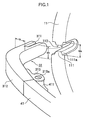
- Fig. 1 is an explanatory diagram of the main parts of rimless spectacles relating to an embodiment of the present invention
- Fig. 2 is a plan of rimless spectacles relating to an embodiment of the present invention
- Fig. 3 is a front elevation of rimless spectacles relating to an embodiment of the present invention
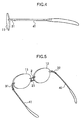
- Fig. 4 is a side elevation of rimless spectacles relating to an embodiment of the present invention
- Fig. 5 is a diagonal view of rimless spectacles relating to an embodiment of the present invention.
- symbols 11 and 12 indicate left and right spectacle lenses. These spectacle lenses 11 and 12 are joined by a bridge 2. To that bridge 2 is attached a nose piece 21. To the edges on the left and right extremities of the left and right lenses 11 and 12, respectively, are attached attachment members 31 and 32. To those attachment members 31 and 32 are respectively attached left and right temples 41 and 42.
- a cutout 110 is formed in the edge at the left extremity of the spectacle lens 11, such that the front end of the attachment member 31 can be pushed into place in the cutout 110.
- This cutout 110 has a substantially constant width from the edge of the spectacle lens 11 toward the center thereof, and has a ridge 111 that is substantially parallel to the front and back surfaces of the spectacle lens 11 formed in the inner circumferential wall part thereof.
- the attachment member 31 has a groove 311 formed therein, into which the ridge 111 of the cutout 110 fits, where the attachment member 31 abuts on the inner circumferential wall part of the cutout 110, when that attachment member 31 is inserted and pushed into place in the cutout 110 from the edge of the spectacle lens 11. That is, this attachment member 31 is designed so that, the attachment member 31 is attached to the cutout 110 by inserted the attachment member 31 into the cutout 110 from the edge of the spectacle lens 11, and pushing it into place so that the groove 311 in the attachment member 31 fits over the ridge 111 in the cutout 110. After the attachment member 31 is pushed into place in the cutout 110, it is secured with an adhesive or the like.
- the attachment member 31 has an end piece 312 formed therein that bends toward the end thereof opposite the site of attachment to the spectacle lens 11 until it is in a direction substantially orthogonal to the front and back surfaces of the spectacle lens 11 on the face side.
- a hinge member 313 that constitutes a hinge structure for attaching a temple 41 so that it can be freely folded over.
- This hinge member 313 is joined to a hinge member 411 secured to the temple 41 and fixed in place with a screw 313a.
- the temple 41 is attached to the attachment member 31 such that it can be freely folded over.
- the attachment member 32 that is attached to the right spectacle lens 12 is attached in the same way as described above.
- the attachment to the spectacle lenses to the left and right of the bridge 2 is the same, wherefore no further explanation therefor is given here.
- the width Wt of the attachment member 31 corresponding to the width Wk of the cutout 110 is formed so as to be substantially equal to the width Wk of the cutout 110 except where the groove 311 is formed.
- the side surface 111a of the ridge 111 in the cutout 110 in this embodiment, is made an inclined surface with an inclination of approximately 30° or so.
- the width Tt in the lens thickness direction in the cutout 110 of the attachment member 31 is made substantially the same as the thickness of the spectacle lens 11.
- Fig. 6 provides cross-sectional views of portions wherein an attachment member 31 is pushed into place and secured in a cutout 110 in a spectacle lens 11.
- Fig. 6(a) represents the case of this embodiment.
- the cutting plane in this cross-sectional view is perpendicular to a straight line extending from the edge of the spectacle lens 11 to the center thereof.
- the side surface 111a of the ridge 111 in the cutout 110 is given an inclination, but it may also be made a perpendicular surface as diagrammed in Fig. 6(b).
- the width Tt in the lens thickness direction of the attachment member 31 is made substantially the same as the thickness of the spectacle lens 11, but it may also be formed thinner than the thickness of the spectacle lens 11 as diagrammed in Fig. 6(c).
- the width Wk of the cutout 110 and the width Wt of the attachment member 31 are made substantially equal, attachment can be effected using common attachment members even if the lens thickness changes, there ceases to be a need to fabricate attachment members for each lens, parts can be used in common, and extremely high utility can be realized.
- the upper surface of the ridge 111 in the cutout 110 may be flat, or it may have one or more grooves 111b in it as diagrammed in Fig. 6(d). In the latter case, when securing is done using an adhesive, the grooves 111b act as adhesive reservoirs and a strong bond can be effected. In the embodiment described in the foregoing, furthermore, an example is given wherein one ridge 111 is provided, but a plurality thereof may be provided.
- the cross-sectional shapes of the ridge 111 in the cutout 110 and the groove 311 in the attachment member 31 may also be a simple V shape, a semi-cylindrical shape, or some other shape.
- Fig. 7 provides diagrams of still other examples of cutouts 110.
- the cutout 110 may be made in a shape such that, as diagrammed in Fig. 7(a), at least either the front or the back surface of the spectacle lens 11 (the side toward the eye being diagrammed in the figure) is closed. If this is done, when the lens periphery is thick (as in the case of a lens of strong minus power), the portion removed in machining when forming the cutout can be diminished, making it possible to realize good results in terms of machinability, exterior appearance, and/or strength.
- the ridge 111 may have one side surface 111a which is coincide with the front surface of the spectacle lens 11, as diagrammed in Fig. 7(b).
- Fig. 7(b) Alternatively, as diagrammed in Fig.
- a groove 112 may be provided in the cutout 11 instead of the ridge 111, and a ridge 312 in the attachment member 31 instead of the groove 311.
- the shape may be made so that at least either the front or the back surface of the spectacle lens 11 (the side toward the eye being diagrammed in the figure) is closed, as diagrammed in Fig. 7(d).
- the spectacle lenses 11 and 12 are configured of a material such as glass or plastic.
- examples of such materials include diethylene glycol allyl carbonate or polycarbonates, and acrylic or polyurethane resins.
- Polyurethane type lenses are particularly desirable for the spectacle lens holding structures in this embodiment as they exhibit superior shock resistance and tensile strength, etc.
- resins as polyamides, polyimides, acetates, polyetherimides, polyether ether ketones, and polyphenyl sulfones
- metal materials as titanium or titanium alloys, iron-based alloys, nickel silver, Monel metal, high nickel, stainless steel or other nickel alloys, and bronze, beryllium-copper, or other copper alloy, or other materials.
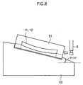
- Fig. 8 is an explanatory diagram for an example of a machining method for the cutout 110.
- the symbol 51 is a form that secures the spectacle lens 11 or 12, while 52 is an angled holding pedestal that holds that form at some angle.
- the lens 11 or 12 is inserted in the form 51 with the convex surface down, and the form 51 is secured on the. angle holding pedestal 52.
- a 12-degree angle holding pedestal is used to match the average curve of the convex lens surface. In this condition, by cutting the lens horizontally while turning a cutter 6, a cutout 110 like that diagrammed in Fig. 1 can be formed.
- Fig. 9 is an explanatory diagram for a method of machining a lens wherein a block for machining the lens is chucked as it is without using a form or angle holding pedestal.
- This is a method of machining the lenses 11 and 12 by using a block 7, as is, that securely holds the lens in place for that purpose. That is, the block is chucked as is in an NC machining apparatus or the like and a cutter is brought to bear from a direction of 12 degrees. If this is done, it is extremely easy to automate the cutout machining.
- Fig. 10 diagrams examples of cutters used when forming cutouts of various different shapes.
- Fig. 10(a) to 10(d) 12° when the lens periphery is thick (when the lens has a strong minus power), the back lens surface (on the eye side) will be greatly removed.
- Fig. 11(a) is a diagram which represents an example of cutout machining when the lens periphery is thick. As diagrammed in Fig.
- the back lens surface side (side toward the eye) is removed by a distance D from the edge toward the center. Thereupon, when seen from the outside, the cut appears as a projected image toward the direction of observation.
- the size d thereof becomes approximately 0.8 millimeters in the case of this embodiment.
- the cutter diagrammed in Fig. 10(e) is used.
- This cutter is a cutter that has been cut by the amount of the angle wherewith the lens is tilted (12 degrees in this embodiment).
- cutout machining can be performed which parallels the lens edge surface, and strength and outward appearance are no longer impaired more than necessary.
- the cutter diagrammed in Fig. 10(f) is used.
- the spectacle lens 11 is secured in a spectacle lens securing apparatus 500 wherewith it can be positioned and secured. Then, positioning is done by a positioning reference plate 700 wherewith accurate positioning can be performed by pushing the edge of the spectacle lens 11 against the reference surface. Next, machining is performed by a cutter 6 attached to an NC machining apparatus 600.
- the attachment member 31 is joined and secured by a ridge 111 provided in the cutout 110 and a groove 311 provided in the attachment member 31. Therefore, so long as there is sufficient thickness in the lens periphery for the ridge 111 to be formed by machining in the cutout 110, even a thin lens can be firmly secured.
- the cutout 110 can be made in a form wherein one surface side of the lens is closed, as diagrammed in Fig. 7(a) and 7(d). Accordingly, firm securing can be done, regardless of whether the lens is thin or thick, while good design factors can also be maintained, wherefore the product value of the spectacles can be significantly enhanced.
- the joined portion thereof cannot be seen looking at the eyeglass frame from the front.
- the color of the adhesive changes over time, or there is any slight admixture of air bubbles in the joined portion, that will not be conspicuous.
- the fitted securing portion is machined integrally into the front end of the attachment member, it is possible to position the securing portion so that there is no sense of incongruity with the end pieces or bridge, and a natural outer appearance can be provided because no sharp pin-shaped projection comes in front of the eyes as with the PinFeel type.
- the adhesive used here may be an epoxy, acrylic, cyanoacrylate, or anaerobic type adhesive or the like.
- Epoxy adhesives in particular, exhibit outstanding adhesive effect irrespective of the lens material.
- the adhesive used should be a highly transparent adhesive of low viscosity, exhibiting a viscosity when used at 25°C of 3000 poises or so. With a low-viscosity adhesive, there is little generation of air bubbles, and workability is outstanding.
- an acrylic type lens is used for the spectacle lenses, furthermore, because such acrylic lenses are generally not highly resistant to solvents, it is preferable that an epoxy type adhesive be used.
- the surface thereof may be roughened so that it is uneven, or portions of the groove may be made deeper to create reservoirs for the adhesive, and thus the adhesive strength can be dramatically increased.
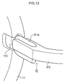
- Fig. 13 is an explanatory diagram for the main parts of rimless spectacles relating to another embodiment of the present invention.
- a groove is provided in the cutout 110 and a ridge is provided in the attachment member 31.
- the configuration is the same as in the embodiment described in the foregoing, wherefore no detailed description thereof is given here.
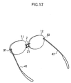
- Fig. 14 to 17 are diagrams representing still other embodiments.
- the attachment member used for the attachment member 31 is of a shape wherein the end piece 312 has been eliminated from the attachment member 31, a hinge structure is formed directly on this attachment member 31, and the temple is attached directly such that it can fold over. Based on these embodiments, as compared to conventional rimless spectacles having end pieces, it is possible to effect revolutionary new designs that are simple and abound in functional beauty.
- the attachment member 31 is formed in substantially the same size as the cutout 110, provision is made so that the entire attachment member 31 is accommodated inside the cutout 110, a hinge structure 314 is provided in the attachment member 31 that is pushed into place inside the cutout 110, a hinge coupling is effected with the hinge structure 414 provided at the front end of the temple 41, and the temple is attached directly so that it can be freely folded over.
- the attachment member 31 is formed so that the depth dimension thereof is slightly longer than the cutout 110, provision is made so that the back end of the attachment member 31 protrudes slightly from the edge of the spectacle lens, a hinge structure 314 is formed at that protruding place, a hinge coupling is effected with the hinge structure 414 provided in the front end of the temple 41, and the temple is attached with a screw 314a so that it can be folded over freely.
- the screw 314a configuring the hinge structure can be adjusted at any time.
- the attachment member 31 is formed in substantially the same size as the cutout 110, provision is made so that the entire attachment member 31 is accommodated inside the cutout 110, a hinge structure 314a is provided on the side of the cutout 110 toward the eye, a hinge coupling is effected with the hinge structure 414 provided in the front end of the temple 41, and the temple is attached so that it can be folded over freely. Based on this, it is easy to make it so that the end piece and hinge structure cannot be seen at all from the front. Also, even when the lens edge thickness is thick (in a case like that diagrammed in Fig. 6(c)), by lengthening the hinge structure 314a on the face side, the screw 314a of the hinge structure is brought out to the outside, and a structure can be effected that is adjustable at any time.
- the groove or ridge provided in the attachment member is mated with the ridge or groove provided in the cutout and secured, wherefore not only is strong securing made possible, but the following benefits are realized.
- the present invention provides rimless spectacles wherein cutouts are provided in the edges of spectacle lenses and attachment members are pushed into place in those cutouts and attached.
- the cutouts have widths that are either substantially constant or gradually narrow from the edge of the lens toward the center thereof, with ridges or grooves substantially parallel to the front and back surfaces of the spectacle lenses formed in the inner circumferential wall parts thereof.
- the attachment members have grooves or ridges formed therein that, when those attachment members are inserted into the cutouts from the edge sides of the spectacle lenses and pushed into place, mate with ridges or grooves in the cutouts where the attachment members abut on the inner circumferential wall parts of the cutouts.
- the rimless spectacles of the present invention are characterized in that the attachment members are attached by being inserted from the edge sides of the spectacle lenses into the cutouts and pushed into place therein. Rimless spectacles are therefore obtained wherewith simple, definite, and firm attachment is possible, breadth of effective field of view, durability, aesthetic beauty, and lighter weight, etc., are readily secured, and fabrication is easy.
Landscapes
- Engineering & Computer Science (AREA)
- Physics & Mathematics (AREA)
- Mechanical Engineering (AREA)
- Health & Medical Sciences (AREA)
- General Physics & Mathematics (AREA)
- Ophthalmology & Optometry (AREA)
- Optics & Photonics (AREA)
- Chemical & Material Sciences (AREA)
- Ceramic Engineering (AREA)
- Inorganic Chemistry (AREA)
- Eyeglasses (AREA)
- Laser Surgery Devices (AREA)
Abstract
Description
Claims (5)
- Rimless spectacles which are designed so that cutouts are provided in edges of spectacle lenses and attachment members are fit into those cutouts and attached thereto without using rims, wherein:said cutouts have widths that are either substantially constant or gradually narrow from the edges of said spectacle lenses toward the centers thereof, and have ridges, substantially parallel to the front and back surfaces of said spectacle lenses, formed in the inner circumferential walls thereof;said attachment members have grooves formed therein which, when said attachment members are inserted and pushed into place in said cutouts from the edge sides of said spectacle lenses, fit over said ridges in said cutouts where said attachment pieces abut on the inner circumferential walls of said cutouts; andsaid attachment members are attached to said cutouts by inserting said attachment members into said cutouts from the edge side of said spectacle lenses and pushing them into place so that said grooves in said attachment members fit over said ridges in said cutouts.
- Rimless spectacles which are designed so that cutouts are provided in edges of spectacle lenses and attachment members are fit into those cutouts and attached thereto without using rims, wherein:said cutouts have widths that are either substantially constant or gradually narrow from the edges of said spectacle lenses toward the centers thereof, and have grooves, substantially parallel to the front and back surfaces of said spectacle lenses, formed in the inner circumferential walls thereof;said attachment members have ridges formed therein which, when said attachment members are inserted and pushed into place in said cutouts from the edge sides of said spectacle lenses, fit into said grooves in said cutouts where said attachment pieces abut on the inner circumferential walls of said cutouts; andsaid attachment members are attached to said cutouts by inserting said attachment members into said cutouts from the edge side of said spectacle lenses and pushing them into place so that said ridges in said attachment members fit into said grooves in said cutouts.
- The rimless spectacles according to claim 1 or 2, wherein widths of said attachment members are either substantially equal to or smaller than widths of said cutouts.
- The rimless spectacles according to any one of claims 1 to 3, wherein said cutouts constitute shapes such that at least one or other of front and back surfaces of said spectacle lens is closed.
- Rimless spectacles comprising attachment structures for directly attaching attachment members to edges of spectacle lenses without using rims, in which hinge structures are provided in said attachment members so that temples can be attached such that the temples can be folded over;
wherein said attachment members do not have end pieces extending in directions substantially orthogonal to the front and back surfaces of said spectacle lenses, but hinge structures are formed directly at the sites where said attachment members are attached to said spectacle lenses and said temples are attached such that the temples can be folded over.
Applications Claiming Priority (5)
| Application Number | Priority Date | Filing Date | Title |
|---|---|---|---|
| JP2000124025 | 2000-04-25 | ||
| JP2000124025 | 2000-04-25 | ||
| JP2001115338 | 2001-04-13 | ||
| JP2001115338A JP3737957B2 (en) | 2000-04-25 | 2001-04-13 | Rimless glasses |
| PCT/JP2001/003402 WO2001081983A1 (en) | 2000-04-25 | 2001-04-20 | Rimless spectacles |
Publications (3)
| Publication Number | Publication Date |
|---|---|
| EP1278095A1 true EP1278095A1 (en) | 2003-01-22 |
| EP1278095A4 EP1278095A4 (en) | 2005-01-26 |
| EP1278095B1 EP1278095B1 (en) | 2009-01-07 |
Family
ID=26590732
Family Applications (1)
| Application Number | Title | Priority Date | Filing Date |
|---|---|---|---|
| EP01921953A Expired - Lifetime EP1278095B1 (en) | 2000-04-25 | 2001-04-20 | Rimless spectacles |
Country Status (11)
| Country | Link |
|---|---|
| US (1) | US6540350B2 (en) |
| EP (1) | EP1278095B1 (en) |
| JP (1) | JP3737957B2 (en) |
| KR (1) | KR100578947B1 (en) |
| CN (1) | CN1272653C (en) |
| AT (1) | ATE420384T1 (en) |
| AU (1) | AU781738B2 (en) |
| DE (1) | DE60137320D1 (en) |
| MY (1) | MY119103A (en) |
| TW (2) | TWI245942B (en) |
| WO (1) | WO2001081983A1 (en) |
Cited By (1)
| Publication number | Priority date | Publication date | Assignee | Title |
|---|---|---|---|---|
| FR2890458A1 (en) * | 2005-09-07 | 2007-03-09 | Guy Millot | INTERFACE FOR MOUNTING A GLASS OF A GLASS ON A FRAME FIXED IN A CUTTING OF THE GLASS AND EYEGLASS HAVING THE SAME INTERFACE. |
Families Citing this family (27)
| Publication number | Priority date | Publication date | Assignee | Title |
|---|---|---|---|---|
| US6786594B1 (en) * | 2003-03-14 | 2004-09-07 | Fore-Z (H.K.) Limited | Hinge for eyewear |
| US6641265B1 (en) * | 2003-03-25 | 2003-11-04 | Su-Fen Hou | Eyeglasses with coupling members for interconnecting temples and lenses thereof |
| US7011405B2 (en) * | 2003-11-04 | 2006-03-14 | Hongbiao Chen | Flexible glasses frame |
| DE102004018080A1 (en) * | 2004-04-08 | 2005-10-27 | Rodenstock Gmbh | Spectacle frame with screwless, flush glass mounting |
| EP1794641B1 (en) * | 2004-09-30 | 2010-07-07 | Safilo Societa' Azionaria Fabbrica Italiana Lavorazione Occhiali S.p.a. | Improved spectacles, particularly of the type without lens-carrying rims |
| EP1847869B1 (en) | 2004-10-25 | 2016-06-29 | Hoya Corporation | Device and method for measuring and machining spectacle lens, spectacle lens manufacturing method, and spectacles manufacturing method |
| KR200385176Y1 (en) * | 2005-01-14 | 2005-05-25 | 임언수 | Glasses |
| WO2007104414A1 (en) * | 2006-03-10 | 2007-09-20 | Allison S.P.A. | Connector for attaching a bow to a lens |
| ATE552526T1 (en) | 2006-12-08 | 2012-04-15 | Hoya Corp | PLASTIC LENS FOR EYEGLASSES AND PRODUCTION PROCESS THEREOF |
| CN101373276B (en) * | 2007-08-22 | 2011-10-19 | 萧榆 | rimless glasses |
| AU2009239022B2 (en) * | 2008-04-22 | 2013-07-11 | Hoya Corporation | Holding structure for eyeglass lens, eyeglasses, and method of producing eyeglasses |
| US8465149B2 (en) * | 2008-09-23 | 2013-06-18 | Yu SIU | Spectacles |
| US7967431B2 (en) * | 2008-09-23 | 2011-06-28 | Siu Yu | Spectacles |
| US7789506B1 (en) * | 2009-01-08 | 2010-09-07 | Jong Kim | Frame locking device for eyeglasses |
| JP2011002808A (en) * | 2009-05-21 | 2011-01-06 | Kawamoto Kogaku Kogyo Kk | Lens fixing method for rimless eyeglasses, and rimless eyeglasses using the same |
| USD682924S1 (en) * | 2011-09-30 | 2013-05-21 | Chuen Fung Spectacles Services Manufactory Limited | Spring hinge |
| JP2014052477A (en) * | 2012-09-06 | 2014-03-20 | Onaga Megane:Kk | Temple joint structure of spectacle frame |
| KR200467559Y1 (en) | 2012-10-04 | 2013-06-19 | 김시영 | Glasses |
| DE102013101458B4 (en) * | 2013-02-14 | 2016-11-10 | Inomitec Gmbh & Co. Kg | Device and method for the direct attachment of at least one bracket, a jaw and / or bridge of a spectacle frame to at least one spectacle lens of rimless spectacles |
| US20140333887A1 (en) * | 2013-05-07 | 2014-11-13 | Yu SIU | Spectacles |
| CN203414687U (en) * | 2013-08-07 | 2014-01-29 | 钟志安 | detachable combination glasses |
| DE102014105062A1 (en) * | 2014-04-09 | 2015-10-15 | Inomitec Gmbh & Co. Kg | Device and method for the direct attachment of at least one bracket, a jaw and / or bridge of a spectacle frame to at least one spectacle lens of rimless spectacles |
| US20170160561A1 (en) * | 2014-04-30 | 2017-06-08 | Oceanus Investment Inc. | Rimless eyeglasses |
| WO2016095910A1 (en) * | 2014-12-19 | 2016-06-23 | Inomitec Gmbh & Co. Kg | Device and method for the direct attachment of at least a temple, an endpiece and/or a bridge of a glasses frame to at least one lens of rimless glasses |
| US20180275422A1 (en) * | 2015-08-28 | 2018-09-27 | Hoya Lens Thailand Ltd. | Spectacles |
| AT520704A1 (en) * | 2017-12-01 | 2019-06-15 | Silhouette Int Schmied Ag | Frameless glasses |
| KR102667165B1 (en) | 2022-05-17 | 2024-05-20 | 주식회사 한국 오.지.케이 | Eyewear |
Family Cites Families (12)
| Publication number | Priority date | Publication date | Assignee | Title |
|---|---|---|---|---|
| JPH0813207B2 (en) | 1989-07-10 | 1996-02-14 | 株式会社クボタ | Seedling transplanter |
| JP3514485B2 (en) | 1993-06-22 | 2004-03-31 | 日本エア・リキード株式会社 | High-purity nitrogen gas production equipment |
| JP2602605Y2 (en) | 1993-11-22 | 2000-01-24 | 株式会社村井 | Eye mirror |
| JPH07333563A (en) | 1994-06-08 | 1995-12-22 | Mitsuo Kobayashi | Connecting structure of spectacle temple of rimless spectacles |
| FR2726096B1 (en) * | 1994-10-21 | 1997-01-03 | Robert Bac | EYEWEAR FRAME AND ASSEMBLY METHOD FOR ORGANIC LENSES |
| US5646706A (en) * | 1994-12-21 | 1997-07-08 | Hoya Corporation | Spectacle lens holding structure |
| JPH0933861A (en) | 1995-07-20 | 1997-02-07 | Aoyama Megane Kk | Lens fixing mechanism for rimless spectacles |
| JPH09325301A (en) | 1996-05-31 | 1997-12-16 | Hideaki Tachibana | Lens fixing mechanism of rimless spectacles |
| US5847800A (en) * | 1996-12-13 | 1998-12-08 | Tachibana; Hideaki | Lens holding mechanism of spectacles |
| JP2997438B2 (en) | 1996-12-13 | 2000-01-11 | 英明 橘 | Lens fastening mechanism for rimless spectacles |
| JPH1110427A (en) * | 1997-06-16 | 1999-01-19 | Miki:Kk | Groove cutting machine for spectacle lens |
| JP3043006B2 (en) | 1998-04-09 | 2000-05-22 | 花王株式会社 | Laundry aid |
-
2001
- 2001-04-13 JP JP2001115338A patent/JP3737957B2/en not_active Expired - Lifetime
- 2001-04-20 EP EP01921953A patent/EP1278095B1/en not_active Expired - Lifetime
- 2001-04-20 KR KR1020027014179A patent/KR100578947B1/en not_active Expired - Lifetime
- 2001-04-20 AU AU48810/01A patent/AU781738B2/en not_active Expired
- 2001-04-20 AT AT01921953T patent/ATE420384T1/en not_active IP Right Cessation
- 2001-04-20 WO PCT/JP2001/003402 patent/WO2001081983A1/en not_active Ceased
- 2001-04-20 DE DE60137320T patent/DE60137320D1/en not_active Expired - Lifetime
- 2001-04-20 US US09/856,123 patent/US6540350B2/en not_active Expired - Lifetime
- 2001-04-20 CN CNB018037178A patent/CN1272653C/en not_active Expired - Lifetime
- 2001-04-25 TW TW090109864A patent/TWI245942B/en not_active IP Right Cessation
- 2001-04-25 MY MYPI20011935A patent/MY119103A/en unknown
- 2001-04-25 TW TW094101380A patent/TWI247925B/en not_active IP Right Cessation
Cited By (2)
| Publication number | Priority date | Publication date | Assignee | Title |
|---|---|---|---|---|
| FR2890458A1 (en) * | 2005-09-07 | 2007-03-09 | Guy Millot | INTERFACE FOR MOUNTING A GLASS OF A GLASS ON A FRAME FIXED IN A CUTTING OF THE GLASS AND EYEGLASS HAVING THE SAME INTERFACE. |
| WO2007028893A3 (en) * | 2005-09-07 | 2007-05-03 | Guy Millot | Interface for mounting a spectacle lens on a frame bonded in a lens cutout and spectacles comprising same |
Also Published As
| Publication number | Publication date |
|---|---|
| TW200517698A (en) | 2005-06-01 |
| KR100578947B1 (en) | 2006-05-12 |
| EP1278095A4 (en) | 2005-01-26 |
| JP3737957B2 (en) | 2006-01-25 |
| CN1272653C (en) | 2006-08-30 |
| TWI247925B (en) | 2006-01-21 |
| JP2002014303A (en) | 2002-01-18 |
| AU4881001A (en) | 2001-11-07 |
| DE60137320D1 (en) | 2009-02-26 |
| MY119103A (en) | 2005-03-31 |
| AU781738B2 (en) | 2005-06-09 |
| HK1050568A1 (en) | 2003-06-27 |
| WO2001081983A1 (en) | 2001-11-01 |
| CN1395696A (en) | 2003-02-05 |
| TWI245942B (en) | 2005-12-21 |
| EP1278095B1 (en) | 2009-01-07 |
| US20020135732A1 (en) | 2002-09-26 |
| US6540350B2 (en) | 2003-04-01 |
| ATE420384T1 (en) | 2009-01-15 |
| KR20020093064A (en) | 2002-12-12 |
Similar Documents
| Publication | Publication Date | Title |
|---|---|---|
| EP1278095B1 (en) | Rimless spectacles | |
| US4255024A (en) | Spectacles frame of wood | |
| US7344241B2 (en) | Glasses having frame for combined use with a cap | |
| US20060238698A1 (en) | Eyewear having lenses with rims | |
| US7370961B2 (en) | Interchangeable eyewear assembly | |
| WO1999050703A1 (en) | Sunglasses with interchangeable lenses | |
| JPH11237589A (en) | Spectacles | |
| WO1997016761A1 (en) | Magnetic eyewear system | |
| US5406337A (en) | Semi-rimless eyeglass frame assembly | |
| JP2854531B2 (en) | Eyeglass lens holding structure | |
| JP4169160B2 (en) | Rimless glasses and manufacturing method thereof | |
| EP1176453B1 (en) | Glasses | |
| JP2009047862A (en) | A pair of right and left eyeglass lenses of right and left integral type, and right and left integral type eyeglasses | |
| JPH10282455A (en) | Rimless glasses connecting structure and glasses consisting of the connecting structure | |
| CN223565994U (en) | Novel glasses structure with metal sleeve adhesive | |
| CN2480872Y (en) | Glasses capable of easy replacing lens | |
| CN216351603U (en) | Glasses | |
| CN210803883U (en) | Frame and sheet integrated glasses | |
| JPH1062721A (en) | Rimless glasses | |
| JP3447462B2 (en) | Eyeglass lens holding structure | |
| CN211263994U (en) | Combined glasses | |
| JP2001194630A (en) | Frameless glasses | |
| KR200385176Y1 (en) | Glasses | |
| KR200381236Y1 (en) | Half-rim Glasses | |
| CA2480532A1 (en) | Eyewear with interchangeable lenses |
Legal Events
| Date | Code | Title | Description |
|---|---|---|---|
| PUAI | Public reference made under article 153(3) epc to a published international application that has entered the european phase |
Free format text: ORIGINAL CODE: 0009012 |
|
| 17P | Request for examination filed |
Effective date: 20020805 |
|
| AK | Designated contracting states |
Kind code of ref document: A1 Designated state(s): AT BE CH CY DE DK ES FI FR GB GR IE IT LI LU MC NL PT SE TR |
|
| AX | Request for extension of the european patent |
Free format text: AL;LT;LV;MK;RO;SI |
|
| A4 | Supplementary search report drawn up and despatched |
Effective date: 20041209 |
|
| GRAJ | Information related to disapproval of communication of intention to grant by the applicant or resumption of examination proceedings by the epo deleted |
Free format text: ORIGINAL CODE: EPIDOSDIGR1 |
|
| GRAP | Despatch of communication of intention to grant a patent |
Free format text: ORIGINAL CODE: EPIDOSNIGR1 |
|
| GRAP | Despatch of communication of intention to grant a patent |
Free format text: ORIGINAL CODE: EPIDOSNIGR1 |
|
| GRAS | Grant fee paid |
Free format text: ORIGINAL CODE: EPIDOSNIGR3 |
|
| GRAA | (expected) grant |
Free format text: ORIGINAL CODE: 0009210 |
|
| AK | Designated contracting states |
Kind code of ref document: B1 Designated state(s): AT BE CH CY DE DK ES FI FR GB GR IE IT LI LU MC NL PT SE TR |
|
| REG | Reference to a national code |
Ref country code: GB Ref legal event code: FG4D |
|
| REG | Reference to a national code |
Ref country code: CH Ref legal event code: EP |
|
| REG | Reference to a national code |
Ref country code: IE Ref legal event code: FG4D |
|
| REF | Corresponds to: |
Ref document number: 60137320 Country of ref document: DE Date of ref document: 20090226 Kind code of ref document: P |
|
| PG25 | Lapsed in a contracting state [announced via postgrant information from national office to epo] |
Ref country code: ES Free format text: LAPSE BECAUSE OF FAILURE TO SUBMIT A TRANSLATION OF THE DESCRIPTION OR TO PAY THE FEE WITHIN THE PRESCRIBED TIME-LIMIT Effective date: 20090418 Ref country code: FI Free format text: LAPSE BECAUSE OF FAILURE TO SUBMIT A TRANSLATION OF THE DESCRIPTION OR TO PAY THE FEE WITHIN THE PRESCRIBED TIME-LIMIT Effective date: 20090107 |
|
| PG25 | Lapsed in a contracting state [announced via postgrant information from national office to epo] |
Ref country code: PT Free format text: LAPSE BECAUSE OF FAILURE TO SUBMIT A TRANSLATION OF THE DESCRIPTION OR TO PAY THE FEE WITHIN THE PRESCRIBED TIME-LIMIT Effective date: 20090608 Ref country code: SE Free format text: LAPSE BECAUSE OF FAILURE TO SUBMIT A TRANSLATION OF THE DESCRIPTION OR TO PAY THE FEE WITHIN THE PRESCRIBED TIME-LIMIT Effective date: 20090407 Ref country code: AT Free format text: LAPSE BECAUSE OF FAILURE TO SUBMIT A TRANSLATION OF THE DESCRIPTION OR TO PAY THE FEE WITHIN THE PRESCRIBED TIME-LIMIT Effective date: 20090107 |
|
| PG25 | Lapsed in a contracting state [announced via postgrant information from national office to epo] |
Ref country code: BE Free format text: LAPSE BECAUSE OF FAILURE TO SUBMIT A TRANSLATION OF THE DESCRIPTION OR TO PAY THE FEE WITHIN THE PRESCRIBED TIME-LIMIT Effective date: 20090107 |
|
| PG25 | Lapsed in a contracting state [announced via postgrant information from national office to epo] |
Ref country code: DK Free format text: LAPSE BECAUSE OF FAILURE TO SUBMIT A TRANSLATION OF THE DESCRIPTION OR TO PAY THE FEE WITHIN THE PRESCRIBED TIME-LIMIT Effective date: 20090107 |
|
| PLBE | No opposition filed within time limit |
Free format text: ORIGINAL CODE: 0009261 |
|
| STAA | Information on the status of an ep patent application or granted ep patent |
Free format text: STATUS: NO OPPOSITION FILED WITHIN TIME LIMIT |
|
| REG | Reference to a national code |
Ref country code: CH Ref legal event code: PL |
|
| 26N | No opposition filed |
Effective date: 20091008 |
|
| PG25 | Lapsed in a contracting state [announced via postgrant information from national office to epo] |
Ref country code: LI Free format text: LAPSE BECAUSE OF NON-PAYMENT OF DUE FEES Effective date: 20090430 Ref country code: CH Free format text: LAPSE BECAUSE OF NON-PAYMENT OF DUE FEES Effective date: 20090430 |
|
| REG | Reference to a national code |
Ref country code: IE Ref legal event code: MM4A |
|
| PG25 | Lapsed in a contracting state [announced via postgrant information from national office to epo] |
Ref country code: IE Free format text: LAPSE BECAUSE OF NON-PAYMENT OF DUE FEES Effective date: 20090420 Ref country code: MC Free format text: LAPSE BECAUSE OF NON-PAYMENT OF DUE FEES Effective date: 20090430 |
|
| PG25 | Lapsed in a contracting state [announced via postgrant information from national office to epo] |
Ref country code: GR Free format text: LAPSE BECAUSE OF FAILURE TO SUBMIT A TRANSLATION OF THE DESCRIPTION OR TO PAY THE FEE WITHIN THE PRESCRIBED TIME-LIMIT Effective date: 20090408 |
|
| PG25 | Lapsed in a contracting state [announced via postgrant information from national office to epo] |
Ref country code: IT Free format text: LAPSE BECAUSE OF FAILURE TO SUBMIT A TRANSLATION OF THE DESCRIPTION OR TO PAY THE FEE WITHIN THE PRESCRIBED TIME-LIMIT Effective date: 20090107 |
|
| PG25 | Lapsed in a contracting state [announced via postgrant information from national office to epo] |
Ref country code: LU Free format text: LAPSE BECAUSE OF NON-PAYMENT OF DUE FEES Effective date: 20090420 |
|
| PG25 | Lapsed in a contracting state [announced via postgrant information from national office to epo] |
Ref country code: TR Free format text: LAPSE BECAUSE OF FAILURE TO SUBMIT A TRANSLATION OF THE DESCRIPTION OR TO PAY THE FEE WITHIN THE PRESCRIBED TIME-LIMIT Effective date: 20090107 |
|
| PG25 | Lapsed in a contracting state [announced via postgrant information from national office to epo] |
Ref country code: CY Free format text: LAPSE BECAUSE OF FAILURE TO SUBMIT A TRANSLATION OF THE DESCRIPTION OR TO PAY THE FEE WITHIN THE PRESCRIBED TIME-LIMIT Effective date: 20090107 |
|
| REG | Reference to a national code |
Ref country code: FR Ref legal event code: PLFP Year of fee payment: 16 |
|
| REG | Reference to a national code |
Ref country code: FR Ref legal event code: PLFP Year of fee payment: 17 |
|
| REG | Reference to a national code |
Ref country code: FR Ref legal event code: PLFP Year of fee payment: 18 |
|
| PGFP | Annual fee paid to national office [announced via postgrant information from national office to epo] |
Ref country code: NL Payment date: 20200312 Year of fee payment: 20 |
|
| PGFP | Annual fee paid to national office [announced via postgrant information from national office to epo] |
Ref country code: FR Payment date: 20200312 Year of fee payment: 20 |
|
| PGFP | Annual fee paid to national office [announced via postgrant information from national office to epo] |
Ref country code: DE Payment date: 20200408 Year of fee payment: 20 |
|
| PGFP | Annual fee paid to national office [announced via postgrant information from national office to epo] |
Ref country code: GB Payment date: 20200408 Year of fee payment: 20 |
|
| REG | Reference to a national code |
Ref country code: DE Ref legal event code: R071 Ref document number: 60137320 Country of ref document: DE |
|
| REG | Reference to a national code |
Ref country code: NL Ref legal event code: MK Effective date: 20210419 |
|
| REG | Reference to a national code |
Ref country code: GB Ref legal event code: PE20 Expiry date: 20210419 |
|
| PG25 | Lapsed in a contracting state [announced via postgrant information from national office to epo] |
Ref country code: GB Free format text: LAPSE BECAUSE OF EXPIRATION OF PROTECTION Effective date: 20210419 |