EP1278024A1 - Method and device for stabilizing slit fluid jet - Google Patents
Method and device for stabilizing slit fluid jet Download PDFInfo
- Publication number
- EP1278024A1 EP1278024A1 EP00922894A EP00922894A EP1278024A1 EP 1278024 A1 EP1278024 A1 EP 1278024A1 EP 00922894 A EP00922894 A EP 00922894A EP 00922894 A EP00922894 A EP 00922894A EP 1278024 A1 EP1278024 A1 EP 1278024A1
- Authority
- EP
- European Patent Office
- Prior art keywords
- slit
- fluid jet
- fluid
- flow
- stabilizing
- Prior art date
- Legal status (The legal status is an assumption and is not a legal conclusion. Google has not performed a legal analysis and makes no representation as to the accuracy of the status listed.)
- Withdrawn
Links
- 239000012530 fluid Substances 0.000 title claims abstract description 118
- 238000000034 method Methods 0.000 title claims abstract description 9
- 230000000087 stabilizing effect Effects 0.000 title claims description 25
- 239000000126 substance Substances 0.000 description 11
- 230000000737 periodic effect Effects 0.000 description 9
- XLYOFNOQVPJJNP-UHFFFAOYSA-N water Substances O XLYOFNOQVPJJNP-UHFFFAOYSA-N 0.000 description 7
- 239000007788 liquid Substances 0.000 description 5
- 239000007787 solid Substances 0.000 description 5
- 241000251468 Actinopterygii Species 0.000 description 4
- 238000004299 exfoliation Methods 0.000 description 3
- 230000003993 interaction Effects 0.000 description 3
- XKRFYHLGVUSROY-UHFFFAOYSA-N Argon Chemical compound [Ar] XKRFYHLGVUSROY-UHFFFAOYSA-N 0.000 description 2
- 238000010586 diagram Methods 0.000 description 2
- 230000000694 effects Effects 0.000 description 2
- 238000002474 experimental method Methods 0.000 description 2
- 238000003754 machining Methods 0.000 description 2
- 235000019687 Lamb Nutrition 0.000 description 1
- 238000004378 air conditioning Methods 0.000 description 1
- 229910052786 argon Inorganic materials 0.000 description 1
- 238000007796 conventional method Methods 0.000 description 1
- 235000013611 frozen food Nutrition 0.000 description 1
- 238000004321 preservation Methods 0.000 description 1
- 238000010008 shearing Methods 0.000 description 1
- 230000009182 swimming Effects 0.000 description 1
- 238000011144 upstream manufacturing Methods 0.000 description 1
- 238000013316 zoning Methods 0.000 description 1
Images

Classifications
-
- F—MECHANICAL ENGINEERING; LIGHTING; HEATING; WEAPONS; BLASTING
- F24—HEATING; RANGES; VENTILATING
- F24F—AIR-CONDITIONING; AIR-HUMIDIFICATION; VENTILATION; USE OF AIR CURRENTS FOR SCREENING
- F24F13/00—Details common to, or for air-conditioning, air-humidification, ventilation or use of air currents for screening
- F24F13/02—Ducting arrangements
- F24F13/06—Outlets for directing or distributing air into rooms or spaces, e.g. ceiling air diffuser
-
- F—MECHANICAL ENGINEERING; LIGHTING; HEATING; WEAPONS; BLASTING
- F24—HEATING; RANGES; VENTILATING
- F24F—AIR-CONDITIONING; AIR-HUMIDIFICATION; VENTILATION; USE OF AIR CURRENTS FOR SCREENING
- F24F13/00—Details common to, or for air-conditioning, air-humidification, ventilation or use of air currents for screening
- F24F13/02—Ducting arrangements
- F24F13/06—Outlets for directing or distributing air into rooms or spaces, e.g. ceiling air diffuser
- F24F13/072—Outlets for directing or distributing air into rooms or spaces, e.g. ceiling air diffuser of elongated shape, e.g. between ceiling panels
-
- F—MECHANICAL ENGINEERING; LIGHTING; HEATING; WEAPONS; BLASTING
- F24—HEATING; RANGES; VENTILATING
- F24F—AIR-CONDITIONING; AIR-HUMIDIFICATION; VENTILATION; USE OF AIR CURRENTS FOR SCREENING
- F24F9/00—Use of air currents for screening, e.g. air curtains
-
- F—MECHANICAL ENGINEERING; LIGHTING; HEATING; WEAPONS; BLASTING
- F24—HEATING; RANGES; VENTILATING
- F24F—AIR-CONDITIONING; AIR-HUMIDIFICATION; VENTILATION; USE OF AIR CURRENTS FOR SCREENING
- F24F2221/00—Details or features not otherwise provided for
- F24F2221/28—Details or features not otherwise provided for using the Coanda effect
Definitions
- the invention of this application relates to a method of stabilizing a slit fluid jet and a device therefor. More particularly, the invention of this application concerns a method of stabilizing a slit fluid jet and a device therefor which are useful, especially for preventing fluid and solid from entering into a space of control from outside it, or for preventing fluid and solid from going out from the space of control into outside it.
- a slit fluid jet has hitherto been used as means for preventing fluid and solid from entering into the space of control from outside it, or for preventing fluid and solid from going out from the space of control into outside it.
- an air curtain that is a kind of slit fluid jet is ejected at each of the inlet and outlet thereof to thereby make effective the zoning between the space of control and the external air, thereby the air-conditioning efficiency is successfully enhanced.
- air curtains are ejected from the surroundings of a processing part thereof, to thereby form a space of cool air for the low-temperature preservation of foodstuff.
- liquid curtains or shower curtains are ejected from the surroundings of a machining part thereof, to thereby prevent cut shavings from being scattered, or splashing out, from the space of machining.
- this slit fluid jet such as the air curtain, liquid curtain, or shower curtain is formed by ejecting fluid from an apparatus using a pair of smooth flat surfaces or curved surfaces or an apparatus wherein the nozzles are arrayed.
- This likeliness to break of the fluid film of the slit fluid jet is attributable to the turbulence component (variable speed component) the fluid has.
- This turbulence component causes the exfoliation of the shearing layer on the inner wall of the slit, the creation of the exfoliation vortexes, the entrapment of air at the outlet of the slit, etc. It thereby makes the thickness of the fluid film of the slit fluid jet uneven, with the result that the fluid film becomes broken due even to a small intensity of disturbance.
- the above-described likeliness to break of the fluid film becomes serious as the distance as measured from the slit opening increases. Namely, as the distance from the slit opening increases, the thickness of the slit fluid jet becomes very small, so that it is easily broken due even to a very small magnitude of disturbance.
- an object of the present invention is to provide a method of stabilizing a slit fluid jet and a device therefor which enable a stable fluid film to be formed from the ejection opening of the slit over a long distance with that slit fluid jet being not broken.
- the invention of this application as means for solving the above-described problems, first, provides a method of stabilizing a slit fluid jet, comprising superimposing a fluid jet accompanied with a flip-flop phenomenon upon one, or both, of the surfaces of a slit fluid jet and thereby forming a stable said slit fluid jet.
- the invention of this application provides a stabilizing device for stabilizing a slit fluid jet, the stabilizing device being adapted to stabilize the slit fluid jet, comprising being equipped with two flat plates that oppose each other with a prescribed gap in between, one of the flat plates of the slit having an opposing surface that is smooth, the other having a network structure that has a plurality of crossed grooves that are crossed like a letter x.
- a stabilizing device for stabilizing the slit fluid jet wherein at an outlet of the fluid there are disposed flow passages of the network structure so that the fluids may be merged in.
- a stabilizing device for stabilizing the slit fluid jet, wherein the length between a detached vortex, occurring at the back of the crossed groove portion, and a point to that the detached vortex has been shifted is equal to or greater than the length of one side of a diamond-shaped protruding portion that is formed by the x-shaped grooves.
- the instability of the fluid film is attributable to the turbulence of the flow, i.e. the variable speed component.
- a fluid necessarily contains this variable speed component. Therefore, extreme difficulties are encountered in eliminating that turbulence.
- the invention of this application has performed hydrodynamic control with respect to the conventional simple slit fluid jet. More specifically, the invention of this application, in order to make uniform the non-uniformity of the fluid film thickness that results from the turbulence of the fluid, has formed a fluid film that has a two-layer structure of a slit fluid jet flow and a flip-flop flow. The invention of this application has resultantly added a mechanism for absorbing, with the lapse of time, the variable speed component that is contained in the slit fluid jet flow. In this respect, the invention of this application has a great characterizing feature.
- the inventors of this application have initially thought that, if a phenomenon peculiar to a fluid that occurs utilizing the variable speed in it as the energy of it is superimposed upon the slit fluid jet flow, a stable fluid film will be formed. Based on this idea, the inventors of this application has conceived the fact that a detached vortex, which appears in the flow at the back of a substance and which is typically represented by a Karman vortex, periodically occurs due to the existence of the variable speed component.
- the method of stabilizing the slit fluid jet flow according to the present invention, more specifically, if causing a fluid to be ejected from the slit opening to thereby form a slit fluid jet, superimposing a crossed flow, which is followed by the flip-flop phenomenon, upon this slit flow jet, and thereby causing the variable speed component energy of the slit fluid jet to be absorbed into the vibration component of the flip-flop crossed flow, a stable fluid film is formed.
- the flip-flop crossed flow is formed by means of a network terminal formed by a plurality of crossed grooves and causes the jet flow to periodically vibrate in the radial direction of it.
- This periodic vibration is caused by the flow of the fluid and this periodic vibration is amplified by the interaction between the ejected pieces of flow.
- This groove flow structure that is constructed of a plurality of groove flows acts to convert the turbulent component of the fluid into the periodic vibration component that is active in the radial direction of it.
- the network structure that is comprised of the flow passages formed by the grooves controls the turbulent component of the fluid, and causes the flip-flop phenomenon to occur at each of the points of merging of the groove flows and causes each of the groove flows to periodically vibrate in the radial direction of the groove.
- the slit fluid jet upon which this flip-flop crossed flow is superimposed becomes stabilized. This is because, if the jet flow followed by the flip-flop phenomenon exists on any one surface of the liquid film of the slit fluid jet, the component of fluctuation of the slit fluid jet is converted into the flip-flop phenomenon energy that is active upon that jet.
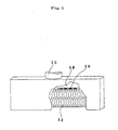
- a device for stabilizing the slit fluid jet according to the present invention includes, as an aspect, the one that has been illustrated in Fig. 1.
- This stabilizing device for the slit fluid jet is constructed of two flat plates (10) that oppose each other with a prescribed spacing in between.
- the inside of one of those flat plates is smooth while the other thereof has a network structure that has a plurality of crossed grooves (11) the configuration of that is shaped like a letter x.
- the flow passages of the network structure are located so that the pieces of fluid may merge in the flow-out opening of the fluid, and it is preferable that the distance from a detached vortex appearing at the back of each of the crossed portions to the point to which that detached vortex has been shifted be equal to or greater than one side of the diamond-shaped protruding portion formed by the x-shaped grooves.
- the flat plates (10) be flat surface members, they may be curved surface members. In that case, that the clearance that is the gap between the opposing members be equal, preferably, is made the requirement.
- a buffer region (12) for the fluid may be formed at one side of the clearance.
- the fluid that has been supplied from a fluid supply pipe (13) is allowed to flow between the paired opposing members, and this fluid is ejected as a slit fluid jet.
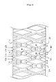
- Fig. 2 is a view illustrating, as a plan view, the member inside the slit that has a network structure.
- This member has provided therein as the passages of fluid a plurality of grooves 1a, b, c, ..., n and a plurality of grooves 2a, b, c, ..., n in the way both form net meshes.
- the respective ones of the grooves 1a, b, c, ..., n are provided at equal intervals and in parallel with one another, and the respective ones of the grooves 2a, b, c, ..., n are also provided in the same way.
- a plurality of grooves that are included in the angular region (A) defined between the flow and the main axis and a plurality of grooves that are included in the angular region (-A) that has been similarly defined are provided each in paired relationship with each other so that the pieces of fluid may merge together to go out from the ejection opening. Namely, they are provided so that the fluid that has been supplied from an inlet portion (IL) of the fluid may merge together at an outlet portion (OL). As a result of this, they make out, at the merging portion, the fluid jet having the periodic vibration component that is active in the right and left direction of the drawing sheet.
- This flip-flop phenomenon is based on the utilization of the fact that the speed fluctuation at the back flow of a substance has periodicity. For example, when there is a substance in the course of the flow whose speed is V, the vortexes that mutually rotate in opposite directions alternately occur from that substance and flows backward. For this reason, periodicity occurs in the fluctuation of speed in the back flow of the substance.
- the Strouhal number depends upon the configuration of the substance. In the case of, for example, a circular columnar member, it is known that when the Reynolds number is from 1,000 to 100,000, the Strouhal number is 0.2.
- the positional relationship in the network structure of x-shaped meshes acts to make the vortexes keep having their periodicity, while making the energy thereof keep increased. Accordingly, it is thought that the network structure of x-shaped meshes, which is formed by a plurality of crossed grooves, will be useful, from the viewpoint of such a natural phenomenon as well.
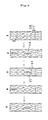
- Step 1 there is illustrated a state where an air bubble (14) begins to occur at the right/upper position of the network structure of x-shaped meshes.
- Step 2 illustrates a state where 0.3 second has lapsed from Step 1. In this state, that air bubble becomes large and resultantly the vortex enlarges.
- Step 3 illustrates a state where 0.3 second has further lapsed from Step 2. In this state, that vortex exfoliates and flows away to the back side. Simultaneously with this, it has been observed that a vortex (15) occurs at the right/lower position of the network structure of x-shaped meshes. In Step 4, this vortex enlarges and in Step 5 that vortex exfoliates.
- the width was 1 m
- the angle of the groove was 15 degrees
- the width of the groove was 2 mm
- the depth thereof was 1 mm
- the clearance between the network structure of x-shaped meshes and the surface having no such network structure was made 0.5 mm.
- a stable fluid film is formed from the opening of ejection over a long distance with the slit fluid jet being not broken in the mid-course of it.
Landscapes
- Engineering & Computer Science (AREA)
- Chemical & Material Sciences (AREA)
- Combustion & Propulsion (AREA)
- Mechanical Engineering (AREA)
- General Engineering & Computer Science (AREA)
- Nozzles (AREA)
Abstract
A method and device for forming a fluid film stably
over a long distance from a nozzle without breaking a
slit fluid jet by allowing fluid flow out from a slit to
form a slit fluid jet, superimposing a crossed flow
causing a flip-flop phenomenon upon the slit fluid jet,
and making the energy of the fluctuation velocity
component of the slit fluid jet be absorbed into the
vibration component of a flip-flop crossed flow so as to
form a stable fluid film.
Description
The invention of this application relates to a
method of stabilizing a slit fluid jet and a device
therefor. More particularly, the invention of this
application concerns a method of stabilizing a slit
fluid jet and a device therefor which are useful,
especially for preventing fluid and solid from entering
into a space of control from outside it, or for
preventing fluid and solid from going out from the space
of control into outside it.
In a prescribed space of control of a building
structure, a mechanical apparatus, etc., a slit fluid
jet has hitherto been used as means for preventing fluid
and solid from entering into the space of control from
outside it, or for preventing fluid and solid from going
out from the space of control into outside it.
For example, in a general type of building
structure, an air curtain that is a kind of slit fluid
jet is ejected at each of the inlet and outlet thereof
to thereby make effective the zoning between the space
of control and the external air, thereby the air-conditioning
efficiency is successfully enhanced.
Also, in a processing apparatus for frozen food,
air curtains are ejected from the surroundings of a
processing part thereof, to thereby form a space of cool
air for the low-temperature preservation of foodstuff.
Further, in a machine tool, liquid curtains or
shower curtains are ejected from the surroundings of a
machining part thereof, to thereby prevent cut shavings
from being scattered, or splashing out, from the space
of machining. And this slit fluid jet such as the air
curtain, liquid curtain, or shower curtain is formed by
ejecting fluid from an apparatus using a pair of smooth
flat surfaces or curved surfaces or an apparatus wherein
the nozzles are arrayed.
However, although the above-described slit fluid
jet has greatly contributed to forming the space of
control, has a lot of problems from the viewpoint of
efficiently forming a large space of control.
Namely, to form a large space of control through
the use of such slit fluid jet, it is necessary to
increase the velocity of that slit fluid jet. However,
generally, increasing the velocity of the fluid results
in that the instability of the film of the fluid
increases. This raises the problem that the filmy fluid
of the slit fluid jet becomes likely to be broken.
This likeliness to break of the fluid film of the
slit fluid jet is attributable to the turbulence
component (variable speed component) the fluid has.
This turbulence component causes the exfoliation of the
shearing layer on the inner wall of the slit, the
creation of the exfoliation vortexes, the entrapment of
air at the outlet of the slit, etc. It thereby makes
the thickness of the fluid film of the slit fluid jet
uneven, with the result that the fluid film becomes
broken due even to a small intensity of disturbance.
On this account, as one of the countermeasures
against this, it is thought to be available to decrease
the velocity of the slit fluid jet to thereby stabilize
the film of the fluid. However, making the velocity of
the fluid low results in that the fluid film is broken
even by a small intensity of disturbance.
Also, further, the above-described likeliness to
break of the fluid film becomes serious as the distance
as measured from the slit opening increases. Namely, as
the distance from the slit opening increases, the
thickness of the slit fluid jet becomes very small, so
that it is easily broken due even to a very small
magnitude of disturbance.
In order to take measures toward the problem of the
above-described likeliness to break of the fluid film,
nowadays, in general, making thick the fluid film of the
slit fluid jet is done. However, this means increasing
the flow rate of the slit fluid jet but this becomes a
factor causing a rise in the running cost.
Whereupon, the invention of this application has
been made in view of the shortcomings of the
conventional techniques mentioned above, and an object
of the present invention is to provide a method of
stabilizing a slit fluid jet and a device therefor which
enable a stable fluid film to be formed from the
ejection opening of the slit over a long distance with
that slit fluid jet being not broken.
The invention of this application, as means for
solving the above-described problems, first, provides a
method of stabilizing a slit fluid jet, comprising
superimposing a fluid jet accompanied with a flip-flop
phenomenon upon one, or both, of the surfaces of a slit
fluid jet and thereby forming a stable said slit fluid
jet.
Further, the invention of this application,
secondly, provides a stabilizing device for stabilizing
a slit fluid jet, the stabilizing device being adapted
to stabilize the slit fluid jet, comprising being
equipped with two flat plates that oppose each other
with a prescribed gap in between, one of the flat plates
of the slit having an opposing surface that is smooth,
the other having a network structure that has a
plurality of crossed grooves that are crossed like a
letter x. It, thirdly, provides a stabilizing device
for stabilizing the slit fluid jet, wherein at an outlet
of the fluid there are disposed flow passages of the
network structure so that the fluids may be merged in.
And it, fourthly, provides a stabilizing device for
stabilizing the slit fluid jet, wherein the length
between a detached vortex, occurring at the back of the
crossed groove portion, and a point to that the detached
vortex has been shifted is equal to or greater than the
length of one side of a diamond-shaped protruding
portion that is formed by the x-shaped grooves.
It is to be noted that the symbols in the figures
represent the following.
- 10
- flat plate
- 11
- crossed groove
- 12
- buffer region
- 13
- fluid supply pipe
- 14
- air bubbles
- 15
- vortex
Generally saying, the instability of the fluid film
is attributable to the turbulence of the flow, i.e. the
variable speed component. A fluid necessarily contains
this variable speed component. Therefore, extreme
difficulties are encountered in eliminating that
turbulence.
On that account, the invention of this application
has performed hydrodynamic control with respect to the
conventional simple slit fluid jet. More specifically,
the invention of this application, in order to make
uniform the non-uniformity of the fluid film thickness
that results from the turbulence of the fluid, has
formed a fluid film that has a two-layer structure of a
slit fluid jet flow and a flip-flop flow. The invention
of this application has resultantly added a mechanism
for absorbing, with the lapse of time, the variable
speed component that is contained in the slit fluid jet
flow. In this respect, the invention of this
application has a great characterizing feature.
In the process of reaching the present invention,
the inventors of this application have initially thought
that, if a phenomenon peculiar to a fluid that occurs
utilizing the variable speed in it as the energy of it
is superimposed upon the slit fluid jet flow, a stable
fluid film will be formed. Based on this idea, the
inventors of this application has conceived the fact
that a detached vortex, which appears in the flow at the
back of a substance and which is typically represented
by a Karman vortex, periodically occurs due to the
existence of the variable speed component.
Namely, when a substance has flow passages that
have been disposed in a zigzag way, at each of the
crossed portions thereof there occurs the flip-flop
phenomenon that periodic vibrations occur in the radial
direction of the flow. This flip-flop phenomenon is the
mechanism for absorbing the variable speed component
with the lapse of time, and that that flip-flop
phenomenon is known as converting that variable speed
component to the periodic vibrations that occur in the
radial direction of the main flow.
And, the inventors of this application have applied
that flip-flop phenomenon to actual stabilizing of the
slit fluid jet flow, and have thereby come to the
present invention.
Regarding the method of stabilizing the slit fluid
jet flow according to the present invention, more
specifically, if causing a fluid to be ejected from the
slit opening to thereby form a slit fluid jet,
superimposing a crossed flow, which is followed by the
flip-flop phenomenon, upon this slit flow jet, and
thereby causing the variable speed component energy of
the slit fluid jet to be absorbed into the vibration
component of the flip-flop crossed flow, a stable fluid
film is formed. The flip-flop crossed flow is formed by
means of a network terminal formed by a plurality of
crossed grooves and causes the jet flow to periodically
vibrate in the radial direction of it. This periodic
vibration is caused by the flow of the fluid and this
periodic vibration is amplified by the interaction
between the ejected pieces of flow. This groove flow
structure that is constructed of a plurality of groove
flows acts to convert the turbulent component of the
fluid into the periodic vibration component that is
active in the radial direction of it.
Namely, the network structure that is comprised of
the flow passages formed by the grooves controls the
turbulent component of the fluid, and causes the flip-flop
phenomenon to occur at each of the points of
merging of the groove flows and causes each of the
groove flows to periodically vibrate in the radial
direction of the groove.
The slit fluid jet upon which this flip-flop
crossed flow is superimposed becomes stabilized. This
is because, if the jet flow followed by the flip-flop
phenomenon exists on any one surface of the liquid film
of the slit fluid jet, the component of fluctuation of
the slit fluid jet is converted into the flip-flop
phenomenon energy that is active upon that jet.
A device for stabilizing the slit fluid jet
according to the present invention includes, as an
aspect, the one that has been illustrated in Fig. 1.
This stabilizing device for the slit fluid jet is
constructed of two flat plates (10) that oppose each
other with a prescribed spacing in between. The inside
of one of those flat plates is smooth while the other
thereof has a network structure that has a plurality of
crossed grooves (11) the configuration of that is shaped
like a letter x.
And, preferably, the flow passages of the network
structure are located so that the pieces of fluid may
merge in the flow-out opening of the fluid, and it is
preferable that the distance from a detached vortex
appearing at the back of each of the crossed portions to
the point to which that detached vortex has been shifted
be equal to or greater than one side of the diamond-shaped
protruding portion formed by the x-shaped
grooves.
Incidentally, although it is preferable that the
flat plates (10) be flat surface members, they may be
curved surface members. In that case, that the
clearance that is the gap between the opposing members
be equal, preferably, is made the requirement.
Also, a buffer region (12) for the fluid may be
formed at one side of the clearance. The fluid that has
been supplied from a fluid supply pipe (13) is allowed
to flow between the paired opposing members, and this
fluid is ejected as a slit fluid jet.
Fig. 2 is a view illustrating, as a plan view, the
member inside the slit that has a network structure.
This member has provided therein as the passages of
fluid a plurality of grooves 1a, b, c, ..., n and a
plurality of grooves 2a, b, c, ..., n in the way both
form net meshes. The respective ones of the grooves 1a,
b, c, ..., n are provided at equal intervals and in
parallel with one another, and the respective ones of
the grooves 2a, b, c, ..., n are also provided in the
same way.
A plurality of grooves that are included in the
angular region (A) defined between the flow and the main
axis and a plurality of grooves that are included in the
angular region (-A) that has been similarly defined are
provided each in paired relationship with each other so
that the pieces of fluid may merge together to go out
from the ejection opening. Namely, they are provided so
that the fluid that has been supplied from an inlet
portion (IL) of the fluid may merge together at an
outlet portion (OL). As a result of this, they make
out, at the merging portion, the fluid jet having the
periodic vibration component that is active in the right
and left direction of the drawing sheet.
In Fig. 3, since the fluid is being supplied under
a prescribed pressure from the buffer region, the fluid
flows into the groove 1a as a fluid jet L1a and the
fluid flows from the groove 1b as a fluid jet L1b. And
the two pieces of liquid flow merge at a crossed passage
M1. As a result of this merging, the flow speed is
accelerated, whereby at this crossed portion there is a
point of energy supply where the flow speed is maximum
and the pressure is minimum. At the back of that
crossed portion, there are formed asymmetrical detached
vortexes. These asymmetrical detached vortexes at the
back of that crossed portion are affected by the point
of energy supply and, with the lapse of time, their
position and shape are changed, whereby those asymmetric
detached vortexes alternately appear at the positions of
V1 and V2 (see Fig. 4 too). The period in which they
alternately appear depends upon the Strouhal number that
is almost in inverse proportion to the Reynolds number.
A further explanation will now be given of the
details of the flip-flop phenomenon that is the
important basic principle of the present invention.
This flip-flop phenomenon is based on the
utilization of the fact that the speed fluctuation at
the back flow of a substance has periodicity. For
example, when there is a substance in the course of the
flow whose speed is V, the vortexes that mutually rotate
in opposite directions alternately occur from that
substance and flows backward. For this reason,
periodicity occurs in the fluctuation of speed in the
back flow of the substance. The frequency at which
those vortexes occur is given by the dimensionless
Strouhal number St = f L/V, where the f represents the
frequency in the periodic fluctuation phenomenon of the
fluid; L represents the projection length of the
substance toward the surface vertical to the flow (in
general the significant length of the substance
configuration. If that substance is a circular columnar
member, the diameter of it); and V represents the speed
of the fluid. For example, that the electric wire is
sounded cracked on the strong wind of day is the
phenomenon that that vortex is released.
In general, the Strouhal number depends upon the
configuration of the substance. In the case of, for
example, a circular columnar member, it is known that
when the Reynolds number is from 1,000 to 100,000, the
Strouhal number is 0.2.
In the natural world, there is a living being that
well utilizes the nature that periodicity exists in the
vortexes at the back flow of a substance. Lighthill
describes in his "Mathematical Biofluid Mechanics"
(Society for Industrial and Applied Mathematics, 1975),
as follows. A group of fishes that takes a network
structure of x-shaped meshes, which while being situated
at a diagonal position are swimming at the back of fish,
tends to decrease the resistance applied to that group
of forwardly moving fishes through the use of the
periodic vortex flows that are released from the fish
that is going ahead.
Especially, the positional relationship in the
network structure of x-shaped meshes acts to make the
vortexes keep having their periodicity, while making the
energy thereof keep increased. Accordingly, it is
thought that the network structure of x-shaped meshes,
which is formed by a plurality of crossed grooves, will
be useful, from the viewpoint of such a natural
phenomenon as well.
Next, using Fig. 4, an explanation will be given of
the flip-flop phenomenon that occurs in the flow in the
network structure of x-shaped meshes. In Step 1, there
is illustrated a state where an air bubble (14) begins
to occur at the right/upper position of the network
structure of x-shaped meshes. Step 2 illustrates a
state where 0.3 second has lapsed from Step 1. In this
state, that air bubble becomes large and resultantly the
vortex enlarges. Step 3 illustrates a state where 0.3
second has further lapsed from Step 2. In this state,
that vortex exfoliates and flows away to the back side.
Simultaneously with this, it has been observed that a
vortex (15) occurs at the right/lower position of the
network structure of x-shaped meshes. In Step 4, this
vortex enlarges and in Step 5 that vortex exfoliates.
In that way, the exfoliation of vortex periodically
occurs to thereby cause the occurrence of the flip-flop
phenomenon that vertically vibrates the jet flow at the
backward opening of ejection.
Also, in the flows in the interiors of the network
grooves that are formed by a plurality of the crossed
grooves, not only the periodic vibration phenomena of
the jet flow that occur at the network terminal but also
the interaction between the pieces of ejection of the
fluid occur in various ways. That interaction includes,
for example, the appearance of the Lamb effect (the
ultrasonic vibrations appearing on the surface of a
small-thickness solid), the vibration phenomenon of a
shear layer caused to appear due to the conflict between
the pieces of flow, the attraction characteristic
appearing due to the detached vortexes, and the Coanda
effect.
Hereinafter, an embodiment of the present invention
will be shown below and the invention will be explained
in more detail.
Using actually the stabilizing device for a slit
fluid jet according to the present invention, a slit
fluid jet was formed and its behavior was observed.
In this device, the width was 1 m, the angle of the
groove was 15 degrees, the width of the groove was 2 mm,
the depth thereof was 1 mm, and the clearance between
the network structure of x-shaped meshes and the surface
having no such network structure was made 0.5 mm.
When water was jetted from the slit at a flow speed
of 0.5 m/s, a stable film of water with no broken
portion existing therein was formed over a length of
1000 mm. In addition, the thickness of that water film
on an upstream side thereof was substantially the same
as that of it on a downstream side thereof. The amount
of water at that time was 30 liter/min.
On the other hand, regarding an ordinary slit fluid
jet having no network structure, experiments were
conducted with the flow rate being made the same. As a
result, breakage occurred at the position in the
vicinity of 20 mm and, at the same time, the thickness
of the water film became extremely great toward the
downstream side of it. To make the stable liquid film
keep extending up to a position 1000 mm downstream of it
when it was prepared from the ordinary slit fluid jet,
an amount of water of 200 liter/min. was needed.
Using air, the same experiment as in the case of
water was conducted at the flow speed of 5 m/s. The
resulting air jet was visualized using an argon laser
sheet. In the case of the ordinary slit fluid jet, a
breakage phenomenon occurred at a position 15 mm
downstream of the film, whereas, in the case of the slit
fluid jet flow ejected from the invention of this
application, a stable air film was formed up to a
position 650 mm downstream of it.
As has been explained above in detail, according to
the invention of this application, a stable fluid film
is formed from the opening of ejection over a long
distance with the slit fluid jet being not broken in the
mid-course of it.
Claims (4)
- A method of stabilizing a slit fluid jet, comprising superimposing a fluid jet accompanied with a flip-flop phenomenon upon one, or both, of the surfaces of a slit fluid jet and thereby forming a stable said slit fluid jet.
- A stabilizing device for stabilizing a slit fluid jet, the stabilizing device being adapted to stabilize a slit fluid jet as in claim 1, comprising two flat plates that oppose each other with a prescribed gap in between, one of the flat plates of the slit having an opposing surface that is smooth, the other having a network structure that has a plurality of crossed grooves that are crossed like a letter x.
- A stabilizing device for stabilizing a slit fluid jet according to claim 2, wherein at an outlet of the fluid there are disposed flow passages of the network structure so that the fluids may be merged in.
- A stabilizing device for stabilizing a slit fluid jet according to claim 2 or 3, wherein the length between a detached vortex, occurring at the back of the crossed groove portion, and a point to which the detached vortex has been shifted is equal to or greater than the length of one side of a diamond-shaped protruding portion that is formed by the x-shaped grooves.
Applications Claiming Priority (1)
| Application Number | Priority Date | Filing Date | Title |
|---|---|---|---|
| PCT/JP2000/002776 WO2001084059A1 (en) | 2000-04-27 | 2000-04-27 | Method and device for stabilizing slit fluid jet |
Publications (2)
| Publication Number | Publication Date |
|---|---|
| EP1278024A1 true EP1278024A1 (en) | 2003-01-22 |
| EP1278024A4 EP1278024A4 (en) | 2005-11-23 |
Family
ID=11735979
Family Applications (1)
| Application Number | Title | Priority Date | Filing Date |
|---|---|---|---|
| EP00922894A Withdrawn EP1278024A4 (en) | 2000-04-27 | 2000-04-27 | Method and device for stabilizing slit fluid jet |
Country Status (4)
| Country | Link |
|---|---|
| US (1) | US6883734B1 (en) |
| EP (1) | EP1278024A4 (en) |
| CA (1) | CA2381061A1 (en) |
| WO (1) | WO2001084059A1 (en) |
Cited By (2)
| Publication number | Priority date | Publication date | Assignee | Title |
|---|---|---|---|---|
| NL1036489C2 (en) * | 2009-01-30 | 2010-08-02 | Biddle B V | AIR CURTAIN DEVICE AND METHOD WITH A PULSING AIRFLOW. |
| AT512815A1 (en) * | 2012-04-27 | 2013-11-15 | Karl Stefan Riener | Air guiding device for a heating device |
Families Citing this family (3)
| Publication number | Priority date | Publication date | Assignee | Title |
|---|---|---|---|---|
| CA2832494C (en) * | 2011-04-06 | 2019-11-26 | Ortho-Clinical Diagnostics, Inc. | Assay device having rhombus-shaped projections |
| CN104321540B (en) | 2012-04-04 | 2016-11-02 | 全面熔合有限公司 | Jet vectoring Apparatus and method for |
| CN116241603B (en) * | 2023-04-11 | 2025-07-22 | 哈尔滨工业大学 | Double-synthetic jet vibration damping protection device with cylindrical structure |
Family Cites Families (6)
| Publication number | Priority date | Publication date | Assignee | Title |
|---|---|---|---|---|
| JPS5417650U (en) * | 1978-07-17 | 1979-02-05 | ||
| US4662568A (en) * | 1982-09-28 | 1987-05-05 | Peter Bauer | Jet break-up device for spray nozzle applications |
| JPH068887B2 (en) * | 1988-10-27 | 1994-02-02 | 中国電力株式会社 | Opening shielding device |
| IL107120A (en) * | 1992-09-29 | 1997-09-30 | Boehringer Ingelheim Int | Atomising nozzle and filter and spray generating device |
| NL9300305A (en) * | 1993-02-17 | 1994-09-16 | Biddle F H Bv | Air curtain with flow control. |
| US6127571A (en) * | 1997-11-11 | 2000-10-03 | Uop Llc | Controlled reactant injection with permeable plates |
-
2000
- 2000-04-27 CA CA002381061A patent/CA2381061A1/en not_active Abandoned
- 2000-04-27 WO PCT/JP2000/002776 patent/WO2001084059A1/en not_active Ceased
- 2000-04-27 EP EP00922894A patent/EP1278024A4/en not_active Withdrawn
- 2000-04-27 US US10/031,597 patent/US6883734B1/en not_active Expired - Fee Related
Cited By (2)
| Publication number | Priority date | Publication date | Assignee | Title |
|---|---|---|---|---|
| NL1036489C2 (en) * | 2009-01-30 | 2010-08-02 | Biddle B V | AIR CURTAIN DEVICE AND METHOD WITH A PULSING AIRFLOW. |
| AT512815A1 (en) * | 2012-04-27 | 2013-11-15 | Karl Stefan Riener | Air guiding device for a heating device |
Also Published As
| Publication number | Publication date |
|---|---|
| EP1278024A4 (en) | 2005-11-23 |
| US6883734B1 (en) | 2005-04-26 |
| CA2381061A1 (en) | 2001-08-11 |
| WO2001084059A1 (en) | 2001-11-08 |
Similar Documents
| Publication | Publication Date | Title |
|---|---|---|
| JPH0443712B2 (en) | ||
| CN108024669B (en) | Spitting device | |
| JP2003507681A (en) | Instrument for guiding force by fluid injection | |
| Tamburrino et al. | Large flow structures in a turbulent open channel flow | |
| JP2017080721A (en) | Ultrafine bubble generating tool | |
| Chanson et al. | Air entrainment by two-dimensional plunging jets: the impingement region and the very-near flow field | |
| Narendran et al. | Effect of near-wake jet on the lock-in of a freely vibrating square cylinder | |
| US20160061385A1 (en) | Passive diode-like device for fluids | |
| US5803602A (en) | Fluid mixing device with vortex generators | |
| US6883734B1 (en) | Method and device for stabilizing slit fluid jet | |
| Prince et al. | On jet impingement and thin film breakup on a horizontal superhydrophobic surface | |
| JP4824190B2 (en) | Turbulent friction resistance reduction surface | |
| SE445326B (en) | SET AND DEVICE FOR THE PREVENTION OF WALL TURNS | |
| JP2005334869A (en) | Method and apparatus for micro bubble generation | |
| JP4309981B2 (en) | Slit fluid jet stabilization method and apparatus | |
| JP2007144394A (en) | Bubble generator | |
| BR112020009405B1 (en) | MULTILOBULAR SUPERSONIC GAS NOZZLES FOR LIQUID SPRAYING | |
| Kate et al. | Hydraulic jumps with corners due to obliquely inclined circular liquid jets | |
| US6349734B1 (en) | Method for reducing dissipation rate of fluid ejected into boundary layer | |
| JP5567796B2 (en) | Fluid ejection device | |
| US12220714B2 (en) | Double-sided fluidic oscillator jet | |
| Sigurdson | The structure and control of a turbulent reattaching flow | |
| Li et al. | The flow past a sphere with centric cylindrical bore of different diameter and orientation | |
| Olaru | The fluid flow simulation through to a Venturi nozzle | |
| JP2007229674A (en) | Microbubble and micromist generator |
Legal Events
| Date | Code | Title | Description |
|---|---|---|---|
| PUAI | Public reference made under article 153(3) epc to a published international application that has entered the european phase |
Free format text: ORIGINAL CODE: 0009012 |
|
| 17P | Request for examination filed |
Effective date: 20020326 |
|
| AK | Designated contracting states |
Kind code of ref document: A1 Designated state(s): AT BE CH CY DE DK ES FI FR GB GR IE IT LI LU MC NL PT SE |
|
| RBV | Designated contracting states (corrected) |
Designated state(s): AT BE CH CY DE ES FR GB IT LI |
|
| A4 | Supplementary search report drawn up and despatched |
Effective date: 20051007 |
|
| STAA | Information on the status of an ep patent application or granted ep patent |
Free format text: STATUS: THE APPLICATION IS DEEMED TO BE WITHDRAWN |
|
| 18D | Application deemed to be withdrawn |
Effective date: 20051221 |