EP1277994A2 - Head gasket - Google Patents
Head gasket Download PDFInfo
- Publication number
- EP1277994A2 EP1277994A2 EP02015546A EP02015546A EP1277994A2 EP 1277994 A2 EP1277994 A2 EP 1277994A2 EP 02015546 A EP02015546 A EP 02015546A EP 02015546 A EP02015546 A EP 02015546A EP 1277994 A2 EP1277994 A2 EP 1277994A2
- Authority
- EP
- European Patent Office
- Prior art keywords
- hole
- head gasket
- base plate
- gasket
- sealing
- Prior art date
- Legal status (The legal status is an assumption and is not a legal conclusion. Google has not performed a legal analysis and makes no representation as to the accuracy of the status listed.)
- Granted
Links
Images

Classifications
-
- F—MECHANICAL ENGINEERING; LIGHTING; HEATING; WEAPONS; BLASTING
- F02—COMBUSTION ENGINES; HOT-GAS OR COMBUSTION-PRODUCT ENGINE PLANTS
- F02F—CYLINDERS, PISTONS OR CASINGS, FOR COMBUSTION ENGINES; ARRANGEMENTS OF SEALINGS IN COMBUSTION ENGINES
- F02F11/00—Arrangements of sealings in combustion engines
-
- F—MECHANICAL ENGINEERING; LIGHTING; HEATING; WEAPONS; BLASTING
- F16—ENGINEERING ELEMENTS AND UNITS; GENERAL MEASURES FOR PRODUCING AND MAINTAINING EFFECTIVE FUNCTIONING OF MACHINES OR INSTALLATIONS; THERMAL INSULATION IN GENERAL
- F16J—PISTONS; CYLINDERS; SEALINGS
- F16J15/00—Sealings
- F16J15/02—Sealings between relatively-stationary surfaces
- F16J15/06—Sealings between relatively-stationary surfaces with solid packing compressed between sealing surfaces
- F16J15/08—Sealings between relatively-stationary surfaces with solid packing compressed between sealing surfaces with exclusively metal packing
- F16J15/0818—Flat gaskets
-
- F—MECHANICAL ENGINEERING; LIGHTING; HEATING; WEAPONS; BLASTING
- F16—ENGINEERING ELEMENTS AND UNITS; GENERAL MEASURES FOR PRODUCING AND MAINTAINING EFFECTIVE FUNCTIONING OF MACHINES OR INSTALLATIONS; THERMAL INSULATION IN GENERAL
- F16J—PISTONS; CYLINDERS; SEALINGS
- F16J15/00—Sealings
- F16J15/02—Sealings between relatively-stationary surfaces
- F16J15/06—Sealings between relatively-stationary surfaces with solid packing compressed between sealing surfaces
- F16J15/08—Sealings between relatively-stationary surfaces with solid packing compressed between sealing surfaces with exclusively metal packing
- F16J15/0818—Flat gaskets
- F16J2015/0868—Aspects not related to the edges of the gasket
-
- F—MECHANICAL ENGINEERING; LIGHTING; HEATING; WEAPONS; BLASTING
- F16—ENGINEERING ELEMENTS AND UNITS; GENERAL MEASURES FOR PRODUCING AND MAINTAINING EFFECTIVE FUNCTIONING OF MACHINES OR INSTALLATIONS; THERMAL INSULATION IN GENERAL
- F16J—PISTONS; CYLINDERS; SEALINGS
- F16J15/00—Sealings
- F16J15/02—Sealings between relatively-stationary surfaces
- F16J15/06—Sealings between relatively-stationary surfaces with solid packing compressed between sealing surfaces
- F16J15/08—Sealings between relatively-stationary surfaces with solid packing compressed between sealing surfaces with exclusively metal packing
- F16J15/0818—Flat gaskets
- F16J2015/0875—Flat gaskets comprising welds
Definitions
- the invention relates to a head gasket to be installed between two engine members, such as a cylinder head and a cylinder block, to seal therebetween.
- the present invention relates to a head gasket having high sealing ability and good durability even in an area outside an area surrounded by bolt holes or bolts for tightening the cylinder head and the cylinder block.
- a head gasket is installed therebetween to thereby seal combustion gas.
- the head gasket has been changed to a metal gasket having a simple structure of one or two metal plates from a laminate type gasket having a plurality of metal plates. Since the number of the constituting plates is reduced, the material to be used has been limited.
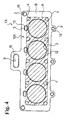
- the head gasket as shown in Fig. 4, is formed in conformity with a shape of an engine member, such as a cylinder block, and provided with holes 2 for the cylinder bores (hereinafter referred to simply as “cylinder bore"), liquid holes 3 for circulating cooling water and engine oil (hereinafter referred to simply as “liquid hole”), holes 4 for the bolts (hereinafter referred to simply as “bolt hole”) and the like. Then, beads 12, 13 as the sealing devices are disposed around the holes 2, 3 to be sealed, respectively.
- the base plate for sealing that portion is made of an annealed stainless material or soft steel material excellent in heat resistance and the bending ability.
- a bead 12 capable of coping with the high temperature and high pressure, and having a good elasticity with a circular arc shape and a narrow width, which provides a good follow-up ability with respect to changes of spaces.
- the cylinder bore 2 is surrounded by the bolt holes 4 for tightening the cylinder head and the cylinder block with the bolts to thereby obtain a large surface pressure by the tightening force.
- the portion for sealing the liquid hole 3 disposed in the area B outside the area A is made of the same metal material as that of the base plate for making a normal gasket, the follow-up ability with respect to the changes of the space becomes poor even if the shape of the bead is specially designed for it. Also, in case the gasket receives a great change, the gasket is liable to be subjected to creep relaxation. Thus, there has been a problem such that the sealing ability and durability with respect to the liquid holes 3 are not sufficient.
- a material excellent in heat resistance and bending ability such as annealed stainless material and soft steel material, is preferable.
- a material capable of following up the change with an appropriate elasticity such as a spring steel material, is preferable.
- a spring steel material is preferable in the area B outside the area A surrounded by the bolt holes 4, it is preferable to use the spring steel material.
- an object of the invention is to provide a head gasket having a thin plate structure, wherein in case joint surfaces of a cylinder head and a cylinder block of an engine are sealed by a metal head gasket, a cylinder bore in an area surrounded by bolt holes and a liquid hole disposed outside the area are both sealed by optimum metal materials, respectively, to thereby provide a head gasket having a good sealing ability and durability.
- a head gasket according to the present invention seals between a cylinder head and a cylinder block of an engine, and a base plate of the head gasket is generally made of a first metal material, such as annealed stainless material or soft steel material.
- a circumferential member made of a second metal material, such as a spring steel material is disposed to a portion for sealing a liquid hole formed in an area outside the area surrounded by the bolt holes for tightening the cylinder head and the cylinder block by bolts, and a bead surrounding the liquid hole is provided on the circumferential member.
- the circumferential member is integrally joined to the base plate.
- a Vickers hardness of the first metal material is in a range of 70 - 200, and a Vickers hardness of the second metal material is in a range of 300 to 600.
- the circumferential member and the base plate are linearly integrated by the laser welding.
- the first metal material for constituting the base plate there are considered an annealed stainless material, soft steel material and the like having a small Vickers hardness, good heat resistance and bending ability
- the second metal material for constituting the circumferential member there are considered a spring steel material and the like having a large Vickers hardness and good elasticity.
- a combination of an annealed stainless material or soft steel material and a spring steel material is most preferable.
- the base plate for sealing the cylinder bores and covering portions compressed by the tightening bolts is made of the first metal material, such as annealed stainless material or soft steel material, having a Vickers hardness of 70 - 200, good sealing ability with respect to the cylinder bores and good fitness with the cylinder head, cylinder block and the like can be obtained.
- the first metal material such as annealed stainless material or soft steel material, having a Vickers hardness of 70 - 200
- the circumferential member for sealing the liquid holes disposed on the area outside the area surrounded by the bolt holes is made of the second metal material, such as the spring steel material, having the Vickers hardness of 300 - 600, preferably 350 - 450, even in the outside area where the change of space between the cylinder head and the cylinder block becomes large due to a vibration caused by the cooling-heating temperature cycle at the time of operation of the engine, the follow-up ability due to the elasticity of the second metal material is improved.
- the sealing ability and durability with respect to the liquid holes disposed on the area outside the area surrounded by the bolt holes can be improved.
- spot welding margins may be provided on the end portions of the circumferential member and the base plate, respectively, and the spot welding margins may be partially overlapped with each other and spot-welded.
- a joining portion is formed in a linear shape by the laser welding.
- the weight of the head gasket can be reduced as well as the material thereof is saved. Further, by welding the circumferential member and the base plate in the linear shape, the joining strength can be extremely improved when compared with the spot welding, so that even in case the vibration is relatively large and the circumferential member is supported only by one side, the fatigue failure is hard to occur.
- the above described structure according to the present invention is especially effective when the number of the base plate of the metal gasket is one.
- the number of the base plates is plural or the number of the base plates is more than two, i.e. a metal laminate gasket includes an intermediate plate, i.e. more than two, good effect can be obtained.
- the difference between the elastic coefficients of the base plate and the circumferential member may be made by the heat treatment process by locally carrying out a heat treatment, in addition to the joint of different metal materials.
- a head gasket 1 of an embodiment according to the present invention is a metal gasket to be installed between a cylinder head and a cylinder block (not shown) of an engine to seal combustion gas of high temperature and high pressure in a cylinder bore, and a liquid, such as cooling water and oil, passing through a cooling water path and a cooling oil path.
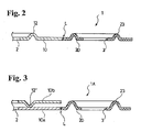
- FIGs. 2 and 3 are explanatory schematic views, wherein a plate thickness, dimensions of a bead and a sealing groove and a ratio of length to width of the metal gasket are different from those actually measured to emphasize a sealing portion to thereby facilitate understanding thereof.
- the head gasket 1 of the first embodiment according to the present invention is formed of a single constituting plate, and the constituting plate is formed of a base plate 10 and circumferential members 20 integrally joined thereto.
- the base plate 10 is a member to cover a portion including an area A surrounded by the bolt holes 4 for bolts for tightening the cylinder head and the cylinder block, and is made of a first metal material, such as an annealed stainless material and soft steel material, having a high heat resistance and bending ability, with a Vickers hardness of 70 - 200.
- a first metal material such as an annealed stainless material and soft steel material, having a high heat resistance and bending ability, with a Vickers hardness of 70 - 200.
- the base plate 10 is provided with sealing devices, such as beads 12, for cylinder bores 2, and also sealing devices, such as beads 13, for cooling water and oil in the area covered by the base plate 10.
- the outer circumferential members 20 are members for covering portions of an area B outside the area A surrounded by the bolt holes 4.
- the circumferential member 20 is made of a second metal material having an appropriate elasticity, such as a Vickers hardness of 300 - 600, preferably 350 - 450, of a spring steel material or the like.
- the liquid hole 3 disposed in an area covered by the circumferential member 20 is sealed by a bead 23, such as a full bead and a half bead, surrounding the liquid hole 3.
- the circumferential member 20 is integrally welded with the base plate 10 by laser beam in a linear shape L.
- Fig. 1 shows an example of an arrangement of the base plate 10 and the circumferential members 20, wherein the base plate 10 is formed to completely cover the area A surrounded by the bolt holes 4, and the circumferential members 20 are formed to cover at least parts of the area B outside the area A.
- the areas that the circumferential members 20 cover are determined by considering the sealing abilities and the like required for the liquid holes 3 disposed in the area B.
- the thickness of the base plate 10 is 0.2 - 1.0 mm
- the height of the bead 12 for the cylinder bore 2 is 0.2 - 0.3 mm
- the thickness of the circumferential member is 0.2 - 0.1 mm
- the height of the bead 23 for the liquid hole 3 is 0.2 - 0.4 mm.
- the first metal material for forming the base plate 10 and the second metal material for forming the circumferential members 20 are different.
- the second metal material is a spring material, the respective holes 2, 3 to be sealed disposed in the respective areas can be sealed by the materials suitable therefor. Therefore, the head gasket 1 having a good sealing ability and durability can be obtained.
- the weight of the head gasket 1 can be lightened, and the materials can be saved.
- the head gasket 1A is made of two base plates 10a, 10b.
- the base plate 10a is similar to the head gasket 1 of the first embodiment, but the beads 12, 13 for sealing around the cylinder bores 2 and liquid holes 3 are not formed thereon. Also, the beads 23 are made higher than that of the gasket 1.
- the base plate 10b has the shape corresponding the portions where the base plate 10 extends, i.e. excluding the circumferential members 20.
- the base plate 10b has the bead 12' and other beads (not shown) to seal around the cylinder bores and liquid holes.
- the base plates 10a, 10b are laminated together to constitute the head gasket 1A.
- the head gasket 1A has the same operational effects as those of the head gasket 1.
- the base plate 10b made of one metal may have the shape exactly the same as that of the base plate 10a.
- the base plate is made of the first metal material, such as an annealed stainless material and a soft steel material
- the surrounding members are made of the second metal material, such as a spring steel material
- the base plate and the surrounding members are formed of metal materials suitable for the areas to be covered by the respective members. Therefore, good sealing abilities can be obtained for both the cylinder bore and liquid hole to thereby provide a head gasket having good durability.
- the first metal material such as annealed stainless material and soft steel material, having a high heat resistance and a deformable property with respect to the bending process can be used in an area where the combustion gas of high pressure and high temperature is required to be sealed by a strong pressing force.
- the second metal material such as spring steel material having an appropriate elasticity and good follow-up ability with respect to deformation can be used in the area, located outside the area surrounded by the bolt holes, where a pressing force is relatively small, temperature is relatively low and a space greatly changes.
- the circumferential members disposed outside the area surrounded by the bolt holes are made of the second metal material, such as the spring steel material, having good elasticity, even in the circumferential portions where a change in the space between the cylinder head and the cylinder block becomes large due to the vibration caused by operation of the engine through one side holding, the follow-up ability of the gasket with respect to the change in the space can be improved, and the sealing ability with respect to the liquid holes disposed on the circumferential portion can be improved.
- the durability can also be improved.
- the joint between the circumferential members and the base plate is carried out by the laser welding in the linear shape, the overlapped portion between the circumferential member and the base plate can be eliminated to thereby reduce the weight of the head gasket and save the materials. Further, since the joining strength can be extremely improved through welding in the linear shape, it is possible to prevent the fatigue failure even in the area, outside the area surrounded by the bolt holes, where vibration is relatively large.
Landscapes
- Engineering & Computer Science (AREA)
- General Engineering & Computer Science (AREA)
- Mechanical Engineering (AREA)
- Chemical & Material Sciences (AREA)
- Combustion & Propulsion (AREA)
- Gasket Seals (AREA)
Abstract
Description
Claims (7)
- A head gasket (1, 1A) for an internal combustion engine having at least one cylinder bore, bolt holes and at least: one liquid hole, comprising:a base plate having at least one first hole (2) corresponding to the at least one cylinder bore, second holes (4) corresponding to the bolt holes and surrounding the at least one first hole, an outer area (B) outside imaginary lines linking the second holes outside the at least one first hole, and at least one third hole (3) corresponding to the at least one liquid hole and located in the outer area, andat least one bead (23) formed on the second portion (B) outside the at least one third hole for sealing the at least one third hole,said head gasket being characterized in that said base plate includes a first portion (10, 10a) covering at least an area inside the outer area including the first and second holes (2, 4) and being made of a material selected from the group consisting of annealed stainless steel and soft steel, and at least one second portion (20) covering a part of the outer area including the at least one third hole (3) and being made of spring steel, said at least one second portion being integrally fixed to the first portion.
- A head gasket (1, 1A) according to claim 1, further comprising sealing means (12) formed around the at least one first hole (2) for sealing around the at least one first hole.
- A head gasket (1) according to claim 2, wherein said sealing means is a bead (12) integrally formed in the first portion.
- A head gasket (1, 1A) according to any one of claims 1 to 3, wherein said at least one second portion (20) includes only one third hole and projects outwardly from the first portion.
- A head gasket (1, 1A) according to any one of claim 1 to 4, wherein said first portion (10, 10a) has a Vickers hardness in a range of 70 - 200, and the at least one second portion (20) has a Vickers hardness in a range of 300 to 600.
- A head gasket (1, 1A) according to any one of claims 1 to 5, wherein said first and second portions (10, 10A; 20) are linearly integrated by laser welding.
- A head gasket (1A) according to any one of claims 1 to 6, further comprising an additional metal plate (10b) disposed on the base plate (10a) for constituting a metal laminate gasket.
Applications Claiming Priority (2)
| Application Number | Priority Date | Filing Date | Title |
|---|---|---|---|
| JP2001219943 | 2001-07-19 | ||
| JP2001219943A JP2003035202A (en) | 2001-07-19 | 2001-07-19 | Head gasket |
Publications (3)
| Publication Number | Publication Date |
|---|---|
| EP1277994A2 true EP1277994A2 (en) | 2003-01-22 |
| EP1277994A3 EP1277994A3 (en) | 2004-01-14 |
| EP1277994B1 EP1277994B1 (en) | 2005-09-28 |
Family
ID=19053847
Family Applications (1)
| Application Number | Title | Priority Date | Filing Date |
|---|---|---|---|
| EP02015546A Expired - Lifetime EP1277994B1 (en) | 2001-07-19 | 2002-07-11 | Head gasket |
Country Status (5)
| Country | Link |
|---|---|
| US (1) | US6779800B2 (en) |
| EP (1) | EP1277994B1 (en) |
| JP (1) | JP2003035202A (en) |
| KR (1) | KR20030009142A (en) |
| DE (1) | DE60206333T2 (en) |
Cited By (4)
| Publication number | Priority date | Publication date | Assignee | Title |
|---|---|---|---|---|
| EP1574760A1 (en) * | 2004-03-08 | 2005-09-14 | Ishikawa Gasket Co. Ltd. | Gasket |
| DE102004040784C5 (en) * | 2004-08-23 | 2016-03-03 | Reinz-Dichtungs-Gmbh | Cylinder head flat gasket with a multi-part layer |
| DE102004064109C5 (en) * | 2004-08-23 | 2019-03-21 | Reinz-Dichtungs-Gmbh | Use of a cylinder head gasket |
| DE102004064110C5 (en) * | 2004-08-23 | 2019-04-04 | Reinz-Dichtungs-Gmbh | Cylinder head gasket with a multi-part position |
Families Citing this family (11)
| Publication number | Priority date | Publication date | Assignee | Title |
|---|---|---|---|---|
| DE10306416B4 (en) * | 2003-02-15 | 2013-02-21 | Federal-Mogul Sealing Systems Gmbh | Cylinder head gasket |
| ITBO20030563A1 (en) * | 2003-09-30 | 2005-04-01 | Spal Srl | ELECTRIC MOTOR FOR ELECTRIC FAN AND ASSEMBLY METHOD OF THE SAME |
| JP2005155667A (en) * | 2003-11-20 | 2005-06-16 | Nippon Packing Kogyo Kk | Gasket |
| US20060290073A1 (en) * | 2005-06-27 | 2006-12-28 | Freudenberg-Nok General Partnership | Insertable carrier for multiple piece gasket designs that limit compression |
| EP1985896B1 (en) * | 2007-04-24 | 2012-12-12 | REINZ-Dichtungs-GmbH | Metal flat gasket |
| US7694978B2 (en) * | 2006-08-08 | 2010-04-13 | Federal-Mogul World Wide, Inc. | Gasket assembly and method of manufacture thereof |
| JP5639650B2 (en) * | 2009-08-11 | 2014-12-10 | フェデラル−モーグル コーポレイション | Static bimetal gasket and method of construction |
| US8567791B2 (en) * | 2009-10-29 | 2013-10-29 | Dana Automotive Systems Group, Llc | Multi-layer steel insert for gaskets |
| JP5995346B2 (en) * | 2012-03-15 | 2016-09-21 | 内山工業株式会社 | gasket |
| JP5913533B1 (en) * | 2014-11-13 | 2016-04-27 | 石川ガスケット株式会社 | Gasket and gasket manufacturing method |
| US9664284B2 (en) * | 2015-08-05 | 2017-05-30 | General Electric Company | Cover system with gasket system therefor |
Family Cites Families (12)
| Publication number | Priority date | Publication date | Assignee | Title |
|---|---|---|---|---|
| FR2563600B1 (en) * | 1984-04-26 | 1986-07-11 | Curty Soc | CYLINDER HEAD GASKET |
| US4535999A (en) * | 1984-07-23 | 1985-08-20 | Felt Products Mfg. Co. | Gasket assembly having a sealing member suspended in a clear-through opening and method of making same |
| JP2935545B2 (en) * | 1990-07-16 | 1999-08-16 | 日本リークレス工業株式会社 | Metal gasket |
| EP0468526B1 (en) * | 1990-07-26 | 1995-04-05 | Taiho Kogyo Co., Ltd. | Metal gasket |
| JP2989282B2 (en) * | 1991-01-09 | 1999-12-13 | 日本ガスケット株式会社 | Metal gasket |
| JP2925920B2 (en) * | 1994-03-09 | 1999-07-28 | 本田技研工業株式会社 | Metal gasket |
| JP3131117B2 (en) * | 1995-04-12 | 2001-01-31 | 日本リークレス工業株式会社 | Cylinder head gasket |
| US5653451A (en) * | 1995-12-21 | 1997-08-05 | Ishikawa Gasket Co., Ltd. | Metal gasket with independent and eccentric support bead |
| US6257591B1 (en) * | 1996-12-16 | 2001-07-10 | Kokusan Parts Industry Co., Ltd. | Metal gasket and process for manufacturing the same |
| JPH10184916A (en) * | 1996-12-20 | 1998-07-14 | Nippon Gasket Co Ltd | Metallic gasket |
| US5906376A (en) * | 1997-04-24 | 1999-05-25 | Ishikawa Gasket Co., Ltd. | Metal gasket with locally heated-treating bead |
| JP2001032937A (en) * | 1999-07-22 | 2001-02-06 | Nippon Gasket Co Ltd | Single level metal gasket |
-
2001
- 2001-07-19 JP JP2001219943A patent/JP2003035202A/en active Pending
-
2002
- 2002-07-08 KR KR1020020039266A patent/KR20030009142A/en not_active Ceased
- 2002-07-11 EP EP02015546A patent/EP1277994B1/en not_active Expired - Lifetime
- 2002-07-11 DE DE60206333T patent/DE60206333T2/en not_active Expired - Lifetime
- 2002-07-12 US US10/193,190 patent/US6779800B2/en not_active Expired - Lifetime
Non-Patent Citations (1)
| Title |
|---|
| None |
Cited By (6)
| Publication number | Priority date | Publication date | Assignee | Title |
|---|---|---|---|---|
| EP1574760A1 (en) * | 2004-03-08 | 2005-09-14 | Ishikawa Gasket Co. Ltd. | Gasket |
| US7207572B2 (en) | 2004-03-08 | 2007-04-24 | Ishikawa Gasket Co., Ltd. | Gasket |
| EP1574760B2 (en) † | 2004-03-08 | 2014-06-11 | Ishikawa Gasket Co. Ltd. | Gasket |
| DE102004040784C5 (en) * | 2004-08-23 | 2016-03-03 | Reinz-Dichtungs-Gmbh | Cylinder head flat gasket with a multi-part layer |
| DE102004064109C5 (en) * | 2004-08-23 | 2019-03-21 | Reinz-Dichtungs-Gmbh | Use of a cylinder head gasket |
| DE102004064110C5 (en) * | 2004-08-23 | 2019-04-04 | Reinz-Dichtungs-Gmbh | Cylinder head gasket with a multi-part position |
Also Published As
| Publication number | Publication date |
|---|---|
| US6779800B2 (en) | 2004-08-24 |
| DE60206333D1 (en) | 2006-02-09 |
| JP2003035202A (en) | 2003-02-07 |
| US20030015844A1 (en) | 2003-01-23 |
| EP1277994B1 (en) | 2005-09-28 |
| KR20030009142A (en) | 2003-01-29 |
| EP1277994A3 (en) | 2004-01-14 |
| DE60206333T2 (en) | 2006-06-29 |
Similar Documents
| Publication | Publication Date | Title |
|---|---|---|
| US6779800B2 (en) | Head gasket | |
| EP1207323B1 (en) | Cylinder head gasket with different materials | |
| US5664790A (en) | Metal gasket assembly with shims | |
| JP3747120B2 (en) | Metal gasket | |
| US5979906A (en) | Multi-layered metal gasket assembly and method of constructing the same | |
| US5280928A (en) | Metallic gasket | |
| US5197747A (en) | Metallic gasket with cylinder beads on separate plates to allow for minimal intercylinder space | |
| US8042815B2 (en) | Cylinder head gasket and engine | |
| EP0809051B1 (en) | Metal laminate gasket with partial bead section | |
| US5626348A (en) | Metal gasket | |
| JP3250914B2 (en) | Metal gasket for engine with chain case | |
| US5370406A (en) | Metallic laminate gasket with plates of different bead widths fixed together | |
| US7588252B2 (en) | Gasket | |
| JPH10259873A (en) | Metal gasket | |
| US6994353B2 (en) | Metal gasket | |
| US6986516B2 (en) | Metal gasket with partial coating | |
| JPH10281289A (en) | Cylinder head gasket | |
| JP7311183B1 (en) | Seal couplings and gaskets | |
| EP1561976B1 (en) | Cylinder head gasket | |
| JP3266654B2 (en) | Metal gasket | |
| JPH11159622A (en) | Metal-made gasket | |
| JPH0516460Y2 (en) | ||
| KR100380207B1 (en) | Metal head gasket for cylinder head sealing | |
| JP2004293738A (en) | Metal gasket | |
| JPH0464775A (en) | Metal gasket |
Legal Events
| Date | Code | Title | Description |
|---|---|---|---|
| PUAI | Public reference made under article 153(3) epc to a published international application that has entered the european phase |
Free format text: ORIGINAL CODE: 0009012 |
|
| AK | Designated contracting states |
Kind code of ref document: A2 Designated state(s): AT BE BG CH CY CZ DE DK EE ES FI FR GB GR IE IT LI LU MC NL PT SE SK TR |
|
| AX | Request for extension of the european patent |
Free format text: AL;LT;LV;MK;RO;SI |
|
| PUAL | Search report despatched |
Free format text: ORIGINAL CODE: 0009013 |
|
| AK | Designated contracting states |
Kind code of ref document: A3 Designated state(s): AT BE BG CH CY CZ DE DK EE ES FI FR GB GR IE IT LI LU MC NL PT SE SK TR |
|
| AX | Request for extension of the european patent |
Extension state: AL LT LV MK RO SI |
|
| RIC1 | Information provided on ipc code assigned before grant |
Ipc: 7F 16J 15/08 A Ipc: 7F 02F 11/00 B |
|
| 17P | Request for examination filed |
Effective date: 20040105 |
|
| 17Q | First examination report despatched |
Effective date: 20040309 |
|
| AKX | Designation fees paid |
Designated state(s): DE FR GB IT |
|
| GRAP | Despatch of communication of intention to grant a patent |
Free format text: ORIGINAL CODE: EPIDOSNIGR1 |
|
| GRAS | Grant fee paid |
Free format text: ORIGINAL CODE: EPIDOSNIGR3 |
|
| GRAA | (expected) grant |
Free format text: ORIGINAL CODE: 0009210 |
|
| RAP1 | Party data changed (applicant data changed or rights of an application transferred) |
Owner name: ISHIKAWA GASKET CO., LTD. |
|
| AK | Designated contracting states |
Kind code of ref document: B1 Designated state(s): DE FR GB IT |
|
| REG | Reference to a national code |
Ref country code: GB Ref legal event code: FG4D |
|
| REF | Corresponds to: |
Ref document number: 60206333 Country of ref document: DE Date of ref document: 20060209 Kind code of ref document: P |
|
| ET | Fr: translation filed | ||
| PG25 | Lapsed in a contracting state [announced via postgrant information from national office to epo] |
Ref country code: GB Free format text: LAPSE BECAUSE OF NON-PAYMENT OF DUE FEES Effective date: 20060711 |
|
| PGFP | Annual fee paid to national office [announced via postgrant information from national office to epo] |
Ref country code: IT Payment date: 20060731 Year of fee payment: 5 |
|
| PLBE | No opposition filed within time limit |
Free format text: ORIGINAL CODE: 0009261 |
|
| STAA | Information on the status of an ep patent application or granted ep patent |
Free format text: STATUS: NO OPPOSITION FILED WITHIN TIME LIMIT |
|
| 26N | No opposition filed |
Effective date: 20060629 |
|
| GBPC | Gb: european patent ceased through non-payment of renewal fee |
Effective date: 20060711 |
|
| REG | Reference to a national code |
Ref country code: FR Ref legal event code: ST Effective date: 20070330 |
|
| PG25 | Lapsed in a contracting state [announced via postgrant information from national office to epo] |
Ref country code: FR Free format text: LAPSE BECAUSE OF NON-PAYMENT OF DUE FEES Effective date: 20060731 |
|
| PG25 | Lapsed in a contracting state [announced via postgrant information from national office to epo] |
Ref country code: IT Free format text: LAPSE BECAUSE OF NON-PAYMENT OF DUE FEES Effective date: 20070711 |
|
| PGFP | Annual fee paid to national office [announced via postgrant information from national office to epo] |
Ref country code: DE Payment date: 20120711 Year of fee payment: 11 |
|
| REG | Reference to a national code |
Ref country code: DE Ref legal event code: R119 Ref document number: 60206333 Country of ref document: DE Effective date: 20140201 |
|
| PG25 | Lapsed in a contracting state [announced via postgrant information from national office to epo] |
Ref country code: DE Free format text: LAPSE BECAUSE OF NON-PAYMENT OF DUE FEES Effective date: 20140201 |