EP1277966A2 - Serrated fan blade - Google Patents
Serrated fan blade Download PDFInfo
- Publication number
- EP1277966A2 EP1277966A2 EP02254867A EP02254867A EP1277966A2 EP 1277966 A2 EP1277966 A2 EP 1277966A2 EP 02254867 A EP02254867 A EP 02254867A EP 02254867 A EP02254867 A EP 02254867A EP 1277966 A2 EP1277966 A2 EP 1277966A2
- Authority
- EP
- European Patent Office
- Prior art keywords
- chevrons
- fan
- airfoil
- row
- serrated
- Prior art date
- Legal status (The legal status is an assumption and is not a legal conclusion. Google has not performed a legal analysis and makes no representation as to the accuracy of the status listed.)
- Granted
Links
Images


Classifications
-
- F—MECHANICAL ENGINEERING; LIGHTING; HEATING; WEAPONS; BLASTING
- F04—POSITIVE - DISPLACEMENT MACHINES FOR LIQUIDS; PUMPS FOR LIQUIDS OR ELASTIC FLUIDS
- F04D—NON-POSITIVE-DISPLACEMENT PUMPS
- F04D29/00—Details, component parts, or accessories
- F04D29/26—Rotors specially for elastic fluids
- F04D29/32—Rotors specially for elastic fluids for axial flow pumps
- F04D29/321—Rotors specially for elastic fluids for axial flow pumps for axial flow compressors
- F04D29/324—Blades
-
- F—MECHANICAL ENGINEERING; LIGHTING; HEATING; WEAPONS; BLASTING
- F01—MACHINES OR ENGINES IN GENERAL; ENGINE PLANTS IN GENERAL; STEAM ENGINES
- F01D—NON-POSITIVE DISPLACEMENT MACHINES OR ENGINES, e.g. STEAM TURBINES
- F01D5/00—Blades; Blade-carrying members; Heating, heat-insulating, cooling or antivibration means on the blades or the members
- F01D5/12—Blades
- F01D5/14—Form or construction
- F01D5/141—Shape, i.e. outer, aerodynamic form
-
- F—MECHANICAL ENGINEERING; LIGHTING; HEATING; WEAPONS; BLASTING
- F05—INDEXING SCHEMES RELATING TO ENGINES OR PUMPS IN VARIOUS SUBCLASSES OF CLASSES F01-F04
- F05D—INDEXING SCHEME FOR ASPECTS RELATING TO NON-POSITIVE-DISPLACEMENT MACHINES OR ENGINES, GAS-TURBINES OR JET-PROPULSION PLANTS
- F05D2240/00—Components
- F05D2240/10—Stators
- F05D2240/12—Fluid guiding means, e.g. vanes
- F05D2240/122—Fluid guiding means, e.g. vanes related to the trailing edge of a stator vane
-
- F—MECHANICAL ENGINEERING; LIGHTING; HEATING; WEAPONS; BLASTING
- F05—INDEXING SCHEMES RELATING TO ENGINES OR PUMPS IN VARIOUS SUBCLASSES OF CLASSES F01-F04
- F05D—INDEXING SCHEME FOR ASPECTS RELATING TO NON-POSITIVE-DISPLACEMENT MACHINES OR ENGINES, GAS-TURBINES OR JET-PROPULSION PLANTS
- F05D2240/00—Components
- F05D2240/20—Rotors
- F05D2240/30—Characteristics of rotor blades, i.e. of any element transforming dynamic fluid energy to or from rotational energy and being attached to a rotor
- F05D2240/304—Characteristics of rotor blades, i.e. of any element transforming dynamic fluid energy to or from rotational energy and being attached to a rotor related to the trailing edge of a rotor blade
-
- F—MECHANICAL ENGINEERING; LIGHTING; HEATING; WEAPONS; BLASTING
- F05—INDEXING SCHEMES RELATING TO ENGINES OR PUMPS IN VARIOUS SUBCLASSES OF CLASSES F01-F04
- F05D—INDEXING SCHEME FOR ASPECTS RELATING TO NON-POSITIVE-DISPLACEMENT MACHINES OR ENGINES, GAS-TURBINES OR JET-PROPULSION PLANTS
- F05D2250/00—Geometry
- F05D2250/10—Two-dimensional
- F05D2250/18—Two-dimensional patterned
- F05D2250/183—Two-dimensional patterned zigzag
-
- F—MECHANICAL ENGINEERING; LIGHTING; HEATING; WEAPONS; BLASTING
- F05—INDEXING SCHEMES RELATING TO ENGINES OR PUMPS IN VARIOUS SUBCLASSES OF CLASSES F01-F04
- F05D—INDEXING SCHEME FOR ASPECTS RELATING TO NON-POSITIVE-DISPLACEMENT MACHINES OR ENGINES, GAS-TURBINES OR JET-PROPULSION PLANTS
- F05D2250/00—Geometry
- F05D2250/10—Two-dimensional
- F05D2250/18—Two-dimensional patterned
- F05D2250/184—Two-dimensional patterned sinusoidal
-
- Y—GENERAL TAGGING OF NEW TECHNOLOGICAL DEVELOPMENTS; GENERAL TAGGING OF CROSS-SECTIONAL TECHNOLOGIES SPANNING OVER SEVERAL SECTIONS OF THE IPC; TECHNICAL SUBJECTS COVERED BY FORMER USPC CROSS-REFERENCE ART COLLECTIONS [XRACs] AND DIGESTS
- Y02—TECHNOLOGIES OR APPLICATIONS FOR MITIGATION OR ADAPTATION AGAINST CLIMATE CHANGE
- Y02T—CLIMATE CHANGE MITIGATION TECHNOLOGIES RELATED TO TRANSPORTATION
- Y02T50/00—Aeronautics or air transport
- Y02T50/60—Efficient propulsion technologies, e.g. for aircraft
Definitions
- the present invention relates generally to gas turbine engines, and, more specifically, to noise attenuation in fans thereof
- a turbofan gas turbine engine configured for powering an aircraft in flight
- air is pressurized in a fan and discharged for producing propulsion thrust.
- a portion of the fan air is channeled into a core engine including a multistage axial compressor that further pressurizes the air which is then mixed with fuel and ignited in a combustor that discharges hot combustion gases downstream in turn to high and low pressure turbines.
- the high pressure turbine powers the compressor, and the low pressure turbine powers the fan.
- the fan rotor blades are substantially larger in outer diameter than the compressor rotor blades for moving a large volume of air to create propulsion thrust.
- the row of fan blades is surrounded by a fan nacelle which is typically supported to the core engine by a row of supporting radial struts.
- a row of stator vanes inside the fan nacelle for deswirling the fan air prior to discharge through the fan nozzle or outlet.
- the fan vanes and struts may be integrated in common vane-strut members.
- a primary source of fan noise for aircraft engines is the interaction of the wakes shed from the fan blades with the fan vanes disposed downstream therefrom.
- the row of fan blades rotates relative to the stationary fan vanes with a blade passing frequency in which each of the blade wakes produces a corresponding non-uniformity in velocity at the row of fan vanes.
- the rotor wake-vane interaction produces unsteady loading on the stator vanes, which in turn produces pressure waves that propagate upstream and downstream as sound radiating at the blade passing frequency and its harmonics.
- turbulence in the fan wakes also interacts with the downstream stator vanes generating unsteady loading and corresponding sound waves at a wide spectrum of frequencies related to the energy spectrum of the wake turbulence itself.
- Fan noise may be typically reduced by increasing fan diameter and reducing fan tip speed and pressure ratio. Fan noise may also be decreased by increasing the axial spacing between the fan blades and vanes. And, fan noise may also be reduced by preferentially selecting the relative number of blades and vanes in each row to provide cut-off of the blade passing frequency tones.
- the fan nacelle also typically includes noise absorbing acoustic liners for additional noise attenuation.
- a turbofan engine includes a row of fan blades disposed upstream from a row of stator vanes, and is powered by a core engine.
- the fan blades are serrated for mixing wakes therefrom to attenuate fan noise.
- FIG. 1 Illustrated in Figure 1 is a turbofan gas turbine engine 10 suitably mounted by a pylon to the wing of an aircraft for powering the aircraft in flight.
- the engine is axisymmetrical about a longitudinal or axial centerline axis 12 and includes a row of fan rotor blades 14 mounted inside a surrounding fan nacelle 16. Disposed immediately downstream from the fan blades is a row of fan stator vanes 18 followed in turn by a row of supporting struts 20 which mount the fan nacelle to a core engine 22.
- the core engine is conventional and includes a multistage axial compressor following the fan that receives a portion of fan air 24 which is compressed therein and mixed with fuel in a combustor for generating hot combustion gases which flow downstream through high and low pressure turbines that extract energy therefrom.
- the high pressure turbine powers the compressor, and the low pressure turbine powers the fan which rotates during operation for producing propulsion thrust to power the aircraft in flight.
- the fan air 24 is channeled through the row of fan blades 14 and downstream through the row of stator vanes 18 for discharge from the fan nozzle disposed aft of the supporting struts 20. As the air flows downstream over the individual fan blades, the air is pressurized by the rotary action thereof and wakes are shed from the blades and flow downstream through the deswirl vanes 18.
- the wakes from the fan blades interact with the stator vanes which produce unsteady loading thereon and corresponding pressure waves that propagate upstream and downstream at the blade passing frequency and its harmonics. Furthermore, turbulence in the blade wakes also interacts with the downstream stator vanes generating unsteady loading thereon and corresponding sound waves at a wide spectrum of frequencies related to the energy spectrum of the wake turbulence itself.
- the fan blades 14 illustrated in Figures 1 and 2 are serrated for enhancing mixing of the wakes shed therefrom upstream from the row of stator vanes for correspondingly reducing fan noise.
- the fan blades themselves are used in accordance with the present invention for forced mixing of the rotor wakes therefrom for correspondingly reducing the amplitude of those wakes prior to reaching the downstream stator vanes.
- the resulting wake amplitude and turbulence levels are correspondingly reduced at the stator vanes, which in turn reduces the stator vane unsteady loading and corresponding noise radiation therefrom.
- each of the fan blades 14 includes an airfoil 26 having a generally concave pressure side 28 and an opposite generally convex suction side 30 extending axially between leading and trailing edges 32,34 from a radially inner root 36 to radially outer tip 38.
- Each blade typically includes an integral dovetail 40, as shown in Figure 3, for mounting the individual blades in a corresponding dovetail slot in the perimeter of a supporting fan rotor disk.
- each blade typically includes a platform 42 disposed at the airfoil root for defining the inner boundary of the fan air, with the platform being either integral with the blade or a separate component mounted between adjacent blades in the fan.
- leading and trailing edges of a typical fan blade are radially straight or arcuate along the airfoil span and bound the axial ends of the airfoil pressure and suction sides.
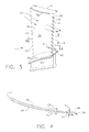
- the fan blades illustrated in Figure 3 have a serrated trailing edge which is generally serpentine along the radial span of the airfoil for promoting wake mixing as it is shed downstream from the individual blades for reducing the unsteady loading on the downstream stator vanes to correspondingly reduce fan noise.
- the serrated trailing edge 34 includes a row of serrations or notches 44 which define individual teeth or chevrons 46 therebetween.
- the notches thus create a serpentine trailing edge with the chevrons 46 extending aft in the downstream direction, with the notches interrupting the radial continuity of the pressure and suction sides of the airfoil locally along the trailing edge.
- the airfoil pressure and suction sides 28,30 may have any conventional configuration for pressurizing the fan air during operation.
- the pressure side 28 is generally concave whereas the suction side 30 is generally convex between the leading and trailing edges of the airfoil for creating different velocity distributions over both sides of the airfoil.
- the two separate boundary layers of air flowing along the pressure and suction sides may be joined in flow communication by the notches and forced mixed by the rotational movement of the chevrons during operation.
- the fan air is channeled axially aft between adjacent blades and in corresponding boundary layers along the opposite pressure and suction sides of each airfoil.
- the serrated trailing edge increases the effective surface area along which the two boundary layers meet and are mixed thereby.
- the trailing edge notches 44 preferably diverge in the aft direction, with the adjoining chevrons 46 correspondingly converging in the aft direction.
- the notches and chevrons are preferably triangular for promoting the generation of vortices as the air boundary layers are shed from the airfoil trailing edges, which vortices increase the mixing of the blade wakes prior to reaching the downstream stator vanes.
- the airfoil has a chord represented by its length C measured at each radial span between the leading and trailing edges of the airfoil.
- the airfoil has camber or curvature between its leading and trailing edges, with the pressure side being generally concave, and the suction side being generally convex.
- the thickness T of the airfoil may vary between the leading and trailing edges in a typical manner.
- the chevrons 46 illustrated in Figure 3 have an axial length A and a radial pitch spacing B.
- the length A and pitch B relative to the airfoil chord length C may be optimized for each design application for maximizing aerodynamic performance of the airfoil itself relative to the airfoil without the serrated trailing edge while effectively attenuating fan noise.
- the serrated trailing edge is a local change in configuration of the airfoil limited to the region of the airfoil directly adjacent the trailing edge within about 10% of the chord length therefrom.
- the number and size of the individual chevrons and notches may be selected from high to low density along the trailing edge for maximizing sound attenuation without significantly reducing aerodynamic performance.
- the chevrons 46 are axially coextensive with the airfoil in a common aerodynamic profile therewith, with the chevrons being tapered similarly with the remainder of the airfoil and decreasing in thickness in the aft direction terminating at the trailing edge.
- the airfoil may have substantially the same radial contour with or without the serrated trailing edge, with the serrated trailing edge being introduced by the notches extending along the camber lines of the airfoil.
- each chevron 46 remains coextensive with the remaining portion of the pressure side of the airfoil without discontinuity, and similarly, the suction side of each chevron 46 remains coextensive with the remaining portion of the airfoil suction side without discontinuity in the radial profile illustrated in Figure 4.
- the individual chevrons 46 adjoin each other at their respective bases which define the apexes of the intervening triangular notches 44. And, the radially adjoining chevrons extend in a substantially continuous row from the root 26 of the airfoil to the tip 38 thereof along the entire span of the trailing edge of the airfoil.
- Figure 5 illustrates an alternate embodiment of the chevrons 46 in the airfoil wherein instead of being coextensive with the camber line of the airfoil, illustrated in phantom line, the chevrons are disposed obliquely with the remainder of the airfoil.
- One or more of the chevrons 46 may be oblique with the pressure side 28 of the airfoil with an obtuse included angle therebetween.
- One or more of the chevrons 46 may be oblique with the suction side 30 of the airfoil with an included obtuse angle therebetween.
- the chevrons 46 may alternate obliquely from both sides of the airfoil at the trailing edge in yet another embodiment.
- each fan blade 14 typically includes twist from its root 36 to its tip 38, and has corresponding pressure loading varying from root to tip.
- the individual airfoils have a varying angle of attack with respect to the incoming fan air 24 and shed the fan air wakes at corresponding angles relative to the axial centerline axis of the engine. Accordingly, the specific size, configuration, and angular orientation of the chevrons may be varied for maximizing noise attenuation without compromising aerodynamic performance of the fan blades.
- each of the airfoils includes an inboard portion from the root 36 to near the mid-span of the airfoil and an outboard portion extending radially outwardly therefrom to the tip 38.
- the chevrons 46 need not extend along the full trailing edge of the airfoil, but in the exemplary embodiment illustrated in Figure 6 the chevrons are disposed along primarily only the airfoil inboard portion, with the outboard portion of the trailing edge being devoid of the chevrons adjacent the tip 38.
- the trailing edge from the mid-span to the tip is generally straight or arcuate in a conventional manner, without local interruption by the notches.
- This inboard embodiment of the serrated trailing edge has particular utility where the pressure loading of the specific fan blades is biased over the inboard span for which the increased mixing effectiveness of the serrated trailing edge is desired.
- the length of the aerodynamic streamlines between the fan blades and stator vanes is longer near the blade tips than near the blade roots.
- the inboard serrated trailing edge may then be used for increasing the mixing effectiveness along the shorter streamlines of the airfoil inboard portions than along the airfoil outboard portions which require little, if any, additional mixing effectiveness.
- Figure 7 illustrates an alternate embodiment of the fan blades in which the chevrons, designated 46B, are disposed along the outboard portion of the airfoil, with the inboard portion of the airfoil being devoid of the chevrons adjacent the airfoil root 36.
- This embodiment is particularly useful for fan blades in which pressure loading is biased in the outboard portion, and the chevrons are not otherwise required along the inboard portion from the mid-span to the root.
- the radial extent of the serrated trailing edge is limited for limiting pressure losses attributable thereto, while selectively introducing the serrated trailing edge for enhancing noise attenuation.
- the chevrons are preferably triangular in configuration, but may have any other suitable configuration which promotes sound attenuation without undesirable pressure losses.
- the chevrons designated 46B in Figure 7 and their defining notches are generally sinusoidal with arcuate apexes as opposed to the triangular chevrons and sharp notches illustrated in Figure 3.
- a particular advantage of the forced mixing of the fan wakes and the main fan air channeled between the blades as illustrated in Figure 2 is the ability to correspondingly decrease the spacing between the fan blades and the stator vanes 18. Since the chevrons promote mixing between the fan blades and vanes the axial spacing therebetween may be correspondingly reduced for a given level of acceptable fan noise. The reduced spacing between the blades and fans permits the entire engine to be correspondingly shorter which in turn reduces the overall weight thereof. In this way, the efficiency of the engine itself is correspondingly improved due to the improved mixing effectiveness of the serrated trailing edges of the fan blades.
Landscapes
- Engineering & Computer Science (AREA)
- Mechanical Engineering (AREA)
- General Engineering & Computer Science (AREA)
- Physics & Mathematics (AREA)
- Fluid Mechanics (AREA)
- Structures Of Non-Positive Displacement Pumps (AREA)
Abstract
Description
Claims (10)
- A serrated turbofan blade (14).
- A blade according to claim 1 comprising an airfoil (26) having leading and trailing edges (32,34), and said trailing edge is serrated.
- A blade according to claim 2 wherein said trailing edge (34) includes a row of notches (44) defining chevrons (46) therebetween.
- A blade according to claim 3 wherein said notches (44) diverge aft and said chevrons converge aft.
- A blade according to claim 3 wherein said chevrons (46) are triangular.
- A blade according to claim 3 wherein said chevrons (46) decrease in thickness aft.
- A blade according to claim 3 wherein said chevrons (46) adjoin each other in a row.
- A blade according to claim 3 wherein said chevrons (46) are coextensive with said airfoil (26) in a common aerodynamic profile therewith.
- A blade according to claim 3 wherein said chevrons (46) are disposed obliquely with said airfoil (26).
- A turbofan (10) comprising a row of serrated fan blades (14) disposed upstream from a row of stator vanes (18), each of said fan blades (14) being in accordance with any one of claims 1 to 9.
Applications Claiming Priority (2)
| Application Number | Priority Date | Filing Date | Title |
|---|---|---|---|
| US907980 | 1997-08-11 | ||
| US09/907,980 US6733240B2 (en) | 2001-07-18 | 2001-07-18 | Serrated fan blade |
Publications (3)
| Publication Number | Publication Date |
|---|---|
| EP1277966A2 true EP1277966A2 (en) | 2003-01-22 |
| EP1277966A3 EP1277966A3 (en) | 2003-10-29 |
| EP1277966B1 EP1277966B1 (en) | 2006-06-07 |
Family
ID=25424957
Family Applications (1)
| Application Number | Title | Priority Date | Filing Date |
|---|---|---|---|
| EP02254867A Expired - Lifetime EP1277966B1 (en) | 2001-07-18 | 2002-07-11 | Serrated fan blade |
Country Status (4)
| Country | Link |
|---|---|
| US (1) | US6733240B2 (en) |
| EP (1) | EP1277966B1 (en) |
| JP (1) | JP4130337B2 (en) |
| DE (1) | DE60212007T2 (en) |
Cited By (11)
| Publication number | Priority date | Publication date | Assignee | Title |
|---|---|---|---|---|
| WO2005056984A1 (en) | 2003-12-06 | 2005-06-23 | Eads Deutschland Gmbh | Method for reducing the noise of turbo generators by modifying the surface circulation of a stator |
| EP1582695A1 (en) * | 2004-03-26 | 2005-10-05 | Siemens Aktiengesellschaft | Turbomachine blade |
| EP2301841A2 (en) | 2009-09-24 | 2011-03-30 | Rolls-Royce plc | Variable shape rotor blade |
| GB2475140A (en) * | 2009-11-06 | 2011-05-11 | Dresser Rand Co | An Exhaust Ring and Method to Reduce Turbine Acoustic Signature |
| CN102996509A (en) * | 2012-09-27 | 2013-03-27 | 宁波狮球通风机电有限公司 | Centrifugal blower |
| EP2014870A3 (en) * | 2007-07-09 | 2013-10-09 | General Electric Company | Airfoil for use in rotary machines and method for fabricating same |
| EP2708755A1 (en) * | 2012-09-12 | 2014-03-19 | LG Electronics, Inc. | Fan |
| EP2653699A3 (en) * | 2012-04-17 | 2017-05-17 | General Electric Company | Modular louver system |
| WO2019158877A1 (en) * | 2018-02-16 | 2019-08-22 | Safran Aircraft Engines | Turbomachine with serrated-profile flow-splitter nose |
| WO2020079335A1 (en) * | 2018-10-18 | 2020-04-23 | Safran Aircraft Engines | Profiled structure for an aircraft or turbomachine |
| RU2780265C2 (en) * | 2018-02-16 | 2022-09-21 | Сафран Эйркрафт Энджинз | Turbomachine with slat for flow separation, having gear profile |
Families Citing this family (81)
| Publication number | Priority date | Publication date | Assignee | Title |
|---|---|---|---|---|
| USD289525S (en) * | 1984-10-01 | 1987-04-28 | Industrial Tools, Inc. | Slicing machine for magnetic tape or the like |
| FR2825142B1 (en) * | 2001-05-22 | 2003-08-29 | Conseils Etudes Et Recherches En Gestion De Lair Cerga | FAN INTENDED TO BE ASSOCIATED WITH AN AIR EXHAUST DUCT OUTSIDE AT LEAST ONE PREMISES |
| EP1338793A3 (en) * | 2002-02-22 | 2010-09-01 | Mitsubishi Heavy Industries, Ltd. | Serrated wind turbine blade trailing edge |
| GB0314123D0 (en) * | 2003-06-18 | 2003-07-23 | Rolls Royce Plc | A gas turbine engine |
| US6905303B2 (en) * | 2003-06-30 | 2005-06-14 | General Electric Company | Methods and apparatus for assembling gas turbine engines |
| US7305817B2 (en) | 2004-02-09 | 2007-12-11 | General Electric Company | Sinuous chevron exhaust nozzle |
| JP4665472B2 (en) * | 2004-09-28 | 2011-04-06 | パナソニック株式会社 | Blower |
| KR100719103B1 (en) | 2005-09-26 | 2007-05-17 | 주식회사 에어로네트 | Hybrid Design Method for Turbo-type Rear Wing Multiple Impellers |
| JP2007149211A (en) * | 2005-11-28 | 2007-06-14 | Hitachi Global Storage Technologies Netherlands Bv | Magnetic disk unit |
| EP1801422B1 (en) * | 2005-12-22 | 2013-06-12 | Ziehl-Abegg AG | Fan and fan blade |
| WO2008108881A2 (en) * | 2006-09-08 | 2008-09-12 | Steven Sullivan | Method and apparatus for mitigating trailing vortex wakes of lifting or thrust generating bodies |
| US20090074585A1 (en) * | 2007-09-19 | 2009-03-19 | General Electric Company | Wind turbine blades with trailing edge serrations |
| KR101436628B1 (en) * | 2007-10-23 | 2014-09-02 | 엘지전자 주식회사 | Cross flow fan amd air conditioner |
| US8540490B2 (en) * | 2008-06-20 | 2013-09-24 | General Electric Company | Noise reduction in a turbomachine, and a related method thereof |
| US8197203B2 (en) * | 2008-09-22 | 2012-06-12 | Automotive Components Holdings, Llc | Air diffuser for a HVAC system |
| US9739296B2 (en) * | 2008-09-25 | 2017-08-22 | Parafluidics Llc | Channeling fluidic waveguide surfaces and tubes |
| US20110006165A1 (en) * | 2009-07-10 | 2011-01-13 | Peter Ireland | Application of conformal sub boundary layer vortex generators to a foil or aero/ hydrodynamic surface |
| DE102009032719A1 (en) * | 2009-07-14 | 2011-01-20 | Rolls-Royce Deutschland Ltd & Co Kg | propeller |
| DE102009033756A1 (en) * | 2009-07-17 | 2011-01-20 | Rolls-Royce Deutschland Ltd & Co Kg | Axial compressor, in particular for an aircraft gas turbine |
| US8608429B2 (en) | 2010-05-28 | 2013-12-17 | General Electric Company | System and method for enhanced turbine wake mixing via fluidic-generated vortices |
| US7976276B2 (en) * | 2010-11-04 | 2011-07-12 | General Electric Company | Noise reducer for rotor blade in wind turbine |
| US8523515B2 (en) | 2010-11-15 | 2013-09-03 | General Electric Company | Noise reducer for rotor blade in wind turbine |
| US8267657B2 (en) * | 2010-12-16 | 2012-09-18 | General Electric Company | Noise reducer for rotor blade in wind turbine |
| US8556584B2 (en) * | 2011-02-03 | 2013-10-15 | General Electric Company | Rotating component of a turbine engine |
| RU2550370C2 (en) | 2011-05-11 | 2015-05-10 | Альстом Текнолоджи Лтд | Centrifugal nozzle with projecting parts |
| EP2712399B1 (en) * | 2011-05-16 | 2016-12-07 | LM WP Patent Holding A/S | Wind turbine blade with noise reduction devices and related method |
| US8414261B2 (en) | 2011-05-31 | 2013-04-09 | General Electric Company | Noise reducer for rotor blade in wind turbine |
| WO2013070296A2 (en) * | 2011-08-19 | 2013-05-16 | Aerovironment, Inc. | Aircraft system for reduced observer visibility |
| US8834127B2 (en) | 2011-09-09 | 2014-09-16 | General Electric Company | Extension for rotor blade in wind turbine |
| US8984890B2 (en) * | 2011-10-31 | 2015-03-24 | General Electric Company | Turbofan engine mixer assembly |
| US9909425B2 (en) * | 2011-10-31 | 2018-03-06 | Pratt & Whitney Canada Corporation | Blade for a gas turbine engine |
| US8998575B2 (en) * | 2011-11-14 | 2015-04-07 | United Technologies Corporation | Structural stator airfoil |
| US9341158B2 (en) * | 2011-12-08 | 2016-05-17 | Inventus Holdings, Llc | Quiet wind turbine blade |
| GB2497739A (en) * | 2011-12-19 | 2013-06-26 | Rolls Royce Plc | Rotor blade with serrated trailing edge |
| US8430638B2 (en) | 2011-12-19 | 2013-04-30 | General Electric Company | Noise reducer for rotor blade in wind turbine |
| US9121294B2 (en) * | 2011-12-20 | 2015-09-01 | General Electric Company | Fan blade with composite core and wavy wall trailing edge cladding |
| US9249666B2 (en) | 2011-12-22 | 2016-02-02 | General Electric Company | Airfoils for wake desensitization and method for fabricating same |
| US9340277B2 (en) | 2012-02-29 | 2016-05-17 | General Electric Company | Airfoils for use in rotary machines |
| US20130280085A1 (en) * | 2012-04-23 | 2013-10-24 | General Electric Company | Flow modification device for rotor blade in wind turbine |
| ES2746966T3 (en) * | 2012-06-01 | 2020-03-09 | MTU Aero Engines AG | Transition channel for a turbomachine and turbomachine |
| US9581034B2 (en) * | 2013-03-14 | 2017-02-28 | Elliott Company | Turbomachinery stationary vane arrangement for disk and blade excitation reduction and phase cancellation |
| DE102013206207A1 (en) * | 2013-04-09 | 2014-10-09 | MTU Aero Engines AG | Airfoil for a turbomachine with trailing edge profiling, blade and integrally bladed rotor |
| US9494134B2 (en) | 2013-11-20 | 2016-11-15 | General Electric Company | Noise reducing extension plate for rotor blade in wind turbine |
| GB201410675D0 (en) | 2014-06-16 | 2014-07-30 | Univ Brunel | Noise reduction to the trailing edge of fluid dynamic bodies |
| US9849976B2 (en) | 2014-08-19 | 2017-12-26 | The Boeing Company | Noise reducing profile for helicopter rotor blade tracking wedges |
| US11041388B2 (en) | 2015-03-30 | 2021-06-22 | Pratt & Whitney Canada Corp. | Blade cutback distribution in rotor for noise reduction |
| US10180125B2 (en) | 2015-04-20 | 2019-01-15 | General Electric Company | Airflow configuration for a wind turbine rotor blade |
| GB201512688D0 (en) * | 2015-07-20 | 2015-08-26 | Rolls Royce Plc | Aerofoil |
| EP3181895A1 (en) * | 2015-12-17 | 2017-06-21 | LM WP Patent Holding A/S | Splitter plate arrangement for a serrated wind turbine blade |
| GB201602895D0 (en) * | 2016-02-19 | 2016-04-06 | Rolls Royce Plc | Aerofoil |
| US10436037B2 (en) | 2016-07-22 | 2019-10-08 | General Electric Company | Blade with parallel corrugated surfaces on inner and outer surfaces |
| US10465525B2 (en) | 2016-07-22 | 2019-11-05 | General Electric Company | Blade with internal rib having corrugated surface(s) |
| US10443399B2 (en) | 2016-07-22 | 2019-10-15 | General Electric Company | Turbine vane with coupon having corrugated surface(s) |
| US10465520B2 (en) | 2016-07-22 | 2019-11-05 | General Electric Company | Blade with corrugated outer surface(s) |
| US10450868B2 (en) | 2016-07-22 | 2019-10-22 | General Electric Company | Turbine rotor blade with coupon having corrugated surface(s) |
| US10465652B2 (en) | 2017-01-26 | 2019-11-05 | General Electric Company | Vortex generators for wind turbine rotor blades having noise-reducing features |
| CN106939900A (en) * | 2017-04-10 | 2017-07-11 | 温州职业技术学院 | A kind of turbulent low noise draught fan impeller |
| GB201708297D0 (en) * | 2017-05-24 | 2017-07-05 | Rolls Royce Plc | Preventing electrical breakdown |
| GB201708289D0 (en) * | 2017-05-24 | 2017-07-05 | Rolls Royce Plc | Preventing electrical breakdown |
| USD901669S1 (en) | 2017-09-29 | 2020-11-10 | Carrier Corporation | Contoured fan blade |
| JP7713776B2 (en) * | 2017-09-29 | 2025-07-28 | キャリア コーポレイション | Axial flow fan blade with wavy airfoils and trailing edge serrations |
| GB201718069D0 (en) * | 2017-11-01 | 2017-12-13 | Rolls Royce Plc | Aerofoil |
| CN207795681U (en) * | 2018-01-13 | 2018-08-31 | 广东美的环境电器制造有限公司 | Axial flow fan blade, axial flow fan blade assembly, axial flow fan duct assembly |
| US10767623B2 (en) | 2018-04-13 | 2020-09-08 | General Electric Company | Serrated noise reducer for a wind turbine rotor blade |
| PT3587798T (en) * | 2018-06-27 | 2020-11-23 | Siemens Gamesa Renewable Energy As | Aerodynamic structure |
| ES3037885T3 (en) * | 2018-06-27 | 2025-10-07 | Siemens Gamesa Renewable Energy As | Aerodynamic structure |
| BE1026579B1 (en) * | 2018-08-31 | 2020-03-30 | Safran Aero Boosters Sa | PROTUBERANCE VANE FOR TURBOMACHINE COMPRESSOR |
| US10746157B2 (en) | 2018-08-31 | 2020-08-18 | General Electric Company | Noise reducer for a wind turbine rotor blade having a cambered serration |
| US20210115796A1 (en) * | 2019-10-18 | 2021-04-22 | United Technologies Corporation | Airfoil component with trailing end margin and cutback |
| FR3103231B1 (en) * | 2019-11-19 | 2022-07-29 | Safran Aircraft Engines | Wave blade turbomachine |
| US12162591B1 (en) | 2019-12-20 | 2024-12-10 | United States Of America As Represented By The Administrator Of Nasa | Anti-phase noise suppression rotor technologies |
| GB2592009B (en) * | 2020-02-11 | 2022-08-24 | Gkn Aerospace Sweden Ab | Compressor blade |
| CN115559934A (en) * | 2020-03-10 | 2023-01-03 | 依必安派特穆尔芬根有限两合公司 | Fan and fan blade |
| WO2021199802A1 (en) * | 2020-04-01 | 2021-10-07 | 株式会社Ihi | Static blade and aircraft gas turbine engine |
| CN113833568B (en) * | 2020-06-24 | 2022-09-06 | 中国航发商用航空发动机有限责任公司 | Splitter ring, aircraft engine and splitter ring manufacturing method |
| US11428160B2 (en) * | 2020-12-31 | 2022-08-30 | General Electric Company | Gas turbine engine with interdigitated turbine and gear assembly |
| US11702939B2 (en) * | 2021-07-23 | 2023-07-18 | Pratt & Whitney Canada Corp. | Fan icing detection system |
| BE1030724B1 (en) * | 2022-07-22 | 2024-02-19 | Safran Aero Boosters | TURBOMACHINE ASSEMBLY |
| US12378887B2 (en) * | 2022-11-28 | 2025-08-05 | General Electric Company | Airfoil assembly |
| US12215596B2 (en) | 2023-06-30 | 2025-02-04 | General Electric Company | Unducted airfoil assembly |
| FR3151628A1 (en) * | 2023-07-26 | 2025-01-31 | Safran Aircraft Engines | Blower for aeronautical propulsion |
Family Cites Families (18)
| Publication number | Priority date | Publication date | Assignee | Title |
|---|---|---|---|---|
| US1862827A (en) * | 1930-01-22 | 1932-06-14 | Parsons | Steam turbine |
| GB789883A (en) | 1954-08-20 | 1958-01-29 | Power Jets Res & Dev Ltd | High speed aerofoil |
| US3215172A (en) | 1962-12-24 | 1965-11-02 | Nilsson Robbins & Anderson | Jet engine noise suppressor with shroud for aspiration of air into exhaust stream |
| US3365126A (en) * | 1965-09-01 | 1968-01-23 | Gen Electric | Compressor blade |
| FR1536561A (en) * | 1967-08-22 | 1968-08-16 | Gen Electric | Axial flow compressor fins |
| US3403893A (en) * | 1967-12-05 | 1968-10-01 | Gen Electric | Axial flow compressor blades |
| US3568792A (en) | 1969-06-18 | 1971-03-09 | Rohr Corp | Sound-suppressing and thrust-reversing apparatus |
| US3853428A (en) * | 1972-01-27 | 1974-12-10 | Bolt Beranek & Newman | Foil structures with reduced sound generation |
| IT1036993B (en) * | 1974-07-02 | 1979-10-30 | Rotron Inc | DEVICE FOR THE MOVEMENT OF A FLUID |
| US4318669A (en) * | 1980-01-07 | 1982-03-09 | The United States Of America As Represented By The Secretary Of The Air Force | Vane configuration for fluid wake re-energization |
| US4830315A (en) | 1986-04-30 | 1989-05-16 | United Technologies Corporation | Airfoil-shaped body |
| JPS63113101A (en) * | 1986-10-31 | 1988-05-18 | Hitachi Ltd | blade cascade device |
| GB8829792D0 (en) * | 1988-12-21 | 1989-07-05 | Marconi Co Ltd | Noise reduction method |
| US5169288A (en) | 1991-09-06 | 1992-12-08 | General Electric Company | Low noise fan assembly |
| DE4208751A1 (en) * | 1992-02-27 | 1993-11-11 | Fritz Karl Hausser | Reducing resistance to aerofoil or hydrofoil passing through medium e.g. air or water - uses array of teeth formed on leading and/or trailing edge of aerofoil or hydrofoil section |
| NL9301910A (en) * | 1993-11-04 | 1995-06-01 | Stork Prod Eng | Wind turbine. |
| GB2289921A (en) | 1994-06-03 | 1995-12-06 | A E Harris Limited | Nozzle for turbofan aeroengines |
| JP3448136B2 (en) | 1994-11-08 | 2003-09-16 | 三菱重工業株式会社 | Propeller fan |
-
2001
- 2001-07-18 US US09/907,980 patent/US6733240B2/en not_active Expired - Fee Related
-
2002
- 2002-07-11 EP EP02254867A patent/EP1277966B1/en not_active Expired - Lifetime
- 2002-07-11 DE DE60212007T patent/DE60212007T2/en not_active Expired - Lifetime
- 2002-07-18 JP JP2002208988A patent/JP4130337B2/en not_active Expired - Fee Related
Cited By (20)
| Publication number | Priority date | Publication date | Assignee | Title |
|---|---|---|---|---|
| US7758296B2 (en) | 2003-12-06 | 2010-07-20 | Eads Deutschland Gmbh | Method for reducing the noise of turbo engines |
| WO2005056984A1 (en) | 2003-12-06 | 2005-06-23 | Eads Deutschland Gmbh | Method for reducing the noise of turbo generators by modifying the surface circulation of a stator |
| EP1582695A1 (en) * | 2004-03-26 | 2005-10-05 | Siemens Aktiengesellschaft | Turbomachine blade |
| EP2014870A3 (en) * | 2007-07-09 | 2013-10-09 | General Electric Company | Airfoil for use in rotary machines and method for fabricating same |
| EP2301841A2 (en) | 2009-09-24 | 2011-03-30 | Rolls-Royce plc | Variable shape rotor blade |
| US8657561B2 (en) | 2009-09-24 | 2014-02-25 | Rolls-Royce Plc | Variable shape rotor blade |
| GB2475140A (en) * | 2009-11-06 | 2011-05-11 | Dresser Rand Co | An Exhaust Ring and Method to Reduce Turbine Acoustic Signature |
| EP2653699A3 (en) * | 2012-04-17 | 2017-05-17 | General Electric Company | Modular louver system |
| EP2708755A1 (en) * | 2012-09-12 | 2014-03-19 | LG Electronics, Inc. | Fan |
| US9518585B2 (en) | 2012-09-12 | 2016-12-13 | Lg Electronics Inc. | Fan |
| CN102996509A (en) * | 2012-09-27 | 2013-03-27 | 宁波狮球通风机电有限公司 | Centrifugal blower |
| WO2019158877A1 (en) * | 2018-02-16 | 2019-08-22 | Safran Aircraft Engines | Turbomachine with serrated-profile flow-splitter nose |
| FR3078101A1 (en) * | 2018-02-16 | 2019-08-23 | Safran Aircraft Engines | TURBOMACHINE HAVING A SERRATION PROFILE FLOW SEPARATION SEPARATION |
| CN111742116A (en) * | 2018-02-16 | 2020-10-02 | 赛峰航空器发动机 | Turbine engine with split slats with sawtooth profile |
| RU2780265C2 (en) * | 2018-02-16 | 2022-09-21 | Сафран Эйркрафт Энджинз | Turbomachine with slat for flow separation, having gear profile |
| US11525365B2 (en) | 2018-02-16 | 2022-12-13 | Safran Aircraft Engines | Turbomachine with serrated-profile flow-splitter nose |
| WO2020079335A1 (en) * | 2018-10-18 | 2020-04-23 | Safran Aircraft Engines | Profiled structure for an aircraft or turbomachine |
| FR3087482A1 (en) * | 2018-10-18 | 2020-04-24 | Safran Aircraft Engines | PROFILED STRUCTURE FOR AIRCRAFT OR TURBOMACHINE |
| RU2789369C2 (en) * | 2018-10-18 | 2023-02-02 | Сафран Эркрафт Энджинз | Profiled structure for aircraft or gas-turbine engine |
| US11668196B2 (en) | 2018-10-18 | 2023-06-06 | Safran Aircraft Engines | Profiled structure for an aircraft or turbomachine |
Also Published As
| Publication number | Publication date |
|---|---|
| US6733240B2 (en) | 2004-05-11 |
| DE60212007T2 (en) | 2006-12-21 |
| JP2003090300A (en) | 2003-03-28 |
| EP1277966A3 (en) | 2003-10-29 |
| JP4130337B2 (en) | 2008-08-06 |
| EP1277966B1 (en) | 2006-06-07 |
| DE60212007D1 (en) | 2006-07-20 |
| US20030152459A1 (en) | 2003-08-14 |
Similar Documents
| Publication | Publication Date | Title |
|---|---|---|
| EP1277966B1 (en) | Serrated fan blade | |
| US11300136B2 (en) | Aircraft fan with low part-span solidity | |
| US11732588B2 (en) | Profiled structure for an aircraft or turbomachine for an aircraft | |
| US7476086B2 (en) | Tip cambered swept blade | |
| CA2333843C (en) | Fluted compressor flowpath | |
| EP1712738B1 (en) | Low solidity turbofan | |
| US6508630B2 (en) | Twisted stator vane | |
| JP5551856B2 (en) | Airfoil for use in a rotating machine and method of making the same | |
| US20070025847A1 (en) | Gas turbine | |
| CA2548133C (en) | Counterrotating turbofan engine | |
| EP1111191B1 (en) | Stator with particular circumferential spacing of the airfoils | |
| EP1731716B1 (en) | Forward tilted turbine nozzle | |
| US8764380B2 (en) | Rotor blade | |
| US20200355085A1 (en) | Turbomachine fan flow-straightener vane, turbomachine assembly comprising such a vane, and turbomachine equipped with said vane or with said assembly | |
| EP2689107A1 (en) | High camber stator vane | |
| US20240309769A1 (en) | Outlet guide vane assembly for a turbofan engine | |
| US20200123903A1 (en) | Fluidfoil | |
| US20250223909A1 (en) | Outlet guide vane assembly for a turbofan engine |
Legal Events
| Date | Code | Title | Description |
|---|---|---|---|
| PUAI | Public reference made under article 153(3) epc to a published international application that has entered the european phase |
Free format text: ORIGINAL CODE: 0009012 |
|
| AK | Designated contracting states |
Kind code of ref document: A2 Designated state(s): AT BE BG CH CY CZ DE DK EE ES FI FR GB GR IE IT LI LU MC NL PT SE SK TR |
|
| AX | Request for extension of the european patent |
Free format text: AL;LT;LV;MK;RO;SI |
|
| PUAL | Search report despatched |
Free format text: ORIGINAL CODE: 0009013 |
|
| AK | Designated contracting states |
Kind code of ref document: A3 Designated state(s): AT BE BG CH CY CZ DE DK EE ES FI FR GB GR IE IT LI LU MC NL PT SE SK TR |
|
| AX | Request for extension of the european patent |
Extension state: AL LT LV MK RO SI |
|
| RIC1 | Information provided on ipc code assigned before grant |
Ipc: 7F 04D 29/32 A Ipc: 7F 04D 29/68 B Ipc: 7F 01D 5/14 B |
|
| 17P | Request for examination filed |
Effective date: 20040429 |
|
| AKX | Designation fees paid |
Designated state(s): DE FR GB IT |
|
| 17Q | First examination report despatched |
Effective date: 20050427 |
|
| GRAP | Despatch of communication of intention to grant a patent |
Free format text: ORIGINAL CODE: EPIDOSNIGR1 |
|
| GRAS | Grant fee paid |
Free format text: ORIGINAL CODE: EPIDOSNIGR3 |
|
| GRAA | (expected) grant |
Free format text: ORIGINAL CODE: 0009210 |
|
| AK | Designated contracting states |
Kind code of ref document: B1 Designated state(s): DE FR GB IT |
|
| REG | Reference to a national code |
Ref country code: GB Ref legal event code: FG4D |
|
| REF | Corresponds to: |
Ref document number: 60212007 Country of ref document: DE Date of ref document: 20060720 Kind code of ref document: P |
|
| ET | Fr: translation filed | ||
| PLBE | No opposition filed within time limit |
Free format text: ORIGINAL CODE: 0009261 |
|
| STAA | Information on the status of an ep patent application or granted ep patent |
Free format text: STATUS: NO OPPOSITION FILED WITHIN TIME LIMIT |
|
| 26N | No opposition filed |
Effective date: 20070308 |
|
| PGFP | Annual fee paid to national office [announced via postgrant information from national office to epo] |
Ref country code: DE Payment date: 20100728 Year of fee payment: 9 Ref country code: FR Payment date: 20100805 Year of fee payment: 9 Ref country code: IT Payment date: 20100723 Year of fee payment: 9 |
|
| PGFP | Annual fee paid to national office [announced via postgrant information from national office to epo] |
Ref country code: GB Payment date: 20100726 Year of fee payment: 9 |
|
| GBPC | Gb: european patent ceased through non-payment of renewal fee |
Effective date: 20110711 |
|
| REG | Reference to a national code |
Ref country code: FR Ref legal event code: ST Effective date: 20120330 |
|
| PG25 | Lapsed in a contracting state [announced via postgrant information from national office to epo] |
Ref country code: DE Free format text: LAPSE BECAUSE OF NON-PAYMENT OF DUE FEES Effective date: 20120201 Ref country code: FR Free format text: LAPSE BECAUSE OF NON-PAYMENT OF DUE FEES Effective date: 20110801 |
|
| REG | Reference to a national code |
Ref country code: DE Ref legal event code: R119 Ref document number: 60212007 Country of ref document: DE Effective date: 20120201 |
|
| PG25 | Lapsed in a contracting state [announced via postgrant information from national office to epo] |
Ref country code: IT Free format text: LAPSE BECAUSE OF NON-PAYMENT OF DUE FEES Effective date: 20110711 |
|
| PG25 | Lapsed in a contracting state [announced via postgrant information from national office to epo] |
Ref country code: GB Free format text: LAPSE BECAUSE OF NON-PAYMENT OF DUE FEES Effective date: 20110711 |