EP1277862A1 - Loom for weaving leno fabrics - Google Patents
Loom for weaving leno fabrics Download PDFInfo
- Publication number
- EP1277862A1 EP1277862A1 EP02405507A EP02405507A EP1277862A1 EP 1277862 A1 EP1277862 A1 EP 1277862A1 EP 02405507 A EP02405507 A EP 02405507A EP 02405507 A EP02405507 A EP 02405507A EP 1277862 A1 EP1277862 A1 EP 1277862A1
- Authority
- EP
- European Patent Office
- Prior art keywords
- stop
- needles
- needle bar
- leno
- standing
- Prior art date
- Legal status (The legal status is an assumption and is not a legal conclusion. Google has not performed a legal analysis and makes no representation as to the accuracy of the status listed.)
- Withdrawn
Links
- 238000009941 weaving Methods 0.000 title claims abstract description 18
- 239000004744 fabric Substances 0.000 title claims abstract description 13
- 230000001154 acute effect Effects 0.000 claims abstract description 6
- 241000446313 Lamella Species 0.000 claims abstract description 5
- 230000008859 change Effects 0.000 claims description 7
- 238000004519 manufacturing process Methods 0.000 claims description 4
- 238000005266 casting Methods 0.000 claims 1
- 238000003780 insertion Methods 0.000 description 3
- 230000037431 insertion Effects 0.000 description 3
- 238000000034 method Methods 0.000 description 2
- 230000008569 process Effects 0.000 description 2
- 235000014676 Phragmites communis Nutrition 0.000 description 1
- 238000004873 anchoring Methods 0.000 description 1
- 230000008901 benefit Effects 0.000 description 1
- 230000015572 biosynthetic process Effects 0.000 description 1
- 230000001419 dependent effect Effects 0.000 description 1
- 238000007654 immersion Methods 0.000 description 1
- 230000007246 mechanism Effects 0.000 description 1
Images

Classifications
-
- D—TEXTILES; PAPER
- D03—WEAVING
- D03C—SHEDDING MECHANISMS; PATTERN CARDS OR CHAINS; PUNCHING OF CARDS; DESIGNING PATTERNS
- D03C7/00—Leno or similar shedding mechanisms
- D03C7/06—Mechanisms having eyed needles for moving warp threads from side to side of other warp threads
-
- D—TEXTILES; PAPER
- D03—WEAVING
- D03C—SHEDDING MECHANISMS; PATTERN CARDS OR CHAINS; PUNCHING OF CARDS; DESIGNING PATTERNS
- D03C7/00—Leno or similar shedding mechanisms
Definitions
- the invention relates to a weaving machine for producing leno fabrics and a needle bar for such a weaving machine.
- the element for the leno threads can be, for example Laying rail or leno heald frame (see DE-A-23 53 658) his.
- the element for the upright threads can, for example, be a needle bar or be an upright thread element that also functions as a Webblatts (see. DE-A-466 340).
- a leno tableware which a number of Includes standing needles; between two adjacent standing needles a stop slat for a safe change of the leno threads arranged.
- the standing needles and stop slats are on their lower one End clamped in a beam; at the top are the Standing needles free, the stop slats loosely guided.
- the object of the invention is to produce a weaving machine To create leno fabrics with a handicap between the standing round Leno threads are defused. This object is achieved by the in claim 1 defined weaving machine solved. In addition, funds should be created to eliminate the mentioned consequence of thread obstruction. This additional task is solved by the weaving machine according to claim 5.
- the weaving machine for producing leno fabrics has one element Standing needles, in particular a needle bar. Form the standing needles a row in the direction of the longitudinal extension of the element. The Side surfaces of the standing needles close with a normal to the above Longitudinal extension an acute angle that is greater than 1 °.
- claims 2 to 6 relate to advantageous embodiments the weaving machine according to the invention.
- Subject matter of claims 7 to 10 is a needle bar to a weaving machine according to one of claims 1 until 6.
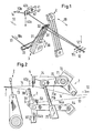
- a leno fabric 1 is made Weft threads 12 and warp threads, namely upright threads 13 and leno threads 14.
- the upright threads 13 with a needle bar 3 and the leno threads 14 are guided with an insert element 4.
- the needle bar 3 carries needles 31 with eyelets 32, which are relatively stiff eyelet rods.
- the Insert element 4 contains an insert rail 41 which has a perforated rail Holes 42 is.
- a sequence of regularly arranged holes 42 is dash-dotted lines indicated as strips 42 '.
- the Transport direction 10 of the warp threads 13 and 14 (arrows 10a and 10b) and the Fabric 1 (arrow 10c) from the back to the front.
- the transport direction 10 runs from right to left.
- a reed is used to strike a freshly inserted weft thread 12 ' 2 operated between the needle bar 3 and the tissue 1: double arrow 20.
- Die Needle bar 3 and the insert element 4 are up and down in opposite directions moved: double arrows 30 or 40a.
- the first movement component 40a the insertion rail 41 is a second movement component Offset movement 40b overlaid.
- the stroke of the offset movement 40b is so chosen that the leno thread 14 each from a first gap, the between adjacent standing needles 31 and 31 'to a second Gap that is adjacent to the first is moved. After a shot entry this change of position of the leno thread 14 is again in reverse Direction.
- the stroke is at least equal to the distance between the adjacent needles 31 and 31 '.
- stop lamellae 34 are arranged between the standing needles (see FIG. 3), which protrude above the standing needles 31 and so the immersion of the Force leno thread 14 into the correct gap 34. So the first Movement component 40a of the insert element 4 outside the area of the upright threads 13 can be done via a deflecting rod 53 deflected downwards.
- Insert element 4 and the needle bar 3 move so that the for Upright and leno threads 13 and 14 necessary movement sequence for Formation of a shed for the weft insertion results.
- the needle bar 3 is on a first toggle lever 54a, 54b between a first axis of the Swivel arrangement (not shown) and a fixed joint 54 arranged. By an up and down movement 30 'of the lever arm 54b results the movement 30 of the needle bar 3.
- a second axis 71 that is parallel is arranged to the first axis, a second toggle lever 71a, 71b and an up and down movement 70 'which is reciprocal to the movement 30' in an opposite pendulum rotation 70 with respect to the first axis is offset.
- a Connection 74 between the second axis 71 and the insert element 4 transfers the swivel movement to it and thus generates the vertical one Movement component 40a of the insertion rail 41.
- the horizontal Movement component 40b is not shown with another Mechanism manufactured.
- the needle bar 3 shown in detail in FIG. 3 comprises a large number of standing needles 31 which a row in the direction of the longitudinal extension A of Form bar 31.
- the inclination of the needles 31 is in relation to the upright threads 13 manufactured in such a way that the double deflection of the upright threads 13 reduced when passing through the eyelets 32.
- the standing needles 31 and stop lamella 34 are in one known manner attached to the base in a base 5.
- the Stop slats 34 are elastic and resiliently thin, so that a lateral deflection in the direction of the Can exercise barrel extension A.
- the inclined standing needles 31 and stop plates 34 are included Advantage aligned parallel to each other.
- the Cross sections each have the shape of a segment of a circle.
- the lower part the base 5 is a profile rod 50 with a longitudinal groove into which the or individual standing needles 31 are inserted for anchoring.
- the upper ends of the stop slats 34 are through a wire 35 or another linear element, for example a fine chain, connected. This is a measure to take one over the stop slat prevent the leno threads from soaring upwards.
- the wire or the element is each in an opening 35 of the Stop slat 34 inserted loosely, so that the stop slats 34 laterally remain deflectable.
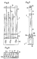
- FIG. 4 shows a cross section through the standing needles 31, 31 'and Stop slats 34 of a known needle bar 3, the section through the eyelets 32 is placed.
- the needles 31 are perpendicular to Barrel extension A.
- the alley width, d. H. the distance a between Standing needle 31 and stop lamella 34 is drawn so that a Change of position of the leno thread 14 - indicated by the arrow 40c - seems to be able to be carried out unimpeded by the upright thread 13.
- the space is narrower and / or it is done Transverse vibrations of the threads, so that there is usually a mutual disability between the threads 13 and 14 results.
- the solution according to the invention is shown by which the disability can be defused or eliminated: the standing needles 31 and - in Example shown - the stop slats 34 are at an acute angle ⁇ inclined relative to the barrel extension A (see Fig. 4).
- the leno thread 14 is inclined by the outer edge 310 (or 310 'for the dot-dash position of the leno thread 14) of the Upright thread 13 pushed away.
- the tendency has the consequence that the alley width is smaller than that original distance is a. Thanks to the resilience of the stop plate 34 this can be deflected laterally by the leno thread 14 (arrows 340), so that the alley width becomes sufficiently large.
- Figures 6 to 7 show two side views and a top view of one second embodiment of the needle bar 3.
- the two Base rods 51 a and 51 b are designed such that the standing needles 31 and stop lamellae 34 can be inserted into grooves 510. The distances are no longer determined by a wire 52 (Fig. 3), but by the location of the grooves 510.
- the arrangement of the standing needles 31 and stop lamellae 34 are terminated at each end by a stop rod 37. These are each arranged adjacent to a standing needle 31 and form a largely rigid stop for the terminal leno threads 34 terminal streets are therefore somewhat wider than the inner streets Lanes trained.
Abstract
Description
Die Erfindung betrifft eine Webmaschine zum Herstellen von Drehergeweben sowie eine Nadelbarre zu einer solchen Webmaschine.The invention relates to a weaving machine for producing leno fabrics and a needle bar for such a weaving machine.
Bei einem Verfahren zur Herstellung von Drehergeweben werden einerseits Steherfäden mit einer Nadelbarre geführt; andererseits werden Dreherfäden mit einem Webschaft geführt, der relativ zur Nadelbarre auf und ab sowie hin und her bewegt wird. Die vertikale Führungsbewegung der Dreherfäden ist eine erste Bewegungskomponente, der mit Hilfe eines geeignet ausgebildeten Schaftrahmens eine zweite Bewegungskomponente überlagert wird. Mit einem Einlegeelement des Schaftrahmens werden die Dreherfäden seitlich verschoben, d. h. es wird eine Versatzbewegung ausgeführt, so dass durch Lagenwechsel der Dreherfäden die für Drehergewebe typische Bindung entsteht.In a process for producing leno fabrics, on the one hand Upright threads guided with a needle bar; on the other hand are leno threads guided with a heald frame that goes up and down and down relative to the needle bar and moved here. The vertical guide movement of the leno threads is a first movement component, which with the help of a suitably trained A second movement component is superimposed on the shaft frame. With The insert threads on the side of the shaft frame become the leno threads postponed, d. H. an offset movement is carried out so that by Change of position of the leno threads is the weave typical of leno fabrics arises.
Bei jedem Verfahren zur Herstellung von Drehergeweben wird ein Drehergeschirr verwendet, das aus zwei Elementen besteht, wobei das eine Element zur Aufnahme der Dreherfäden und das andere zur Aufnahme der Steherfäden dient. Das Element für die Dreherfäden kann beispielsweise eine Legeschiene oder ein Dreherfaden-Webschaftrahmen (vgl. DE-A- 23 53 658) sein. Das Element für die Steherfäden kann beispielsweise eine Nadelbarre oder ein Steherfadenelement sein, das gleichzeitig die Funktion eines Webblatts hat (vgl. DE-A- 466 340). Every process for the production of leno fabrics uses a Turning tableware used, which consists of two elements, one of which Element for receiving the leno threads and the other for receiving the Upright threads are used. The element for the leno threads can be, for example Laying rail or leno heald frame (see DE-A-23 53 658) his. The element for the upright threads can, for example, be a needle bar or be an upright thread element that also functions as a Webblatts (see. DE-A-466 340).
Aus der CH-A- 120 231 ist ein Drehergeschirr bekannt, das eine Reihe von Stehernadeln umfasst; zwischen zwei benachbarten Stehernadeln ist jeweils eine Anschlaglamelle für einen sicheren Wechsel der Dreherfäden angeordnet. Die Stehernadeln und Anschlaglamellen sind an ihrem unteren Ende in einen Trägerbalken eingespannt; am oberen Ende sind die Stehernadeln frei, die Anschlaglamellen lose geführt.From CH-A-120 231 a leno tableware is known, which a number of Includes standing needles; between two adjacent standing needles a stop slat for a safe change of the leno threads arranged. The standing needles and stop slats are on their lower one End clamped in a beam; at the top are the Standing needles free, the stop slats loosely guided.
Wegen engen Raumverhältnissen zwischen Stehernadeln und Anschlaglamellen entsteht eine gegenseitige Behinderung der Steher- und Dreherfäden während des Wechsels der Dreherfäden. Durch die Behinderung kann es geschehen, dass einzelne Dreherfäden beim Wechsel vorübergehend wie eine Saite gespannt werden, nach einem Überwinden der Behinderung die Fäden nach oben schnellen und dabei über die Anschlaglamelle hinaus in eine falsche Position springen. Oder die Dreherfäden bleiben aufgrund der Behinderung in der Gasse, die sie verlassen sollten, zurück, so dass die Abbindung des Schussfadens nicht stattfinden kann.Because of the limited space between stand needles and Stop slats create a mutual hindrance of the upright and Leno threads while changing the leno threads. Because of the disability it can happen that individual leno threads when changing temporarily strung like a string after overcoming the Disability flip the threads up and over the Jump the stop slat out into the wrong position. Or that Turner threads remain in the alley due to the handicap should leave back so that the setting of the weft does not can take place.
Aufgabe der Erfindung ist es, eine Webmaschine zum Herstellen von
Drehergeweben zu schaffen, bei der eine Behinderung zwischen den Steherund
Dreherfäden entschärft ist. Diese Aufgabe wird durch die im Anspruch 1
definierte Webmaschine gelöst. Ausserdem sollen Mittel geschaffen werden,
um die erwähnte Folge der Fadenbehinderung zu beseitigen. Diese
zusätzliche Aufgabe ist durch die Webmaschine gemäss Anspruch 5 gelöst.The object of the invention is to produce a weaving machine
To create leno fabrics with a handicap between the standing round
Leno threads are defused. This object is achieved by the in
Die Webmaschine zum Herstellen von Drehergeweben weist ein Element mit Stehernadeln, insbesondere eine Nadelbarre, auf. Die Stehernadeln bilden eine Reihe in Richtung der Längserstreckung des Elements. Die Seitenflächen der Stehernadeln schliessen mit einer Normalen zur genannten Längserstreckung einen spitzen Winkel ein, der grösser als 1° ist.The weaving machine for producing leno fabrics has one element Standing needles, in particular a needle bar. Form the standing needles a row in the direction of the longitudinal extension of the element. The Side surfaces of the standing needles close with a normal to the above Longitudinal extension an acute angle that is greater than 1 °.
Die abhängigen Ansprüche 2 bis 6 betreffen vorteilhafte Ausführungsformen
der erfindungsgemässen Webmaschine. Gegenstand der Ansprüche 7 bis 10
ist eine Nadelbarre zu einer Webmaschine gemäss einem der Ansprüche 1
bis 6. The dependent claims 2 to 6 relate to advantageous embodiments
the weaving machine according to the invention. Subject matter of
Nachfolgend wird die Erfindung anhand der Zeichnungen erläutert. Es zeigen:
- Fig. 1
- eine Illustration zwecks räumlichem Veranschaulichen eines Verfahrens zur Herstellung von Drehergeweben,
- Fig. 2
- eine Seitenansicht auf eine ausschnittsweise dargestellte Webmaschine zum Herstellen von Drehergeweben,
- Fig. 3
- ausschnittsweise eine erfindungsgemässe Nadelbarre,
- Fig. 4
- eine Darstellung des Wechsels eines Dreherfadens in einer Nadelbarre einer bekannten Webmaschine,
- Fig. 5
- eine entsprechende Darstellung wie in Fig. 4 für eine erfindungsgemässe Webmaschine,
- Fig. 6
- eine Seitenansicht eines seitlichen Endes einer Nadelbarre, quer zur Barrelängserstreckung gesehen,
- Fig. 7
- eine Seitenansicht derselben Nadelbarre, in Richtung der Barrelängserstreckung gesehen, und
- Fig. 8
- eine Draufsicht auf dieselbe Nadelbarre.
- Fig. 1
- an illustration for the purpose of spatially illustrating a method for producing leno fabrics,
- Fig. 2
- 2 shows a side view of a loom for the production of leno fabrics,
- Fig. 3
- sections of a needle bar according to the invention,
- Fig. 4
- a representation of the change of a leno thread in a needle bar of a known weaving machine,
- Fig. 5
- 4 a corresponding representation as in FIG. 4 for a weaving machine according to the invention,
- Fig. 6
- a side view of a lateral end of a needle bar, seen transversely to the barrel extension,
- Fig. 7
- a side view of the same needle bar, seen in the direction of the barrel extension, and
- Fig. 8
- a plan view of the same needle bar.
Wie in den Figuren 1 und 2 illustriert, wird ein Drehergewebe 1 aus
Schussfäden 12 und Kettfäden, nämlich Steherfäden 13 sowie Dreherfäden
14, hergestellt. Dabei werden die Steherfäden 13 mit einer Nadelbarre 3 und
die Dreherfäden 14 mit einem Einlegeelement 4 geführt. Die Nadelbarre 3
trägt Nadeln 31 mit Ösen 32, die relativ steife Ösenstäbe sind. Das
Einlegeelement 4 enthält eine Einlegeschiene 41, die eine Lochschiene mit
Löcher 42 ist. Eine Folge von regelmässig angeordneten Löchern 42 ist
strichpunktiert als Streifen 42' angedeutet. In Fig. 1 verläuft die
Transportrichtung 10 der Kettfäden 13 und 14 (Pfeile 10a bzw. 10b) und des
Gewebes 1 (Pfeil 10c) von hinten nach vorne. In der entsprechenden
Anordnung der Fig. 2 verläuft die Transportrichtung 10 von rechts nach links. As illustrated in Figures 1 and 2, a
Zum Anschlagen eines frisch eingelegten Schussfadens 12' wird ein Webblatt
2 zwischen der Nadelbarre 3 und dem Gewebe 1 betätigt: Doppelpfeil 20. Die
Nadelbarre 3 und das Einlegeelement 4 werden gegenläufig auf und ab
bewegt: Doppelpfeile 30 bzw. 40a. Der ersten Bewegungskomponente 40a
der Einlegeschiene 41 ist als eine zweite Bewegungskomponente eine
Versatzbewegung 40b überlagert. Der Hub der Versatzbewegung 40b ist so
gewählt, dass der Dreherfaden 14 jeweils von einer ersten Lücke, die
zwischen benachbarten Stehernadeln 31 und 31' liegt, zu einer zweiten
Lücke, die zur ersten benachbart ist, bewegt wird. Nach einem Schusseintrag
wird dieser Lagenwechsel des Dreherfadens 14 wieder in umgekehrter
Richtung ausgeführt. Der Hub ist mindestens gleich dem Abstand zwischen
den benachbarten Nadeln 31 und 31'. Für einen grösseren Hub werden
zwischen den Stehernadeln 31 Anschlaglamellen 34 angeordnet (siehe Fig.
3), welche die Stehernadeln 31 überragen und so das Eintauchen des
Dreherfadens 14 in die richtige Lücke 34 erzwingen. Damit die erste
Bewegungskomponente 40a des Einlegeelements 4 ausserhalb des Bereichs
der Steherfäden 13 erfolgen kann, sind diese über eine Umlenkstange 53
nach unten umgelenkt.A reed is used to strike a freshly inserted weft thread 12 '
2 operated between the
Mit einer nur teilweise dargestellten Schwenkanordnung, die direkt an einen
Hauptantrieb der Webmaschine angeschlossen sein kann, lassen sich das
Einlegeelement 4 sowie die Nadelbarre 3 bewegen, so dass sich der für die
Steher- und Dreherfäden 13 bzw. 14 notwendige Bewegungsablauf zur
Bildung eines Webfaches für den Schusseintrag ergibt. Die Nadelbarre 3 ist
an einem ersten Kniehebel 54a, 54b zwischen einer ersten Achse der
Schwenkanordnung (nicht gezeigt) und einem raumfesten Gelenk 54
angeordnet. Durch eine Auf- und Abbewegung 30' des Hebelarms 54b ergibt
sich die Bewegung 30 der Nadelbarre 3. Eine zweite Achse 71, die parallel
zur ersten Achse angeordnet ist, wird über einen zweiten Kniehebel 71a, 71 b
und eine Auf- und Abbewegung 70', die reziprok zur Bewegung 30' erfolgt, in
eine bezüglich der ersten Achse umgekehrte Pendeldrehung 70 versetzt. Eine
Verbindung 74 zwischen der zweiten Achse 71 und dem Einlegeelement 4
überträgt auf dieses die Schwenkbewegung und erzeugt so die vertikale
Bewegungskomponente 40a der Einlegeschiene 41. Die horizontale
Bewegungskomponente 40b wird mit einem weiteren nicht dargestellten
Mechanismus hergestellt. With a swivel arrangement only partially shown, which directly to one
Main drive of the weaving machine can be connected
Insert element 4 and the
Die in Fig. 3 ausschnittsweise dargestellte Nadelbarre 3 umfasst eine Vielzahl
von Stehernadeln 31, die eine Reihe in Richtung der Längserstreckung A der
Barre 31 bilden. Entsprechendes gilt auch für andere Dreherfadenelemente.
Die Seitenflächen der Stehernadeln 31, die jeweils einer Seitenflächen der
benachbarten Stehernadeln 31' zugewandt sind, schliessen mit einer
Normalen N zur Längserstreckung A erfindungsgemäss einen spitzen Winkel
α ein, der grösser als 1° ist, vorzugsweise grösser als 2° und kleiner als 10°
ist. Die Schrägstellung der Nadeln 31 wird in Bezug auf die Steherfäden 13
hergestellt, und zwar so, dass sich die zweifache Umlenkung der Steherfäden
13 beim Durchtritt durch die Ösen 32 verringert.The
Zwischen zwei benachbarten Stehernadeln 31, 31' ist jeweils eine
Anschlaglamelle 34 für einen sicheren Wechsel der Dreherfäden 14
angeordnet. Die Stehernadeln 31 und Anschlaglamelle 34 sind in einer
bekannten Weise an deren Basis in einem Sockel 5 befestigt. Die
Anschlaglamellen 34 sind elastisch und nachgiebig dünn ausgebildet, so dass
sich mittels der Dreherfäden 14 eine seitliche Auslenkung in Richtung der
Barrelängserstreckung A ausüben lässt.There is one between each of two adjacent standing needles 31, 31 '
Die schräg stehenden Stehernadeln 31 und Anschlaglamellen 34 sind mit
Vorteil parallel zueinander ausgerichtet. Dabei sind die Stehernadeln 31 und
die Anschlaglamellen 34 an der Basis durch einen Draht 52, der die Form
einer Schraubenfeder aufweist, getrennt. Es können statt eines Drahts zwei
schraubenfederförmige Drähte 52, die ineinander verschränkt sind,
vorgesehen sein, wie dies im Beispiel der Fig. 3 der Fall ist. Zwischen den
Stehernadeln 31 und den Drähten 52 sind zwei Stangen 51 eingelegt, deren
Querschnitte jeweils die Form eines Kreissegments haben. Der untere Teil
des Sockels 5 ist eine Profilstange 50 mit einer Längsnut, in welche die oder
einzelne Stehernadeln 31 zur Verankerung eingefügt sind.The inclined standing needles 31 and stop
Die oberen Enden der Anschlaglamellen 34 sind durch einen Draht 35 oder
ein anderes lineares Element, beispielsweise eine feingliedrige Kette,
verbunden. Dies ist eine Massnahme, um ein über die Anschlaglamelle
hinausgehendes Emporschnellen der Dreherfäden zu verhindern. Der Draht
beziehungsweise das Element ist jeweils in einen Durchbruch 35 der
Anschlaglamelle 34 lose eingelegt, so dass die Anschlaglamellen 34 seitlich
auslenkbar bleiben.The upper ends of the stop slats 34 are through a
Die Fig. 4 zeigt einen Querschnitt durch die Stehernadeln 31, 31' und
Anschlaglamellen 34 einer bekannten Nadelbarre 3, wobei der Schnitt durch
die Ösen 32 gelegt ist. Die Nadeln 31 stehen senkrecht zur
Barrelängserstreckung A. Die Gassenbreite, d. h. der Abstand a zwischen
Stehernadel 31 und Anschlaglamelle 34, ist so gezeichnet, dass ein
Lagenwechsel des Dreherfaden 14 - angedeutet durch den Pfeil 40c -
unbehindert durch den Steherfaden 13 durchführbar zu sein scheint.
Tatsächlich sind aber die Platzverhältnisse enger und/oder es erfolgen
Transversalschwingungen der Fäden, so dass sich in der Regel eine
gegenseitige Behinderung zwischen den Fäden 13 und 14 ergibt. In der Fig. 5
ist die erfindungsgemässe Lösung dargestellt, durch welche die Behinderung
entschärft oder eliminiert werden kann: Die Stehernadeln 31 und - im
dargestellten Beispiel - die Anschlaglamellen 34 sind um einen spitzen Winkel
α gegenüber der Barrelängserstreckung A (siehe Fig. 4) geneigt. Mit dieser
Neigung wird der Dreherfaden 14 durch die Aussenkante 310 (bzw. 310' für
die strichpunktiert dargestellte Lage des Dreherfadens 14) von dem
Steherfaden 13 weggedrängt. Es ergibt sich ein Abstand δ zwischen den
Fäden 13 und 14, der um so grösser ist, je grösser der Neigungswinkel α ist.
Allerdings hat die Neigung zur Folge, dass die Gassenbreite kleiner als der
ursprüngliche Abstand a ist. Dank der Nachgiebigkeit der Anschlaglamelle 34
kann diese durch den Dreherfaden 14 seitlich ausgelenkt werden (Pfeile 340),
so dass die Gassenbreite ausreichend gross wird.4 shows a cross section through the standing needles 31, 31 'and
Stop
Die Figuren 6 bis 7 zeigen zwei Seitenansichten und eine Draufsicht zu einer
zweiten Ausführungsform der erfindungsgemässen Nadelbarre 3. Die beiden
Sockelstangen 51 a und 51 b sind so ausgebildet, dass die Stehernadeln 31
und Anschlaglamellen 34 in Nuten 510 einfügbar sind. Die Abstände sind
nicht mehr durch einen Draht 52 (Fig. 3) festgelegt, sondern durch die Lage
der Nuten 510. Die Anordnung der Stehernadeln 31 und Anschlaglamellen 34
sind an den beiden Enden durch je eine Anschlagstange 37 abgeschlossen.
Diese sind jeweils benachbart zu einer Stehernadel 31 angeordnet und bilden
einen weitgehend starren Anschlag für die endständigen Dreherfäden 34. Die
endständigen Gassen sind daher etwas breiter als die innen liegenden
Gassen ausgebildet.Figures 6 to 7 show two side views and a top view of one
second embodiment of the
In einer weiteren, nicht dargestellten Ausführungsform sind im Sockel 5
zwischen der Anschlagstange 37 und der benachbarten Stehernadel 31 ein
Keilstück angeordnet, durch das der Neigungswinkel α festgelegt ist.In a further embodiment, not shown, there are 5 in the base
between the
Claims (10)
Priority Applications (1)
| Application Number | Priority Date | Filing Date | Title |
|---|---|---|---|
| EP02405507A EP1277862A1 (en) | 2001-07-18 | 2002-06-19 | Loom for weaving leno fabrics |
Applications Claiming Priority (3)
| Application Number | Priority Date | Filing Date | Title |
|---|---|---|---|
| EP01810712 | 2001-07-18 | ||
| EP01810712 | 2001-07-18 | ||
| EP02405507A EP1277862A1 (en) | 2001-07-18 | 2002-06-19 | Loom for weaving leno fabrics |
Publications (1)
| Publication Number | Publication Date |
|---|---|
| EP1277862A1 true EP1277862A1 (en) | 2003-01-22 |
Family
ID=26077405
Family Applications (1)
| Application Number | Title | Priority Date | Filing Date |
|---|---|---|---|
| EP02405507A Withdrawn EP1277862A1 (en) | 2001-07-18 | 2002-06-19 | Loom for weaving leno fabrics |
Country Status (1)
| Country | Link |
|---|---|
| EP (1) | EP1277862A1 (en) |
Cited By (3)
| Publication number | Priority date | Publication date | Assignee | Title |
|---|---|---|---|---|
| EP1724381A1 (en) * | 2005-05-20 | 2006-11-22 | Griffith Textile Machines Limited | Apparatus and a method for weaving leno fabric |
| WO2009027091A2 (en) * | 2007-08-31 | 2009-03-05 | Picanol N.V. | Device for the guidance of leno threads |
| DE102007042938A1 (en) | 2007-08-31 | 2009-03-05 | Picanol N.V. | Device for guiding leno threads for leno weaving machine, has several guide eyes which are delimited in weaving width direction of rods |
Citations (6)
| Publication number | Priority date | Publication date | Assignee | Title |
|---|---|---|---|---|
| US1435615A (en) * | 1922-03-13 | 1922-11-14 | Joseph C Mailloux | Loom heddle frame |
| CH120231A (en) * | 1926-03-31 | 1927-05-16 | Elsaesser & Co | Lathe harness. |
| DE2353658A1 (en) * | 1973-10-26 | 1975-05-07 | Braun Karl Otto Kg | Weaving loom heald frame - with yarn heald needles provided with thinner head to provide compact needle assembly |
| EP0534629A1 (en) * | 1991-09-23 | 1993-03-31 | Griffith Textile Machines Limited | A leno heald assembly |
| WO2000003077A1 (en) * | 1998-07-11 | 2000-01-20 | Griffith Textile Machines Limited | Leno weaving |
| EP1101850A1 (en) * | 1999-11-16 | 2001-05-23 | Sulzer Textil AG | Device to form a leno weave |
-
2002
- 2002-06-19 EP EP02405507A patent/EP1277862A1/en not_active Withdrawn
Patent Citations (6)
| Publication number | Priority date | Publication date | Assignee | Title |
|---|---|---|---|---|
| US1435615A (en) * | 1922-03-13 | 1922-11-14 | Joseph C Mailloux | Loom heddle frame |
| CH120231A (en) * | 1926-03-31 | 1927-05-16 | Elsaesser & Co | Lathe harness. |
| DE2353658A1 (en) * | 1973-10-26 | 1975-05-07 | Braun Karl Otto Kg | Weaving loom heald frame - with yarn heald needles provided with thinner head to provide compact needle assembly |
| EP0534629A1 (en) * | 1991-09-23 | 1993-03-31 | Griffith Textile Machines Limited | A leno heald assembly |
| WO2000003077A1 (en) * | 1998-07-11 | 2000-01-20 | Griffith Textile Machines Limited | Leno weaving |
| EP1101850A1 (en) * | 1999-11-16 | 2001-05-23 | Sulzer Textil AG | Device to form a leno weave |
Cited By (6)
| Publication number | Priority date | Publication date | Assignee | Title |
|---|---|---|---|---|
| EP1724381A1 (en) * | 2005-05-20 | 2006-11-22 | Griffith Textile Machines Limited | Apparatus and a method for weaving leno fabric |
| US7451788B2 (en) | 2005-05-20 | 2008-11-18 | Griffith Textile Machines Limited | Apparatus and method for weaving leno fabric |
| WO2009027091A2 (en) * | 2007-08-31 | 2009-03-05 | Picanol N.V. | Device for the guidance of leno threads |
| DE102007042938A1 (en) | 2007-08-31 | 2009-03-05 | Picanol N.V. | Device for guiding leno threads for leno weaving machine, has several guide eyes which are delimited in weaving width direction of rods |
| WO2009027091A3 (en) * | 2007-08-31 | 2009-06-25 | Picanol Nv | Device for the guidance of leno threads |
| CN101809211B (en) * | 2007-08-31 | 2012-06-13 | 必佳乐有限公司 | Device for the guidance of leno threads |
Similar Documents
| Publication | Publication Date | Title |
|---|---|---|
| DE3025909C2 (en) | Method and device for producing a woven seam between two fabric ends | |
| DE2162396C3 (en) | Deflection beam for warp sheets in weaving machines | |
| EP1120485B1 (en) | Loom for weaving a leno cloth | |
| DE10307489B3 (en) | Shed mechanism, for a loom, has drop wire and needle healds to give the warps structured movements to form a plain and a leno weave simultaneously within a weaving cycle | |
| DE2616910A1 (en) | DEVICE FOR THE FORMATION OF A SWIVEL BANDING EDGE ON LOOMS | |
| WO2012022641A2 (en) | Reed and weaving machine for weaving pattern formation in woven fabrics with additional pattern effects | |
| DE1710332A1 (en) | Device for forming selvedges | |
| EP0879308B1 (en) | Selvedge-forming device for a mechanical loom | |
| EP1277862A1 (en) | Loom for weaving leno fabrics | |
| DE60318265T3 (en) | Backing fabric for papermaking press felt and papermaking press felt | |
| EP1101850A1 (en) | Device to form a leno weave | |
| CH641847A5 (en) | DEVICE FOR FORMING A BINDING FABRIC EDGE, ESPECIALLY WITH CONTINUOUS WEAVING MACHINES. | |
| CH671043A5 (en) | ||
| EP0160728B1 (en) | Device for making leno shed in looms | |
| DE1535611C3 (en) | Process for the production of fabric strips and device for its implementation | |
| EP1350876B1 (en) | Weaving machine with needle bar and insertion element for warps | |
| EP0174533A2 (en) | Device for forming a leno selvage | |
| EP0597493B1 (en) | Seam-weaving machine for making endless a synthetic fabric with a Jacquard-machine which is put under the shed | |
| EP0248364B1 (en) | Device for making a selvedge presenting a linkage | |
| EP1348786A1 (en) | Device and method for producing leno fabrics | |
| DE102019208377B3 (en) | Device for making the line of tie even when weaving terry fabrics | |
| DE2823222C3 (en) | Weaving reed | |
| DE173002C (en) | ||
| DE1710317C3 (en) | Method and device for producing a leno weave | |
| EP0436909A1 (en) | Device for forming a leno selvedge |
Legal Events
| Date | Code | Title | Description |
|---|---|---|---|
| PUAI | Public reference made under article 153(3) epc to a published international application that has entered the european phase |
Free format text: ORIGINAL CODE: 0009012 |
|
| AK | Designated contracting states |
Kind code of ref document: A1 Designated state(s): AT BE CH CY DE DK ES FI FR GB GR IE IT LI LU MC NL PT SE TR |
|
| AX | Request for extension of the european patent |
Free format text: AL;LT;LV;MK;RO;SI |
|
| RAP1 | Party data changed (applicant data changed or rights of an application transferred) |
Owner name: SULTEX AG |
|
| 17P | Request for examination filed |
Effective date: 20030626 |
|
| AKX | Designation fees paid |
Designated state(s): BE DE IT |
|
| STAA | Information on the status of an ep patent application or granted ep patent |
Free format text: STATUS: THE APPLICATION IS DEEMED TO BE WITHDRAWN |
|
| 18D | Application deemed to be withdrawn |
Effective date: 20051231 |