EP1277669A1 - Tyre puncture sealant set - Google Patents
Tyre puncture sealant set Download PDFInfo
- Publication number
- EP1277669A1 EP1277669A1 EP02255056A EP02255056A EP1277669A1 EP 1277669 A1 EP1277669 A1 EP 1277669A1 EP 02255056 A EP02255056 A EP 02255056A EP 02255056 A EP02255056 A EP 02255056A EP 1277669 A1 EP1277669 A1 EP 1277669A1
- Authority
- EP
- European Patent Office
- Prior art keywords
- bottle
- tyre
- neck portion
- puncture sealant
- sealant
- Prior art date
- Legal status (The legal status is an assumption and is not a legal conclusion. Google has not performed a legal analysis and makes no representation as to the accuracy of the status listed.)
- Granted
Links
Images


Classifications
-
- B—PERFORMING OPERATIONS; TRANSPORTING
- B29—WORKING OF PLASTICS; WORKING OF SUBSTANCES IN A PLASTIC STATE IN GENERAL
- B29C—SHAPING OR JOINING OF PLASTICS; SHAPING OF MATERIAL IN A PLASTIC STATE, NOT OTHERWISE PROVIDED FOR; AFTER-TREATMENT OF THE SHAPED PRODUCTS, e.g. REPAIRING
- B29C73/00—Repairing of articles made from plastics or substances in a plastic state, e.g. of articles shaped or produced by using techniques covered by this subclass or subclass B29D
- B29C73/16—Auto-repairing or self-sealing arrangements or agents
- B29C73/166—Devices or methods for introducing sealing compositions into articles
-
- B—PERFORMING OPERATIONS; TRANSPORTING
- B65—CONVEYING; PACKING; STORING; HANDLING THIN OR FILAMENTARY MATERIAL
- B65D—CONTAINERS FOR STORAGE OR TRANSPORT OF ARTICLES OR MATERIALS, e.g. BAGS, BARRELS, BOTTLES, BOXES, CANS, CARTONS, CRATES, DRUMS, JARS, TANKS, HOPPERS, FORWARDING CONTAINERS; ACCESSORIES, CLOSURES, OR FITTINGS THEREFOR; PACKAGING ELEMENTS; PACKAGES
- B65D47/00—Closures with filling and discharging, or with discharging, devices
- B65D47/36—Closures with frangible parts adapted to be pierced, torn or removed, to provide discharge openings
Definitions
- the present invention relates to a tyre puncture sealant set focused on environmental issues.
- Single use aerosol can type tyre sealant is generally well known and is useful for emergency repair of a puncture wound in a pneumatic tyre.
- the sealant has a quality guaranteed term, after the expiration, it is condemned.
- the propellants such as hydrocarbon propellant, chlorofluorocarbon propellant and hydrochloroflurocarbon propellant more or less contribute to depletion of the earth's ozone layer.
- an object of the present invention to provide a tyre puncture sealant set or kit which is focused on environmental issues and can meet the above-mentioned demands.
- a tyre puncture sealant set comprises a bottle having a body and a threaded neck portion provided with an outlet, a puncture sealant in the bottle, an inside plug put in the outlet, an outer cap screwed onto the neck portion for covering the inside plug, an injector replaceable with the outer cap, a side wall of the body having a triple layered structure of an inner layer, an outer layer and a middle layer therebetween made of a gas barrier resin so that the body is squeezable by hand, the inside plug being provided with a breakable partition wall separating the inside of the bottle from the outside, the injector comprising an adapter cap to be screwed onto the neck portion, a piercing pipe for piercing the breakable partition wall into the inside of the bottle, and a hose for injecting the sealant into a pneumatic tyre.
- the triple layered structure including the middle layer made of a gas barrier resin, deterioration of the puncture sealant in the bottle is prevented because ammonia, water and the like in the sealant is prevented from escaping from the bottle.
- expired sealant can be easily removed from the bottle as the bottle can be easily opened by removing the outer cap and inside plug. After use or expiration of the sealant, all the parts may be reused except for any broken part such as the inside plug broken in use.
- a puncture sealant set 1 comprises a bottle 2, a puncture sealant S in the bottle 2, an inside plug 11 provided with a breakable partition wall 14, an outer cap 10 covering the inside plug 11, and a replaceable injector 20.
- the puncture sealant S is a high-viscosity fluid having a viscosity of about 40 cps (at 20 deg.C) and comprising latex as its main component. Further, as the need arises, tackifier, antifreezing agent and the like may be included.
- the bottle 2 comprises a circular cylindrical side wall 5, a threaded neck portion 6 forming an outlet 3, a funnel portion 7 between the neck portion 6 and cylindrical side wall 5, and a bottom 9.
- the bottle 2 (1) to be easily squeezable by hand, (2) to prolong the quality guaranteed term and sell-by date of the puncture sealant S therein by preventing ammonia, water and the like of the puncture sealant S from escaping therefrom by said bottle having good gas impermeability, and (3) have good the mechanical strength and weathering resistance to increase recycling efficiency.
- the side wall 5 has to be squeezable by hand to extract the puncture sealant S from the bottle 2 to inject it into the tyre through the outlet 3. Therefore, the side wall 5 is formed in a circular cylindrical shape having a diameter D which is easy to handle and using a flexible material.
- the diameter D is preferably set in a range of from 60 to 90 mm, and the ratio H/D of the height H of the side wall 5 to the diameter D is set in a range of from 1.0 to 1.5.
- the outside diameter (d) is set in a range of from 0.3 to 0.5 times the diameter D.
- the inside diameter namely the diameter of the outlet 3 is partially decreased by a protrusion 17.
- the protrusion 17 is formed near the upper end of the outlet 3 and extends continuously around the outlet and along the edge of the opening 6H.
- At least the side wall 5 is made of a triple-layered material which is, as shown in Fig.2, made up of an inner layer 5i, an outer layer 5o and a middle gas-barrier layer 5m sandwiched therebetween.
- These layers 5i, 5m and 5o are made of at least two kinds of thermoplastic resins and in particular the middle layer 5m is made of a gas barrier resin.
- hydrolysed ethylene vinyl acetate copolymer polyvinylidene chloride, polyacrylonitrile, polymethxylylene diamine adipate and the like can be suitably used.
- hydrolysed ethylene vinyl acetate copolymer (EVOH) specifically, ethylene-vinylalcohol copolymer (EVAL) is preferably used in view of the gas barrier properties, cost and environmental concerns.
- plastic materials having weathering resistance and mechanical strength such as polyethylene, polypropylene, polyester and the like are preferably used.
- the inner layer 5i and outer layer 5o can be made of different plastic materials, but it is preferable that they are made of the same plastic material in view of production efficiency, cost and the like.
- both are made of low-density polyethylene in which more importance is attached to suppleness than to rigidity because it is also important to prevent the bottle 2 from cracking or breaking during repeated deformation during squeezing.
- the thickness (tm) of the middle layer 5m is set in a range of 0.02 to 0.08 mm, and the thicknesses (ti) and (to) of the inner layer 5i and outer layer 5o, respectively are set in a range of 0.3 to 0.6 mm. This is especially true when the middle layer 5m is made of ethylene vinylalcohol copolymer and the inner layer 5i and outer layer 5o are made of low-density polyethylene.
- the thickness (tm) of the middle layer 5m is less than 0.02 mm, the quality guaranteed term of the puncture sealant S is liable to shorten. If the thickness (tm) is more than 0.08 mm then the cost is increased too much. If the thickness (ti, to) is less than 0.3 mm, it becomes difficult to obtain the strength. If the thickness (ti, to) is more than 0.6 mm, the side wall becomes so hard to squeeze.
- the bottle 2 has to be able to withstand a pressure of from about 200 to 450 kPa at least.
- the above-mentioned inside plug 11 comprises a cylindrical portion 15, a flange 16 at the upper edge of the cylindrical portion 15, and a circular breakable partition wall 14 at the lower end of the cylindrical portion 15.
- the cylindrical portion 15 is pushed in to the opening 6H of the outlet 3 in the neck portion 6, and the breakable partition wall 14 goes beyond the protrusion 17 so that that the flange 16 comes into contact with the upper end of the neck portion 6 as shown in Fig.1.
- the outside diameter of the cylindrical portion 15 is slightly larger than the inside diameter of the protrusion 17. Accordingly, the cylindrical portion 15 is forced to slightly decrease in the outside diameter and the outer surface of the cylindrical portion 15 closely contacts the protrusion 17 with the result that the inside plug 11 does not easily come off due to the presence of the partition wall 14 because the partition wall 14 resists deformation during passing through the decreased diameter part at the protrusion 17.
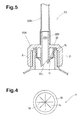
- the breakable partition wall 14 is, as shown in Fig.4, provided with at least three weakening grooves or lines 19 arranged in a radial pattern, namely, extending from the centre equiangularly around the centre.
- a small circular dent is formed at the centre and eight weakening lines 19 extend from the edge of the dent.
- the weakening lines 19 and dent have a depth (h) in a range of from 10 to 50 % of the thickness T of the breakable partition wall 14 (in this example about 0.3 mm).
- the above-mentioned outer cap 10 comprises a circular flat disc top 12 and a cylindrical skirt 13 the inside of which is threaded.
- the interior screw thread 13A of the skirt 13 engages the exterior screw thread 6A of the neck portion 6.
- the above-mentioned flange 16 of the inside plug 11 is fastened between the inside of the circular top 12 and the upper end of the neck portion 6, and functions as a gasket.
- the injector 20 comprises a flexible hose 20B and an adapter cap 20A.
- Fig.5 shows a state with the injector 20 attached to the bottle 2 instead of the outer cap 10.
- the adapter cap 20A comprises a cylindrical skirt 21 the inside of which is threaded, a circular disc top 22 at the upper edge of the cylindrical skirt 21, a coupling 22U protruding outwardly from the top 22 and tightly inserted in one end of the flexible hose 20B, a piercing pipe 22L protruding inwards from the inside of the top 22, and a through hole 22H extending from the inner end of the pipe 22L to the upper end of the coupling 22U.
- the interior screw thread of the skirt 21 engages the exterior screw thread 6A of the neck portion 6.
- the inner end of the pipe 22L is cut obliquely to provide a sharp edge so as to be able to break the weakening lines 19 easily and pierce the broken partition wall 14 by the motion due to screwing the adapter cap 20A onto the threaded neck.
- the hose 20B is constructed of a clear vinyl composition, e.g. polyvinyl chloride, and the size is for example as follows: inside diameter is 7 mm; outside diameter is 9 mm; and length about 100 to 150 mm.
- a clear vinyl composition e.g. polyvinyl chloride
- a plug 20C is put into the other end of the flexible hose 20B.
- the above-mentioned outer cap 10 and inside plug 11 can be made of thermoplastic resins which does not include gas barrier resin because the area exposed to the sealant S is small and the seal is double.
- the adapter cap 20A can be made of the same material as the outer cap 10.
- the inside plug 11 is made of polyethylene having elasticity so as to be able to function as a gasket as explained above.
- the bottle 2 in this example can be manufactured by first making a triple layered parison using a multilayer injection moulding machine and then blow moulding the parison using a biaxial-drawing blow-moulding machine. In this case, therefore, the entirety of the bottle 2 is formed with the triple layered structure.
- Table 1 shows test results. Bottles were made as above according to the specifications shown in Table 1, and their gas barrier property and withstanding pressure were measured as follows.
- Gas barrier property According to ASTM D3985, the oxygen permeability was measured at a temperature of 30 deg.C and relative humidity of 80 %. The smaller the value, the better the gas barrier property.
- Bottle Ref. Ex.1 Ex.2 Diameter D (mm) 86 86 86 Height H (mm) 120 120 120 Diameter d (mm) 32 32 32 32 Side wall Total thickness (mm) 1.0 1.0 1.0 1.0 1.0 1.0 1.0 1.0 1.0 1.0 1.0 1.0 1.0 1.0 1.0 1.0 1.0 1.0 1.0 1.0 1.0 1.0 1.0 1.0 1.0 1.0 1.0 1.0 1.0 1.0 1.0 1.0 1.0 1.0 1.0 1.0 1.0 1.0 1.0 1.0 1.0 1.0 1.0 1.0 1.0 1.0 1.0 1.0 1.0 1.0 1.0 1.0 1.0 1.0 1.0 1.0 1.0 1.0 1.0 1.0 1.0 1.0 1.0 1.0 1.0 1.0 1.0 1.0 1.0 1.0 1.0 1.0 1.0 1.0 1.0 1.0 1.0 1.0 1.0 1.0 1.0 1.0 1.0 1.0 1.0 1.0 1.0 1.0 1.0 1.0 1.0 1.0 1.0 1.0 1.0 1.0 1.0 1.0 1.0 1.0 1.0 1.0 1.0
- the diameter D of the bottle in the side wall is less than 60 mm, the amount of sealant transferred by one squeeze becomes too small and the operation time is excessive. Therefore, it is not preferable. If the diameter D is more than 90 mm, it becomes difficult to handle the bottle and obtain suitable resilience.
- ratio H/D of the height D of the side wall to the diameter D is less than 1.0, it becomes difficult to deform the side wall 5 due to the bottom 9 and funnel portion 7. If the ratio H/D is more than 1.5, it becomes difficult to obtain suitable resilience.
- the diameter (d) of the neck portion is less than 0.3 times the diameter D, it is difficult to make the bottle by blow moulding because the diameter difference is too large.
- a diameter (d) which is more than 0.5 times the diameter D is not preferable in view of the above-mentioned point (2).
- the usage of the puncture sealant set is as follows: remove the outer cap 10 from the bottle 2; attach the adapter cap 20A to the neck portion 6 by screwing - as a result, the inner end of the piercing pipe 22L breaks the partition wall 14 and the pipe 22L pierces the partition wall 14; remove the plug 20C from the flexible hose 20B to open the tip end; connect the open end of the flexible hose 20B to the air valve of a flat tyre; squeeze the bottle 2 by hand to inject the sealant into the tyre; remove the bottle from the tyre after the sealant is completely injected and put the plug 20C into the hose end; and immediately pump up the tyre and rotate the tyre for a certain time, usually about ten minutes, whereby the puncture wound is sealed by the sealant.
- the broken inside plug 11 is replaced with a new one, and the bottle 2 is reused by filling with new sealant. Also after expiration of the quality guaranteed term, the sealant can be replaced with new sealant, and not only the bottle 2 but also the inside plug 11 can be reused.
- the puncture sealant set according to the present invention may include a small-sized air pump for inflating the tyre which is operatable with a car battery.
- a small-sized air pump for inflating the tyre which is operatable with a car battery.
- Such pump is usually separate from the vehicle, but it may be integrated with the vehicle.
Landscapes
- Engineering & Computer Science (AREA)
- Mechanical Engineering (AREA)
- Closures For Containers (AREA)
- Laminated Bodies (AREA)
Abstract
Description
| Bottle | Ref. | Ex.1 | Ex.2 |
| Diameter D (mm) | 86 | 86 | 86 |
| Height H (mm) | 120 | 120 | 120 |
| Diameter d (mm) | 32 | 32 | 32 |
| Side wall | |||
| Total thickness (mm) | 1.0 | 1.0 | 1.0 |
| Inner layer | |||
| Material | LDPE | LDPE | LDPE |
| Thickness (mm) | 0.46 | 0.485 | |
| Middle layer | |||
| Material | LDPE | EVAL | EVAL |
| Thickness (mm) | 0.08 | 0.030 | |
| Outer layer | |||
| Material | LDPE | LDPE | LDPE |
| Thickness (mm) | 0.46 | 0.485 | |
| Gas barrier property (cc/day) | 6.1 | 0.05 | 0.23 |
| Withstand pressure (kpa) | 310 | 303 | 305 |
| *1) EVAL=Ethylene-vinylalcohol copolymer | |||
| *2) LDPE=Low-density polyethylene |
Claims (10)
- A tyre puncture sealant set comprising a bottle (2) having a body and a threaded neck portion (6) provided with an outlet (3), a puncture sealant (S) in the bottle, characterised by an inside plug (11) put in the outlet (3), an outer cap (10) screwed onto the neck portion (6) for covering the inside plug (11), an injector (20) replaceable with the outer cap (10), a side wall (5) of the body having a triple layered structure of an inner layer (5i), an outer layer (5o) and a middle layer (5m) therebetween made of a gas barrier resin so that the body (5) is squeezable by hand, the inside plug (11) being provided with a breakable partition wall (14) separating the inside of the bottle from the outside, the injector (20) comprising an adapter cap (20A) to be screwed onto the neck portion (3), a piercing pipe (22L) for piercing the breakable partition wall (14) into the inside of the bottle, and a hose (20B) for injecting the sealant (S) into a pneumatic tyre.
- A tyre puncture sealant set according to claim 1, characterised in that the outside diameter D of the body (5) of the bottle is in a range of from 60 to 90 mm, and the height H of the body (5) is in a range of from 1.0 to 1.5 times the diameter D.
- A tyre puncture sealant set according to claim 1 or 2, characterised in that the inner layer (5i) and outer layer (5o) are made of polyethylene, and the middle layer (5m) is made of a hydrolysed ethylene vinyl acetate copolymer.
- A tyre puncture sealant set according to claim 3, characterised in that the hydrolysed ethylene vinyl acetate copolymer is ethylene-vinylalcohol copolymer.
- A tyre puncture sealant set according to any of claims 1 to 4, characterised in that the bottle (2) is provided between the body (5) and the neck portion (3) with a funnel portion (7) being tapered from the body (5) to the neck portion (3).
- A storage container for tyre puncture sealant comprising a bottle (2) characterised by a manually squeezable body (5), a threaded neck portion (6) provided with an outlet (3), and a funnel portion (7) therebetween, an inside plug (11) to be put into the outlet (3), an outer cap (10) to be screwed onto the neck portion (6) for covering the inside plug (11), the inside plug (11) being provided with a breakable partition wall (14) separating the inside of the bottle from the outside, the breakable partition wall (14) being provided with weakening lines (19) arranged in a radial pattern, a side wall (5) of the body having a triple layered structure of an inner layer (5i), an outer layer (5o) and a middle layer (5m) therebetween made of a gas barrier resin.
- A storage container for tyre puncture sealant according to claim 7, characterised in that the inner layer (5i) and outer layer (5o) are made of polyethylene, and the middle layer (5m) is made of a hydrolysed ethylene vinyl acetate copolymer.
- A storage container for tyre puncture sealant according to claim 6 or 7, characterised by an injector (20) to be attached to the neck portion (6) instead of the outer cap (10) in a state that the inside plug (11) is put into the outlet, the injector (20) comprising an adapter cap (20A) to be screwed onto the neck portion (6), a piercing pipe (22L) for piercing the breakable partition wall (14) into the inside of the bottle, and a hose (20B) for injecting the sealant into a pneumatic tyre.
- A tyre puncture repair kit comprising a tyre puncture sealant set according to claim 1 and a tyre inflater.
- A tyre puncture repair kit according to claim 9, characterised in that the tyre inflater is an electric pump operatable with a car battery.
Applications Claiming Priority (2)
| Application Number | Priority Date | Filing Date | Title |
|---|---|---|---|
| JP2001220152 | 2001-07-19 | ||
| JP2001220152A JP3875523B2 (en) | 2001-07-19 | 2001-07-19 | Puncture sealant container and puncture repair system using the same |
Publications (2)
| Publication Number | Publication Date |
|---|---|
| EP1277669A1 true EP1277669A1 (en) | 2003-01-22 |
| EP1277669B1 EP1277669B1 (en) | 2006-03-08 |
Family
ID=19054014
Family Applications (1)
| Application Number | Title | Priority Date | Filing Date |
|---|---|---|---|
| EP02255056A Expired - Lifetime EP1277669B1 (en) | 2001-07-19 | 2002-07-18 | Tyre puncture sealant set |
Country Status (4)
| Country | Link |
|---|---|
| US (1) | US6668875B2 (en) |
| EP (1) | EP1277669B1 (en) |
| JP (1) | JP3875523B2 (en) |
| DE (1) | DE60209650T2 (en) |
Cited By (4)
| Publication number | Priority date | Publication date | Assignee | Title |
|---|---|---|---|---|
| CN100462290C (en) * | 2005-10-13 | 2009-02-18 | 千叶工业股份有限公司 | Raw material packaging structure of beverage container |
| EP2385895A4 (en) * | 2009-01-07 | 2017-12-13 | Trydel Research Pty. Ltd. | Apparatus for repairing and inflating of damaged inflatable articles |
| WO2020244515A1 (en) * | 2019-06-03 | 2020-12-10 | 彭晓峰 | Bottle cap of safety protection bottle |
| CN112357375A (en) * | 2020-11-17 | 2021-02-12 | 江苏威拉里新材料科技有限公司 | Metal powder vacuum collection device |
Families Citing this family (44)
| Publication number | Priority date | Publication date | Assignee | Title |
|---|---|---|---|---|
| DE10015166A1 (en) * | 2000-03-27 | 2001-10-04 | Dunlop Gmbh | Puncture repair device for tires comprises canister of sealant on to which adapter is screwed which has gas inlet and outlet which is applied to tire, ends of inlet and outlet nearest canister being fitted with valve opened by gas pressure |
| US7066724B2 (en) * | 2003-07-11 | 2006-06-27 | Urethane International Llc | Apparatus for flatproofing a tire and wheel assembly |
| US7105113B2 (en) * | 2003-07-11 | 2006-09-12 | Urethane International Llc | Method for flatproofing a tire and wheel assembly and resulting flatproofed assembly |
| JP2006062715A (en) * | 2004-08-27 | 2006-03-09 | Bridgestone Corp | Sealant storage and injecting container |
| EP1864786A1 (en) * | 2005-03-30 | 2007-12-12 | Bridgestone Corporation | Method of repairing inside surface portion of pneumatic tire, and relevant inside surface portion repair material |
| US7308915B2 (en) * | 2005-04-21 | 2007-12-18 | Jpro Dairy International, Inc. | Packaging system for storing and mixing separate ingredient components |
| EP1931576B1 (en) * | 2005-10-07 | 2012-04-25 | Rainer Ammann | Closure |
| US7635012B2 (en) * | 2006-06-12 | 2009-12-22 | Jpro Dairy International, Inc. | Sealed storage container with a coupling assembly |
| US7607460B2 (en) * | 2006-06-12 | 2009-10-27 | Jpro Dairy International, Inc. | Coupling assembly |
| USD607029S1 (en) * | 2006-11-27 | 2009-12-29 | Doukas Ag | Container for tire sealant with attached device for injecting tire sealant into vehicle tires |
| US8115615B2 (en) * | 2007-09-08 | 2012-02-14 | Ford Global Technologies | Status indicator and reminder system for vehicle temporary mobility kit |
| US8146622B2 (en) | 2007-08-20 | 2012-04-03 | Ford Global Technologies, Llc | Switch and hose-valve connection arrangement for vehicle temporary mobility kit |
| US8517760B2 (en) * | 2007-08-20 | 2013-08-27 | Ford Global Technologies, Llc | Cord wrap and power plug receptacle arrangement for inflator |
| US8981921B2 (en) | 2007-09-08 | 2015-03-17 | Ford Global Technologies, Llc | Status indicator and reminder system for vehicle temporary mobility kit |
| US8617333B2 (en) | 2007-09-20 | 2013-12-31 | The Goodyear Tire & Rubber Company | Pneumatic tire having built-in sealant layer and preparation thereof |
| US8316903B2 (en) * | 2007-10-01 | 2012-11-27 | The Goodyear Tire & Rubber Company | Pneumatic tire having built-in sealant layer and preparation thereof |
| JP5353280B2 (en) | 2008-03-25 | 2013-11-27 | 横浜ゴム株式会社 | Tire puncture repair equipment |
| US8226126B2 (en) * | 2009-08-24 | 2012-07-24 | Jpro Dairy International, Inc. | Bottle mixing assembly |
| CN102596548B (en) * | 2009-11-04 | 2015-04-22 | 住友橡胶工业株式会社 | Puncture repair kit |
| JP4743326B2 (en) | 2010-01-15 | 2011-08-10 | 横浜ゴム株式会社 | How to recover puncture repair liquid |
| TW201206818A (en) * | 2010-04-08 | 2012-02-16 | Abbott Lab | Bottle packaging for flowable product |
| USD638868S1 (en) * | 2010-06-07 | 2011-05-31 | Sumitomo Rubber Industries, Ltd. | Tire repair kit |
| USD638867S1 (en) * | 2010-06-07 | 2011-05-31 | Sumitomo Rubber Industries, Ltd. | Sealant bottle for tire repair kit |
| EP2639178A4 (en) * | 2010-11-10 | 2014-07-09 | Hee Kwon Rho | Sealing member for container |
| US9138946B2 (en) * | 2011-01-28 | 2015-09-22 | Sumitomo Rubber Industries, Ltd. | Flat tire repair kit |
| TWI482908B (en) * | 2011-03-07 | 2015-05-01 | 周文三 | Air compressor for vehicle |
| USD647930S1 (en) * | 2011-06-08 | 2011-11-01 | Sumitomo Rubber Industries, Ltd. | Sealant bottle for tire repair kit |
| USD648361S1 (en) * | 2011-06-10 | 2011-11-08 | Sumitomo Rubber Industries, Ltd. | Sealant bottle for tire repair kit |
| JP5568068B2 (en) * | 2011-09-20 | 2014-08-06 | 住友ゴム工業株式会社 | Punk repair kit |
| JP5333681B1 (en) * | 2011-10-11 | 2013-11-06 | 横浜ゴム株式会社 | Puncture repair liquid injection method and injection device |
| JP5568101B2 (en) * | 2012-02-03 | 2014-08-06 | 住友ゴム工業株式会社 | Integrated puncture repair kit |
| JP2013216329A (en) * | 2012-04-04 | 2013-10-24 | Yokohama Rubber Co Ltd:The | Liquid tire sealant container |
| CN104582941B (en) | 2012-08-31 | 2017-03-08 | 横浜橡胶株式会社 | Storage container for puncture repair agent |
| JP5656941B2 (en) * | 2012-08-31 | 2015-01-21 | キョーラク株式会社 | Storage container for puncture repair agent |
| US9193229B2 (en) * | 2013-12-03 | 2015-11-24 | Top Alliance Technology Limited | Tire repair device |
| JP6540255B2 (en) * | 2015-06-16 | 2019-07-10 | 住友ゴム工業株式会社 | Puncture repair kit |
| JP6511008B2 (en) * | 2016-05-10 | 2019-05-08 | 龍江精工株式会社 | Liquid container lid |
| USD823365S1 (en) * | 2017-03-31 | 2018-07-17 | Wong Wai Kan | Tire repair kit |
| JP6599414B2 (en) * | 2017-09-25 | 2019-10-30 | 龍江精工株式会社 | Liquid container lid |
| IT201900014586A1 (en) | 2019-08-09 | 2021-02-09 | Pumo Claudio Lo | SAFETY GROUP FOR TIRES |
| IT201900014574A1 (en) | 2019-08-09 | 2021-02-09 | Pumo Claudio Lo | SAFETY GROUP FOR TIRES |
| JP1731419S (en) * | 2022-04-06 | 2025-12-12 | Tire puncture repair tool connector | |
| KR102743339B1 (en) | 2022-12-08 | 2024-12-17 | 케이티 프로젝텐트윅렁스-게엠베하 | Tire repair device for attachment to a vehicle wheel |
| US12397517B2 (en) * | 2023-10-23 | 2025-08-26 | Unik World Industrial Co., Ltd. | Vehicle-mounted air compressor |
Citations (5)
| Publication number | Priority date | Publication date | Assignee | Title |
|---|---|---|---|---|
| US4049160A (en) * | 1975-09-08 | 1977-09-20 | Arnold Rumm | Flexible squeeze dispenser for liquid sealant |
| GB2102398A (en) * | 1981-06-17 | 1983-02-02 | Otk Keskusosuusliiki | Dispenser for fluids |
| US4795043A (en) * | 1986-11-06 | 1989-01-03 | Astra Plastique | Cap for container initially closed by a frangible lid |
| GB2206567A (en) * | 1988-08-09 | 1989-01-11 | Permabond Adhesives | Collapsible dispensing containers |
| GB2342347A (en) * | 1998-10-02 | 2000-04-12 | Unilever Plc | Closure for refill container |
Family Cites Families (11)
| Publication number | Priority date | Publication date | Assignee | Title |
|---|---|---|---|---|
| JPH0624352Y2 (en) * | 1984-11-09 | 1994-06-29 | 大成化工株式会社 | Extruded tube with blind lid |
| JPS61257306A (en) * | 1985-05-07 | 1986-11-14 | Manabu Yanaihara | Puncture mender by means of agglutinant injection |
| JPH0293204U (en) * | 1989-01-12 | 1990-07-24 | ||
| FR2729920B1 (en) * | 1995-02-01 | 1997-06-06 | Kerplas Snc | BOTTLE BODY AND BOTTLE FOR DISPENSING A PRODUCT |
| DE19549592C5 (en) * | 1995-07-11 | 2006-12-14 | Sumitomo Rubber Industries Ltd., Kobe | Device for sealing and inflating tires in the event of breakdowns |
| DE19625372B4 (en) * | 1996-06-25 | 2006-05-24 | Sumitomo Rubber Industries Ltd., Kobe | Method of removing puncture sealants from tires and apparatus for carrying out the method |
| DE19639707A1 (en) * | 1996-09-26 | 1998-04-02 | Sp Reifenwerke Gmbh | Tire sealing container for breakdowns |
| US5803310A (en) * | 1996-12-03 | 1998-09-08 | Soon; Min Tet | Bottle cap adaptable spout |
| US6053360A (en) * | 1998-07-01 | 2000-04-25 | Packaging Systems, Inc. | Fitment for a flexible container |
| JP3874953B2 (en) * | 1999-01-28 | 2007-01-31 | 株式会社吉野工業所 | Container with replacement bottle |
| US6670007B1 (en) * | 1999-04-07 | 2003-12-30 | Owens-Brockway Plastic Products Inc. | Multilayer container |
-
2001
- 2001-07-19 JP JP2001220152A patent/JP3875523B2/en not_active Expired - Fee Related
-
2002
- 2002-07-18 DE DE60209650T patent/DE60209650T2/en not_active Expired - Lifetime
- 2002-07-18 EP EP02255056A patent/EP1277669B1/en not_active Expired - Lifetime
- 2002-07-19 US US10/197,804 patent/US6668875B2/en not_active Expired - Lifetime
Patent Citations (5)
| Publication number | Priority date | Publication date | Assignee | Title |
|---|---|---|---|---|
| US4049160A (en) * | 1975-09-08 | 1977-09-20 | Arnold Rumm | Flexible squeeze dispenser for liquid sealant |
| GB2102398A (en) * | 1981-06-17 | 1983-02-02 | Otk Keskusosuusliiki | Dispenser for fluids |
| US4795043A (en) * | 1986-11-06 | 1989-01-03 | Astra Plastique | Cap for container initially closed by a frangible lid |
| GB2206567A (en) * | 1988-08-09 | 1989-01-11 | Permabond Adhesives | Collapsible dispensing containers |
| GB2342347A (en) * | 1998-10-02 | 2000-04-12 | Unilever Plc | Closure for refill container |
Cited By (4)
| Publication number | Priority date | Publication date | Assignee | Title |
|---|---|---|---|---|
| CN100462290C (en) * | 2005-10-13 | 2009-02-18 | 千叶工业股份有限公司 | Raw material packaging structure of beverage container |
| EP2385895A4 (en) * | 2009-01-07 | 2017-12-13 | Trydel Research Pty. Ltd. | Apparatus for repairing and inflating of damaged inflatable articles |
| WO2020244515A1 (en) * | 2019-06-03 | 2020-12-10 | 彭晓峰 | Bottle cap of safety protection bottle |
| CN112357375A (en) * | 2020-11-17 | 2021-02-12 | 江苏威拉里新材料科技有限公司 | Metal powder vacuum collection device |
Also Published As
| Publication number | Publication date |
|---|---|
| JP2003026217A (en) | 2003-01-29 |
| DE60209650T2 (en) | 2006-10-05 |
| JP3875523B2 (en) | 2007-01-31 |
| US20030024596A1 (en) | 2003-02-06 |
| EP1277669B1 (en) | 2006-03-08 |
| US6668875B2 (en) | 2003-12-30 |
| DE60209650D1 (en) | 2006-05-04 |
Similar Documents
| Publication | Publication Date | Title |
|---|---|---|
| US6668875B2 (en) | Tire puncture sealant set | |
| CA2303576C (en) | Multilayer container | |
| US6319453B1 (en) | Method of making a multiple neck spray bottle | |
| EP1266697B1 (en) | Separable laminated container | |
| EP1931509B1 (en) | Improvements in sealing apparatus | |
| US11542068B2 (en) | Tamper resistant device and methods of forming a tamper resistant device | |
| US8327897B2 (en) | Automatic tire sealing and inflating system | |
| KR20150048750A (en) | Preservation container for puncture repair agent | |
| CA2924280C (en) | Delamination container | |
| EP3444194B1 (en) | Method for manufacturing a delaminatable container | |
| US20060201967A1 (en) | Spout fitting for liquid-containing pouch | |
| JP5696979B2 (en) | Plastic container, long channel member and coating device | |
| US11247804B2 (en) | Multi-barrier bottles having tabbed preforms, and methods of forming the same | |
| US11434050B2 (en) | Stopper for a container for use in freeze-drying processes, and assembly of a stopper and a container | |
| KR20120096428A (en) | Plastic container, long flow member and coating apparatus | |
| US6886716B2 (en) | Cap with unitary security ring | |
| JP7645038B2 (en) | Tube container | |
| US20260077551A1 (en) | Container manufacturing method, double container manufacturing method, double container, and method for discharging contents from double container | |
| JP6540255B2 (en) | Puncture repair kit | |
| CN214297220U (en) | Liquid packaging bag discharge port nozzle with anti-theft function | |
| KR102350984B1 (en) | A medical cap and a container having the same | |
| JPH0891436A (en) | Composite container | |
| JP2006062715A (en) | Sealant storage and injecting container | |
| US20130233404A1 (en) | Method for recovering puncture repair liquid and apparatus for recovering puncture repair liquid | |
| JP2026000395A (en) | Double container, double container manufacturing method, double container use method |
Legal Events
| Date | Code | Title | Description |
|---|---|---|---|
| PUAI | Public reference made under article 153(3) epc to a published international application that has entered the european phase |
Free format text: ORIGINAL CODE: 0009012 |
|
| AK | Designated contracting states |
Kind code of ref document: A1 Designated state(s): AT BE BG CH CY CZ DE DK EE ES FI FR GB GR IE IT LI LU MC NL PT SE SK TR |
|
| AX | Request for extension of the european patent |
Free format text: AL;LT;LV;MK;RO;SI |
|
| 17P | Request for examination filed |
Effective date: 20030711 |
|
| AKX | Designation fees paid |
Designated state(s): DE FR GB |
|
| 17Q | First examination report despatched |
Effective date: 20050216 |
|
| GRAP | Despatch of communication of intention to grant a patent |
Free format text: ORIGINAL CODE: EPIDOSNIGR1 |
|
| GRAS | Grant fee paid |
Free format text: ORIGINAL CODE: EPIDOSNIGR3 |
|
| GRAA | (expected) grant |
Free format text: ORIGINAL CODE: 0009210 |
|
| AK | Designated contracting states |
Kind code of ref document: B1 Designated state(s): DE FR GB |
|
| REG | Reference to a national code |
Ref country code: GB Ref legal event code: FG4D |
|
| REF | Corresponds to: |
Ref document number: 60209650 Country of ref document: DE Date of ref document: 20060504 Kind code of ref document: P |
|
| ET | Fr: translation filed | ||
| PLBE | No opposition filed within time limit |
Free format text: ORIGINAL CODE: 0009261 |
|
| STAA | Information on the status of an ep patent application or granted ep patent |
Free format text: STATUS: NO OPPOSITION FILED WITHIN TIME LIMIT |
|
| 26N | No opposition filed |
Effective date: 20061211 |
|
| PGFP | Annual fee paid to national office [announced via postgrant information from national office to epo] |
Ref country code: GB Payment date: 20140716 Year of fee payment: 13 |
|
| GBPC | Gb: european patent ceased through non-payment of renewal fee |
Effective date: 20150718 |
|
| PG25 | Lapsed in a contracting state [announced via postgrant information from national office to epo] |
Ref country code: GB Free format text: LAPSE BECAUSE OF NON-PAYMENT OF DUE FEES Effective date: 20150718 |
|
| REG | Reference to a national code |
Ref country code: FR Ref legal event code: PLFP Year of fee payment: 15 |
|
| REG | Reference to a national code |
Ref country code: FR Ref legal event code: PLFP Year of fee payment: 16 |
|
| PGFP | Annual fee paid to national office [announced via postgrant information from national office to epo] |
Ref country code: FR Payment date: 20170613 Year of fee payment: 16 |
|
| PGFP | Annual fee paid to national office [announced via postgrant information from national office to epo] |
Ref country code: DE Payment date: 20170711 Year of fee payment: 16 |
|
| REG | Reference to a national code |
Ref country code: DE Ref legal event code: R119 Ref document number: 60209650 Country of ref document: DE |
|
| PG25 | Lapsed in a contracting state [announced via postgrant information from national office to epo] |
Ref country code: DE Free format text: LAPSE BECAUSE OF NON-PAYMENT OF DUE FEES Effective date: 20190201 Ref country code: FR Free format text: LAPSE BECAUSE OF NON-PAYMENT OF DUE FEES Effective date: 20180731 |