EP1277653A1 - Water jet propulsion outboard engine - Google Patents
Water jet propulsion outboard engine Download PDFInfo
- Publication number
- EP1277653A1 EP1277653A1 EP02712391A EP02712391A EP1277653A1 EP 1277653 A1 EP1277653 A1 EP 1277653A1 EP 02712391 A EP02712391 A EP 02712391A EP 02712391 A EP02712391 A EP 02712391A EP 1277653 A1 EP1277653 A1 EP 1277653A1
- Authority
- EP
- European Patent Office
- Prior art keywords
- water
- outboard motor
- exhaust
- jet propulsion
- duct member
- Prior art date
- Legal status (The legal status is an assumption and is not a legal conclusion. Google has not performed a legal analysis and makes no representation as to the accuracy of the status listed.)
- Withdrawn
Links
Images


Classifications
-
- B—PERFORMING OPERATIONS; TRANSPORTING
- B63—SHIPS OR OTHER WATERBORNE VESSELS; RELATED EQUIPMENT
- B63H—MARINE PROPULSION OR STEERING
- B63H20/00—Outboard propulsion units, e.g. outboard motors or Z-drives; Arrangements thereof on vessels
- B63H20/24—Arrangements, apparatus and methods for handling exhaust gas in outboard drives, e.g. exhaust gas outlets
- B63H20/245—Exhaust gas outlets
-
- B—PERFORMING OPERATIONS; TRANSPORTING
- B63—SHIPS OR OTHER WATERBORNE VESSELS; RELATED EQUIPMENT
- B63H—MARINE PROPULSION OR STEERING
- B63H11/00—Marine propulsion by water jets
- B63H11/02—Marine propulsion by water jets the propulsive medium being ambient water
- B63H11/04—Marine propulsion by water jets the propulsive medium being ambient water by means of pumps
- B63H11/08—Marine propulsion by water jets the propulsive medium being ambient water by means of pumps of rotary type
-
- B—PERFORMING OPERATIONS; TRANSPORTING
- B63—SHIPS OR OTHER WATERBORNE VESSELS; RELATED EQUIPMENT
- B63H—MARINE PROPULSION OR STEERING
- B63H11/00—Marine propulsion by water jets
- B63H11/02—Marine propulsion by water jets the propulsive medium being ambient water
- B63H11/10—Marine propulsion by water jets the propulsive medium being ambient water having means for deflecting jet or influencing cross-section thereof
- B63H11/107—Direction control of propulsive fluid
- B63H11/11—Direction control of propulsive fluid with bucket or clamshell-type reversing means
-
- B—PERFORMING OPERATIONS; TRANSPORTING
- B63—SHIPS OR OTHER WATERBORNE VESSELS; RELATED EQUIPMENT
- B63H—MARINE PROPULSION OR STEERING
- B63H20/00—Outboard propulsion units, e.g. outboard motors or Z-drives; Arrangements thereof on vessels
-
- B—PERFORMING OPERATIONS; TRANSPORTING
- B63—SHIPS OR OTHER WATERBORNE VESSELS; RELATED EQUIPMENT
- B63H—MARINE PROPULSION OR STEERING
- B63H20/00—Outboard propulsion units, e.g. outboard motors or Z-drives; Arrangements thereof on vessels
- B63H20/28—Arrangements, apparatus and methods for handling cooling-water in outboard drives, e.g. cooling-water intakes
- B63H20/285—Cooling-water intakes
-
- F—MECHANICAL ENGINEERING; LIGHTING; HEATING; WEAPONS; BLASTING
- F02—COMBUSTION ENGINES; HOT-GAS OR COMBUSTION-PRODUCT ENGINE PLANTS
- F02B—INTERNAL-COMBUSTION PISTON ENGINES; COMBUSTION ENGINES IN GENERAL
- F02B61/00—Adaptations of engines for driving vehicles or for driving propellers; Combinations of engines with gearing
- F02B61/04—Adaptations of engines for driving vehicles or for driving propellers; Combinations of engines with gearing for driving propellers
- F02B61/045—Adaptations of engines for driving vehicles or for driving propellers; Combinations of engines with gearing for driving propellers for marine engines
-
- B—PERFORMING OPERATIONS; TRANSPORTING
- B63—SHIPS OR OTHER WATERBORNE VESSELS; RELATED EQUIPMENT
- B63H—MARINE PROPULSION OR STEERING
- B63H11/00—Marine propulsion by water jets
- B63H11/02—Marine propulsion by water jets the propulsive medium being ambient water
- B63H11/04—Marine propulsion by water jets the propulsive medium being ambient water by means of pumps
- B63H11/08—Marine propulsion by water jets the propulsive medium being ambient water by means of pumps of rotary type
- B63H2011/081—Marine propulsion by water jets the propulsive medium being ambient water by means of pumps of rotary type with axial flow, i.e. the axis of rotation being parallel to the flow direction
Definitions
- the present invention relates to a water jet propulsion type outboard motor, in particular, to an improvement of a water anti-splash device also serving as a water intake unit for cooling water, an exhaust system for reducing exhaust noise, and a movable screen.
- Japanese Patent Application Laid-Open NO.9 (1997)-309492 discloses a water jet propulsion type outboard motor including an impeller that is housed within a duct having a suction port and a nozzle: water sucked from the suction port is pressurized with the impeller to be jetted out from the nozzle to propel a ship.
- the impeller of this outboard motor consists of axial flow blades, a thrust obtained with such an impeller is limited.
- the pressurized water in the duct is used as cooling water for an engine, sand flowing through the suction port gets mixed in with the cooling water for the engine.
- Japanese Patent Application Laid-Open NO.11 (1999)-286297 discloses a splashproof device for an outboard motor, in which a horizontal plate type splashboard is provided between the outboard motor and a ship so as to prevent an increase in running resistance caused by water striking against the outboard motor as well as to prevent water from splashing into the ship.
- this splashproof device is not capable of preventing water splashing from the stern from striking against a side face of the outboard motor when the outboard motor is rotated to change the running direction. Therefore, this splashproof device cannot prevent resistance from being increased.
- water striking against the side face of the outboard motor splashes into the ship.
- Japanese Patent Application Laid-Open NO.9 (1997)-39892 discloses a water jet propulsion type outboard motor, in which a swirl water flow pressurized with an impeller is conveyed to a volute casing to be jetted out from a discharge port so as to propel a ship.
- this outboard motor vertically sucks water from a suction port, there is a possibility that cavitation may occur due to negative pressure at the suction port while the ship is running.
- exhaust gas from an engine is directed to an underwater exhaust chamber, to which high-pressure water in the volute casing is supplied, so that energy of the exhaust gas is absorbed by the water so as to deaden the noise.
- the high-pressure water is supplied to the underwater exhaust chamber through a hole provided through the volute casing, energy loss is generated.
- Japanese Patent Application Laid-Open NO.8 (1996)-253196 discloses a screen for debris removal, which is fixed over an inlet port of a suction casing so as to prevent debris floating under the water and on the water surface from being sucked inside.
- this screen since this screen is fixed, it is necessary to remove screws, pins or the like which fix the screen in order to remove debris such as vinyl or cords passing through the screen and caught on an entry section of an impeller. Therefore, it is difficult to remove debris when a ship is on the water.
- the present invention has an object of providing a small and light-weight safety water jet propulsion type outboard motor with high propulsion efficiency.
- Another object of the present invention is to provide a water intake unit for preventing sand or the like from getting mixed with cooling water, an anti-splash device for preventing an increase in running resistance due to collision of a water flow splashing from a stern against a propulsion device and for preventing water from splashing into a ship, an exhaust system for reducing exhaust noise to lower the operation noise, and a movable screen for facilitating the removal of debris or the like.
- a water jet propulsion type outboard motor includes: a power source; a driving system for transmitting a driving power of the power source; a curved tubular duct member fixed to a housing on which the power source is mounted, having a suction port and a discharge port; guide blades provided within the duct member, in the vicinity of the discharge port thereof; and an impeller enclosed by the duct member and rotated by the driving system, wherein an outer peripheral edge of a spiral blade of the impeller provided around its hub is close to an inner peripheral face of the duct member, and an outer peripheral distal end portion of the impeller extends toward the suction port.
- the impeller since the impeller is enclosed within the duct member for protection, the impeller does not come into contact with obstacles such as sand or rocks. Therefore, according to the outboard motor including the impeller, the safe running of a ship can be provided even in shallows such as in the vicinity of a shoreline or on a river.
- the duct member has a curved tubular shape, a length of the duct member can be reduced, thereby reducing the outboard motor in size as well as in weight. Therefore, since the outboard motor does not protrude backward from the ship, the amount of band-shaped objects caught on the outboard motor or the contact with the driftwood or the like is decreased, thereby increasing the working rate and enhancing the safety of the outboard motor.
- the outer peripheral edge of a spiral blade is close to an inner peripheral face of the duct member so as to give an axially symmetrical energy to a fluid in a cross section vertical to a rotation axis of the impeller, balance efficiency is improved.
- the outer peripheral distal end portion of the spiral blade extends to the side of the suction port to form wide suction port and flow path of the impeller, floating objects are not caught on the spiral blade even when the floating objects flow into the duct member.
- the string or the like flows into the duct member, the string does not wind itself around the long blade face of the spiral blade. As a result, the suction performance is improved.
- a water jet propulsion type outboard motor is the outboard motor of the first aspect, wherein the outboard motor further includes a cooling water system for cooling the power source, including: a pump for pumping up water from outside; first and second water channel systems for guiding water from outside into the pump; and a third water channel system from the pump via the power source to the outside.
- a cooling water system for cooling the power source including: a pump for pumping up water from outside; first and second water channel systems for guiding water from outside into the pump; and a third water channel system from the pump via the power source to the outside.
- a water jet propulsion type outboard motor is the outboard motor according to the second aspect, wherein the first water channel system includes: a water suction port provided on an inner surface of the duct member between the impeller and the discharge port; a straight tubular path having the water intake port on its end, penetrating through the duct member; a first water channel branching from the straight tubular path, for guiding water into the pump; and a strainer provided in the straight tubular path so as to be detachable from the outside, and wherein the second water channel system includes: a water intake unit for taking in water from outside; and a second water channel for guiding water from the water intake unit into the pump.
- the cooling water system for cooling the power source includes two water channel systems for guiding cooling water into the pump, that is, the first and second water channel systems.
- the first water channel system takes water in through the water intake port provided on the inner wall of the duct member between the impeller and the discharge port, whereas the second water channel system takes water in from outside.
- the cooling water is mainly taken from the water intake port of the first water channel system.
- the strainer is provided in the straight tubular path penetrating through the duct member, the strainer is detachable from outside.
- a water jet propulsion type outboard motor is the outboard motor of the second aspect, wherein the outboard motor includes a water supply port for supplying running water to the first and second water channel systems.
- water can be supplied from the water supply port to the first and second water channel systems. Therefore, when the running water is connected to the water supply port during washing operation on land, running water can be easily supplied to the cooling water system to wash the power source of the cooling water system (for removal of a salt content, mud, sand or the like) and to cool the bearings of the impeller.
- a water jet propulsion type outboard motor is the outboard motor of the third aspect, wherein the outboard motor propels with the water intake unit of the second water channel system being juxtaposed with the inlet port of the duct member.
- the water intake unit since the water intake unit is juxtaposed with the suction port, the water intake unit is not affected by the suction of sand or the like into the duct member during the running of a ship.
- a water jet propulsion type outboard motor is the outboard motor of the third aspect, wherein the water intake unit of the second water channel system comprises an expanded water channel wider than the second water channel.
- the water intake unit since the water intake unit has an expanded water channel which is wider than the second water channel, water flowing into the water intake unit circulates and is retained within the expanded water channel before it can be sucked into the second water channel. At this time, sand or the like mixed with the flowing water precipitate within the expanded water channel to be separated from the water.
- a water jet propulsion type outboard motor is the outboard motor of the sixth aspect, wherein the water jet propulsion type outboard motor includes: an expanded water channel shell defining the expanded water channel; and a flat plate protruding outward from the expanded water channel shell, wherein the outboard motor propels with the flat plate being provided horizontally in the vicinity of the water surface.
- the flat plate protrudes outward from the expanded water channel shell and is horizontally provided in the vicinity of the water surface, the flat plate blocks a flow of splashing water so as to prevent water from splashing into a ship. Moreover, the flat plate reduces a running resistance of the ship so as to prevent the running speed from being lowered.
- a water jet propulsion type outboard motor is the outboard motor of the seventh aspect, the expanded water channel shell is provided with: a first opening for taking in water from outside; and a second opening communicated with the second water channel, wherein the outboard motor propels with the first opening being oriented downward.
- a water jet propulsion type outboard motor is the outboard motor of the eighth aspect, wherein a strainer is attached over the first opening.
- a water jet propulsion type outboard motor is the outboard motor of the eighth aspect, wherein the expanded water channel shell includes a pipe protruding inward provided on the second opening.
- a water jet propulsion type outboard motor is the outboard motor of the first aspect, wherein the outboard motor further includes an exhaust system for discharging exhaust gas from the power source to the outside, including: a first exhaust system provided within the housing, connected to the power source; and a second exhaust system for guiding exhaust gas to the outside, connected to the first exhaust system.
- a water jet propulsion type outboard motor is the outboard motor of the eleventh aspect, wherein the second exhaust system includes: an exhaust path provided around a surrounding wall of the duct member, connected to the first exhaust system; and an exhaust port in the vicinity of the discharge port of the duct member, wherein the outboard motor propels with the exhaust port being provided under the discharge port.
- a water jet propulsion type outboard motor is the outboard motor of the twelfth aspect, wherein the second exhaust system further includes a nozzle portion connected from the exhaust path to the exhaust port along the duct member, and wherein the outboard motor propels with the nozzle portion being provided on a bottom of the duct member.
- a water jet propulsion type outboard motor is the outboard motor of the eleventh aspect, wherein the second exhaust system includes: a plurality of expansion chambers connected to the first exhaust system; and an exhaust pipe connected to the expansion chamber, for discharging exhaust gas to the outside.
- a water jet propulsion type outboard motor is the outboard motor of the eleventh aspect, wherein the outboard motor further includes a cooling water system for cooling the power source, including: a water supply system for supplying water from outside into the power source; and a draining system for draining water from the power source to the outside, wherein the draining system and the exhaust system include a sump chamber for storing water from the draining system, and exhaust gas from the power source passes through the water stored in the sump chamber.
- a water jet propulsion type outboard motor is the outboard motor of the fifteenth aspect, wherein the water supply system is provided with a water supply port for supplying running water.
- a water jet propulsion type outboard motor is the outboard motor of the first aspect, wherein the outboard motor further includes: a screen swingably supported on a peripheral of the suction port; a flexible lever connected with the screen; and an engaging slot to be removably engaged with the lever; and wherein the outboard motor propels with the suction port of the duct member being oriented downward and a swing pivot of the screen being provided on a side of forward running.
- forward or front mean in a forward direction with respect to a running direction of a ship
- rear means in a backward direction with respect to the running direction of the ship.
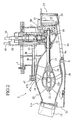
- an outboard motor 1 including an engine 2 serving as a power source, a housing 3 and a propulsion device 5, is removably attached to a transom 7a of a ship 7 through a bracket 6.
- the engine 2 is mounted to the housing 3, and the propulsion device 5 is provided to an attachment frame 4 connected to the housing 3 in a hanging condition.
- the operation of the engine 2 and the steering are performed by an operation lever 8.
- the propulsion device 5 includes a suction casing 9, a pump casing 10 and a discharge casing 11, which collectively serve as a duct member, a screen 44, an impeller 14, guide blades 22, and a reverser 23.
- the suction casing 9 includes a suction port 9a in the vicinity of a bottom 7b under the water, forming a curved tubular short suction duct 9b.
- the pump casing 10 is provided so as to be connected to the rear of the suction casing 9, enclosing the impeller 14.
- the discharge casing 11 is provided so as to be connected into the pump casing 10 and has a discharge port 11a which is open in a backward direction.
- the screen 44 is provided over the suction port 9a of the suction casing 9.
- the impeller 14 is fixed to a rear end of an impeller shaft 13 that is rotatably supported by a bearing 12 provided on an upper wall of a forward part of the suction casing 9 so as to be approximately horizontal and is provided so as to extend into the pump casing 10.
- a driving shaft 16 vertically extending from the engine 2 and the impeller shaft 13 which is provided approximately horizontal are inserted into a gear case 15 provided on the upper wall of the forward part of the suction casing 9. Then, a driving gear 17 fitted on a lower end of the driving shaft 16 and a driven gear 18 fitted on a forward end of the impeller shaft 13 mesh with each other within the gear case 15.
- the impeller 14 includes a hub 19 fixed to the impeller shaft 13 and a plurality of spiral blades 20 provided around the hub 19, as shown in FIG. 4.
- An outer peripheral edge 20b of the spiral blade 20 is close to an inner peripheral face of the pump casing 10 shown in FIG. 2.
- An outer peripheral distal end portion 20c of the spiral blade 20 extends to a rear end of the suction duct 9b of the suction casing 9, forming a long blade face 20a of the impeller 14.
- a plurality of guide blades 22 are provided around a blade boss 21 in which a bearing 12a supporting a rear end of the blade shaft 13 is provided.
- the guide blades 22 are connected to an inner surface of the discharge casing 11.
- the guide blades 22, the blade boss 21 and the discharge casing 11 form a plurality of ducts for straightening a swirl flow which is pressurized and accelerated with the impeller 14 into a linear flow.
- the blade boss 21, the hub 19, and the pump casing 10 and the discharge casing 11 constituting a barrel-shaped duct member, together define a curved flow path.
- the reverser 23 for reverse running is provided behind the discharge casing 11.
- the reverser 23 When the reverser 23 is vertically rotated by the operation lever 24 shown in FIG. 1, the reverser 23 covers the discharge port 11a to reverse a water jet flow jetted out from the discharge port 11a. As a result, the ship 7 runs in reverse.
- the cooling water system for cooling the engine 2 of the outboard motor 1 includes a cooling water pump 28 for pumping up water from outside of the outboard motor 1, a first water channel system and a second water channel system for guiding cooling water from outside of the outboard motor 1 to the cooling water pump 28, and a third water channel system 49 for guiding water from the cooling water pump 28 via the engine 2 to outside of the outboard motor 1.
- the first water channel system includes a water intake port 47a, a straight tubular path 47b having the water intake port 47a on one end, a cooling water pipe 48 serving as a first water channel, which branches from the straight tubular path 47b and guides water into the cooling water pump 28, and a strainer 47.
- the water intake port 47a has an opening on an inner surface positioned above the bearing 12a of the impeller 14, behind the pump casing 10 and between the impeller 14 and the discharge port 11a.
- the strainer 47 is provided within the straight tubular path 47b penetrating through the pump casing 10.
- the second water channel system includes an anti-splash box 25 serving as a water intake unit for taking in water from outside of the outboard motor 1, and a water channel 50 serving as a second water channel for guiding water from the anti-splash box 25 into the cooling water pump 28.
- a water supply port 51 is provided on the side of the propulsion device 5, and is connected to the first and second water channel systems.
- the anti-splash box 25 is provided between the outboard motor 1 and the ship 7, and is attached fixedly so as to be juxtaposed with the suction port 9a in front of the gear case 15 provided on the upper wall of the forward part of the suction casing 9.
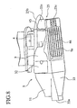
- the anti-splash box 25 includes a surrounding wall 25a serving as an expanded water channel shell, a brim-shaped manger board 25b (flat plate), a cooling water pipe 27 and a water intake 25c.
- the surrounding wall 25a has a semicylindrical wall on the front side of the anti-splash box 25, forming an expanded water channel which is wider than the water channel 50 (a cross-sectional area of a duct of the expanded water channel corresponds to 20 to 30 times of that of the water channel 50).
- the brim-shaped manger board 25b is attached fixedly to the anti-splash box 25 and protrudes over the forward to side parts of the surrounding wall 25a to be connected to a flange 4a of the attachment frame 4 of the propulsion device 5, as shown in FIG. 5.
- the water intake 25c is open on the bottom of the anti-splash box 25 in a downward direction.
- the strainer 26 is attached over the water intake 25c.
- the cooling water pipe 27 is vertically arranged to extend inward from the upper wall of the anti-splash box 25 and connected to the cooling water pump 28 of the engine 2.
- the exhaust system for discharging exhaust gas from the engine 2 to outside includes: an exhaust chamber 29 serving as a first exhaust system; an exhaust duct 31 serving as a second exhaust system connected to the exhaust chamber 29, for guiding exhaust gas to outside; and an exhaust path 32; a nozzle portion 33; and an exhaust port 33a.
- the exhaust chamber 29 is provided within the housing 3, and is connected to the engine 2. In the exhaust chamber 29, an exhaust cylinder 30 of the engine 2 is vertically provided in a hanging state.
- the exhaust duct 31 is provided for the attachment frame 4, and is connected to the bottom of the exhaust chamber 29.
- the exhaust path 32 is connected to the exhaust duct 31, and is provided around the surrounding wall of the suction casing 9.
- the nozzle portion 33 is connected to the exhaust path 32 along the bottom of the discharge casing 11, and is provided so as not to protrude downward beyond the inlet port 9a of the suction casing 9.
- the exhaust port 33a facing backward is opened in the vicinity of a lower side of the discharge port 11a of the discharge casing 11.
- the propulsion device 5 since the suction port 9a of the suction casing 9 is open in the vicinity of the bottom 7b of the ship, the propulsion device 5 does not protrude downward beyond the bottom 7b. Moreover, since the impeller 14 is enclosed within the casing of the propulsion device 5, the impeller 14 does not come into contact with obstacles such as sand or rocks. Therefore, the propulsion device 5 and the impeller 14 are not easily damaged, thereby providing safe running of a ship even in shallows such as in the vicinity of a shoreline or on a river.
- the propulsion device 5 Since the suction casing 9 forms the curved tubular short suction duct 9b, the propulsion device 5 is reduced in length, thereby reducing the outboard motor 1 in weight. Moreover, since the propulsion device 5 has a small length and therefore does not protrudes backward from the ship 7, the amount of band-shaped objects that wind themselves around the propulsion device 5 or the contact with the driftwood or the like is decreased, thereby increasing the working rate of the outboard motor 1.
- the outer peripheral edge 20b of the spiral blade 20 is close to the inner peripheral face of the pump casing 10 to give an axially symmetrical energy to a fluid in a cross section vertical to a rotation axis of the impeller 14, balance efficiency is improved.
- the outer peripheral distal end portion 20c of the spiral blade 20 extends to the rear end of the suction duct 9b of the suction casing 9 to form wide suction port and flow path of the impeller 14, floating objects are not caught on the spiral blade 20 even when the floating objects flow into the suction casing 9.
- the strings or the like flows into the suction casing 9, the strings does not wind itself around the long blade face 20a of the spiral blade 20. As a result, the suction performance is improved.
- the cooling water system for cooling the engine 2 of the outboard motor 1 includes two water channel systems for guiding cooling water into the cooling water pump 28, that is, the first and second water channel systems.
- the first water channel system takes water in through the water intake port 47a having an opening on the inner wall between the impeller 14 in the rear of the pump casing 10 and the discharge port 11a
- the second water channel system takes water in from the anti-splash box 25 attached fixedly so as to be juxtaposed with the suction port 9a in the forward part of the suction casing 9.
- a water pressure in the rear part of the pump casing 10 is increased by the rotation of the impeller 14.
- the cooling water for the engine 2 is mainly taken in from the water intake port 47a of the first water channel system.
- water is continuously supplied to the cooling water system because the cooling water pump 28 takes in water from the anti-splash box of the second water channel system instead.
- the burning out of the engine 2 can be prevented.
- strainer 47 Since the strainer 47 is provided over the straight tubular path 47b penetrating through the wall of the pump casing 10, the strainer 47 can be attached and removed from outside of the pump casing 10.
- the anti-splash box 25 Since the anti-splash box 25 is attached fixedly so as to be juxtaposed with the suction port 9a in front of the suction casing 9, the anti-splash box 25 is not affected by suction of sand or the like into the suction casing 9 during the running of the ship 7. Moreover, since the water intake 25c is open in a downward direction on the bottom of the anti-splash box 25, debris or the like hardly flows in through the water intake 25c while the ship 7 is running.
- the strainer 26 is provided over the water intake 25c, debris or the like is removed from water flowing into the anti-splash box 25. Furthermore, since the surrounding wall 25a of the anti-splash box 25 forms the expanded water channel which is wider than the water channel 50 of the second water channel system, the water flowing into the anti-splash box 25 circulates and is retained within the anti-splash box 25 before being sucked into the water channel 50. At this time, sand or the like mixed in with the flowing water precipitates within the anti-splash box 25 so as to be separated from the water. When the tip of the cooling water pipe 27 vertically arranged to extend inward from the upper wall of the anti-splash box 25 is placed in a stagnant flow region within the anti-splash box 25, the water without sand or the like can be efficiently taken.
- the water supply port 51 is provided on the side of the propulsion device 5, connected to the first and second water channel systems. Therefore, when running water is connected to the water supply port 51 during a washing operation on land, the running water can be easily supplied to the cooling water system to wash the engine 2 of the cooling water system (for removal of a salt content, mud, sand or the like) and to cool the bearing 12a of the impeller 14.
- the surrounding wall 25a of the anti-splash box 25 has a semicylindrical wall on the front side of the anti-splash box 25, water flow splashing from the stem 7c during the running of the ship 7 to strike against the surrounding wall 25a is pushed away to rear (an arrow in FIG. 5 indicates a water flow).
- the brim-shaped manger board 25b protrudes over the forward to the side parts of the surrounding wall 25a and is connected to the flange 4a of the attachment frame 4 of the propulsion device 5 to be horizontally provided in the vicinity of the water surface. Therefore, the manger board 25b blocks the flow of splashing water (arrows in FIG. 1 indicates a water flow) so as to prevent water from splashing into the propulsion device 5 and the ship.
- the manger board 25b reduces the running resistance of the ship to prevent the running speed from being lowered.
- the exhaust system includes the exhaust chamber 29, the exhaust duct 31, the exhaust path 32, the nozzle portion 33 and the exhaust port 33a, which are in successive connection with each other from the engine 2. An exhaust gas from the engine 2 passes through them to be discharged to outside.
- exhaust noise wave pressure fluctuation of the exhaust gas from the engine 2 (exhaust noise wave) is attenuated while the exhaust gas is flowing from the exhaust cylinder 30 into the exhaust chamber 29 to be expanded. Therefore, exhaust noise of the engine 2 is reduced.
- the nozzle portion 33 is provided along the bottom of the discharge casing 11 so as not to protrude downward beyond the suction port 9a of the suction casing 9, the nozzle portion 33 does not generate any water flow resistance during the running of the ship 7. Moreover, the side slipping is prevented, thus enhancing the straight running ability of the ship 7.
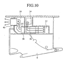
- a first expansion chamber 35, a second expansion chamber 37 and a third expansion chamber 39 are provided within the attachment frame 4.
- the first expansion chamber 35 is connected to the exhaust duct 31 through the exhaust port 34.
- the second expansion chamber 37 is connected to the first expansion chamber 35 through a first connection pipe 36.
- the third expansion chamber 39 is connected to the second expansion chamber 37 through a second connection pipe 38.
- An exhaust pipe 40 connected to the third expansion chamber 39, is open in a rear direction of the attachment frame 4 so as to discharge exhaust gas into the atmosphere or the water.
- exhaust gas from the engine 2 in FIG. 1 passes from the exhaust duct 31 through the exhaust port 34 to the first exhaust chamber 35, then, through the first connection pipe 36 to the second expansion chamber 37, and through the second connection pipe 38 to the third expansion chamber 39 in a successive manner.
- exhaust noise wave pressure fluctuation of the exhaust gas from the engine 2 (exhaust noise wave) is attenuated while the exhaust gas is flowing into the first expansion chamber 35 to be expanded. Thereafter, the exhaust gas is repeatedly expanded while successively flowing into the second expansion chamber 37 and further the third expansion chamber 39, so that pressure fluctuation is further attenuated.
- exhaust noise of the engine 2 is reduced.
- the outboard motor 1 can be compact.
- FIG. 11 and FIG. 12 The same elements as those in the first embodiment are denoted by the same reference numerals, and description thereof is omitted.
- a sump chamber 41 is provided within the attachment frame 4.
- the sump chamber 41 serves as a part of a draining system for draining the cooling water from the engine 2 shown in FIG. 1 to outside. At the same time, the sump chamber 41 also serves as a part of an exhaust system for discharging exhaust gas from the engine 2 to outside. Specifically, drain water of the cooling water flows down to be stored in the sump chamber 41 while the exhaust gas from the engine 2 passes through the sump chamber 41.
- a perforated plate 42 is attached on a partition wall between the exhaust duct 31 and the sump chamber 41.
- An exhaust path 43 connected to the sump chamber 41, has an opening in a rearward direction of the attachment frame 4 so as to discharge exhaust gas into the atmosphere or under the water.
- the exhaust gas from the engine 2 whose noise is attenuated in the exhaust chamber 29 shown in FIG. 7 passes from the exhaust duct 31 provided for the attachment frame 4 through the perforated plate 42 to flow into the sump chamber 41 so as to pass through the drain water stored in the sump chamber 41.
- a pressure fluctuation of the exhaust gas (exhaust noise wave) of the engine 2 is dissipated so that, in particular, higher harmonic waves (transmitted sound) are attenuated while the exhaust gas is passing through the drain water. Therefore, exhaust noise of the engine 2 is reduced and the operation noise is lowered.
- drain water can be stored in the sump chamber 41. In this manner, similar sound deadening effects as those obtained during the running of a ship can be obtained even during a washing operation on land.
- the screen 44 is hinged on the suction port 9a of the suction casing 9.
- a base end portion 44a of the screen 44 is swingably supported on a forward peripheral edge of the suction port 9a.
- a flexible lever 45 is connected to the base end portion 44a of the screen 44 and is removably engaged with an engaging slot 46 provided on the flange 4a extending from the bottom of the attachment frame 4 in FIG. 5 toward the side.
- the engaging slot 46 has a slot formed so that the lever 45 can be engaged therewith in a deflected state.
- the screen 44 is pushed against the peripheral edge of the suction port 9a of the suction casing 9 so as to be attached thereon.
- a conventional fixed type screen can be made movable in order to easily remove the debris or the like caught on the screen.
- a water jet propulsion type outboard motor of the present invention the length of a propulsion device can be reduced, thereby reducing the outboard motor in size as well as weight. Moreover, since an impeller is enclosed within a duct member, a ship can run safely even in shallows such as in the vicinity of a shoreline or on a river. Furthermore, spiral blades improve balance efficiency and suction performance of the impeller in order to obtain high thrust.
- a water intake unit for cooling water with an expanded water channel can prevent sand or the like from getting mixed in with cooling water.
- an exhaust system which guides the exhaust gas from a power source into the water under a discharge port of the duct member or into drain water in a sump chamber within an attachment frame, reduces the exhaust noise to a lower operation noise.
- a swingable screen to which a flexible lever is connected, is opened and closed during the running of a ship, debris or the like caught on the screen can be easily removed by water flow caused by running. Therefore, the outboard motor according to the present invention is useful as a water jet propulsion type outboard motor.
Landscapes
- Engineering & Computer Science (AREA)
- Ocean & Marine Engineering (AREA)
- Chemical & Material Sciences (AREA)
- Combustion & Propulsion (AREA)
- Mechanical Engineering (AREA)
- General Engineering & Computer Science (AREA)
- Exhaust Silencers (AREA)
- Jet Pumps And Other Pumps (AREA)
Abstract
A water jet propulsion type outboard motor (1) which includes: a power source
(2); a driving system; a housing (3); a curved tubular duct member (5); guide blades
(22); and an impeller (14). The duct member (5) is fixed to the housing (3) on which the
power source (2) is mounted, and having a suction port (9a) and a discharge port (11a).
The guide blades (22) are provided within the duct member in the vicinity of the
discharge port (11a) of the duct member (5). The impeller (14) is rotated by the driving
system for transmitting a driving power of the power source (2), and has a spiral blade
(20) with outer peripheral edge thereof close to an inner peripheral face of the duct
member (5), and outer peripheral distal end portion thereof extending toward the suction
port (9a).
Description
The present invention relates to a water jet propulsion type outboard motor, in
particular, to an improvement of a water anti-splash device also serving as a water intake
unit for cooling water, an exhaust system for reducing exhaust noise, and a movable
screen.
Japanese Patent Application Laid-Open NO.9 (1997)-309492 discloses a water
jet propulsion type outboard motor including an impeller that is housed within a duct
having a suction port and a nozzle: water sucked from the suction port is pressurized
with the impeller to be jetted out from the nozzle to propel a ship. However, since the
impeller of this outboard motor consists of axial flow blades, a thrust obtained with such
an impeller is limited. Moreover, since the pressurized water in the duct is used as
cooling water for an engine, sand flowing through the suction port gets mixed in with the
cooling water for the engine.
Japanese Patent Application Laid-Open NO.11 (1999)-286297 discloses a
splashproof device for an outboard motor, in which a horizontal plate type splashboard is
provided between the outboard motor and a ship so as to prevent an increase in running
resistance caused by water striking against the outboard motor as well as to prevent
water from splashing into the ship. However, this splashproof device is not capable of
preventing water splashing from the stern from striking against a side face of the
outboard motor when the outboard motor is rotated to change the running direction.
Therefore, this splashproof device cannot prevent resistance from being increased.
Moreover, water striking against the side face of the outboard motor splashes into the
ship.
Japanese Patent Application Laid-Open NO.9 (1997)-39892 discloses a water
jet propulsion type outboard motor, in which a swirl water flow pressurized with an
impeller is conveyed to a volute casing to be jetted out from a discharge port so as to
propel a ship. However, since this outboard motor vertically sucks water from a suction
port, there is a possibility that cavitation may occur due to negative pressure at the
suction port while the ship is running. Moreover, exhaust gas from an engine is directed
to an underwater exhaust chamber, to which high-pressure water in the volute casing is
supplied, so that energy of the exhaust gas is absorbed by the water so as to deaden the
noise. However, since the high-pressure water is supplied to the underwater exhaust
chamber through a hole provided through the volute casing, energy loss is generated.
Japanese Patent Application Laid-Open NO.8 (1996)-253196 discloses a
screen for debris removal, which is fixed over an inlet port of a suction casing so as to
prevent debris floating under the water and on the water surface from being sucked
inside. However, since this screen is fixed, it is necessary to remove screws, pins or the
like which fix the screen in order to remove debris such as vinyl or cords passing
through the screen and caught on an entry section of an impeller. Therefore, it is
difficult to remove debris when a ship is on the water.
In view of the conventional problems as described above, the present invention
has an object of providing a small and light-weight safety water jet propulsion type
outboard motor with high propulsion efficiency.
Another object of the present invention is to provide a water intake unit for
preventing sand or the like from getting mixed with cooling water, an anti-splash device
for preventing an increase in running resistance due to collision of a water flow
splashing from a stern against a propulsion device and for preventing water from
splashing into a ship, an exhaust system for reducing exhaust noise to lower the
operation noise, and a movable screen for facilitating the removal of debris or the like.
In order to achieve the above objects, a water jet propulsion type outboard
motor according to a first aspect of the present invention includes: a power source; a
driving system for transmitting a driving power of the power source; a curved tubular
duct member fixed to a housing on which the power source is mounted, having a suction
port and a discharge port; guide blades provided within the duct member, in the vicinity
of the discharge port thereof; and an impeller enclosed by the duct member and rotated
by the driving system, wherein an outer peripheral edge of a spiral blade of the impeller
provided around its hub is close to an inner peripheral face of the duct member, and an
outer peripheral distal end portion of the impeller extends toward the suction port.
In the above structure, since the impeller is enclosed within the duct member
for protection, the impeller does not come into contact with obstacles such as sand or
rocks. Therefore, according to the outboard motor including the impeller, the safe
running of a ship can be provided even in shallows such as in the vicinity of a shoreline
or on a river.
Moreover, since the duct member has a curved tubular shape, a length of the
duct member can be reduced, thereby reducing the outboard motor in size as well as in
weight. Therefore, since the outboard motor does not protrude backward from the ship,
the amount of band-shaped objects caught on the outboard motor or the contact with the
driftwood or the like is decreased, thereby increasing the working rate and enhancing the
safety of the outboard motor.
Since the outer peripheral edge of a spiral blade is close to an inner peripheral
face of the duct member so as to give an axially symmetrical energy to a fluid in a cross
section vertical to a rotation axis of the impeller, balance efficiency is improved.
Moreover, the outer peripheral distal end portion of the spiral blade extends to the side
of the suction port to form wide suction port and flow path of the impeller, floating
objects are not caught on the spiral blade even when the floating objects flow into the
duct member. Moreover, even when string or the like flows into the duct member, the
string does not wind itself around the long blade face of the spiral blade. As a result, the
suction performance is improved.
A water jet propulsion type outboard motor according to a second aspect of the
present invention is the outboard motor of the first aspect, wherein the outboard motor
further includes a cooling water system for cooling the power source, including: a pump
for pumping up water from outside; first and second water channel systems for guiding
water from outside into the pump; and a third water channel system from the pump via
the power source to the outside.
A water jet propulsion type outboard motor according to a third aspect of the
present invention is the outboard motor according to the second aspect, wherein the first
water channel system includes: a water suction port provided on an inner surface of the
duct member between the impeller and the discharge port; a straight tubular path having
the water intake port on its end, penetrating through the duct member; a first water
channel branching from the straight tubular path, for guiding water into the pump; and a
strainer provided in the straight tubular path so as to be detachable from the outside, and
wherein the second water channel system includes: a water intake unit for taking in
water from outside; and a second water channel for guiding water from the water intake
unit into the pump.
In the above structure, the cooling water system for cooling the power source
includes two water channel systems for guiding cooling water into the pump, that is, the
first and second water channel systems. The first water channel system takes water in
through the water intake port provided on the inner wall of the duct member between the
impeller and the discharge port, whereas the second water channel system takes water in
from outside. During the normal running of the ship, water pressure within the duct
member between the impeller and the discharge port is increased by the rotation of the
impeller. Thus, the cooling water is mainly taken from the water intake port of the first
water channel system. During the running of the ship in shallows, even when sand or
the like is sucked into the duct member so as to cause clogging of the strainer provided
for the straight tubular path extending from the water intake port, making it difficult to
take water in through the water intake port of the first water channel system, water is
continuously supplied to the cooling water system because the pump takes water in from
the water intake unit of the second water channel system instead. Thus, the burning out
of the power source can be prevented.
Moreover, since the strainer is provided in the straight tubular path penetrating
through the duct member, the strainer is detachable from outside.
A water jet propulsion type outboard motor according to a fourth aspect of the
present invention is the outboard motor of the second aspect, wherein the outboard
motor includes a water supply port for supplying running water to the first and second
water channel systems.
In the above structure, water can be supplied from the water supply port to the
first and second water channel systems. Therefore, when the running water is connected
to the water supply port during washing operation on land, running water can be easily
supplied to the cooling water system to wash the power source of the cooling water
system (for removal of a salt content, mud, sand or the like) and to cool the bearings of
the impeller.
A water jet propulsion type outboard motor according to a fifth aspect of the
present invention is the outboard motor of the third aspect, wherein the outboard motor
propels with the water intake unit of the second water channel system being juxtaposed
with the inlet port of the duct member.
In the above structure, since the water intake unit is juxtaposed with the
suction port, the water intake unit is not affected by the suction of sand or the like into
the duct member during the running of a ship.
A water jet propulsion type outboard motor according to a sixth aspect of the
present invention is the outboard motor of the third aspect, wherein the water intake unit
of the second water channel system comprises an expanded water channel wider than the
second water channel.
In the above structure, since the water intake unit has an expanded water
channel which is wider than the second water channel, water flowing into the water
intake unit circulates and is retained within the expanded water channel before it can be
sucked into the second water channel. At this time, sand or the like mixed with the
flowing water precipitate within the expanded water channel to be separated from the
water.
A water jet propulsion type outboard motor according to a seventh aspect of
the present invention is the outboard motor of the sixth aspect, wherein the water jet
propulsion type outboard motor includes: an expanded water channel shell defining the
expanded water channel; and a flat plate protruding outward from the expanded water
channel shell, wherein the outboard motor propels with the flat plate being provided
horizontally in the vicinity of the water surface.
In the above structure, since the flat plate protrudes outward from the
expanded water channel shell and is horizontally provided in the vicinity of the water
surface, the flat plate blocks a flow of splashing water so as to prevent water from
splashing into a ship. Moreover, the flat plate reduces a running resistance of the ship so
as to prevent the running speed from being lowered.
A water jet propulsion type outboard motor according to an eighth aspect of
the present invention is the outboard motor of the seventh aspect, the expanded water
channel shell is provided with: a first opening for taking in water from outside; and a
second opening communicated with the second water channel, wherein the outboard
motor propels with the first opening being oriented downward.
In the above structure, since the first opening of the expanded water channel
shell is oriented downward, debris or the like do not easily flow into the water intake
unit while the ship is running.
A water jet propulsion type outboard motor according to a ninth aspect of the
present invention is the outboard motor of the eighth aspect, wherein a strainer is
attached over the first opening.
A water jet propulsion type outboard motor according to a tenth aspect of the
present invention is the outboard motor of the eighth aspect, wherein the expanded water
channel shell includes a pipe protruding inward provided on the second opening.
In the above structure, since a strainer is attached over the first opening, debris
or the like is removed from water flowing into the water intake unit. Moreover, when a
tip of the pipe protruding inward provided on the second opening of the expanded water
channel shell is placed in a stagnant flow region within the expanded water channel,
water without sand or the like can be efficiently taken in.
A water jet propulsion type outboard motor according to an eleventh aspect of
the present invention is the outboard motor of the first aspect, wherein the outboard
motor further includes an exhaust system for discharging exhaust gas from the power
source to the outside, including: a first exhaust system provided within the housing,
connected to the power source; and a second exhaust system for guiding exhaust gas to
the outside, connected to the first exhaust system.
A water jet propulsion type outboard motor according to a twelfth aspect of
the present invention is the outboard motor of the eleventh aspect, wherein the second
exhaust system includes: an exhaust path provided around a surrounding wall of the duct
member, connected to the first exhaust system; and an exhaust port in the vicinity of the
discharge port of the duct member, wherein the outboard motor propels with the exhaust
port being provided under the discharge port.
In the above structure, since the exhaust port is open in the vicinity of a lower
side of the discharge port, the exhaust gas from the power source is released under water.
A pressure fluctuation of the exhaust gas (exhaust noise wave) of the power source is
dissipated so as to be attenuated while the exhaust gas is passing through the water.
Therefore, exhaust noise of the power source is reduced.
A water jet propulsion type outboard motor according to a thirteenth aspect of
the present invention is the outboard motor of the twelfth aspect, wherein the second
exhaust system further includes a nozzle portion connected from the exhaust path to the
exhaust port along the duct member, and wherein the outboard motor propels with the
nozzle portion being provided on a bottom of the duct member.
In the above structure, since the nozzle portion is provided along the bottom of
the duct member, the side slipping of a ship is prevented, thus enhancing the straight
running ability of the ship.
A water jet propulsion type outboard motor according to a fourteenth aspect of
the present invention is the outboard motor of the eleventh aspect, wherein the second
exhaust system includes: a plurality of expansion chambers connected to the first
exhaust system; and an exhaust pipe connected to the expansion chamber, for
discharging exhaust gas to the outside.
In the above structure, when exhaust gas from the power source successively
flows into a plurality of expansion chambers to be repeatedly expanded therein, and
pressure fluctuation of the exhaust gas (exhaust noise wave) is gradually attenuated.
Thus, exhaust noise of the power source is reduced.
A water jet propulsion type outboard motor according to a fifteenth aspect of
the present invention is the outboard motor of the eleventh aspect, wherein the outboard
motor further includes a cooling water system for cooling the power source, including: a
water supply system for supplying water from outside into the power source; and a
draining system for draining water from the power source to the outside, wherein the
draining system and the exhaust system include a sump chamber for storing water from
the draining system, and exhaust gas from the power source passes through the water
stored in the sump chamber.
In the above structure, when the exhaust gas from the power source passes
through the water stored in the sump chamber, pressure fluctuation of the exhaust gas
(exhaust gas wave) of the engine is dissipated, so that in particular, higher harmonic
waves (transmitting sound) is attenuated. Therefore, exhaust noise of the engine is
reduced, and the operation noise is lowered.
A water jet propulsion type outboard motor according to a sixteenth aspect of
the present invention is the outboard motor of the fifteenth aspect, wherein the water
supply system is provided with a water supply port for supplying running water.
In the above structure, if running water is supplied from the water supply port,
water can be stored in the sump chamber. Thus, similar sound deadening effects as
those obtained during the running of the ship can be obtained even during the washing
operation on land.
A water jet propulsion type outboard motor according to a seventeenth aspect
of the present invention is the outboard motor of the first aspect, wherein the outboard
motor further includes: a screen swingably supported on a peripheral of the suction port;
a flexible lever connected with the screen; and an engaging slot to be removably
engaged with the lever; and wherein the outboard motor propels with the suction port of
the duct member being oriented downward and a swing pivot of the screen being
provided on a side of forward running.
In the above structure, when the lever is disengaged from the engaging slot so
that the screen is separated from the suction port during the running of a ship, debris or
the like caught on the screen can be swept away by a water flow caused by the running
of the ship. If the lever is engaged with the engaging slot in a deflected state, the screen
can be pushed against the inlet port to be attached thereon.
In the accompanying drawings:
Hereinafter, embodiments of the present invention will be described in detail
with reference to the accompanying drawings. In the following description, the terms
"forward" or "front" mean in a forward direction with respect to a running direction of a
ship, and "rear", "backward" or "reverse" mean in a backward direction with respect to
the running direction of the ship.
As shown in FIG. 1, an outboard motor 1 including an engine 2 serving as a
power source, a housing 3 and a propulsion device 5, is removably attached to a transom
7a of a ship 7 through a bracket 6.
The engine 2 is mounted to the housing 3, and the propulsion device 5 is
provided to an attachment frame 4 connected to the housing 3 in a hanging condition.
The operation of the engine 2 and the steering are performed by an operation lever 8.
As shown in FIG. 2 and FIG. 3, the propulsion device 5 includes a suction
casing 9, a pump casing 10 and a discharge casing 11, which collectively serve as a duct
member, a screen 44, an impeller 14, guide blades 22, and a reverser 23.
The suction casing 9 includes a suction port 9a in the vicinity of a bottom 7b
under the water, forming a curved tubular short suction duct 9b. The pump casing 10 is
provided so as to be connected to the rear of the suction casing 9, enclosing the impeller
14. The discharge casing 11 is provided so as to be connected into the pump casing 10
and has a discharge port 11a which is open in a backward direction.
The screen 44 is provided over the suction port 9a of the suction casing 9.
The impeller 14 is fixed to a rear end of an impeller shaft 13 that is rotatably
supported by a bearing 12 provided on an upper wall of a forward part of the suction
casing 9 so as to be approximately horizontal and is provided so as to extend into the
pump casing 10.
A driving shaft 16 vertically extending from the engine 2 and the impeller
shaft 13 which is provided approximately horizontal are inserted into a gear case 15
provided on the upper wall of the forward part of the suction casing 9. Then, a driving
gear 17 fitted on a lower end of the driving shaft 16 and a driven gear 18 fitted on a
forward end of the impeller shaft 13 mesh with each other within the gear case 15.
As a result, a driving power of the engine 2 is transmitted from the driving
shaft 16 to the impeller shaft 13 to rotate the impeller 14.
The impeller 14 includes a hub 19 fixed to the impeller shaft 13 and a plurality
of spiral blades 20 provided around the hub 19, as shown in FIG. 4. An outer peripheral
edge 20b of the spiral blade 20 is close to an inner peripheral face of the pump casing 10
shown in FIG. 2. An outer peripheral distal end portion 20c of the spiral blade 20
extends to a rear end of the suction duct 9b of the suction casing 9, forming a long blade
face 20a of the impeller 14.
A plurality of guide blades 22 are provided around a blade boss 21 in which a
bearing 12a supporting a rear end of the blade shaft 13 is provided. The guide blades 22
are connected to an inner surface of the discharge casing 11. The guide blades 22, the
blade boss 21 and the discharge casing 11 form a plurality of ducts for straightening a
swirl flow which is pressurized and accelerated with the impeller 14 into a linear flow.
The blade boss 21, the hub 19, and the pump casing 10 and the discharge casing 11
constituting a barrel-shaped duct member, together define a curved flow path.
The reverser 23 for reverse running is provided behind the discharge casing 11.
When the reverser 23 is vertically rotated by the operation lever 24 shown in FIG. 1, the
reverser 23 covers the discharge port 11a to reverse a water jet flow jetted out from the
discharge port 11a. As a result, the ship 7 runs in reverse.
Next, a cooling water system for cooling the engine 2 of the outboard motor 1
will be described with reference to FIG. 1 to FIG. 6.
The cooling water system for cooling the engine 2 of the outboard motor 1
includes a cooling water pump 28 for pumping up water from outside of the outboard
motor 1, a first water channel system and a second water channel system for guiding
cooling water from outside of the outboard motor 1 to the cooling water pump 28, and a
third water channel system 49 for guiding water from the cooling water pump 28 via the
engine 2 to outside of the outboard motor 1.
The first water channel system includes a water intake port 47a, a straight
tubular path 47b having the water intake port 47a on one end, a cooling water pipe 48
serving as a first water channel, which branches from the straight tubular path 47b and
guides water into the cooling water pump 28, and a strainer 47.
The water intake port 47a has an opening on an inner surface positioned above
the bearing 12a of the impeller 14, behind the pump casing 10 and between the impeller
14 and the discharge port 11a. The strainer 47 is provided within the straight tubular
path 47b penetrating through the pump casing 10.
The second water channel system includes an anti-splash box 25 serving as a
water intake unit for taking in water from outside of the outboard motor 1, and a water
channel 50 serving as a second water channel for guiding water from the anti-splash box
25 into the cooling water pump 28.
As shown in FIG. 1, a water supply port 51 is provided on the side of the
propulsion device 5, and is connected to the first and second water channel systems.
The anti-splash box 25 is provided between the outboard motor 1 and the ship
7, and is attached fixedly so as to be juxtaposed with the suction port 9a in front of the
gear case 15 provided on the upper wall of the forward part of the suction casing 9. The
anti-splash box 25 includes a surrounding wall 25a serving as an expanded water
channel shell, a brim-shaped manger board 25b (flat plate), a cooling water pipe 27 and
a water intake 25c.
The surrounding wall 25a has a semicylindrical wall on the front side of the
anti-splash box 25, forming an expanded water channel which is wider than the water
channel 50 (a cross-sectional area of a duct of the expanded water channel corresponds
to 20 to 30 times of that of the water channel 50).
The brim-shaped manger board 25b is attached fixedly to the anti-splash box
25 and protrudes over the forward to side parts of the surrounding wall 25a to be
connected to a flange 4a of the attachment frame 4 of the propulsion device 5, as shown
in FIG. 5.
As shown in FIG. 6, the water intake 25c is open on the bottom of the anti-splash
box 25 in a downward direction. The strainer 26 is attached over the water intake
25c.
The cooling water pipe 27 is vertically arranged to extend inward from the
upper wall of the anti-splash box 25 and connected to the cooling water pump 28 of the
engine 2.
Next, the exhaust system for discharging exhaust gas from the engine 2 of the
outboard motor 1 to outside will be described based on FIG. 7 and FIG. 8.
As shown in FIG. 7 and FIG. 8, the exhaust system for discharging exhaust
gas from the engine 2 to outside includes: an exhaust chamber 29 serving as a first
exhaust system; an exhaust duct 31 serving as a second exhaust system connected to the
exhaust chamber 29, for guiding exhaust gas to outside; and an exhaust path 32; a nozzle
portion 33; and an exhaust port 33a.
The exhaust chamber 29 is provided within the housing 3, and is connected to
the engine 2. In the exhaust chamber 29, an exhaust cylinder 30 of the engine 2 is
vertically provided in a hanging state.
The exhaust duct 31 is provided for the attachment frame 4, and is connected
to the bottom of the exhaust chamber 29.
The exhaust path 32 is connected to the exhaust duct 31, and is provided
around the surrounding wall of the suction casing 9.
The nozzle portion 33 is connected to the exhaust path 32 along the bottom of
the discharge casing 11, and is provided so as not to protrude downward beyond the inlet
port 9a of the suction casing 9.
The exhaust port 33a facing backward is opened in the vicinity of a lower side
of the discharge port 11a of the discharge casing 11.
According to the first embodiment, since the suction port 9a of the suction
casing 9 is open in the vicinity of the bottom 7b of the ship, the propulsion device 5 does
not protrude downward beyond the bottom 7b. Moreover, since the impeller 14 is
enclosed within the casing of the propulsion device 5, the impeller 14 does not come into
contact with obstacles such as sand or rocks. Therefore, the propulsion device 5 and the
impeller 14 are not easily damaged, thereby providing safe running of a ship even in
shallows such as in the vicinity of a shoreline or on a river.
Since the suction casing 9 forms the curved tubular short suction duct 9b, the
propulsion device 5 is reduced in length, thereby reducing the outboard motor 1 in
weight. Moreover, since the propulsion device 5 has a small length and therefore does
not protrudes backward from the ship 7, the amount of band-shaped objects that wind
themselves around the propulsion device 5 or the contact with the driftwood or the like
is decreased, thereby increasing the working rate of the outboard motor 1.
Furthermore, since the outer peripheral edge 20b of the spiral blade 20 is close
to the inner peripheral face of the pump casing 10 to give an axially symmetrical energy
to a fluid in a cross section vertical to a rotation axis of the impeller 14, balance
efficiency is improved. Moreover, the outer peripheral distal end portion 20c of the
spiral blade 20 extends to the rear end of the suction duct 9b of the suction casing 9 to
form wide suction port and flow path of the impeller 14, floating objects are not caught
on the spiral blade 20 even when the floating objects flow into the suction casing 9.
Moreover, even when strings or the like flows into the suction casing 9, the strings does
not wind itself around the long blade face 20a of the spiral blade 20. As a result, the
suction performance is improved.
The cooling water system for cooling the engine 2 of the outboard motor 1
includes two water channel systems for guiding cooling water into the cooling water
pump 28, that is, the first and second water channel systems. The first water channel
system takes water in through the water intake port 47a having an opening on the inner
wall between the impeller 14 in the rear of the pump casing 10 and the discharge port
11a, whereas the second water channel system takes water in from the anti-splash box 25
attached fixedly so as to be juxtaposed with the suction port 9a in the forward part of the
suction casing 9. During the normal running of the ship 7, a water pressure in the rear
part of the pump casing 10 is increased by the rotation of the impeller 14. Thus, the
cooling water for the engine 2 is mainly taken in from the water intake port 47a of the
first water channel system. During running of the ship 7 in shallows, even when sand or
the like is sucked into the suction casing 9 so as to cause clogging of the strainer 47
provided over the straight tubular path 47b extending from the water intake port 47a,
making it difficult to take in water through the water intake port 47a of the first water
channel system, water is continuously supplied to the cooling water system because the
cooling water pump 28 takes in water from the anti-splash box of the second water
channel system instead. Thus, the burning out of the engine 2 can be prevented.
Since the strainer 47 is provided over the straight tubular path 47b penetrating
through the wall of the pump casing 10, the strainer 47 can be attached and removed
from outside of the pump casing 10.
Since the anti-splash box 25 is attached fixedly so as to be juxtaposed with the
suction port 9a in front of the suction casing 9, the anti-splash box 25 is not affected by
suction of sand or the like into the suction casing 9 during the running of the ship 7.
Moreover, since the water intake 25c is open in a downward direction on the bottom of
the anti-splash box 25, debris or the like hardly flows in through the water intake 25c
while the ship 7 is running.
Since the strainer 26 is provided over the water intake 25c, debris or the like is
removed from water flowing into the anti-splash box 25. Furthermore, since the
surrounding wall 25a of the anti-splash box 25 forms the expanded water channel which
is wider than the water channel 50 of the second water channel system, the water
flowing into the anti-splash box 25 circulates and is retained within the anti-splash box
25 before being sucked into the water channel 50. At this time, sand or the like mixed in
with the flowing water precipitates within the anti-splash box 25 so as to be separated
from the water. When the tip of the cooling water pipe 27 vertically arranged to extend
inward from the upper wall of the anti-splash box 25 is placed in a stagnant flow region
within the anti-splash box 25, the water without sand or the like can be efficiently taken.
The water supply port 51 is provided on the side of the propulsion device 5,
connected to the first and second water channel systems. Therefore, when running water
is connected to the water supply port 51 during a washing operation on land, the running
water can be easily supplied to the cooling water system to wash the engine 2 of the
cooling water system (for removal of a salt content, mud, sand or the like) and to cool
the bearing 12a of the impeller 14.
Since the surrounding wall 25a of the anti-splash box 25 has a semicylindrical
wall on the front side of the anti-splash box 25, water flow splashing from the stem 7c
during the running of the ship 7 to strike against the surrounding wall 25a is pushed
away to rear (an arrow in FIG. 5 indicates a water flow). The brim-shaped manger board
25b protrudes over the forward to the side parts of the surrounding wall 25a and is
connected to the flange 4a of the attachment frame 4 of the propulsion device 5 to be
horizontally provided in the vicinity of the water surface. Therefore, the manger board
25b blocks the flow of splashing water (arrows in FIG. 1 indicates a water flow) so as to
prevent water from splashing into the propulsion device 5 and the ship. Moreover, the
manger board 25b reduces the running resistance of the ship to prevent the running
speed from being lowered.
The exhaust system includes the exhaust chamber 29, the exhaust duct 31, the
exhaust path 32, the nozzle portion 33 and the exhaust port 33a, which are in successive
connection with each other from the engine 2. An exhaust gas from the engine 2 passes
through them to be discharged to outside.
Since the exhaust cylinder 30 of the engine 2 vertically provided in a hanging
state within the exhaust chamber 29, pressure fluctuation of the exhaust gas from the
engine 2 (exhaust noise wave) is attenuated while the exhaust gas is flowing from the
exhaust cylinder 30 into the exhaust chamber 29 to be expanded. Therefore, exhaust
noise of the engine 2 is reduced.
Since the nozzle portion 33 is provided along the bottom of the discharge
casing 11 so as not to protrude downward beyond the suction port 9a of the suction
casing 9, the nozzle portion 33 does not generate any water flow resistance during the
running of the ship 7. Moreover, the side slipping is prevented, thus enhancing the
straight running ability of the ship 7.
Since the exhaust port 33a facing backward is opened in the vicinity of the
lower side of the discharge port 11a of the discharge casing 11, exhaust gas from the
engine 2 is discharged under the water. As a result, pressure fluctuation of the exhaust
gas from the engine 2 (exhaust noise wave) is dissipated and attenuated while the
exhaust gas is passing through the water. Therefore, exhaust noise of the engine 2 is
reduced. The released exhaust gas does not adversely affect the running of the ship 7.
Next, the second embodiment with another exhaust system will be described
based on FIG. 9 and FIG. 10. The same elements as those in the first embodiment are
denoted by the same reference numerals, and description thereof is omitted.
As shown in FIG. 9 and FIG. 10, a first expansion chamber 35, a second
expansion chamber 37 and a third expansion chamber 39 are provided within the
attachment frame 4.
The first expansion chamber 35 is connected to the exhaust duct 31 through
the exhaust port 34.
The second expansion chamber 37 is connected to the first expansion chamber
35 through a first connection pipe 36.
The third expansion chamber 39 is connected to the second expansion
chamber 37 through a second connection pipe 38.
An exhaust pipe 40, connected to the third expansion chamber 39, is open in a
rear direction of the attachment frame 4 so as to discharge exhaust gas into the
atmosphere or the water.
According to the second embodiment, exhaust gas from the engine 2 in FIG. 1
passes from the exhaust duct 31 through the exhaust port 34 to the first exhaust chamber
35, then, through the first connection pipe 36 to the second expansion chamber 37, and
through the second connection pipe 38 to the third expansion chamber 39 in a successive
manner.
As a result, pressure fluctuation of the exhaust gas from the engine 2 (exhaust
noise wave) is attenuated while the exhaust gas is flowing into the first expansion
chamber 35 to be expanded. Thereafter, the exhaust gas is repeatedly expanded while
successively flowing into the second expansion chamber 37 and further the third
expansion chamber 39, so that pressure fluctuation is further attenuated. Thus, exhaust
noise of the engine 2 is reduced.
Furthermore, since the first through third expansion chambers serving as
sound deadening devices are housed within the attachment frame 4, the outboard motor
1 can be compact.
Next, the third embodiment with another draining system and another exhaust
system will be described based on FIG. 11 and FIG. 12. The same elements as those in
the first embodiment are denoted by the same reference numerals, and description
thereof is omitted.
As shown in FIG. 11 and FIG. 12, a sump chamber 41 is provided within the
attachment frame 4.
The sump chamber 41 serves as a part of a draining system for draining the
cooling water from the engine 2 shown in FIG. 1 to outside. At the same time, the sump
chamber 41 also serves as a part of an exhaust system for discharging exhaust gas from
the engine 2 to outside. Specifically, drain water of the cooling water flows down to be
stored in the sump chamber 41 while the exhaust gas from the engine 2 passes through
the sump chamber 41.
A perforated plate 42 is attached on a partition wall between the exhaust duct
31 and the sump chamber 41.
An exhaust path 43, connected to the sump chamber 41, has an opening in a
rearward direction of the attachment frame 4 so as to discharge exhaust gas into the
atmosphere or under the water.
According to the third embodiment, the exhaust gas from the engine 2 whose
noise is attenuated in the exhaust chamber 29 shown in FIG. 7 passes from the exhaust
duct 31 provided for the attachment frame 4 through the perforated plate 42 to flow into
the sump chamber 41 so as to pass through the drain water stored in the sump chamber
41. A pressure fluctuation of the exhaust gas (exhaust noise wave) of the engine 2 is
dissipated so that, in particular, higher harmonic waves (transmitted sound) are
attenuated while the exhaust gas is passing through the drain water. Therefore, exhaust
noise of the engine 2 is reduced and the operation noise is lowered.
Furthermore, if running water is supplied through the water supply port 51
shown in FIG. 1, drain water can be stored in the sump chamber 41. In this manner,
similar sound deadening effects as those obtained during the running of a ship can be
obtained even during a washing operation on land.
Next, the screen 44 in the first to third embodiments will be described based
on FIG. 5 and FIG. 13.
As shown in FIG. 13, the screen 44 is hinged on the suction port 9a of the
suction casing 9. A base end portion 44a of the screen 44 is swingably supported on a
forward peripheral edge of the suction port 9a.
A flexible lever 45 is connected to the base end portion 44a of the screen 44
and is removably engaged with an engaging slot 46 provided on the flange 4a extending
from the bottom of the attachment frame 4 in FIG. 5 toward the side.
The engaging slot 46 has a slot formed so that the lever 45 can be engaged
therewith in a deflected state.
As a result, the screen 44 is pushed against the peripheral edge of the suction
port 9a of the suction casing 9 so as to be attached thereon.
Moreover, when the lever 45 is removed from the engaging slot 46 so that the
screen 44 is separated from the suction port 9a of the suction casing 9 during the running
of the ship 7, debris or the like caught on the screen 44 can be swept away with a water
flow. When the open/close lever 45 is deflected be engaged with the engaging slot 46,
the screen 44 is pushed against the suction port 9a to be attached thereon. As a result,
the functions of the screen 44 are recovered.
With the above mechanism, a conventional fixed type screen can be made
movable in order to easily remove the debris or the like caught on the screen.
As described above, according to a water jet propulsion type outboard motor
of the present invention, the length of a propulsion device can be reduced, thereby
reducing the outboard motor in size as well as weight. Moreover, since an impeller is
enclosed within a duct member, a ship can run safely even in shallows such as in the
vicinity of a shoreline or on a river. Furthermore, spiral blades improve balance
efficiency and suction performance of the impeller in order to obtain high thrust. A
water intake unit for cooling water with an expanded water channel can prevent sand or
the like from getting mixed in with cooling water. Since a front part of an expanded
water channel shell defining the expanded water channel is formed to have a
semicylindrical shape and a flat plate protruding therefrom is horizontally provided in
the vicinity of a water surface in front of the propulsion device, increase in running
resistance due to collision of water flow and water splash into a ship can be prevented.
An exhaust system, which guides the exhaust gas from a power source into the water
under a discharge port of the duct member or into drain water in a sump chamber within
an attachment frame, reduces the exhaust noise to a lower operation noise. When a
swingable screen, to which a flexible lever is connected, is opened and closed during the
running of a ship, debris or the like caught on the screen can be easily removed by water
flow caused by running. Therefore, the outboard motor according to the present
invention is useful as a water jet propulsion type outboard motor.
Claims (17)
- A water jet propulsion type outboard motor comprising:wherein an outer peripheral edge of a spiral blade of the impeller provided around its hub is close to an inner peripheral face of the duct member, and its outer peripheral distal end portion extends toward the suction port.a power source;a driving system for transmitting a driving power of the power source;a curved tubular duct member fixed to a housing on which the power source is mounted, having a suction port and a discharge port;guide blades provided within the duct member, in a vicinity of the discharge port thereof; andan impeller enclosed by the duct member and rotated by the driving system,
- A water jet propulsion type outboard motor according to claim 1, further comprising a cooling water system for cooling the power source, including:a pump for pumping up water from outside;first and second water channel systems for guiding water from outside into the pump; anda third water channel system for guiding water from the pump via the power source to the outside.
- A water jet propulsion type outboard motor according to claim 2, wherein the first water channel system includes:and wherein the second water channel system includes:a water intake port provided on an inner surface of the duct member between the impeller and the discharge port;a straight tubular path with the water intake port on its end, penetrating through the duct member;a first water channel branching from the straight tubular path, for guiding water into the pump; anda strainer provided in the straight tubular path so as to be detachable from outside,a water intake unit for taking in water from outside; anda second water channel for guiding water from the water intake unit into the pump.
- A water jet propulsion type outboard motor according to claim 2, further comprising a water supply port for supplying running water to the first and second water channel systems.
- A water jet propulsion type outboard motor according to claim 3, wherein the outboard motor propels with the water intake unit of the second water channel system being juxtaposed with the suction port of the duct member.
- A water jet propulsion type outboard motor according to claim 3, wherein the water intake unit of the second water channel system comprises an expanded water channel wider than the second water channel.
- A water jet propulsion type outboard motor according to claim 6, further comprising:wherein the outboard motor propels with the flat plate being provided horizontally in a vicinity of a water surface.an expanded water channel shell defining the expanded water channel; anda flat plate protruding outward from the expanded water channel shell,
- A water jet propulsion type outboard motor according to claim 7, wherein the expanded water channel shell is provided with:wherein the outboard motor propels with the first opening being oriented downward.a first opening for taking in water from outside; anda second opening communicated with the second water channel,
- A water jet propulsion type outboard motor according to claim 8, wherein a strainer is attached over the first opening.
- A water jet propulsion type outboard motor according to claim 8, wherein the expanded water channel shell includes a pipe protruding inward provided on the second opening.
- A water jet propulsion type outboard motor according to claim 1, further comprising an exhaust system for discharging exhaust gas from the power source to the outside, wherein the exhaust system includes:a first exhaust system provided within the housing, connected to the power source; anda second exhaust system for guiding exhaust gas to outside, connected to the first exhaust system.
- A water jet propulsion type outboard motor according to claim 11, wherein the second exhaust system includes:wherein the outboard motor propels with the exhaust port being provided under the discharge port.an exhaust path provided around a surrounding wall of the duct member, connected to the first exhaust system; andan exhaust port in a vicinity of the discharge port of the duct member,
- A water jet propulsion type outboard motor according to claim 12, wherein the second exhaust system further includes:wherein the outboard motor propels with the nozzle portion being provided on a bottom of the duct member.a nozzle portion connected from the exhaust path to the exhaust port along the duct member,
- A water jet propulsion type outboard motor according to claim 11, wherein the second exhaust system includes:a plurality of expansion chambers connected to the first exhaust system; andan exhaust pipe connected to the expansion chamber, for discharging exhaust gas to outside.
- A water jet propulsion type outboard motor according to claim 11, further comprising a cooling water system for cooling the power source, including:wherein the draining system and the exhaust system include a sump chamber for storing water of the draining system, and exhaust gas from the power source passes through the water stored in the sump chamber.a water supply system for supplying water from outside into the power source; anda draining system for draining water from the power source to the outside,
- A water jet propulsion type outboard motor according to claim 15, wherein the water supply system is provided with a water supply port for supplying running water.
- A water jet propulsion type outboard motor according to claim 1, further comprising:wherein the outboard motor propels with the suction port of the duct member being oriented downward and a swing pivot of the screen being provided on a forward running side.a screen swingably supported on a peripheral of the suction port;a flexible lever connected with the screen; andan engaging slot to be removably engaged with the lever,
Applications Claiming Priority (3)
| Application Number | Priority Date | Filing Date | Title |
|---|---|---|---|
| JP2001044974 | 2001-02-21 | ||
| JP2001044974 | 2001-02-21 | ||
| PCT/JP2002/001307 WO2002066322A1 (en) | 2001-02-21 | 2002-02-15 | Water jet propulsion outboard engine |
Publications (2)
| Publication Number | Publication Date |
|---|---|
| EP1277653A1 true EP1277653A1 (en) | 2003-01-22 |
| EP1277653A4 EP1277653A4 (en) | 2009-04-29 |
Family
ID=18906861
Family Applications (1)
| Application Number | Title | Priority Date | Filing Date |
|---|---|---|---|
| EP02712391A Withdrawn EP1277653A4 (en) | 2001-02-21 | 2002-02-15 | OUTBOARD MOTOR WITH PROPULSION BY JET D'EAU |
Country Status (8)
| Country | Link |
|---|---|
| US (1) | US6752671B2 (en) |
| EP (1) | EP1277653A4 (en) |
| JP (1) | JP3891114B2 (en) |
| KR (1) | KR100469026B1 (en) |
| AU (1) | AU2002232208B2 (en) |
| CA (1) | CA2406909C (en) |
| TW (1) | TW550210B (en) |
| WO (1) | WO2002066322A1 (en) |
Cited By (1)
| Publication number | Priority date | Publication date | Assignee | Title |
|---|---|---|---|---|
| NL1022785C2 (en) * | 2003-02-26 | 2004-08-30 | Tendris Solutions Bv | Pump or turbine, drive that includes such a pump or turbine and outboard motor. |
Families Citing this family (9)
| Publication number | Priority date | Publication date | Assignee | Title |
|---|---|---|---|---|
| TW587044B (en) * | 2001-11-01 | 2004-05-11 | Ishigaki Mech Ind | Water jet propelling device of yacht |
| US6899575B1 (en) * | 2003-11-19 | 2005-05-31 | Brunswick Corporation | Jet drive marine propulsion system with a water pump |
| CN112667069A (en) | 2015-03-13 | 2021-04-16 | 苹果公司 | Method for automatically identifying at least one user of an eye tracking device and eye tracking device |
| KR101989246B1 (en) * | 2017-11-20 | 2019-06-13 | 도영우 | Detachable module type water jet for outboard motor |
| RU2671592C1 (en) * | 2017-12-15 | 2018-11-02 | Михаил Валентинович Колмыков | Water jet propulsor for outboard motor |
| RU2692027C1 (en) * | 2018-05-31 | 2019-06-19 | Владимир Юрьевич Авдей | Mounting method of water jet nozzle for outboard motor |
| US11097821B1 (en) | 2019-01-09 | 2021-08-24 | James F. Schultz | Debris protective fitting for a jet intake of an outboard jet motor |
| TWI700215B (en) | 2019-04-18 | 2020-08-01 | 般若科技股份有限公司 | Ship propeller |
| WO2025184528A1 (en) * | 2024-02-28 | 2025-09-04 | Flamingo Electric Inc. | Electric marine vessel and propulsion system |
Family Cites Families (17)
| Publication number | Priority date | Publication date | Assignee | Title |
|---|---|---|---|---|
| US3249083A (en) * | 1963-12-16 | 1966-05-03 | Outboard Marine Corp | Marine jet propulsion |
| US4459117A (en) * | 1977-04-25 | 1984-07-10 | Jordan Robert L | Liquid jet propulsion |
| JPH01182021A (en) * | 1988-01-18 | 1989-07-19 | Mitsuba Seisakusho:Kk | Extrusion molding device for manufacture of multi-ply covered wire |
| JPH0733085A (en) | 1993-07-23 | 1995-02-03 | Toyota Autom Loom Works Ltd | Water jet propulsion ship |
| JPH08253196A (en) | 1995-03-16 | 1996-10-01 | K B Shokuhin Kk | Water jet type outboard motor |
| JP2816658B2 (en) | 1995-07-28 | 1998-10-27 | ケービー食品株式会社 | Water jet thruster |
| JPH0941964A (en) | 1995-07-31 | 1997-02-10 | Suzuki Motor Corp | Outboard cooling water overflow device |
| JPH09309492A (en) | 1996-05-22 | 1997-12-02 | Fumio Nagata | Water jet outboard motor |
| US5769674A (en) * | 1996-08-08 | 1998-06-23 | Specialty Manufacturing Co. | Jet drive for outboard motor |
| US5752863A (en) * | 1996-10-10 | 1998-05-19 | Baker; Jeffrey Lowell | Outboard motor with improved jet propulsion unit |
| JP3493968B2 (en) | 1997-09-11 | 2004-02-03 | スズキ株式会社 | Outboard motor cooling water passage cleaning device |
| JP3395885B2 (en) | 1998-04-01 | 2003-04-14 | 株式会社石垣 | Cover device for jet water suction port in water jet outboard motor |
| EP1000853A4 (en) * | 1998-05-28 | 2003-01-02 | Ishigaki Mech Ind | OUTBOARD TYPE WATER JET ENGINE |
| JP2000128084A (en) * | 1998-10-22 | 2000-05-09 | Ishigaki:Kk | Waterjet propulsion outboard |
| JP3528641B2 (en) | 1998-12-03 | 2004-05-17 | 株式会社石垣 | Waterjet propulsion outboard |
| US6168485B1 (en) * | 1999-10-15 | 2001-01-02 | Outboard Marine Corporation | Pump jet with double-walled stator housing for exhaust noise reduction |
| JPWO2002062659A1 (en) * | 2001-02-08 | 2004-06-03 | 株式会社石垣 | Outboard motor |
-
2002
- 2002-02-15 JP JP2002565850A patent/JP3891114B2/en not_active Expired - Fee Related
- 2002-02-15 US US10/239,871 patent/US6752671B2/en not_active Expired - Fee Related
- 2002-02-15 AU AU2002232208A patent/AU2002232208B2/en not_active Ceased
- 2002-02-15 WO PCT/JP2002/001307 patent/WO2002066322A1/en not_active Ceased
- 2002-02-15 CA CA002406909A patent/CA2406909C/en not_active Expired - Fee Related
- 2002-02-15 KR KR10-2002-7012863A patent/KR100469026B1/en not_active Expired - Fee Related
- 2002-02-15 EP EP02712391A patent/EP1277653A4/en not_active Withdrawn
- 2002-02-20 TW TW091102944A patent/TW550210B/en not_active IP Right Cessation
Cited By (1)
| Publication number | Priority date | Publication date | Assignee | Title |
|---|---|---|---|---|
| NL1022785C2 (en) * | 2003-02-26 | 2004-08-30 | Tendris Solutions Bv | Pump or turbine, drive that includes such a pump or turbine and outboard motor. |
Also Published As
| Publication number | Publication date |
|---|---|
| KR100469026B1 (en) | 2005-01-29 |
| AU2002232208B2 (en) | 2006-04-13 |
| WO2002066322A1 (en) | 2002-08-29 |
| EP1277653A4 (en) | 2009-04-29 |
| US20030143901A1 (en) | 2003-07-31 |
| TW550210B (en) | 2003-09-01 |
| CA2406909A1 (en) | 2002-10-21 |
| JPWO2002066322A1 (en) | 2004-06-17 |
| JP3891114B2 (en) | 2007-03-14 |
| CA2406909C (en) | 2005-07-05 |
| US6752671B2 (en) | 2004-06-22 |
| KR20020087106A (en) | 2002-11-21 |
Similar Documents
| Publication | Publication Date | Title |
|---|---|---|
| AU2002232208B2 (en) | Water jet propulsion outboard engine | |
| CA2406037C (en) | Outboard motor | |
| US5330374A (en) | Jet propulsion system | |
| US6036556A (en) | Outboard motor with bleed for engine cooling jacket | |
| CN2761524Y (en) | Jet pushing type outboard motor | |
| WO2001070569A3 (en) | Strut-mounted marine propulsion unit | |
| CN100441477C (en) | water jet outboard | |
| US6406339B1 (en) | John boat with keel-mounted jet drive | |
| JP2002154482A (en) | Sound insulation structure of pump room of water jet propulsion boat | |
| US6722934B2 (en) | Marine jet drive with through-the-nozzle exhausting | |
| JP3812235B2 (en) | Water purification device | |
| US6939185B2 (en) | Exhaust system for small watercraft and personal watercraft | |
| JP2021172327A (en) | Built-in type propulsion system | |
| KR100781348B1 (en) | Underwater propulsion | |
| JPH10167184A (en) | Ship water jet propulsion device | |
| JP3902424B2 (en) | Water jet propulsion outboard motor | |
| JP3528641B2 (en) | Waterjet propulsion outboard | |
| RU1770213C (en) | Water-jet propeller | |
| JPH0615831Y2 (en) | Guard grid structure of water jet propulsion device | |
| JP2004058711A (en) | Bilge water draining device | |
| JPH09286394A (en) | Jet water suction device for water jet propulsion ship | |
| JP2000142579A (en) | Device for cooling external surface of outboard engine case | |
| JPH0648389A (en) | Outboard motor exhaust system | |
| JPH1059287A (en) | Ship water jet propulsion device | |
| JPH05229489A (en) | Exhaust device for outboard engine |
Legal Events
| Date | Code | Title | Description |
|---|---|---|---|
| PUAI | Public reference made under article 153(3) epc to a published international application that has entered the european phase |
Free format text: ORIGINAL CODE: 0009012 |
|
| 17P | Request for examination filed |
Effective date: 20021004 |
|
| AK | Designated contracting states |
Kind code of ref document: A1 Designated state(s): DE DK FR GB |
|
| A4 | Supplementary search report drawn up and despatched |
Effective date: 20090326 |
|
| STAA | Information on the status of an ep patent application or granted ep patent |
Free format text: STATUS: THE APPLICATION IS DEEMED TO BE WITHDRAWN |
|
| 18D | Application deemed to be withdrawn |
Effective date: 20090625 |