EP1277574A1 - Multicolour web printing press - Google Patents
Multicolour web printing press Download PDFInfo
- Publication number
- EP1277574A1 EP1277574A1 EP01830473A EP01830473A EP1277574A1 EP 1277574 A1 EP1277574 A1 EP 1277574A1 EP 01830473 A EP01830473 A EP 01830473A EP 01830473 A EP01830473 A EP 01830473A EP 1277574 A1 EP1277574 A1 EP 1277574A1
- Authority
- EP
- European Patent Office
- Prior art keywords
- printing
- cylinder
- tray
- inking
- substrate
- Prior art date
- Legal status (The legal status is an assumption and is not a legal conclusion. Google has not performed a legal analysis and makes no representation as to the accuracy of the status listed.)
- Granted
Links
- 239000000758 substrate Substances 0.000 claims abstract description 46
- 230000000712 assembly Effects 0.000 claims abstract description 19
- 238000000429 assembly Methods 0.000 claims abstract description 19
- 238000006073 displacement reaction Methods 0.000 claims abstract description 13
- 239000003638 chemical reducing agent Substances 0.000 claims description 15
- 230000002093 peripheral effect Effects 0.000 claims description 5
- 238000012423 maintenance Methods 0.000 claims description 3
- 239000002985 plastic film Substances 0.000 claims description 3
- 229920006255 plastic film Polymers 0.000 claims description 3
- 125000004122 cyclic group Chemical group 0.000 claims description 2
- 239000011295 pitch Substances 0.000 description 11
- 238000005096 rolling process Methods 0.000 description 5
- 230000036961 partial effect Effects 0.000 description 3
- 230000005540 biological transmission Effects 0.000 description 2
- 239000003086 colorant Substances 0.000 description 2
- 230000002829 reductive effect Effects 0.000 description 2
- 238000007664 blowing Methods 0.000 description 1
- 238000001514 detection method Methods 0.000 description 1
- 238000010586 diagram Methods 0.000 description 1
- 238000001035 drying Methods 0.000 description 1
- 238000001125 extrusion Methods 0.000 description 1
- 230000000670 limiting effect Effects 0.000 description 1
- 239000002184 metal Substances 0.000 description 1
- 238000004806 packaging method and process Methods 0.000 description 1
- 239000004033 plastic Substances 0.000 description 1
- 230000001681 protective effect Effects 0.000 description 1
- 238000011084 recovery Methods 0.000 description 1
- 230000000284 resting effect Effects 0.000 description 1
- 238000011144 upstream manufacturing Methods 0.000 description 1
- 238000004804 winding Methods 0.000 description 1
Images




Classifications
-
- B—PERFORMING OPERATIONS; TRANSPORTING
- B41—PRINTING; LINING MACHINES; TYPEWRITERS; STAMPS
- B41F—PRINTING MACHINES OR PRESSES
- B41F5/00—Rotary letterpress machines
- B41F5/04—Rotary letterpress machines for printing on webs
- B41F5/16—Rotary letterpress machines for printing on webs for multicolour printing
-
- B—PERFORMING OPERATIONS; TRANSPORTING
- B41—PRINTING; LINING MACHINES; TYPEWRITERS; STAMPS
- B41P—INDEXING SCHEME RELATING TO PRINTING, LINING MACHINES, TYPEWRITERS, AND TO STAMPS
- B41P2217/00—Printing machines of special types or for particular purposes
- B41P2217/10—Printing machines of special types or for particular purposes characterised by their constructional features
- B41P2217/13—Machines with double or multiple printing units for "flying" printing plates exchange
Definitions
- the present invention relates to a printing press provided with a multiplicity of printing assemblies, for example four or more, each assembly comprising a plate-carrying cylinder to which is applied at least one printing plate, and an inking cylinder.
- the printing press may be of the central-drum type or even of the type with independent cylinders, the so-called "stack", i.e., of the type in which each printing assembly is provided with its own counter-roller about which the printing substrate passes.
- the object of the present invention is to bestow on said printing presses a greater versatility, in particular for printing substrates of considerable width, for example 2600 mm, like the ones made of plastic film designed for forming protective wrappings for mattresses or other voluminous articles.
- substrates of considerable width for example 2600 mm
- the possibility is required of printing said substrates in longitudinal bands of different widths, with different pitches and/or colours.
- At least one of the printing assemblies has the plate cylinder and the inking cylinder with a width substantially smaller than that of the printing counter-roller, and said at least one printing assembly may be located in any position along the axis of the printing counter-roller by individual means for lateral displacement.
- the length of the plate cylinders and of the inking cylinders of said at least one printing assembly may also be approximately a submultiple of the length of the corresponding printing counter-roller.
- each printing assembly there are provided means for synchronization between the rotation of the plate cylinder and the inking cylinder on the one hand, and the rate of advance of the substrate that is to be printed on the other.
- a printing plate having a length smaller than or equal to that of the circular development of the plate cylinder may be applied to the cylinder.
- the plate cylinder is cyclically stopped with the plate immediately upstream of the inking cylinder so that the next print will be carried out with fresh ink; i.e., inking of the plate takes place immediately before printing.
- the reduced length of the plate cylinder and of the inking cylinder means that they have a smaller inertia, which is a fact that enables greater precision of control of rotation of the cylinders, and hence also a better printing quality.
- the means for lateral displacement of each printing assembly comprise a motor reducer provided with an encoder actuating a screw that works in conjunction with a nut screw, said screw being rotatably supported on one side by a side frame of the press, and the nut screw being fixed to one side of the printing assembly.
- the encoder is connected to a central control unit by means of which pre-set displacements are obtained with detection of the position reached by the printing assembly along the axis of the corresponding counter-roller.
- the aforesaid means of synchronization between the plate cylinder and the inking cylinder on the one hand, and the advance of the printing substrate on the other may include: an encoder and a variable-speed motor coupled to each assembly that is made up of a plate cylinder and an inking cylinder; a variable-speed motor equipped with an encoder designed to rotate , via a transmission, the printing counter-rollers and to cause there through the advancement of the substrate that is to be printed; and means for driving rotation of said motors designed to receive the signals emitted by said encoders and to adjust individually the speed of the assembly made up of the plate cylinder and the inking cylinder according to the rate of feed of the substrate to be printed and the printing pitch required, as will be described in greater detail in what follows.
- each of said eccentric sleeves is integral with the wheel of a corresponding wheel-and-wormscrew device, the screw of which can be driven by means of a respective motor reducer equipped with an angular-rotation detector ⁇ such as a potentiometer or an encoder ⁇ connected to an electronic control unit of the motor reducer.
- an angular-rotation detector ⁇ such as a potentiometer or an encoder ⁇ connected to an electronic control unit of the motor reducer.
- the inking cylinder of each printing assembly is normally supplied with ink by means of a tray set underneath the inking cylinder and partially filled with ink, said cylinder being partially immersed in the ink.
- the level of ink in the tray is kept constant by connecting thereto a sealed ink reservoir which communicates with the atmosphere only by means of an outlet of a pipe connecting the reservoir to the tray, for flow of ink into the tray.
- the level of ink in the tray can be varied by displacing said outlet vertically by means of an eccentric cam, and the connecting pipe is preferably at least in part flexible in order to enable displacement of the ink reservoir to a position below the level of the tray, so as to enable emptying of the residual ink without any risk of spilling, for instance in order to carry out change of colour of the ink or during press maintenance operations.
- the tray for inking the inking cylinder is suspended from the latter by means of rotating bearings that are coaxial with the cylinder itself, and set between the tray and said bearings is a pneumatically driven mechanism for bringing the tray up to the cylinder, or else for moving the tray away from the inking cylinder in a radial direction at the end of printing.
- a pneumatically driven mechanism for bringing the tray up to the cylinder, or else for moving the tray away from the inking cylinder in a radial direction at the end of printing.
- the displacements of the inking cylinder to bring it up to the plate cylinder and to vary the pressure between the above two cylinders do not affect the position of the tray with respect to the inking cylinder, and hence the degree of inking of the inking cylinder, in so far as, in its lateral movement the inking cylinder draws along with it also the tray.
- inking can be interrupted or activated according to a program.
- the press according to the invention is particularly suited for printing a substrate made of plastic film coming out of an extruder or other delivery device.
- it can be equipped with supporting rollers to facilitate its displacement along guides set in the floor so that it can pass from one extruder to another of a battery of extruders.
- the printing press which will be described in what follows is particularly designed for printing a plastic laminar substrate obtained by extrusion and suitable for packaging of various articles, also including voluminous ones, such as mattresses.
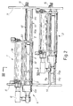
- the press comprises four printing assemblies 1, 3, 5, 7 applied to a structure 9 that comprises two side frames 11, which are rigidly connected together by a first set of tubular cross members 13 (Fig. 1) internally connected by flanges to the side frames, and by a second set of cross members 14 in the form of plates having a rectangular section, each of said plates being secured, by means of screws, on the edges of the side frames 11 in a position corresponding to a printing assembly.
- the frames 11 rest on the floor on a pair of metal guides 15, 17 with development orthogonal to the frames 11 by means of corresponding idler rollers 19, 21, each of which has a horizontal axis of rotation lying in a vertical plane parallel to the frame.
- the roller 21 has a constant diameter and rests on a plane guide 17, whereas the roller 19 has a central part of reduced diameter with end flanges designed to withhold the press in a direction orthogonal to the guides, the central part of the roller resting on one part in relief of the guide 15.
- the printing press can be easily translated sideways in spite of its considerable weight, in order to print a laminar substrate 23 coming out of any one of a series of extruders.
- the dashed line in Fig. 1 indicates a possible path of the printing substrate 23 traversed by the said substrate 23 in the direction indicated by the arrows F1, in such a way as to pass in succession, by means of return idlers 24, 25, 27, 29, 31, 33, 35, 37, 39, partially winding on four printing counter-rollers 41, 43, 45, 47, each of which co-operates with a respective printing assembly 1, 3, 5, 7 for printing the substrate 23 itself.
- the substrate 23 is kept tensioned lengthwise by the weight of a mobile roller 27, which oscillates about an axis X-X and can be partially balanced by means of a counterweight 27A.
- the printing counter-rollers 41, 43, 45, 47 are made to turn all at the same speed by a drive pulley 49A of a motor-reducer assembly 49 provided with encoder, by means of a drive belt drive 51, pulleys 41A, 43A, 45A, 47A fixed integrally with the corresponding counter-rollers, and return idlers 53, 55, 57, 59, 61 of the belt 51.
- the encoder associated to the motor reducer 49 detects the speed of rotation of the pulley 49A and, together with said speed, the rate of feed of the substrate 23 to be printed, which, since it is tensioned, adheres to the counter-rollers 41-47 without any mutual sliding.
- the four printing assemblies 1, 3, 5, 7 are basically made in the same way; consequently, in the remaining part of the description, reference will be prevalently made to just one of said assemblies, namely the assembly 1.
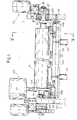
- Each printing assembly has a pair of sides 2 (Fig. 2) set at a distance apart from one another by an amount substantially smaller than the distance between the frames 11 of the press.
- the sides 2 are rigidly connected together by a cross plate 4 (see Fig. 3), to which there are applied, by means of screws, top runners 4A and bottom runners 4B of the ballscrew-recirculation type, designed to co-operate with respective guides 14A, 14B fixed at the front to each cross member 14 for supporting the printing assembly and for enabling free horizontal translation along the front of the printing press.
- an angular-displacement detector such as a potentiometer or an encoder
- Each printing assembly further comprises a pair of cylinders 1A, 1B with parallel axes, the former cylinder being a plate cylinder, and the latter cylinder being the inking cylinder, which turn on rolling bearings applied to the sides 2, and an assembly 6 for blowing hot air onto the substrate 23 which comes out of the printing assembly, so as to dry the ink that has just been applied.
- the plate cylinder 1A is motor driven by means of a variable-speed motor 8 (Fig. 2) equipped with encoder.
- the inking cylinder 1B is driven in rotation by the plate cylinder 1A by means of a belt drive 1C (Fig. 1).
- the drive is set adjacent to one side 2 of the printing assembly and has a transmission ratio such that the peripheral speeds of the cylinders 1A, 1B are equal to one another.
- the blower assembly 6 which is set on the left-hand side of the printing assembly (as viewed in Fig. 2), comprises a centrifugal fan 6A, an electrical-resistance heat exchanger 6B designed to heat the air blown by the fan 6A, and a duct 6C (see also Fig. 3).
- the latter develops between the sides 2 of the printing assembly and has a lateral extension 6D which develops throughout the width of the printing assembly.
- Said lateral extension 6D of the duct 6C is inserted through an opening 4C made in the plate 4 of the printing assembly and through an opening 14C made in the cross member 14 of the press, in order to present to the printing substrate 23 a lateral outlet for air flow, which is protected by a wire gauze or screen 6E.
- the opening 4C and the outlet protected by the wire gauze 6E extend laterally approximately as much as the distance between the sides 2 of the printing assembly, whilst the opening 14C extends approximately as much as the distance between the frames 11 of the press.
- the blower assembly 6 enables fast drying of the print performed by the corresponding printing assembly whatever the position occupied by the printing assembly in the width of the press.
- the blower assembly may also be of the double-chamber type, with recovery of the blown air (this being well known in the art), or else it may be substituted by, or integrated with, a lamp that irradiates heat on the substrate that has just been printed.
- the inking cylinder 1B is supported by the sides 2 (Fig. 4) of the corresponding printing assembly by means of rolling bearings 93.
- a sleeve 95 Set between each of said bearings 93 and the corresponding side 2 is a sleeve 95, which is eccentric with respect to the axis of the cylinder 1B and which in turn is integral with a helical gear 97 that is coaxial to the cylinder 1B.
- Fixed to each side 91 of the printing assembly is a motor-reducer assembly 1D equipped with an encoder or other angular-rotation detector. Fitted to the output shaft of the motor reducer 1D is a wormscrew 99 (see also Fig.
- the printing counter-rollers 41-47 (Fig. 1), unlike the cylinders 1A, 1B of the printing assemblies, extend from one frame 14 to the other of press. Said counter-rollers are applied to the frames 11 by means of rolling bearings and corresponding eccentric sleeves similar to the ones 95 (Fig. 4) described for the inking cylinder 1B, and a motor reducer 41B (Fig. 1) with wormscrew which meshes with a gear wheel that is integral with the eccentric sleeve enables the counter-roller to be moved away from the corresponding plate cylinder 1A or enables the contact pressure between the counter-roller and the plate cylinder 1A to be adjusted.
- the distance between the inking cylinder 1B plus counter-roller 41-47 and the plate cylinder 1A and adjustment of the mutual pressure between them can, for all the printing assemblies, be performed by a central control unit of the printing press by means of commands issued by an operator or by a work program.
- Each printing assembly is moreover equipped with an inking device for applying ink to the inking cylinder 1B (see Figs. 4 and 5), which comprises a tray 101, an ink reservoir 102, and a pipe 104 which connects the reservoir to the tray.
- the latter is fixed to a first cross member 103 which can be raised above a second cross member 105 by means of a pair of jack screws 107 fixed to said cross member 105.
- the assembly made up of the tray 101, the cross members 103, 105, and the jack screws 107 is suspended at the ends of the cylinder 1B by means of a pair of brackets 109 with interposition of corresponding rolling bearings 111.
- Pins 112 projecting from the sides 2 of the printing assembly and inserted in vertical slots 109A of the brackets 109 prevent the brackets and the tray from oscillating about the axis of the cylinder 1B.
- the slots 109A extend in the direction of the axis of the inking cylinder 1B, and their extension is such that they enable displacements of the latter obtained by rotation of the eccentric sleeves 95.
- the tray 101 can be kept lowered with the bottom surface of the cross member 103 in the vicinity of the top surface of the cross member 105 (in this position, the level of the ink contained in the tray 101 does not touch the peripheral surface of the inking cylinder), or else it may be lifted and brought to bear upon adjustable contrast surfaces 113.
- the cylinder 1B is partially immersed in the tray, as illustrated in particular in Fig. 5, and two doctor knives or blades 115, which extend throughout the length of the cylinder 1B and are applied by means of screws to the edges of the tray 101, come into contact with the cylinder 1B to remove, by rotation of the cylinder itself, any excess ink therefrom.
- the ink in the tray 101 reaches and maintains a level that grazes the uppermost part of the supply outlet 101A of the ink.
- the ink reservoir 102 is closed in an air-tight way by means of a lid 102A and has a manual air valve (not shown in the drawing) which is normally kept closed, so that the only possibility of air entering the reservoir is through the aforesaid outlet 101A and the pipe 104.
- the reservoir 102 is suspended at a level higher than that of the tray 101 by means of a hook 117 fixed to the side of the printing assembly.
- the pipe 104 is a flexible one and, in the event of maintenance operations on the press or in the event of a printing-colour change, enables the reservoir 102 to be detached from the hook 117 and to be brought, thanks to the flexibility of the pipe 104, to a level lower than the level of the tray. In this way, the ink contained in the tray 101 can be made to re-enter the reservoir 102 completely, without any risk of spilling.
- the inking system described above is particularly suited for small of medium printing volumes.
- For high printing volumes it is possible to use more complex, already known systems for supplying ink to the tray by means of a pump.
- a plate 119 (Fig. 6) which extends through an angle ⁇ of less than 360°, or else two plates 121 (Fig. 7), each of which extends through an angle ⁇ of less than 180° and which are staggered with respect to one another by 180°.
- a plate 123 (Fig. 8) which extends as far as the periphery of the plate cylinder 1A itself.
- the plate cylinders of the four printing assemblies can therefore be equipped with plates according to any one of the ways described above, irrespective of one another.
- Fig. 10 shows a printing substrate 23 that develops in a continuous strip according to the direction F4, on which, using the press described herein, various printing patterns can be printed in combination:
- the encoder and the corresponding variable-speed motor 8 associated to each assembly which is made up of the plate cylinder 1A and of the inking cylinder 1B, the encoder coupled to the motor reducer 49, which detects the speed of the substrate 23 that is to be printed, and a control unit (not illustrated in the drawing) for driving rotation of said motors 8, 49, which is designed to receive the signals emitted by said encoders and to adjust individually said motors, enable, during printing contact, the peripheral speed of the plates mounted on the various plate cylinders to be made equal to the rate of advance of the substrate, and, in the case of the printing assemblies 3, 5, 7, while the plates are not in contact with the printing substrate, enable the speed of the plate cylinders 1A to vary with respect to the linear speed of the substrate 23 that is to be printed, which is maintained constant, thus obtaining the pre-set printing pitches of the various printing patterns.
Landscapes
- Engineering & Computer Science (AREA)
- Mechanical Engineering (AREA)
- Inking, Control Or Cleaning Of Printing Machines (AREA)
- Rotary Presses (AREA)
- Advancing Webs (AREA)
- Paper (AREA)
- Color Printing (AREA)
Abstract
Description
- The present invention relates to a printing press provided with a multiplicity of printing assemblies, for example four or more, each assembly comprising a plate-carrying cylinder to which is applied at least one printing plate, and an inking cylinder. The printing press may be of the central-drum type or even of the type with independent cylinders, the so-called "stack", i.e., of the type in which each printing assembly is provided with its own counter-roller about which the printing substrate passes.
- The object of the present invention is to bestow on said printing presses a greater versatility, in particular for printing substrates of considerable width, for example 2600 mm, like the ones made of plastic film designed for forming protective wrappings for mattresses or other voluminous articles. In such cases, the possibility is required of printing said substrates in longitudinal bands of different widths, with different pitches and/or colours.
- In a printing press according to the invention, at least one of the printing assemblies has the plate cylinder and the inking cylinder with a width substantially smaller than that of the printing counter-roller, and said at least one printing assembly may be located in any position along the axis of the printing counter-roller by individual means for lateral displacement. The length of the plate cylinders and of the inking cylinders of said at least one printing assembly may also be approximately a submultiple of the length of the corresponding printing counter-roller.
- In a preferred embodiment of the invention, for each printing assembly there are provided means for synchronization between the rotation of the plate cylinder and the inking cylinder on the one hand, and the rate of advance of the substrate that is to be printed on the other. A printing plate having a length smaller than or equal to that of the circular development of the plate cylinder may be applied to the cylinder. Alternatively, there may be applied simultaneously to said plate cylinder two plates set one behind the other according to the peripheral development of the cylinder. With the above arrangement, by cyclically stopping for a pre-set time, or anyway varying periodically the speed of rotation of the various plate cylinders while their plates are not in contact with the substrate that is to be printed, it is possible to print longitudinal bands of the substrate with one or more printed patterns, repeated or alternated with pitches that are altogether independent from one band to another. Conveniently, where possible, and especially for printing pitches that are relatively long, the plate cylinder is cyclically stopped with the plate immediately upstream of the inking cylinder so that the next print will be carried out with fresh ink; i.e., inking of the plate takes place immediately before printing.
- There is thus made available, for printing on the same substrate in a single pass, a considerable number of printing combinations, for bands set alongside one another, or else completely or partially overlapping one another, of repeated printing patterns, which may possibly be alternated, even with a number of colours. In addition, the reduced length of the plate cylinder and of the inking cylinder means that they have a smaller inertia, which is a fact that enables greater precision of control of rotation of the cylinders, and hence also a better printing quality.
- In a preferred embodiment of the invention, the means for lateral displacement of each printing assembly comprise a motor reducer provided with an encoder actuating a screw that works in conjunction with a nut screw, said screw being rotatably supported on one side by a side frame of the press, and the nut screw being fixed to one side of the printing assembly. The encoder is connected to a central control unit by means of which pre-set displacements are obtained with detection of the position reached by the printing assembly along the axis of the corresponding counter-roller.
- The aforesaid means of synchronization between the plate cylinder and the inking cylinder on the one hand, and the advance of the printing substrate on the other may include: an encoder and a variable-speed motor coupled to each assembly that is made up of a plate cylinder and an inking cylinder; a variable-speed motor equipped with an encoder designed to rotate , via a transmission, the printing counter-rollers and to cause there through the advancement of the substrate that is to be printed; and means for driving rotation of said motors designed to receive the signals emitted by said encoders and to adjust individually the speed of the assembly made up of the plate cylinder and the inking cylinder according to the rate of feed of the substrate to be printed and the printing pitch required, as will be described in greater detail in what follows.
- In addition, by locating a photo-electric cell ― designed to detect passage of a pre-printed reference mark on the substrate ― along the path of the substrate and in a position corresponding to a printing assembly, it is possible to add, on a pre-printed substrate, further printing patterns positioned with sufficient precision with respect to said reference mark. In this way, with the press according to the invention it is possible, for example, to replace bar codes or other markings already printed on the substrate that are outdated with other more up-to-date ones.
- In printing presses, for each printing assembly it must be possible to adjust the pressure between the counter-roller and the plate cylinder, and the pressure between the inking cylinder and the plate cylinder, and this is normally achieved by means of eccentric sleeves for supporting the rolling bearings of the counter-roller and inking cylinder. In general, prior to start of printing, said eccentric sleeves may be rotated manually to move the counter-roller and the inking cylinder up to or away from the plate cylinder. The above operation, especially in printing presses with a lot of printing assemblies, is a long and laborious one. In a preferred embodiment of the invention, each of said eccentric sleeves is integral with the wheel of a corresponding wheel-and-wormscrew device, the screw of which can be driven by means of a respective motor reducer equipped with an angular-rotation detector ― such as a potentiometer or an encoder ― connected to an electronic control unit of the motor reducer. In this way, it is possible, via programming, to bring together said counter-roller and said inking roller with the plate cylinder, and to vary the contact pressure between them.
- The inking cylinder of each printing assembly is normally supplied with ink by means of a tray set underneath the inking cylinder and partially filled with ink, said cylinder being partially immersed in the ink. According to the invention, the level of ink in the tray is kept constant by connecting thereto a sealed ink reservoir which communicates with the atmosphere only by means of an outlet of a pipe connecting the reservoir to the tray, for flow of ink into the tray. The level of ink in the tray can be varied by displacing said outlet vertically by means of an eccentric cam, and the connecting pipe is preferably at least in part flexible in order to enable displacement of the ink reservoir to a position below the level of the tray, so as to enable emptying of the residual ink without any risk of spilling, for instance in order to carry out change of colour of the ink or during press maintenance operations.
- Preferably, the tray for inking the inking cylinder is suspended from the latter by means of rotating bearings that are coaxial with the cylinder itself, and set between the tray and said bearings is a pneumatically driven mechanism for bringing the tray up to the cylinder, or else for moving the tray away from the inking cylinder in a radial direction at the end of printing. In this way, the displacements of the inking cylinder to bring it up to the plate cylinder and to vary the pressure between the above two cylinders do not affect the position of the tray with respect to the inking cylinder, and hence the degree of inking of the inking cylinder, in so far as, in its lateral movement the inking cylinder draws along with it also the tray. In addition, by means of said pneumatically driven mechanism, inking can be interrupted or activated according to a program.
- The press according to the invention is particularly suited for printing a substrate made of plastic film coming out of an extruder or other delivery device. In particular, it can be equipped with supporting rollers to facilitate its displacement along guides set in the floor so that it can pass from one extruder to another of a battery of extruders.
- A better understanding of the present invention will be obtained from the ensuing description and from the attached drawing, which illustrates a non-limiting example of embodiment of the invention. In the drawing
- Fig. 1 is a schematic side view of a printing press according to the invention;
- Fig. 2 is a partial front view according to the line II-II of the press in Fig. 1;
- Fig. 3 is an enlarged partial side view of a printing assembly of the press, according to the cross section taken along the line III-III of Fig. 2;
- Fig. 4 is an enlarged partial view of a detail of the press, taken along the line IV-IV of Fig. 1;
- Fig. 5 is a view according to the cross section taken along the line V-V of Fig. 4;
- Figs. 6, 7 and 8 show diagrams of use of plates in a printing assembly; and
- Fig. 9 is a schematic illustration of a printing configuration obtained with the press according to the invention.
-
- The printing press which will be described in what follows is particularly designed for printing a plastic laminar substrate obtained by extrusion and suitable for packaging of various articles, also including voluminous ones, such as mattresses. With reference to Figs 1 and 2, the press comprises four
printing assemblies side frames 11, which are rigidly connected together by a first set of tubular cross members 13 (Fig. 1) internally connected by flanges to the side frames, and by a second set ofcross members 14 in the form of plates having a rectangular section, each of said plates being secured, by means of screws, on the edges of theside frames 11 in a position corresponding to a printing assembly. Theframes 11 rest on the floor on a pair ofmetal guides frames 11 by means ofcorresponding idler rollers 19, 21, each of which has a horizontal axis of rotation lying in a vertical plane parallel to the frame. Theroller 21 has a constant diameter and rests on aplane guide 17, whereas the roller 19 has a central part of reduced diameter with end flanges designed to withhold the press in a direction orthogonal to the guides, the central part of the roller resting on one part in relief of theguide 15. In this way, the printing press can be easily translated sideways in spite of its considerable weight, in order to print alaminar substrate 23 coming out of any one of a series of extruders. - The dashed line in Fig. 1 indicates a possible path of the
printing substrate 23 traversed by the saidsubstrate 23 in the direction indicated by the arrows F1, in such a way as to pass in succession, by means ofreturn idlers printing counter-rollers respective printing assembly substrate 23 itself. Thesubstrate 23 is kept tensioned lengthwise by the weight of amobile roller 27, which oscillates about an axis X-X and can be partially balanced by means of acounterweight 27A. Theprinting counter-rollers drive pulley 49A of a motor-reducer assembly 49 provided with encoder, by means of adrive belt drive 51,pulleys 41A, 43A, 45A, 47A fixed integrally with the corresponding counter-rollers, andreturn idlers belt 51. The encoder associated to the motor reducer 49 detects the speed of rotation of thepulley 49A and, together with said speed, the rate of feed of thesubstrate 23 to be printed, which, since it is tensioned, adheres to the counter-rollers 41-47 without any mutual sliding. - The four
printing assemblies frames 11 of the press. Thesides 2 are rigidly connected together by a cross plate 4 (see Fig. 3), to which there are applied, by means of screws,top runners 4A andbottom runners 4B of the ballscrew-recirculation type, designed to co-operate withrespective guides cross member 14 for supporting the printing assembly and for enabling free horizontal translation along the front of the printing press. Amotor reducer 16 equipped with an angular-displacement detector, such as a potentiometer or an encoder, is applied to the right-hand frame of the printing press (as viewed in Fig. 2) and causes awormscrew 18 to turn inside anut screw 20 fixed to the right-hand side 2 of the printing assembly. In this way, when themotor reducer 16 is driven in a controlled way, it is possible to position each printing assembly in the desired printing position along the width of the press. - Each printing assembly further comprises a pair of
cylinders sides 2, and anassembly 6 for blowing hot air onto thesubstrate 23 which comes out of the printing assembly, so as to dry the ink that has just been applied. Theplate cylinder 1A is motor driven by means of a variable-speed motor 8 (Fig. 2) equipped with encoder. The inkingcylinder 1B is driven in rotation by theplate cylinder 1A by means of abelt drive 1C (Fig. 1). The drive is set adjacent to oneside 2 of the printing assembly and has a transmission ratio such that the peripheral speeds of thecylinders - The
blower assembly 6, which is set on the left-hand side of the printing assembly (as viewed in Fig. 2), comprises a centrifugal fan 6A, an electrical-resistance heat exchanger 6B designed to heat the air blown by the fan 6A, and aduct 6C (see also Fig. 3). The latter develops between thesides 2 of the printing assembly and has alateral extension 6D which develops throughout the width of the printing assembly. Saidlateral extension 6D of theduct 6C is inserted through an opening 4C made in theplate 4 of the printing assembly and through an opening 14C made in thecross member 14 of the press, in order to present to the printing substrate 23 a lateral outlet for air flow, which is protected by a wire gauze orscreen 6E. The opening 4C and the outlet protected by thewire gauze 6E extend laterally approximately as much as the distance between thesides 2 of the printing assembly, whilst the opening 14C extends approximately as much as the distance between theframes 11 of the press. In this way, theblower assembly 6 enables fast drying of the print performed by the corresponding printing assembly whatever the position occupied by the printing assembly in the width of the press. The blower assembly may also be of the double-chamber type, with recovery of the blown air (this being well known in the art), or else it may be substituted by, or integrated with, a lamp that irradiates heat on the substrate that has just been printed. - The inking
cylinder 1B is supported by the sides 2 (Fig. 4) of the corresponding printing assembly by means ofrolling bearings 93. Set between each of saidbearings 93 and thecorresponding side 2 is asleeve 95, which is eccentric with respect to the axis of thecylinder 1B and which in turn is integral with ahelical gear 97 that is coaxial to thecylinder 1B. Fixed to each side 91 of the printing assembly is a motor-reducer assembly 1D equipped with an encoder or other angular-rotation detector. Fitted to the output shaft of themotor reducer 1D is a wormscrew 99 (see also Fig. 1) which meshes with saidhelical gear 97 to enable rotation of saideccentric sleeve 95 by a convenient angle such as to enable theinking cylinder 1B to be brought up to theplate cylinder 1A so as to exert a pre-set pressure on the latter, or to enable theinking cylinder 1B and theplate cylinder 1A to be moved away from one another. - The printing counter-rollers 41-47 (Fig. 1), unlike the
cylinders frame 14 to the other of press. Said counter-rollers are applied to theframes 11 by means of rolling bearings and corresponding eccentric sleeves similar to the ones 95 (Fig. 4) described for theinking cylinder 1B, and amotor reducer 41B (Fig. 1) with wormscrew which meshes with a gear wheel that is integral with the eccentric sleeve enables the counter-roller to be moved away from thecorresponding plate cylinder 1A or enables the contact pressure between the counter-roller and theplate cylinder 1A to be adjusted. - In this way, the distance between the inking
cylinder 1B plus counter-roller 41-47 and theplate cylinder 1A and adjustment of the mutual pressure between them can, for all the printing assemblies, be performed by a central control unit of the printing press by means of commands issued by an operator or by a work program. - Each printing assembly is moreover equipped with an inking device for applying ink to the
inking cylinder 1B (see Figs. 4 and 5), which comprises atray 101, anink reservoir 102, and apipe 104 which connects the reservoir to the tray. The latter is fixed to afirst cross member 103 which can be raised above asecond cross member 105 by means of a pair ofjack screws 107 fixed to saidcross member 105. The assembly made up of thetray 101, thecross members cylinder 1B by means of a pair ofbrackets 109 with interposition of corresponding rollingbearings 111.Pins 112 projecting from thesides 2 of the printing assembly and inserted invertical slots 109A of thebrackets 109 prevent the brackets and the tray from oscillating about the axis of thecylinder 1B. Theslots 109A extend in the direction of the axis of theinking cylinder 1B, and their extension is such that they enable displacements of the latter obtained by rotation of theeccentric sleeves 95. By means of saidjack screws 107, thetray 101 can be kept lowered with the bottom surface of thecross member 103 in the vicinity of the top surface of the cross member 105 (in this position, the level of the ink contained in thetray 101 does not touch the peripheral surface of the inking cylinder), or else it may be lifted and brought to bear upon adjustable contrast surfaces 113. With this latter arrangement, thecylinder 1B is partially immersed in the tray, as illustrated in particular in Fig. 5, and two doctor knives orblades 115, which extend throughout the length of thecylinder 1B and are applied by means of screws to the edges of thetray 101, come into contact with thecylinder 1B to remove, by rotation of the cylinder itself, any excess ink therefrom. - Thanks to the continuous supply of ink from the
reservoir 102, the ink in thetray 101 reaches and maintains a level that grazes the uppermost part of thesupply outlet 101A of the ink. In fact, theink reservoir 102 is closed in an air-tight way by means of alid 102A and has a manual air valve (not shown in the drawing) which is normally kept closed, so that the only possibility of air entering the reservoir is through theaforesaid outlet 101A and thepipe 104. During printing, thereservoir 102 is suspended at a level higher than that of thetray 101 by means of ahook 117 fixed to the side of the printing assembly. Thepipe 104 is a flexible one and, in the event of maintenance operations on the press or in the event of a printing-colour change, enables thereservoir 102 to be detached from thehook 117 and to be brought, thanks to the flexibility of thepipe 104, to a level lower than the level of the tray. In this way, the ink contained in thetray 101 can be made to re-enter thereservoir 102 completely, without any risk of spilling. - The inking system described above is particularly suited for small of medium printing volumes. For high printing volumes, it is possible to use more complex, already known systems for supplying ink to the tray by means of a pump.
- There may be applied to the
plate cylinder 1A a plate 119 (Fig. 6) which extends through an angle α of less than 360°, or else two plates 121 (Fig. 7), each of which extends through an angle β of less than 180° and which are staggered with respect to one another by 180°. Yet again, it is possible to apply to theplate cylinder 1A a plate 123 (Fig. 8) which extends as far as the periphery of theplate cylinder 1A itself. The plate cylinders of the four printing assemblies can therefore be equipped with plates according to any one of the ways described above, irrespective of one another. In addition, by appropriate lateral staggering of theindividual printing assemblies plate cylinder 1A during each revolution thereof, it is possible to obtain printing pitches that differ from one band to another band of the substrate. For example, Fig. 10 shows aprinting substrate 23 that develops in a continuous strip according to the direction F4, on which, using the press described herein, various printing patterns can be printed in combination: - by means of the printing assembly 1, a
band 23A with the pattern "MAFLEX" (or other full background) repeated continuously with a constant pitch (pa), with a plate of the type designated by 123 applied as illustrated in Fig. 8; - by means of the
printing assembly 3, a band 23B with twopatterns band 23A, with two plates of the type designated by 121 applied as illustrated in Fig. 7. In this case, the speed of theplate cylinder 1A is varied by cyclically decelerating its rotation as soon as one of the two plates interrupts contact with the printing substrate, and then re-accelerating it to make its speed the same as the rate of advance of theprinting substrate 23 before the other plate comes into contact with theprinting substrate 23; - by means of the
printing assemblies respective bands - With the above arrangement, in the case of the print of Fig. 10, the encoder and the corresponding variable-speed motor 8 associated to each assembly, which is made up of the
plate cylinder 1A and of theinking cylinder 1B, the encoder coupled to themotor reducer 49, which detects the speed of thesubstrate 23 that is to be printed, and a control unit (not illustrated in the drawing) for driving rotation of saidmotors 8, 49, which is designed to receive the signals emitted by said encoders and to adjust individually said motors, enable, during printing contact, the peripheral speed of the plates mounted on the various plate cylinders to be made equal to the rate of advance of the substrate, and, in the case of theprinting assemblies plate cylinders 1A to vary with respect to the linear speed of thesubstrate 23 that is to be printed, which is maintained constant, thus obtaining the pre-set printing pitches of the various printing patterns. - It is understood that the drawing only illustrates a possible exemplification of the invention given purely to provide a practical demonstration of the said invention, which may vary in its embodiments and arrangements without thereby departing from the scope of the underlying idea. The possible presence of reference numbers in the attached claims has the purpose of facilitating reading thereof in the light of the foregoing description and in no way limits the scope of protection represented by the claims.
Claims (15)
- A printing press comprising: a multiplicity of printing assemblies, each of which is provided with a plate cylinder ― to which at least one printing plate can be applied ― and an inking cylinder; one or more printing counter-rollers on which a substrate to be printed is guided; characterized in that at least one of said printing assemblies (1, 3, 5, 7) has the plate cylinder (1A) and the inking cylinder (1B) that have a length substantially smaller than that of the printing counter-roller (41, 43, 45, 47), and in that said at least one printing assembly (1, 3, 5, 7) may be located in any position along the axis of said respective printing counter-roller (41, 43, 45, 47) by individual lateral-displacement means (16, 18), to enable printing of corresponding longitudinal bands set alongside one another, or else completely or partially overlapping one another, of the printing substrate.
- The printing press according to Claim 1, characterized in that it comprises individual means of synchronization (8, 49) between rotation of the plate cylinder (1A) and the inking cylinder (1B) of at least one printing assembly on the one hand, and advance of the printing substrate (23) on the other, said means being designed to enable pre-set cyclic variations in the speed of rotation of the plate cylinder (1A)-inking cylinder (1B) assemblies of the printing assembly with respect to the rate of feed of the substrate when the plate is not in contact with it, so as to vary the printing pitch as desired.
- The press according to Claim 1 or 2, characterized in that the length of the plate cylinders (1A) and of the inking cylinders (1B) of said at least one printing assembly is approximately a submultiple of the length of the corresponding printing counter-roller (41, 43, 45, 47).
- The press according to Claim 1 or 2, characterized in that said means for lateral displacement of each printing assembly comprise a motor reducer (16) provided with an encoder and designed to translate in the direction of the printing width, transversely with respect to the press, the corresponding printing assembly by means of a wormscrew (18) and a nut screw (20) associated thereto.
- The press according to any one of the foregoing claims, characterized in that said synchronization means comprise an encoder and a variable-speed motor (8) associated to each printing assembly made up of a plate cylinder (1A) and an inking cylinder (1B), an encoder coupled to a motor reducer (49) for feeding the substrate (23) that is to be printed, and means for driving rotation of said motors (8, 49), which are designed to receive the signals emitted by said encoders and to adjust individually the speed of the assembly made up of the plate cylinder (1A) and inking cylinder (1B), according to the rate of feed of the substrate (23) to be printed.
- The press according to Claim 5, characterized in that it comprises, in each position corresponding to each of said printing assemblies, a photoelectric cell designed to detect passage of a reference mark pre-printed on the printing substrate and to activate accordingly operation of the corresponding printing assembly in order to add, on the substrate, further printing patterns positioned in relation to said reference mark.
- The press according to any one of the foregoing claims, characterized in that there may be applied, to said plate cylinder (1A), a plate (119, 121, 123) having a length smaller than or equal to the length of the circular development of the cylinder (1A) itself.
- The press according to any one of Claims 1 to 4, characterized in that there may be applied at the same time to said plate cylinder (1A) two plates (121) set one after the other according to the peripheral development of the cylinder, with a pitch of 180°.
- The press according to any one of the foregoing claims, in which the inking cylinder (1B) of each printing assembly is supplied with ink by means of a corresponding tray (101) partially filled with ink, in which the inking cylinder (1B) is partially immersed, characterized in that the ink in the tray (101) is kept at a constant level by means of a sealed reservoir (102) for supplying ink, which communicates with the atmosphere only by means of the outlet (101A) of a pipe (104) connecting the reservoir to the tray, for flow of ink into the tray.
- The press according to Claim 9, characterized in that the level of ink in the tray (101) may be varied by displacing said outlet vertically with respect to the tray by means of an eccentric cam.
- The press according to Claim 9 or Claim 10, characterized in that said connecting pipe (104) is at least in part flexible to enable displacement of the ink reservoir (102) below the tray (101) so as to empty the residual ink from the tray without any risk of spilling, for example in the event of a colour change or for press maintenance operations.
- The press according to any one of Claims 8 to 11, characterized in that the tray (101) for inking the inking cylinder is suspended from the latter by rotation bearings (111), and in that set between the tray and said bearings (111) is a pneumatically driven mechanism (107) for bringing the tray (101) up to the inking cylinder (1B), or else for moving the tray (101) away from the inking cylinder (1B) in a radial direction.
- The press according to any one of the foregoing claims, in which for each printing assembly (1, 3, 5, 7) the pressure between the counter-roller (41, 43, 45, 47) and the plate cylinder (1A) and the pressure between the inking cylinder (1B) and the plate cylinder (1A) may be adjusted by means of eccentric sleeves (95) for supporting the bearings (93) of the inking cylinder (1B) and the counter-roller (41, 43, 45, 47), characterized in that each of said eccentric sleeves (95) is integral with the wheel (97) of a wheel-and-wormscrew device, the screw (99) of which can be driven by means of a corresponding motor reducer (1D) equipped with an angular-rotation detector ― such as a potentiometer or an encoder ― connected to an electronic control unit of said motor reducer so that it is possible, via remote control, to bring together said counter-roller (41, 43, 45, 47) and said inking roller (1B) with the plate cylinder (1A), and to vary the contact pressure between them.
- The press according to any one of the foregoing claims, and arranged for printing a substrate made of plastic film coming out of an extruder, characterized in that it is equipped with supporting rollers (21) designed to roll along parallel guides (15, 17) to facilitate displacement of said press in front of a device for delivering a substrate to be printed, such as an extruder, a reel or some other delivery means, or a battery of such delivery means.
- A printing press provided with a multiplicity of printing assemblies for the simultaneous printing of longitudinal bands, also but not necessarily overlapping one another, of a printing substrate; the foregoing as described above and as represented by way of example in the attached plate of drawings.
Priority Applications (4)
| Application Number | Priority Date | Filing Date | Title |
|---|---|---|---|
| EP01830473A EP1277574B1 (en) | 2001-07-17 | 2001-07-17 | Multicolour web printing press |
| DE60118900T DE60118900T2 (en) | 2001-07-17 | 2001-07-17 | Multicolor web press |
| ES01830473T ES2261370T3 (en) | 2001-07-17 | 2001-07-17 | MULTICOLOR PRINT PRESS OF LONGITUDINAL BANDS. |
| AT01830473T ATE323603T1 (en) | 2001-07-17 | 2001-07-17 | MULTI COLOR ROLL PRINTING MACHINE |
Applications Claiming Priority (1)
| Application Number | Priority Date | Filing Date | Title |
|---|---|---|---|
| EP01830473A EP1277574B1 (en) | 2001-07-17 | 2001-07-17 | Multicolour web printing press |
Publications (2)
| Publication Number | Publication Date |
|---|---|
| EP1277574A1 true EP1277574A1 (en) | 2003-01-22 |
| EP1277574B1 EP1277574B1 (en) | 2006-04-19 |
Family
ID=8184618
Family Applications (1)
| Application Number | Title | Priority Date | Filing Date |
|---|---|---|---|
| EP01830473A Expired - Lifetime EP1277574B1 (en) | 2001-07-17 | 2001-07-17 | Multicolour web printing press |
Country Status (4)
| Country | Link |
|---|---|
| EP (1) | EP1277574B1 (en) |
| AT (1) | ATE323603T1 (en) |
| DE (1) | DE60118900T2 (en) |
| ES (1) | ES2261370T3 (en) |
Cited By (2)
| Publication number | Priority date | Publication date | Assignee | Title |
|---|---|---|---|---|
| EP1728629A2 (en) | 2005-05-31 | 2006-12-06 | Maflex S.r.l. | Printing machine with variable width, method to vary the printing width and method for lateral movement of the machine |
| WO2017172683A3 (en) * | 2016-03-30 | 2017-11-09 | Apex Brands, Inc. | Printing assembly and method for printing on a flexible substrate |
Families Citing this family (1)
| Publication number | Priority date | Publication date | Assignee | Title |
|---|---|---|---|---|
| US20190322123A1 (en) * | 2017-01-01 | 2019-10-24 | Advanced Environmental Recycling Technologies, Inc. | Methods for coating composite articles |
Citations (7)
| Publication number | Priority date | Publication date | Assignee | Title |
|---|---|---|---|---|
| DE24523C (en) * | KOENIG & BAUER in Kloster Oberzell bei Würzburg | Double rotary press for two-color printing, table and illustration printing | ||
| DE532024C (en) * | 1931-08-20 | Fallert & Co Akt Ges | Rotary printing press | |
| US1867314A (en) * | 1931-06-04 | 1932-07-12 | Transparent Packaging & Printi | Method for multicolor printing on transparent cellulose paper and product resulting from the same |
| US2836115A (en) * | 1955-05-24 | 1958-05-27 | Donald J Page | Rotary web aniline press |
| EP0213578A2 (en) * | 1985-08-31 | 1987-03-11 | Werner Kammann Maschinenfabrik GmbH. | Multi-colour rotary printing press |
| EP0226554A1 (en) * | 1985-12-19 | 1987-06-24 | GRAPHIC MACHINE SERVICE S.r.l. | A flexographic machine |
| US5692442A (en) * | 1997-03-05 | 1997-12-02 | Interflex Llc. | Web printing apparatus |
-
2001
- 2001-07-17 EP EP01830473A patent/EP1277574B1/en not_active Expired - Lifetime
- 2001-07-17 DE DE60118900T patent/DE60118900T2/en not_active Expired - Lifetime
- 2001-07-17 ES ES01830473T patent/ES2261370T3/en not_active Expired - Lifetime
- 2001-07-17 AT AT01830473T patent/ATE323603T1/en not_active IP Right Cessation
Patent Citations (7)
| Publication number | Priority date | Publication date | Assignee | Title |
|---|---|---|---|---|
| DE24523C (en) * | KOENIG & BAUER in Kloster Oberzell bei Würzburg | Double rotary press for two-color printing, table and illustration printing | ||
| DE532024C (en) * | 1931-08-20 | Fallert & Co Akt Ges | Rotary printing press | |
| US1867314A (en) * | 1931-06-04 | 1932-07-12 | Transparent Packaging & Printi | Method for multicolor printing on transparent cellulose paper and product resulting from the same |
| US2836115A (en) * | 1955-05-24 | 1958-05-27 | Donald J Page | Rotary web aniline press |
| EP0213578A2 (en) * | 1985-08-31 | 1987-03-11 | Werner Kammann Maschinenfabrik GmbH. | Multi-colour rotary printing press |
| EP0226554A1 (en) * | 1985-12-19 | 1987-06-24 | GRAPHIC MACHINE SERVICE S.r.l. | A flexographic machine |
| US5692442A (en) * | 1997-03-05 | 1997-12-02 | Interflex Llc. | Web printing apparatus |
Cited By (5)
| Publication number | Priority date | Publication date | Assignee | Title |
|---|---|---|---|---|
| EP1728629A2 (en) | 2005-05-31 | 2006-12-06 | Maflex S.r.l. | Printing machine with variable width, method to vary the printing width and method for lateral movement of the machine |
| EP1728629A3 (en) * | 2005-05-31 | 2009-02-11 | Maflex S.r.l. | Printing machine with variable width, method to vary the printing width and method for lateral movement of the machine |
| WO2017172683A3 (en) * | 2016-03-30 | 2017-11-09 | Apex Brands, Inc. | Printing assembly and method for printing on a flexible substrate |
| US11186078B2 (en) | 2016-03-30 | 2021-11-30 | Apex Brands, Inc. | Printing assembly and method for printing on a flexible substrate |
| US11479031B2 (en) | 2016-03-30 | 2022-10-25 | Apex Brands, Inc. | Measuring tape with printing on flexible substrate |
Also Published As
| Publication number | Publication date |
|---|---|
| ES2261370T3 (en) | 2006-11-16 |
| EP1277574B1 (en) | 2006-04-19 |
| DE60118900T2 (en) | 2006-11-30 |
| DE60118900D1 (en) | 2006-05-24 |
| ATE323603T1 (en) | 2006-05-15 |
Similar Documents
| Publication | Publication Date | Title |
|---|---|---|
| US8505450B2 (en) | Printing unit, printing press and method of producing labels or self-adhesive labels in a printing press | |
| JP2004508972A (en) | Ink jet printer | |
| US4236955A (en) | Printing and die-cutting apparatus | |
| US5816994A (en) | Box-blank printer/slotting apparatus | |
| US10315444B2 (en) | Printing device | |
| EP0771623B1 (en) | Cutting device for cutting continuous webs | |
| EP1277574B1 (en) | Multicolour web printing press | |
| US4628814A (en) | Flat screen printing machine | |
| US9387667B2 (en) | Inspection system for inspecting the quality of printed sheets | |
| US4216676A (en) | Apparatus for the testing of printing or like cylinders for operating on web material | |
| CA1310992C (en) | Printing press | |
| US6557468B2 (en) | Delivery for a sheet processing machine, particularly for a sheet-fed printing machine | |
| CN216507463U (en) | UV spouts seal paging and detects all-in-one | |
| EP0781721B1 (en) | Machine for laying out laminar products | |
| GB2322850A (en) | Sheet brake | |
| KR200196441Y1 (en) | Label printer | |
| CN221343272U (en) | Gluing and slitting device | |
| CN218986084U (en) | Circulating film pressing equipment | |
| AU2016204019B2 (en) | Inspection system for inspecting the quality of printed sheets | |
| GB190418776A (en) | Improvements in Printing Presses | |
| KR200290887Y1 (en) | A laminator for printed matter | |
| CN114644249A (en) | Printing system for non-woven fabric production | |
| AU2014201957A1 (en) | Inspection system for inspecting the quality of printed sheets | |
| ITCO980020A1 (en) | FABRIC ADVANCEMENT APPARATUS FOR COLOR COLOR INK-JET PRINTERS AND / OR PLOTTERS |
Legal Events
| Date | Code | Title | Description |
|---|---|---|---|
| PUAI | Public reference made under article 153(3) epc to a published international application that has entered the european phase |
Free format text: ORIGINAL CODE: 0009012 |
|
| 17P | Request for examination filed |
Effective date: 20020330 |
|
| AK | Designated contracting states |
Kind code of ref document: A1 Designated state(s): AT BE CH CY DE DK ES FI FR GB GR IE IT LI LU MC NL PT SE TR |
|
| AX | Request for extension of the european patent |
Free format text: AL;LT;LV;MK;RO;SI |
|
| 17Q | First examination report despatched |
Effective date: 20030611 |
|
| AKX | Designation fees paid |
Designated state(s): AT BE CH CY DE DK ES FI FR GB GR IE IT LI LU MC NL PT SE TR |
|
| GRAP | Despatch of communication of intention to grant a patent |
Free format text: ORIGINAL CODE: EPIDOSNIGR1 |
|
| GRAS | Grant fee paid |
Free format text: ORIGINAL CODE: EPIDOSNIGR3 |
|
| GRAA | (expected) grant |
Free format text: ORIGINAL CODE: 0009210 |
|
| AK | Designated contracting states |
Kind code of ref document: B1 Designated state(s): AT BE CH CY DE DK ES FI FR GB GR IE IT LI LU MC NL PT SE TR |
|
| PG25 | Lapsed in a contracting state [announced via postgrant information from national office to epo] |
Ref country code: AT Free format text: LAPSE BECAUSE OF FAILURE TO SUBMIT A TRANSLATION OF THE DESCRIPTION OR TO PAY THE FEE WITHIN THE PRESCRIBED TIME-LIMIT Effective date: 20060419 Ref country code: NL Free format text: LAPSE BECAUSE OF FAILURE TO SUBMIT A TRANSLATION OF THE DESCRIPTION OR TO PAY THE FEE WITHIN THE PRESCRIBED TIME-LIMIT Effective date: 20060419 Ref country code: FI Free format text: LAPSE BECAUSE OF FAILURE TO SUBMIT A TRANSLATION OF THE DESCRIPTION OR TO PAY THE FEE WITHIN THE PRESCRIBED TIME-LIMIT Effective date: 20060419 Ref country code: CH Free format text: LAPSE BECAUSE OF FAILURE TO SUBMIT A TRANSLATION OF THE DESCRIPTION OR TO PAY THE FEE WITHIN THE PRESCRIBED TIME-LIMIT Effective date: 20060419 Ref country code: BE Free format text: LAPSE BECAUSE OF FAILURE TO SUBMIT A TRANSLATION OF THE DESCRIPTION OR TO PAY THE FEE WITHIN THE PRESCRIBED TIME-LIMIT Effective date: 20060419 Ref country code: LI Free format text: LAPSE BECAUSE OF FAILURE TO SUBMIT A TRANSLATION OF THE DESCRIPTION OR TO PAY THE FEE WITHIN THE PRESCRIBED TIME-LIMIT Effective date: 20060419 |
|
| REG | Reference to a national code |
Ref country code: GB Ref legal event code: FG4D |
|
| REF | Corresponds to: |
Ref document number: 60118900 Country of ref document: DE Date of ref document: 20060524 Kind code of ref document: P |
|
| REG | Reference to a national code |
Ref country code: IE Ref legal event code: FG4D |
|
| PG25 | Lapsed in a contracting state [announced via postgrant information from national office to epo] |
Ref country code: IE Free format text: LAPSE BECAUSE OF NON-PAYMENT OF DUE FEES Effective date: 20060717 |
|
| PG25 | Lapsed in a contracting state [announced via postgrant information from national office to epo] |
Ref country code: DK Free format text: LAPSE BECAUSE OF FAILURE TO SUBMIT A TRANSLATION OF THE DESCRIPTION OR TO PAY THE FEE WITHIN THE PRESCRIBED TIME-LIMIT Effective date: 20060719 Ref country code: SE Free format text: LAPSE BECAUSE OF FAILURE TO SUBMIT A TRANSLATION OF THE DESCRIPTION OR TO PAY THE FEE WITHIN THE PRESCRIBED TIME-LIMIT Effective date: 20060719 |
|
| PG25 | Lapsed in a contracting state [announced via postgrant information from national office to epo] |
Ref country code: MC Free format text: LAPSE BECAUSE OF NON-PAYMENT OF DUE FEES Effective date: 20060731 |
|
| PG25 | Lapsed in a contracting state [announced via postgrant information from national office to epo] |
Ref country code: PT Free format text: LAPSE BECAUSE OF FAILURE TO SUBMIT A TRANSLATION OF THE DESCRIPTION OR TO PAY THE FEE WITHIN THE PRESCRIBED TIME-LIMIT Effective date: 20060919 |
|
| NLV1 | Nl: lapsed or annulled due to failure to fulfill the requirements of art. 29p and 29m of the patents act | ||
| REG | Reference to a national code |
Ref country code: CH Ref legal event code: PL |
|
| REG | Reference to a national code |
Ref country code: ES Ref legal event code: FG2A Ref document number: 2261370 Country of ref document: ES Kind code of ref document: T3 |
|
| ET | Fr: translation filed | ||
| PLBE | No opposition filed within time limit |
Free format text: ORIGINAL CODE: 0009261 |
|
| STAA | Information on the status of an ep patent application or granted ep patent |
Free format text: STATUS: NO OPPOSITION FILED WITHIN TIME LIMIT |
|
| 26N | No opposition filed |
Effective date: 20070122 |
|
| PG25 | Lapsed in a contracting state [announced via postgrant information from national office to epo] |
Ref country code: GR Free format text: LAPSE BECAUSE OF FAILURE TO SUBMIT A TRANSLATION OF THE DESCRIPTION OR TO PAY THE FEE WITHIN THE PRESCRIBED TIME-LIMIT Effective date: 20060720 |
|
| PG25 | Lapsed in a contracting state [announced via postgrant information from national office to epo] |
Ref country code: TR Free format text: LAPSE BECAUSE OF FAILURE TO SUBMIT A TRANSLATION OF THE DESCRIPTION OR TO PAY THE FEE WITHIN THE PRESCRIBED TIME-LIMIT Effective date: 20060419 Ref country code: LU Free format text: LAPSE BECAUSE OF NON-PAYMENT OF DUE FEES Effective date: 20060717 |
|
| PG25 | Lapsed in a contracting state [announced via postgrant information from national office to epo] |
Ref country code: CY Free format text: LAPSE BECAUSE OF FAILURE TO SUBMIT A TRANSLATION OF THE DESCRIPTION OR TO PAY THE FEE WITHIN THE PRESCRIBED TIME-LIMIT Effective date: 20060419 |
|
| PGFP | Annual fee paid to national office [announced via postgrant information from national office to epo] |
Ref country code: DE Payment date: 20100927 Year of fee payment: 10 |
|
| PGFP | Annual fee paid to national office [announced via postgrant information from national office to epo] |
Ref country code: FR Payment date: 20110802 Year of fee payment: 11 |
|
| PGFP | Annual fee paid to national office [announced via postgrant information from national office to epo] |
Ref country code: GB Payment date: 20110713 Year of fee payment: 11 Ref country code: ES Payment date: 20110720 Year of fee payment: 11 |
|
| PGFP | Annual fee paid to national office [announced via postgrant information from national office to epo] |
Ref country code: IT Payment date: 20110713 Year of fee payment: 11 |
|
| GBPC | Gb: european patent ceased through non-payment of renewal fee |
Effective date: 20120717 |
|
| REG | Reference to a national code |
Ref country code: FR Ref legal event code: ST Effective date: 20130329 |
|
| PG25 | Lapsed in a contracting state [announced via postgrant information from national office to epo] |
Ref country code: GB Free format text: LAPSE BECAUSE OF NON-PAYMENT OF DUE FEES Effective date: 20120717 Ref country code: FR Free format text: LAPSE BECAUSE OF NON-PAYMENT OF DUE FEES Effective date: 20120731 Ref country code: DE Free format text: LAPSE BECAUSE OF NON-PAYMENT OF DUE FEES Effective date: 20130201 |
|
| REG | Reference to a national code |
Ref country code: DE Ref legal event code: R119 Ref document number: 60118900 Country of ref document: DE Effective date: 20130201 |
|
| PG25 | Lapsed in a contracting state [announced via postgrant information from national office to epo] |
Ref country code: IT Free format text: LAPSE BECAUSE OF NON-PAYMENT OF DUE FEES Effective date: 20120717 |
|
| REG | Reference to a national code |
Ref country code: ES Ref legal event code: FD2A Effective date: 20131018 |
|
| PG25 | Lapsed in a contracting state [announced via postgrant information from national office to epo] |
Ref country code: ES Free format text: LAPSE BECAUSE OF NON-PAYMENT OF DUE FEES Effective date: 20120718 |