EP1277163B1 - Rfid reader output control apparatus and method - Google Patents
Rfid reader output control apparatus and method Download PDFInfo
- Publication number
- EP1277163B1 EP1277163B1 EP01927302A EP01927302A EP1277163B1 EP 1277163 B1 EP1277163 B1 EP 1277163B1 EP 01927302 A EP01927302 A EP 01927302A EP 01927302 A EP01927302 A EP 01927302A EP 1277163 B1 EP1277163 B1 EP 1277163B1
- Authority
- EP
- European Patent Office
- Prior art keywords
- rfid
- swr
- power level
- signal
- output power
- Prior art date
- Legal status (The legal status is an assumption and is not a legal conclusion. Google has not performed a legal analysis and makes no representation as to the accuracy of the status listed.)
- Expired - Lifetime
Links
Images

Classifications
-
- G—PHYSICS
- G06—COMPUTING OR CALCULATING; COUNTING
- G06K—GRAPHICAL DATA READING; PRESENTATION OF DATA; RECORD CARRIERS; HANDLING RECORD CARRIERS
- G06K7/00—Methods or arrangements for sensing record carriers, e.g. for reading patterns
- G06K7/0008—General problems related to the reading of electronic memory record carriers, independent of its reading method, e.g. power transfer
Definitions
- This invention relates to radio frequency identification (RFID) systems and more particularly to controlling the transmitter output power level of an RFID reader based upon the standing wave ratio (SWR) of the transmitted RF signal.
- RFID radio frequency identification
- RFID systems are increasingly used for a variety of applications including inventory control and monitoring. Handheld RFID readers may be used indoors as well as outdoors, and may be battery powered.
- an RFID reader transmits an RFID interrogation signal, which is an RF signal.
- An RFID marker receives the transmitted RF signal and responds with a reply signal that includes identification information and other data as known in the art.
- the RFID reader receives the RFID marker's reply signal and recovers the relevant information contained within the signal.
- the RFID marker must be within a predetermined maximum radius from the RFID reader for the RFID reader to be able to detect and retrieve data from the RFID marker's reply signal. This predetermined maximum radius for a proper RFID read is termed the maximum RFID read range.
- the RFID reader does not point to an object that is within the maximum RFID read range of a RFID marker, the RFID reader will continue to transmit an RFID interrogation signal that will be radiated into the environment, and, if battery powered, will continue to discharge the battery. Therefore, it is desirable to control the RF output power level of RFID readers so that when an object is not within the maximum read range for reading an RFID marker, the RF output power level will be set to a low power mode.
- EP-A-0944014 discloses apparatus for switching an RFID transmitter from low power to high power according to a threshold determined from a sample and hold technique related to decoy of a ring signal wave form. The use of a voltage averaging technique is also described.
- EP-A-0827100 discloses a transmit/receive RFID device for communication, and having a memory for storing a database of an inventory of objects.
- the output power level of the RFID reader is controlled according to the measured SWR.
- a block diagram of RFID reader 2 is illustrated including antenna 4, dual directional coupler 6, transmitter 8, signal processor 10, receiver 12, and controller 14. Controller 14 controls transmitter 8 to transmit an RFID interrogation signal at a preselected RF output level. Transmitter 8 sends the RFID interrogation signal through dual directional coupler 6, to antenna 4 to be radiated outward. Any RFID marker 5, which receives the RFID interrogation sign, responds with a reply signal that includes identification information. The forward RF signal 16, which is the transmitted RFID interrogation signal taken from dual directional coupler 6, is fed into the signal processor 10. Dual directional coupler 6 is a known device disposed between antenna 4 and transmitter 8 that allows access to the transmitted or forward RF signal 16 and reflected RF signal 18.
- the reflected RF signal 18 from dual directional coupler 6 is fed into the signal processor 10, and into receiver 12.
- Reflected RF signal 18 is the transmitted RFID interrogation signal that is reflected from objects in the vicinity of antenna 4.
- Signal processor 10 takes the ratio of the forward RF signal 16 to the reflected RF signal 18 to determine the SWR.
- the level of SWR indicates the amount of transmitted signal that is reflected back to antenna 4. Increasing the number or size of objects in the vicinity of antenna 4 increases the level of SWR.
- the SWR is then sent to controller 14.
- Controller 14 uses the SWR to determine the proper RF output power level to select for transmitter 8.
- the controller 14 will select a high RF output power level for a high SWR indicating that an object is within the maximum radius from the RFID reader to properly read an RFID marker.
- any RFID marker 5 which receives the RFID interrogation signal responds with a reply signal that includes identification information and/or other data.
- the reflected RF signal 18, from dual directional coupler 6, is sent to receiver 12.
- Receiver 12 detects signals from any RFID markers (5) that are included in reflected RF signal 18, and transfers the identification information/data to controller 14 for further processing.
- Receiver 12 may condition the received RFID signals for proper reading of the information/data by the controller 14.
- the SWR will be high due to the reflected RF signal from the object, and controller 14 will set transmitter 8 to a high output level.
- the maximum RFID read range will vary according to the frequency of operation and power level of the specific RFID reader, and is readily determinable by one of ordinary skill in the art. If the RF reader 2 is pointed away from objects, or if the object is beyond the maximum RFID read range, the SWR will be low and controller 14 will set transmitter 8 to a low output level.
- the RFID reader 2 When the RFID reader 2 is being used to read RFID markers, the RFID reader 2 will be pointed toward objects, which may have RFID markers attached, and a high SWR is expected. Therefore, the output power level is set high when the RFID reader 2 is actually being used to read RFID markers. When the RFID reader 2 is not being pointed toward an object and an RFID marker 5 is not attempting to be read, or if the object is beyond the maximum RFID read range, the SWR will be low and the controller 14 will set the output power level low. When the RFID reader 2 is being used outdoors, the invention prevents high output power level RF signals to be transmitted into the environment, which can permit the use of the RFID reader 2 in areas that may have stringent RF emission standards.
- the RFID reader 2 When used indoors, the RFID reader 2 will be set to a low output level if pointing away from objects, such as when pointed out into an expansive warehouse or toward objects that are out of RFID marker read range. Battery powered RFID readers will benefit from the inventive output power level control by only being set to high power mode when an object is within the maximum RFID read range for reading an RFID marker.
- Signal processor 10 and receiver 12 can be implemented in analog hardware, digital hardware, software, or in a combination of hardware and software, and may take the form of a single signal processor.
- controller 14 can take the forward and reflected RF signals and convert them to DC voltages, which are then compared to determine the SWR, which is output to controller 14 as a DC voltage. The SWR can alternately be determined digitally, and the SWR that is sent to controller 14 would take the form of a digital word.
- Controller 14 preferably includes a programmable microprocessor, but can be implemented using analog and/or digital circuitry.
- Transmitter 8 can be a conventional RFID transmitter adapted to include output power level control from controller 14. Referring to Fig. 2 , controller 14 may include memory 30 to maintain a database of RFID information and data corresponding to an inventory of objects, and/or may interface with a fixed system that includes a larger database 32 of objects and information, which is remote from RFID reader 2.
- the initial RF output power level for transmitter 8 is selected by controller 14.
- the initial RF output power level can be manually selected by an operator or preset in hardware or software. If the output power level is preset to a low level, the RFID reader 2 will always initially operate in a low power mode.
- the RFID interrogation signal is transmitted.
- the forward and reflected RF signals are compared by the signal processor 10 to calculate the SWR.
- the controller 14 selects the output power level according to the calculated SWR.
- the output power level control from controller 14 can be one of two levels, such as high power for high SWR, and low power for low SWR, or alternately, controller 14 can select an output power level comprising a range that is a function of the calculated SWR.
Landscapes
- Engineering & Computer Science (AREA)
- Artificial Intelligence (AREA)
- Computer Vision & Pattern Recognition (AREA)
- Physics & Mathematics (AREA)
- General Physics & Mathematics (AREA)
- Theoretical Computer Science (AREA)
- Radar Systems Or Details Thereof (AREA)
- Near-Field Transmission Systems (AREA)
- Mobile Radio Communication Systems (AREA)
Abstract
Description
- This invention relates to radio frequency identification (RFID) systems and more particularly to controlling the transmitter output power level of an RFID reader based upon the standing wave ratio (SWR) of the transmitted RF signal.
- RFID systems are increasingly used for a variety of applications including inventory control and monitoring. Handheld RFID readers may be used indoors as well as outdoors, and may be battery powered. In RFID systems, an RFID reader transmits an RFID interrogation signal, which is an RF signal. An RFID marker receives the transmitted RF signal and responds with a reply signal that includes identification information and other data as known in the art. The RFID reader receives the RFID marker's reply signal and recovers the relevant information contained within the signal. The RFID marker must be within a predetermined maximum radius from the RFID reader for the RFID reader to be able to detect and retrieve data from the RFID marker's reply signal. This predetermined maximum radius for a proper RFID read is termed the maximum RFID read range. If the RFID reader does not point to an object that is within the maximum RFID read range of a RFID marker, the RFID reader will continue to transmit an RFID interrogation signal that will be radiated into the environment, and, if battery powered, will continue to discharge the battery. Therefore, it is desirable to control the RF output power level of RFID readers so that when an object is not within the maximum read range for reading an RFID marker, the RF output power level will be set to a low power mode.
-
EP-A-0944014 discloses apparatus for switching an RFID transmitter from low power to high power according to a threshold determined from a sample and hold technique related to decoy of a ring signal wave form. The use of a voltage averaging technique is also described. -
EP-A-0827100 discloses a transmit/receive RFID device for communication, and having a memory for storing a database of an inventory of objects. - An apparatus and method for determining if an object is within a maximum radius for reading an RFID marker from an RFID reader based upon the measured SWR of the transmitted RF signal from the RFID reader. The output power level of the RFID reader is controlled according to the measured SWR.
- Objectives, advantages, and applications of the present invention will be made apparent by the following detailed description of embodiments of the invention.
-
-
Figure 1 is a block diagram of one embodiment of the present invention. -
Figure 2 is a block diagram of an RFID system using one embodiment of the invention. -
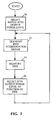
Figure 3 is a flow chart of a method of operation of that shown inFig. 1 . - Referring to
Fig. 1 , a block diagram ofRFID reader 2 is illustrated includingantenna 4, dualdirectional coupler 6,transmitter 8,signal processor 10,receiver 12, andcontroller 14.Controller 14 controlstransmitter 8 to transmit an RFID interrogation signal at a preselected RF output level.Transmitter 8 sends the RFID interrogation signal through dualdirectional coupler 6, toantenna 4 to be radiated outward. Any RFID marker 5, which receives the RFID interrogation sign, responds with a reply signal that includes identification information. Theforward RF signal 16, which is the transmitted RFID interrogation signal taken from dualdirectional coupler 6, is fed into thesignal processor 10. Dualdirectional coupler 6 is a known device disposed betweenantenna 4 andtransmitter 8 that allows access to the transmitted orforward RF signal 16 and reflectedRF signal 18. Thereflected RF signal 18 from dualdirectional coupler 6 is fed into thesignal processor 10, and intoreceiver 12. ReflectedRF signal 18 is the transmitted RFID interrogation signal that is reflected from objects in the vicinity ofantenna 4.Signal processor 10 takes the ratio of theforward RF signal 16 to thereflected RF signal 18 to determine the SWR. The level of SWR indicates the amount of transmitted signal that is reflected back toantenna 4. Increasing the number or size of objects in the vicinity ofantenna 4 increases the level of SWR. The SWR is then sent to controller 14.Controller 14 uses the SWR to determine the proper RF output power level to select fortransmitter 8. Thecontroller 14 will select a high RF output power level for a high SWR indicating that an object is within the maximum radius from the RFID reader to properly read an RFID marker. - When
transmitter 8 sends the RFID interrogation signal toantenna 4 to be radiated outward, any RFID marker 5 which receives the RFID interrogation signal responds with a reply signal that includes identification information and/or other data. Thereflected RF signal 18, from dualdirectional coupler 6, is sent toreceiver 12. Receiver 12 detects signals from any RFID markers (5) that are included inreflected RF signal 18, and transfers the identification information/data to controller 14 for further processing.Receiver 12 may condition the received RFID signals for proper reading of the information/data by thecontroller 14. - In operation, when the
RFID reader 2 is pointed toward an object to read an RFID marker that is attached, connected, or in some way associated with the object, and the object is within the maximum RFID read range, the SWR will be high due to the reflected RF signal from the object, andcontroller 14 will settransmitter 8 to a high output level. The maximum RFID read range will vary according to the frequency of operation and power level of the specific RFID reader, and is readily determinable by one of ordinary skill in the art. If theRF reader 2 is pointed away from objects, or if the object is beyond the maximum RFID read range, the SWR will be low andcontroller 14 will settransmitter 8 to a low output level. When theRFID reader 2 is being used to read RFID markers, theRFID reader 2 will be pointed toward objects, which may have RFID markers attached, and a high SWR is expected. Therefore, the output power level is set high when theRFID reader 2 is actually being used to read RFID markers. When theRFID reader 2 is not being pointed toward an object and an RFID marker 5 is not attempting to be read, or if the object is beyond the maximum RFID read range, the SWR will be low and thecontroller 14 will set the output power level low. When theRFID reader 2 is being used outdoors, the invention prevents high output power level RF signals to be transmitted into the environment, which can permit the use of theRFID reader 2 in areas that may have stringent RF emission standards. When used indoors, theRFID reader 2 will be set to a low output level if pointing away from objects, such as when pointed out into an expansive warehouse or toward objects that are out of RFID marker read range. Battery powered RFID readers will benefit from the inventive output power level control by only being set to high power mode when an object is within the maximum RFID read range for reading an RFID marker. -
Signal processor 10 andreceiver 12 can be implemented in analog hardware, digital hardware, software, or in a combination of hardware and software, and may take the form of a single signal processor. In one embodiment,controller 14 can take the forward and reflected RF signals and convert them to DC voltages, which are then compared to determine the SWR, which is output to controller 14 as a DC voltage. The SWR can alternately be determined digitally, and the SWR that is sent tocontroller 14 would take the form of a digital word.Controller 14 preferably includes a programmable microprocessor, but can be implemented using analog and/or digital circuitry.Transmitter 8 can be a conventional RFID transmitter adapted to include output power level control fromcontroller 14. Referring toFig. 2 ,controller 14 may includememory 30 to maintain a database of RFID information and data corresponding to an inventory of objects, and/or may interface with a fixed system that includes alarger database 32 of objects and information, which is remote fromRFID reader 2. - Referring to
Fig. 3 , a method of operation of one embodiment of the present invention is illustrated. Instep 20, the initial RF output power level fortransmitter 8 is selected bycontroller 14. The initial RF output power level can be manually selected by an operator or preset in hardware or software. If the output power level is preset to a low level, theRFID reader 2 will always initially operate in a low power mode. Instep 22, the RFID interrogation signal is transmitted. Instep 24, the forward and reflected RF signals are compared by thesignal processor 10 to calculate the SWR. Instep 26, thecontroller 14 selects the output power level according to the calculated SWR. The output power level control fromcontroller 14 can be one of two levels, such as high power for high SWR, and low power for low SWR, or alternately,controller 14 can select an output power level comprising a range that is a function of the calculated SWR. - It is to be understood that variations and modifications of the present invention can be made without departing from the scope of the invention. It is also to be understood that the scope of the invention is not to be interpreted as limited to the specific embodiments disclosed herein, but only in accordance with the appended claims when read in light of the forgoing disclosure.
Claims (13)
- A method for controlling the transmit power level of an RFID reader, comprising:transmitting an RFID interrogation signal at an RFID output power level;receiving an RFID reflected signal;comparing the ratio of said RFID interrogation signal to said RFID reflected signal to determine a standing wave ratio (SWR); and,adjusting the RFID output power level as a function of the SWR, wherein the higher the SWR, the higher the power output level, and the lower the SWR, the lower the power output level.
- The method of claim 1 wherein the RFID output power level of the RFID transmitter is preset to a low power mode.
- The method of claim 1 or claim 2 wherein prior to comparing the ratio of said RFID interrogation signal to said RFID reflected signal, said RFID interrogation signal and said RFID reflected signal are converted to DC voltage levels.
- The method of claim 1 or claim 2 wherein prior to comparing the ratio of said RFID interrogation signal to said RFID reflected signal, said RFID interrogation signal and said RFID reflected signal are converted to digital signals.
- The method of any preceding claim wherein the RFID output power level is adjustable between a low power mode and a high power mode corresponding to a relatively low SWR and a relatively high SWR, respectively, the RFID output power level being determined according to a range that is a function of said SWR.
- An apparatus (2) for controlling the transmit power level of an RFID reader, comprising:transmitter means (8) for transmitting an RFID interrogation signal at an RFID output power level; andreceiver means (12) for receiving an RFID reflected signal;characterized in that said apparatus further comprises:processor means (10) for comparing said RFID interrogation signal and said RFID reflected signal to determine a standing wave ratio (SWR); and,controller means (14) for adjusting the RFID output power level as a function of said SWR, wherein the higher the SWR, the higher the power output level, and the lower the SWR, the lower the power output level.
- The apparatus (2) of claim 6 wherein the RFID output power level is preset to a low power mode.
- The apparatus of claim 6 or claim 7 wherein said processor means (10) includes means for converting said RFID interrogation signal and said RFID reflected signal to DC voltage levels.
- The apparatus of claim 6 or claim 7 wherein said processor means (10) includes means for converting said RFID interrogation signal and said RFID reflected signal to digital signals.
- The apparatus of any preceding claim wherein the RFID output power level is adjustable between a low power mode and a high power mode corresponding to a relatively low SWR and a relatively high SWR, respectively, the RFID output power level being determined according to a range that is a function of said SWR.
- The apparatus of any of claims 6-10 wherein said RFID reflected signal includes RFID data from an RFID marker.
- The apparatus of any of claims 6-11 and further including a memory (30) for storing a database of information corresponding to an inventory of objects, said database storing an indication of said RFID data received by said receiver from said RFID marker.
- The apparatus of claim 12 wherein said database (32) of information is located remotely from said RFID reader.
Applications Claiming Priority (3)
| Application Number | Priority Date | Filing Date | Title |
|---|---|---|---|
| US55923500A | 2000-04-26 | 2000-04-26 | |
| US559235 | 2000-04-26 | ||
| PCT/US2001/013078 WO2001082213A2 (en) | 2000-04-26 | 2001-04-23 | Rfid reader output control apparatus and method |
Publications (2)
| Publication Number | Publication Date |
|---|---|
| EP1277163A2 EP1277163A2 (en) | 2003-01-22 |
| EP1277163B1 true EP1277163B1 (en) | 2010-11-24 |
Family
ID=24232832
Family Applications (1)
| Application Number | Title | Priority Date | Filing Date |
|---|---|---|---|
| EP01927302A Expired - Lifetime EP1277163B1 (en) | 2000-04-26 | 2001-04-23 | Rfid reader output control apparatus and method |
Country Status (8)
| Country | Link |
|---|---|
| EP (1) | EP1277163B1 (en) |
| JP (1) | JP4588963B2 (en) |
| CN (1) | CN1423792A (en) |
| AU (2) | AU2001253769B2 (en) |
| BR (1) | BR0109557A (en) |
| CA (1) | CA2403535A1 (en) |
| DE (1) | DE60143518D1 (en) |
| WO (1) | WO2001082213A2 (en) |
Families Citing this family (17)
| Publication number | Priority date | Publication date | Assignee | Title |
|---|---|---|---|---|
| US6681107B2 (en) | 2000-12-06 | 2004-01-20 | Xybernaut Corporation | System and method of accessing and recording messages at coordinate way points |
| US6377793B1 (en) | 2000-12-06 | 2002-04-23 | Xybernaut Corporation | System and method of accessing and recording messages at coordinate way points |
| KR100584328B1 (en) * | 2003-10-07 | 2006-05-26 | 삼성전자주식회사 | Mobile terminal circuit combined with radio frequency identification tag and wireless identification method in mobile terminal |
| US7215249B2 (en) | 2003-11-19 | 2007-05-08 | Alien Technology Corporation | Radio frequency identification reader |
| JP2006033143A (en) * | 2004-07-13 | 2006-02-02 | Sharp Corp | Wireless identification device and wireless identification device processing apparatus |
| DE602005016830D1 (en) * | 2004-11-19 | 2009-11-05 | Sensormatic Electronics Corp | METHOD AND HARDWARE FOR COMMUNICATING WITH RETURN RFID READERS |
| US20060220793A1 (en) * | 2005-03-30 | 2006-10-05 | Samsung Electronics Co., Ltd. | Mobile radio frequency identification reader, portable terminal having the same, and FR transmission power setting method thereof |
| JP4636241B2 (en) * | 2005-03-31 | 2011-02-23 | 日本電気株式会社 | Communication restriction system and communication restriction method |
| EP1872308A2 (en) * | 2005-04-21 | 2008-01-02 | Skyetek, Inc | System and method for combining rfid tag memory |
| US7659819B2 (en) | 2005-04-21 | 2010-02-09 | Skyetek, Inc. | RFID reader operating system and associated architecture |
| EP1987468B1 (en) * | 2006-02-15 | 2018-05-23 | Tyco Fire & Security GmbH | Rf switched rfid multiplexer |
| DE102006040180A1 (en) | 2006-08-26 | 2008-03-13 | Nordenia Deutschland Gronau Gmbh | Method for contactless testing of webs mounted on a web |
| JP4257378B1 (en) * | 2007-10-02 | 2009-04-22 | 株式会社神戸製鋼所 | RFID tag detection method, RFID tag detection system |
| FR2990785B1 (en) * | 2012-05-21 | 2014-05-02 | Schneider Electric Ind Sas | DATA EXCHANGE SYSTEM |
| CN103646227B (en) * | 2013-12-30 | 2016-09-28 | 无锡清华信息科学与技术国家实验室物联网技术中心 | Energy-efficient recognition methods in radio frequency identification system |
| JP6530309B2 (en) * | 2015-12-01 | 2019-06-12 | トヨタ自動車株式会社 | Parts management system |
| GB202014150D0 (en) * | 2020-09-09 | 2020-10-21 | Ifpl Group Ltd | Contactless reader |
Family Cites Families (6)
| Publication number | Priority date | Publication date | Assignee | Title |
|---|---|---|---|---|
| JPS647718A (en) * | 1987-06-29 | 1989-01-11 | Nec Corp | Transmitting power control circuit for radiocommunication equipment |
| JPH04142121A (en) * | 1990-10-02 | 1992-05-15 | Sharp Corp | Transmitter/receiver |
| JPH08191259A (en) * | 1995-01-11 | 1996-07-23 | Sony Chem Corp | Transceiver for non-contact type IC card system |
| US5864580A (en) * | 1996-08-26 | 1999-01-26 | Hid Corporation | Miniature wireless modem |
| JPH11146580A (en) * | 1997-11-06 | 1999-05-28 | Kokusai Electric Co Ltd | Reader / writer |
| US6476708B1 (en) * | 1998-03-20 | 2002-11-05 | Hid Corporation | Detection of an RFID device by an RF reader unit operating in a reduced power state |
-
2001
- 2001-04-23 BR BR0109557-9A patent/BR0109557A/en not_active Application Discontinuation
- 2001-04-23 DE DE60143518T patent/DE60143518D1/en not_active Expired - Lifetime
- 2001-04-23 CA CA002403535A patent/CA2403535A1/en not_active Abandoned
- 2001-04-23 JP JP2001579224A patent/JP4588963B2/en not_active Expired - Fee Related
- 2001-04-23 CN CN 01808099 patent/CN1423792A/en active Pending
- 2001-04-23 AU AU2001253769A patent/AU2001253769B2/en not_active Ceased
- 2001-04-23 WO PCT/US2001/013078 patent/WO2001082213A2/en not_active Ceased
- 2001-04-23 AU AU5376901A patent/AU5376901A/en active Pending
- 2001-04-23 EP EP01927302A patent/EP1277163B1/en not_active Expired - Lifetime
Non-Patent Citations (1)
| Title |
|---|
| None * |
Also Published As
| Publication number | Publication date |
|---|---|
| WO2001082213A3 (en) | 2002-03-21 |
| CA2403535A1 (en) | 2001-11-01 |
| JP4588963B2 (en) | 2010-12-01 |
| AU5376901A (en) | 2001-11-07 |
| JP2003532203A (en) | 2003-10-28 |
| BR0109557A (en) | 2003-06-03 |
| DE60143518D1 (en) | 2011-01-05 |
| AU2001253769B2 (en) | 2006-09-21 |
| EP1277163A2 (en) | 2003-01-22 |
| WO2001082213A2 (en) | 2001-11-01 |
| CN1423792A (en) | 2003-06-11 |
Similar Documents
| Publication | Publication Date | Title |
|---|---|---|
| AU2001253769B2 (en) | Rfid reader output control apparatus and method | |
| AU2001253769A1 (en) | RFID reader output control apparatus and method | |
| US6486769B1 (en) | Method and system for automatic adjustment and diagnosis of radio frequency identification systems using programmable checktags | |
| EP1527616B1 (en) | Pulsed power method for increased read range for a radio frequency identification reader | |
| EP1851691B1 (en) | Radio-frequency identification (rfid) tag employing unique reception window and method therefor | |
| US8446256B2 (en) | Multiplexing radio frequency signals | |
| US20060187049A1 (en) | Circuit arrangement and method for supplying power to a transponder | |
| US20070247286A1 (en) | RFID tag receive signal strength indicator | |
| KR102400727B1 (en) | Adaptive rfid reader | |
| US20110090063A1 (en) | Apparatus and method using histogram-based techniques for avoiding overpolling | |
| US20070273481A1 (en) | RFID tag with programmable read range | |
| US20130122813A1 (en) | Network node for a wireless sensor network | |
| US20240430813A1 (en) | Method for ambient iot based communication, and device | |
| JPH11344562A (en) | Maximum output variable challenge responder | |
| EP2472437A2 (en) | Radio frequency identification system | |
| EP3093799A1 (en) | Rfid transponder, rfid transponder arrangement and method for communication between an rfid transponder and a reading device | |
| KR101239131B1 (en) | Rfid reader and method for controlling gain therof | |
| US8717144B2 (en) | RFID system with distributed readers | |
| CN105929387B (en) | Self application distance measuring method is identified based on RFID power emission shelves in tunnel | |
| US20100194534A1 (en) | Radio frequency identification system provided for access control | |
| JPH05126945A (en) | Data transmitter and interrogator used therefor | |
| JP2006324821A (en) | Wireless tag communication device | |
| HK1055168A (en) | Rfid reader output control apparatus and method | |
| KR101757196B1 (en) | Radio Frequency Identification Reader | |
| KR101990909B1 (en) | System for asset management with low power consumption |
Legal Events
| Date | Code | Title | Description |
|---|---|---|---|
| PUAI | Public reference made under article 153(3) epc to a published international application that has entered the european phase |
Free format text: ORIGINAL CODE: 0009012 |
|
| 17P | Request for examination filed |
Effective date: 20021004 |
|
| AK | Designated contracting states |
Kind code of ref document: A2 Designated state(s): AT BE CH CY DE DK ES FI FR GB GR IE IT LI LU MC NL PT SE TR |
|
| RAP1 | Party data changed (applicant data changed or rights of an application transferred) |
Owner name: SENSORMATIC ELECTRONICS CORPORATION |
|
| RIN1 | Information on inventor provided before grant (corrected) |
Inventor name: SHAFER, G., MARK |
|
| RBV | Designated contracting states (corrected) |
Designated state(s): DE FR GB SE |
|
| 17Q | First examination report despatched |
Effective date: 20070307 |
|
| RAP1 | Party data changed (applicant data changed or rights of an application transferred) |
Owner name: SENSORMATIC ELECTRONICS, LLC |
|
| GRAP | Despatch of communication of intention to grant a patent |
Free format text: ORIGINAL CODE: EPIDOSNIGR1 |
|
| GRAS | Grant fee paid |
Free format text: ORIGINAL CODE: EPIDOSNIGR3 |
|
| GRAA | (expected) grant |
Free format text: ORIGINAL CODE: 0009210 |
|
| AK | Designated contracting states |
Kind code of ref document: B1 Designated state(s): DE FR GB SE |
|
| REG | Reference to a national code |
Ref country code: GB Ref legal event code: FG4D |
|
| RAP2 | Party data changed (patent owner data changed or rights of a patent transferred) |
Owner name: SENSORMATIC ELECTRONICS, LLC |
|
| REF | Corresponds to: |
Ref document number: 60143518 Country of ref document: DE Date of ref document: 20110105 Kind code of ref document: P |
|
| REG | Reference to a national code |
Ref country code: SE Ref legal event code: TRGR |
|
| PGFP | Annual fee paid to national office [announced via postgrant information from national office to epo] |
Ref country code: DE Payment date: 20110427 Year of fee payment: 11 Ref country code: SE Payment date: 20110425 Year of fee payment: 11 Ref country code: FR Payment date: 20110504 Year of fee payment: 11 |
|
| PGFP | Annual fee paid to national office [announced via postgrant information from national office to epo] |
Ref country code: GB Payment date: 20110426 Year of fee payment: 11 |
|
| PLBE | No opposition filed within time limit |
Free format text: ORIGINAL CODE: 0009261 |
|
| STAA | Information on the status of an ep patent application or granted ep patent |
Free format text: STATUS: NO OPPOSITION FILED WITHIN TIME LIMIT |
|
| 26N | No opposition filed |
Effective date: 20110825 |
|
| REG | Reference to a national code |
Ref country code: DE Ref legal event code: R097 Ref document number: 60143518 Country of ref document: DE Effective date: 20110825 |
|
| REG | Reference to a national code |
Ref country code: SE Ref legal event code: EUG |
|
| GBPC | Gb: european patent ceased through non-payment of renewal fee |
Effective date: 20120423 |
|
| REG | Reference to a national code |
Ref country code: FR Ref legal event code: ST Effective date: 20121228 |
|
| PG25 | Lapsed in a contracting state [announced via postgrant information from national office to epo] |
Ref country code: GB Free format text: LAPSE BECAUSE OF NON-PAYMENT OF DUE FEES Effective date: 20120423 |
|
| REG | Reference to a national code |
Ref country code: DE Ref legal event code: R119 Ref document number: 60143518 Country of ref document: DE Effective date: 20121101 |
|
| PG25 | Lapsed in a contracting state [announced via postgrant information from national office to epo] |
Ref country code: SE Free format text: LAPSE BECAUSE OF NON-PAYMENT OF DUE FEES Effective date: 20120424 Ref country code: FR Free format text: LAPSE BECAUSE OF NON-PAYMENT OF DUE FEES Effective date: 20120430 |
|
| PG25 | Lapsed in a contracting state [announced via postgrant information from national office to epo] |
Ref country code: DE Free format text: LAPSE BECAUSE OF NON-PAYMENT OF DUE FEES Effective date: 20121101 |