EP1276704B1 - Process for the production of a braking band with venting passages and braking band obtained with said process - Google Patents
Process for the production of a braking band with venting passages and braking band obtained with said process Download PDFInfo
- Publication number
- EP1276704B1 EP1276704B1 EP00987633A EP00987633A EP1276704B1 EP 1276704 B1 EP1276704 B1 EP 1276704B1 EP 00987633 A EP00987633 A EP 00987633A EP 00987633 A EP00987633 A EP 00987633A EP 1276704 B1 EP1276704 B1 EP 1276704B1
- Authority
- EP
- European Patent Office
- Prior art keywords
- braking band
- core
- production
- moulding
- mould
- Prior art date
- Legal status (The legal status is an assumption and is not a legal conclusion. Google has not performed a legal analysis and makes no representation as to the accuracy of the status listed.)
- Expired - Lifetime
Links
- 238000000034 method Methods 0.000 title claims abstract description 52
- 238000004519 manufacturing process Methods 0.000 title claims abstract description 32
- 238000013022 venting Methods 0.000 title claims abstract description 29
- 238000000465 moulding Methods 0.000 claims abstract description 50
- 239000011265 semifinished product Substances 0.000 claims abstract description 26
- 239000010703 silicon Substances 0.000 claims abstract description 20
- 229910052710 silicon Inorganic materials 0.000 claims abstract description 20
- 238000010304 firing Methods 0.000 claims abstract description 19
- 238000001764 infiltration Methods 0.000 claims abstract description 7
- 230000008595 infiltration Effects 0.000 claims abstract description 6
- 230000004927 fusion Effects 0.000 claims abstract description 4
- 239000000203 mixture Substances 0.000 claims description 40
- 230000003014 reinforcing effect Effects 0.000 claims description 28
- 230000002093 peripheral effect Effects 0.000 claims description 25
- 239000011230 binding agent Substances 0.000 claims description 13
- 239000000463 material Substances 0.000 claims description 12
- 229920005989 resin Polymers 0.000 claims description 12
- 239000011347 resin Substances 0.000 claims description 12
- OKTJSMMVPCPJKN-UHFFFAOYSA-N Carbon Chemical compound [C] OKTJSMMVPCPJKN-UHFFFAOYSA-N 0.000 claims description 10
- 229910052799 carbon Inorganic materials 0.000 claims description 9
- 239000004744 fabric Substances 0.000 claims description 7
- 229920001568 phenolic resin Polymers 0.000 claims description 7
- 239000005011 phenolic resin Substances 0.000 claims description 7
- 239000000047 product Substances 0.000 claims description 7
- 239000007788 liquid Substances 0.000 claims description 6
- 238000004026 adhesive bonding Methods 0.000 claims description 5
- 229920001187 thermosetting polymer Polymers 0.000 claims description 5
- KXGFMDJXCMQABM-UHFFFAOYSA-N 2-methoxy-6-methylphenol Chemical compound [CH]OC1=CC=CC([CH])=C1O KXGFMDJXCMQABM-UHFFFAOYSA-N 0.000 claims description 4
- 238000000151 deposition Methods 0.000 claims description 4
- BASFCYQUMIYNBI-UHFFFAOYSA-N platinum Chemical compound [Pt] BASFCYQUMIYNBI-UHFFFAOYSA-N 0.000 claims description 4
- 229910010271 silicon carbide Inorganic materials 0.000 claims description 4
- 239000002023 wood Substances 0.000 claims description 4
- 239000004745 nonwoven fabric Substances 0.000 claims description 3
- 244000025254 Cannabis sativa Species 0.000 claims description 2
- 235000012766 Cannabis sativa ssp. sativa var. sativa Nutrition 0.000 claims description 2
- 235000012765 Cannabis sativa ssp. sativa var. spontanea Nutrition 0.000 claims description 2
- 229910052581 Si3N4 Inorganic materials 0.000 claims description 2
- 229910034327 TiC Inorganic materials 0.000 claims description 2
- 235000009120 camo Nutrition 0.000 claims description 2
- 239000003575 carbonaceous material Substances 0.000 claims description 2
- 235000005607 chanvre indien Nutrition 0.000 claims description 2
- 239000011487 hemp Substances 0.000 claims description 2
- 239000007769 metal material Substances 0.000 claims description 2
- 229910003465 moissanite Inorganic materials 0.000 claims description 2
- 229910052697 platinum Inorganic materials 0.000 claims description 2
- 238000012545 processing Methods 0.000 claims description 2
- 235000013311 vegetables Nutrition 0.000 claims description 2
- XUIMIQQOPSSXEZ-UHFFFAOYSA-N Silicon Chemical compound [Si] XUIMIQQOPSSXEZ-UHFFFAOYSA-N 0.000 description 17
- 239000010410 layer Substances 0.000 description 14
- 239000000654 additive Substances 0.000 description 5
- 238000000197 pyrolysis Methods 0.000 description 5
- XKRFYHLGVUSROY-UHFFFAOYSA-N Argon Chemical compound [Ar] XKRFYHLGVUSROY-UHFFFAOYSA-N 0.000 description 4
- IJGRMHOSHXDMSA-UHFFFAOYSA-N Atomic nitrogen Chemical compound N#N IJGRMHOSHXDMSA-UHFFFAOYSA-N 0.000 description 4
- 230000000295 complement effect Effects 0.000 description 4
- 230000006835 compression Effects 0.000 description 3
- 238000007906 compression Methods 0.000 description 3
- -1 for example Polymers 0.000 description 3
- 238000010438 heat treatment Methods 0.000 description 3
- 239000011295 pitch Substances 0.000 description 3
- 239000000843 powder Substances 0.000 description 3
- 239000007787 solid Substances 0.000 description 3
- 229910052786 argon Inorganic materials 0.000 description 2
- 230000015572 biosynthetic process Effects 0.000 description 2
- 239000007789 gas Substances 0.000 description 2
- 229910052757 nitrogen Inorganic materials 0.000 description 2
- 229920002239 polyacrylonitrile Polymers 0.000 description 2
- 229920002635 polyurethane Polymers 0.000 description 2
- 239000004814 polyurethane Substances 0.000 description 2
- 239000011148 porous material Substances 0.000 description 2
- 238000002360 preparation method Methods 0.000 description 2
- 230000000644 propagated effect Effects 0.000 description 2
- HBMJWWWQQXIZIP-UHFFFAOYSA-N silicon carbide Chemical compound [Si+]#[C-] HBMJWWWQQXIZIP-UHFFFAOYSA-N 0.000 description 2
- 239000000126 substance Substances 0.000 description 2
- 239000004925 Acrylic resin Substances 0.000 description 1
- 229920000178 Acrylic resin Polymers 0.000 description 1
- 229910000838 Al alloy Inorganic materials 0.000 description 1
- RYGMFSIKBFXOCR-UHFFFAOYSA-N Copper Chemical compound [Cu] RYGMFSIKBFXOCR-UHFFFAOYSA-N 0.000 description 1
- 239000004793 Polystyrene Substances 0.000 description 1
- 229910000676 Si alloy Inorganic materials 0.000 description 1
- 239000012790 adhesive layer Substances 0.000 description 1
- 230000004931 aggregating effect Effects 0.000 description 1
- 239000004411 aluminium Substances 0.000 description 1
- XAGFODPZIPBFFR-UHFFFAOYSA-N aluminium Chemical compound [Al] XAGFODPZIPBFFR-UHFFFAOYSA-N 0.000 description 1
- 238000005452 bending Methods 0.000 description 1
- 239000011204 carbon fibre-reinforced silicon carbide Substances 0.000 description 1
- 238000003763 carbonization Methods 0.000 description 1
- 230000015556 catabolic process Effects 0.000 description 1
- 229910010293 ceramic material Inorganic materials 0.000 description 1
- 238000004891 communication Methods 0.000 description 1
- 239000002131 composite material Substances 0.000 description 1
- 238000007796 conventional method Methods 0.000 description 1
- 229910052802 copper Inorganic materials 0.000 description 1
- 239000010949 copper Substances 0.000 description 1
- 238000006731 degradation reaction Methods 0.000 description 1
- 239000010432 diamond Substances 0.000 description 1
- 230000000694 effects Effects 0.000 description 1
- 238000004880 explosion Methods 0.000 description 1
- 239000000945 filler Substances 0.000 description 1
- 238000007667 floating Methods 0.000 description 1
- 238000004952 furnace firing Methods 0.000 description 1
- 239000003292 glue Substances 0.000 description 1
- 239000008187 granular material Substances 0.000 description 1
- 229910002804 graphite Inorganic materials 0.000 description 1
- 239000010439 graphite Substances 0.000 description 1
- 230000017525 heat dissipation Effects 0.000 description 1
- 238000010348 incorporation Methods 0.000 description 1
- 239000011261 inert gas Substances 0.000 description 1
- 229910010272 inorganic material Inorganic materials 0.000 description 1
- 239000011147 inorganic material Substances 0.000 description 1
- 230000003993 interaction Effects 0.000 description 1
- 238000005304 joining Methods 0.000 description 1
- 239000000155 melt Substances 0.000 description 1
- 239000002184 metal Substances 0.000 description 1
- 229910052751 metal Inorganic materials 0.000 description 1
- 150000004767 nitrides Chemical class 0.000 description 1
- 239000012188 paraffin wax Substances 0.000 description 1
- 239000002245 particle Substances 0.000 description 1
- 239000008188 pellet Substances 0.000 description 1
- ISWSIDIOOBJBQZ-UHFFFAOYSA-N phenol group Chemical group C1(=CC=CC=C1)O ISWSIDIOOBJBQZ-UHFFFAOYSA-N 0.000 description 1
- 229920001709 polysilazane Polymers 0.000 description 1
- 229920002223 polystyrene Polymers 0.000 description 1
- 230000001681 protective effect Effects 0.000 description 1
- 239000011241 protective layer Substances 0.000 description 1
- 230000001105 regulatory effect Effects 0.000 description 1
- 239000000725 suspension Substances 0.000 description 1
- 239000004753 textile Substances 0.000 description 1
Images


Classifications
-
- F—MECHANICAL ENGINEERING; LIGHTING; HEATING; WEAPONS; BLASTING
- F16—ENGINEERING ELEMENTS AND UNITS; GENERAL MEASURES FOR PRODUCING AND MAINTAINING EFFECTIVE FUNCTIONING OF MACHINES OR INSTALLATIONS; THERMAL INSULATION IN GENERAL
- F16D—COUPLINGS FOR TRANSMITTING ROTATION; CLUTCHES; BRAKES
- F16D65/00—Parts or details
- F16D65/02—Braking members; Mounting thereof
- F16D65/12—Discs; Drums for disc brakes
-
- B—PERFORMING OPERATIONS; TRANSPORTING
- B32—LAYERED PRODUCTS
- B32B—LAYERED PRODUCTS, i.e. PRODUCTS BUILT-UP OF STRATA OF FLAT OR NON-FLAT, e.g. CELLULAR OR HONEYCOMB, FORM
- B32B18/00—Layered products essentially comprising ceramics, e.g. refractory products
-
- C—CHEMISTRY; METALLURGY
- C04—CEMENTS; CONCRETE; ARTIFICIAL STONE; CERAMICS; REFRACTORIES
- C04B—LIME, MAGNESIA; SLAG; CEMENTS; COMPOSITIONS THEREOF, e.g. MORTARS, CONCRETE OR LIKE BUILDING MATERIALS; ARTIFICIAL STONE; CERAMICS; REFRACTORIES; TREATMENT OF NATURAL STONE
- C04B35/00—Shaped ceramic products characterised by their composition; Ceramics compositions; Processing powders of inorganic compounds preparatory to the manufacturing of ceramic products
- C04B35/515—Shaped ceramic products characterised by their composition; Ceramics compositions; Processing powders of inorganic compounds preparatory to the manufacturing of ceramic products based on non-oxide ceramics
- C04B35/56—Shaped ceramic products characterised by their composition; Ceramics compositions; Processing powders of inorganic compounds preparatory to the manufacturing of ceramic products based on non-oxide ceramics based on carbides or oxycarbides
- C04B35/565—Shaped ceramic products characterised by their composition; Ceramics compositions; Processing powders of inorganic compounds preparatory to the manufacturing of ceramic products based on non-oxide ceramics based on carbides or oxycarbides based on silicon carbide
- C04B35/573—Shaped ceramic products characterised by their composition; Ceramics compositions; Processing powders of inorganic compounds preparatory to the manufacturing of ceramic products based on non-oxide ceramics based on carbides or oxycarbides based on silicon carbide obtained by reaction sintering or recrystallisation
-
- C—CHEMISTRY; METALLURGY
- C04—CEMENTS; CONCRETE; ARTIFICIAL STONE; CERAMICS; REFRACTORIES
- C04B—LIME, MAGNESIA; SLAG; CEMENTS; COMPOSITIONS THEREOF, e.g. MORTARS, CONCRETE OR LIKE BUILDING MATERIALS; ARTIFICIAL STONE; CERAMICS; REFRACTORIES; TREATMENT OF NATURAL STONE
- C04B35/00—Shaped ceramic products characterised by their composition; Ceramics compositions; Processing powders of inorganic compounds preparatory to the manufacturing of ceramic products
- C04B35/622—Forming processes; Processing powders of inorganic compounds preparatory to the manufacturing of ceramic products
- C04B35/626—Preparing or treating the powders individually or as batches ; preparing or treating macroscopic reinforcing agents for ceramic products, e.g. fibres; mechanical aspects section B
- C04B35/63—Preparing or treating the powders individually or as batches ; preparing or treating macroscopic reinforcing agents for ceramic products, e.g. fibres; mechanical aspects section B using additives specially adapted for forming the products, e.g.. binder binders
- C04B35/632—Organic additives
- C04B35/634—Polymers
- C04B35/63404—Polymers obtained by reactions only involving carbon-to-carbon unsaturated bonds
- C04B35/63424—Polyacrylates; Polymethacrylates
-
- C—CHEMISTRY; METALLURGY
- C04—CEMENTS; CONCRETE; ARTIFICIAL STONE; CERAMICS; REFRACTORIES
- C04B—LIME, MAGNESIA; SLAG; CEMENTS; COMPOSITIONS THEREOF, e.g. MORTARS, CONCRETE OR LIKE BUILDING MATERIALS; ARTIFICIAL STONE; CERAMICS; REFRACTORIES; TREATMENT OF NATURAL STONE
- C04B35/00—Shaped ceramic products characterised by their composition; Ceramics compositions; Processing powders of inorganic compounds preparatory to the manufacturing of ceramic products
- C04B35/622—Forming processes; Processing powders of inorganic compounds preparatory to the manufacturing of ceramic products
- C04B35/626—Preparing or treating the powders individually or as batches ; preparing or treating macroscopic reinforcing agents for ceramic products, e.g. fibres; mechanical aspects section B
- C04B35/63—Preparing or treating the powders individually or as batches ; preparing or treating macroscopic reinforcing agents for ceramic products, e.g. fibres; mechanical aspects section B using additives specially adapted for forming the products, e.g.. binder binders
- C04B35/632—Organic additives
- C04B35/634—Polymers
- C04B35/63404—Polymers obtained by reactions only involving carbon-to-carbon unsaturated bonds
- C04B35/63432—Polystyrenes
-
- C—CHEMISTRY; METALLURGY
- C04—CEMENTS; CONCRETE; ARTIFICIAL STONE; CERAMICS; REFRACTORIES
- C04B—LIME, MAGNESIA; SLAG; CEMENTS; COMPOSITIONS THEREOF, e.g. MORTARS, CONCRETE OR LIKE BUILDING MATERIALS; ARTIFICIAL STONE; CERAMICS; REFRACTORIES; TREATMENT OF NATURAL STONE
- C04B35/00—Shaped ceramic products characterised by their composition; Ceramics compositions; Processing powders of inorganic compounds preparatory to the manufacturing of ceramic products
- C04B35/622—Forming processes; Processing powders of inorganic compounds preparatory to the manufacturing of ceramic products
- C04B35/626—Preparing or treating the powders individually or as batches ; preparing or treating macroscopic reinforcing agents for ceramic products, e.g. fibres; mechanical aspects section B
- C04B35/63—Preparing or treating the powders individually or as batches ; preparing or treating macroscopic reinforcing agents for ceramic products, e.g. fibres; mechanical aspects section B using additives specially adapted for forming the products, e.g.. binder binders
- C04B35/632—Organic additives
- C04B35/634—Polymers
- C04B35/63448—Polymers obtained otherwise than by reactions only involving carbon-to-carbon unsaturated bonds
- C04B35/63456—Polyurethanes; Polyisocyanates
-
- C—CHEMISTRY; METALLURGY
- C04—CEMENTS; CONCRETE; ARTIFICIAL STONE; CERAMICS; REFRACTORIES
- C04B—LIME, MAGNESIA; SLAG; CEMENTS; COMPOSITIONS THEREOF, e.g. MORTARS, CONCRETE OR LIKE BUILDING MATERIALS; ARTIFICIAL STONE; CERAMICS; REFRACTORIES; TREATMENT OF NATURAL STONE
- C04B35/00—Shaped ceramic products characterised by their composition; Ceramics compositions; Processing powders of inorganic compounds preparatory to the manufacturing of ceramic products
- C04B35/622—Forming processes; Processing powders of inorganic compounds preparatory to the manufacturing of ceramic products
- C04B35/626—Preparing or treating the powders individually or as batches ; preparing or treating macroscopic reinforcing agents for ceramic products, e.g. fibres; mechanical aspects section B
- C04B35/63—Preparing or treating the powders individually or as batches ; preparing or treating macroscopic reinforcing agents for ceramic products, e.g. fibres; mechanical aspects section B using additives specially adapted for forming the products, e.g.. binder binders
- C04B35/632—Organic additives
- C04B35/634—Polymers
- C04B35/63448—Polymers obtained otherwise than by reactions only involving carbon-to-carbon unsaturated bonds
- C04B35/63472—Condensation polymers of aldehydes or ketones
- C04B35/63476—Phenol-formaldehyde condensation polymers
-
- C—CHEMISTRY; METALLURGY
- C04—CEMENTS; CONCRETE; ARTIFICIAL STONE; CERAMICS; REFRACTORIES
- C04B—LIME, MAGNESIA; SLAG; CEMENTS; COMPOSITIONS THEREOF, e.g. MORTARS, CONCRETE OR LIKE BUILDING MATERIALS; ARTIFICIAL STONE; CERAMICS; REFRACTORIES; TREATMENT OF NATURAL STONE
- C04B35/00—Shaped ceramic products characterised by their composition; Ceramics compositions; Processing powders of inorganic compounds preparatory to the manufacturing of ceramic products
- C04B35/622—Forming processes; Processing powders of inorganic compounds preparatory to the manufacturing of ceramic products
- C04B35/626—Preparing or treating the powders individually or as batches ; preparing or treating macroscopic reinforcing agents for ceramic products, e.g. fibres; mechanical aspects section B
- C04B35/63—Preparing or treating the powders individually or as batches ; preparing or treating macroscopic reinforcing agents for ceramic products, e.g. fibres; mechanical aspects section B using additives specially adapted for forming the products, e.g.. binder binders
- C04B35/632—Organic additives
- C04B35/634—Polymers
- C04B35/63496—Bituminous materials, e.g. tar, pitch
-
- C—CHEMISTRY; METALLURGY
- C04—CEMENTS; CONCRETE; ARTIFICIAL STONE; CERAMICS; REFRACTORIES
- C04B—LIME, MAGNESIA; SLAG; CEMENTS; COMPOSITIONS THEREOF, e.g. MORTARS, CONCRETE OR LIKE BUILDING MATERIALS; ARTIFICIAL STONE; CERAMICS; REFRACTORIES; TREATMENT OF NATURAL STONE
- C04B35/00—Shaped ceramic products characterised by their composition; Ceramics compositions; Processing powders of inorganic compounds preparatory to the manufacturing of ceramic products
- C04B35/622—Forming processes; Processing powders of inorganic compounds preparatory to the manufacturing of ceramic products
- C04B35/64—Burning or sintering processes
- C04B35/645—Pressure sintering
-
- C—CHEMISTRY; METALLURGY
- C04—CEMENTS; CONCRETE; ARTIFICIAL STONE; CERAMICS; REFRACTORIES
- C04B—LIME, MAGNESIA; SLAG; CEMENTS; COMPOSITIONS THEREOF, e.g. MORTARS, CONCRETE OR LIKE BUILDING MATERIALS; ARTIFICIAL STONE; CERAMICS; REFRACTORIES; TREATMENT OF NATURAL STONE
- C04B35/00—Shaped ceramic products characterised by their composition; Ceramics compositions; Processing powders of inorganic compounds preparatory to the manufacturing of ceramic products
- C04B35/71—Ceramic products containing macroscopic reinforcing agents
- C04B35/74—Ceramic products containing macroscopic reinforcing agents containing shaped metallic materials
- C04B35/76—Fibres, filaments, whiskers, platelets, or the like
-
- C—CHEMISTRY; METALLURGY
- C04—CEMENTS; CONCRETE; ARTIFICIAL STONE; CERAMICS; REFRACTORIES
- C04B—LIME, MAGNESIA; SLAG; CEMENTS; COMPOSITIONS THEREOF, e.g. MORTARS, CONCRETE OR LIKE BUILDING MATERIALS; ARTIFICIAL STONE; CERAMICS; REFRACTORIES; TREATMENT OF NATURAL STONE
- C04B35/00—Shaped ceramic products characterised by their composition; Ceramics compositions; Processing powders of inorganic compounds preparatory to the manufacturing of ceramic products
- C04B35/71—Ceramic products containing macroscopic reinforcing agents
- C04B35/78—Ceramic products containing macroscopic reinforcing agents containing non-metallic materials
- C04B35/80—Fibres, filaments, whiskers, platelets, or the like
- C04B35/83—Carbon fibres in a carbon matrix
-
- C—CHEMISTRY; METALLURGY
- C04—CEMENTS; CONCRETE; ARTIFICIAL STONE; CERAMICS; REFRACTORIES
- C04B—LIME, MAGNESIA; SLAG; CEMENTS; COMPOSITIONS THEREOF, e.g. MORTARS, CONCRETE OR LIKE BUILDING MATERIALS; ARTIFICIAL STONE; CERAMICS; REFRACTORIES; TREATMENT OF NATURAL STONE
- C04B37/00—Joining burned ceramic articles with other burned ceramic articles or other articles by heating
- C04B37/008—Joining burned ceramic articles with other burned ceramic articles or other articles by heating by means of an interlayer consisting of an organic adhesive, e.g. phenol resin or pitch
-
- F—MECHANICAL ENGINEERING; LIGHTING; HEATING; WEAPONS; BLASTING
- F16—ENGINEERING ELEMENTS AND UNITS; GENERAL MEASURES FOR PRODUCING AND MAINTAINING EFFECTIVE FUNCTIONING OF MACHINES OR INSTALLATIONS; THERMAL INSULATION IN GENERAL
- F16D—COUPLINGS FOR TRANSMITTING ROTATION; CLUTCHES; BRAKES
- F16D69/00—Friction linings; Attachment thereof; Selection of coacting friction substances or surfaces
- F16D69/02—Composition of linings ; Methods of manufacturing
-
- C—CHEMISTRY; METALLURGY
- C04—CEMENTS; CONCRETE; ARTIFICIAL STONE; CERAMICS; REFRACTORIES
- C04B—LIME, MAGNESIA; SLAG; CEMENTS; COMPOSITIONS THEREOF, e.g. MORTARS, CONCRETE OR LIKE BUILDING MATERIALS; ARTIFICIAL STONE; CERAMICS; REFRACTORIES; TREATMENT OF NATURAL STONE
- C04B2235/00—Aspects relating to ceramic starting mixtures or sintered ceramic products
- C04B2235/02—Composition of constituents of the starting material or of secondary phases of the final product
- C04B2235/30—Constituents and secondary phases not being of a fibrous nature
- C04B2235/48—Organic compounds becoming part of a ceramic after heat treatment, e.g. carbonising phenol resins
- C04B2235/483—Si-containing organic compounds, e.g. silicone resins, (poly)silanes, (poly)siloxanes or (poly)silazanes
-
- C—CHEMISTRY; METALLURGY
- C04—CEMENTS; CONCRETE; ARTIFICIAL STONE; CERAMICS; REFRACTORIES
- C04B—LIME, MAGNESIA; SLAG; CEMENTS; COMPOSITIONS THEREOF, e.g. MORTARS, CONCRETE OR LIKE BUILDING MATERIALS; ARTIFICIAL STONE; CERAMICS; REFRACTORIES; TREATMENT OF NATURAL STONE
- C04B2235/00—Aspects relating to ceramic starting mixtures or sintered ceramic products
- C04B2235/02—Composition of constituents of the starting material or of secondary phases of the final product
- C04B2235/50—Constituents or additives of the starting mixture chosen for their shape or used because of their shape or their physical appearance
- C04B2235/52—Constituents or additives characterised by their shapes
- C04B2235/5208—Fibers
- C04B2235/5212—Organic
-
- C—CHEMISTRY; METALLURGY
- C04—CEMENTS; CONCRETE; ARTIFICIAL STONE; CERAMICS; REFRACTORIES
- C04B—LIME, MAGNESIA; SLAG; CEMENTS; COMPOSITIONS THEREOF, e.g. MORTARS, CONCRETE OR LIKE BUILDING MATERIALS; ARTIFICIAL STONE; CERAMICS; REFRACTORIES; TREATMENT OF NATURAL STONE
- C04B2235/00—Aspects relating to ceramic starting mixtures or sintered ceramic products
- C04B2235/02—Composition of constituents of the starting material or of secondary phases of the final product
- C04B2235/50—Constituents or additives of the starting mixture chosen for their shape or used because of their shape or their physical appearance
- C04B2235/52—Constituents or additives characterised by their shapes
- C04B2235/5208—Fibers
- C04B2235/5216—Inorganic
- C04B2235/524—Non-oxidic, e.g. borides, carbides, silicides or nitrides
- C04B2235/5244—Silicon carbide
-
- C—CHEMISTRY; METALLURGY
- C04—CEMENTS; CONCRETE; ARTIFICIAL STONE; CERAMICS; REFRACTORIES
- C04B—LIME, MAGNESIA; SLAG; CEMENTS; COMPOSITIONS THEREOF, e.g. MORTARS, CONCRETE OR LIKE BUILDING MATERIALS; ARTIFICIAL STONE; CERAMICS; REFRACTORIES; TREATMENT OF NATURAL STONE
- C04B2235/00—Aspects relating to ceramic starting mixtures or sintered ceramic products
- C04B2235/02—Composition of constituents of the starting material or of secondary phases of the final product
- C04B2235/50—Constituents or additives of the starting mixture chosen for their shape or used because of their shape or their physical appearance
- C04B2235/52—Constituents or additives characterised by their shapes
- C04B2235/5208—Fibers
- C04B2235/5216—Inorganic
- C04B2235/524—Non-oxidic, e.g. borides, carbides, silicides or nitrides
- C04B2235/5248—Carbon, e.g. graphite
-
- C—CHEMISTRY; METALLURGY
- C04—CEMENTS; CONCRETE; ARTIFICIAL STONE; CERAMICS; REFRACTORIES
- C04B—LIME, MAGNESIA; SLAG; CEMENTS; COMPOSITIONS THEREOF, e.g. MORTARS, CONCRETE OR LIKE BUILDING MATERIALS; ARTIFICIAL STONE; CERAMICS; REFRACTORIES; TREATMENT OF NATURAL STONE
- C04B2235/00—Aspects relating to ceramic starting mixtures or sintered ceramic products
- C04B2235/02—Composition of constituents of the starting material or of secondary phases of the final product
- C04B2235/50—Constituents or additives of the starting mixture chosen for their shape or used because of their shape or their physical appearance
- C04B2235/52—Constituents or additives characterised by their shapes
- C04B2235/5208—Fibers
- C04B2235/5252—Fibers having a specific pre-form
- C04B2235/5256—Two-dimensional, e.g. woven structures
-
- C—CHEMISTRY; METALLURGY
- C04—CEMENTS; CONCRETE; ARTIFICIAL STONE; CERAMICS; REFRACTORIES
- C04B—LIME, MAGNESIA; SLAG; CEMENTS; COMPOSITIONS THEREOF, e.g. MORTARS, CONCRETE OR LIKE BUILDING MATERIALS; ARTIFICIAL STONE; CERAMICS; REFRACTORIES; TREATMENT OF NATURAL STONE
- C04B2235/00—Aspects relating to ceramic starting mixtures or sintered ceramic products
- C04B2235/02—Composition of constituents of the starting material or of secondary phases of the final product
- C04B2235/50—Constituents or additives of the starting mixture chosen for their shape or used because of their shape or their physical appearance
- C04B2235/52—Constituents or additives characterised by their shapes
- C04B2235/5208—Fibers
- C04B2235/526—Fibers characterised by the length of the fibers
-
- C—CHEMISTRY; METALLURGY
- C04—CEMENTS; CONCRETE; ARTIFICIAL STONE; CERAMICS; REFRACTORIES
- C04B—LIME, MAGNESIA; SLAG; CEMENTS; COMPOSITIONS THEREOF, e.g. MORTARS, CONCRETE OR LIKE BUILDING MATERIALS; ARTIFICIAL STONE; CERAMICS; REFRACTORIES; TREATMENT OF NATURAL STONE
- C04B2235/00—Aspects relating to ceramic starting mixtures or sintered ceramic products
- C04B2235/02—Composition of constituents of the starting material or of secondary phases of the final product
- C04B2235/50—Constituents or additives of the starting mixture chosen for their shape or used because of their shape or their physical appearance
- C04B2235/52—Constituents or additives characterised by their shapes
- C04B2235/5208—Fibers
- C04B2235/5264—Fibers characterised by the diameter of the fibers
-
- C—CHEMISTRY; METALLURGY
- C04—CEMENTS; CONCRETE; ARTIFICIAL STONE; CERAMICS; REFRACTORIES
- C04B—LIME, MAGNESIA; SLAG; CEMENTS; COMPOSITIONS THEREOF, e.g. MORTARS, CONCRETE OR LIKE BUILDING MATERIALS; ARTIFICIAL STONE; CERAMICS; REFRACTORIES; TREATMENT OF NATURAL STONE
- C04B2235/00—Aspects relating to ceramic starting mixtures or sintered ceramic products
- C04B2235/02—Composition of constituents of the starting material or of secondary phases of the final product
- C04B2235/50—Constituents or additives of the starting mixture chosen for their shape or used because of their shape or their physical appearance
- C04B2235/52—Constituents or additives characterised by their shapes
- C04B2235/5208—Fibers
- C04B2235/5268—Orientation of the fibers
-
- C—CHEMISTRY; METALLURGY
- C04—CEMENTS; CONCRETE; ARTIFICIAL STONE; CERAMICS; REFRACTORIES
- C04B—LIME, MAGNESIA; SLAG; CEMENTS; COMPOSITIONS THEREOF, e.g. MORTARS, CONCRETE OR LIKE BUILDING MATERIALS; ARTIFICIAL STONE; CERAMICS; REFRACTORIES; TREATMENT OF NATURAL STONE
- C04B2235/00—Aspects relating to ceramic starting mixtures or sintered ceramic products
- C04B2235/65—Aspects relating to heat treatments of ceramic bodies such as green ceramics or pre-sintered ceramics, e.g. burning, sintering or melting processes
- C04B2235/656—Aspects relating to heat treatments of ceramic bodies such as green ceramics or pre-sintered ceramics, e.g. burning, sintering or melting processes characterised by specific heating conditions during heat treatment
-
- C—CHEMISTRY; METALLURGY
- C04—CEMENTS; CONCRETE; ARTIFICIAL STONE; CERAMICS; REFRACTORIES
- C04B—LIME, MAGNESIA; SLAG; CEMENTS; COMPOSITIONS THEREOF, e.g. MORTARS, CONCRETE OR LIKE BUILDING MATERIALS; ARTIFICIAL STONE; CERAMICS; REFRACTORIES; TREATMENT OF NATURAL STONE
- C04B2235/00—Aspects relating to ceramic starting mixtures or sintered ceramic products
- C04B2235/65—Aspects relating to heat treatments of ceramic bodies such as green ceramics or pre-sintered ceramics, e.g. burning, sintering or melting processes
- C04B2235/658—Atmosphere during thermal treatment
- C04B2235/6581—Total pressure below 1 atmosphere, e.g. vacuum
-
- C—CHEMISTRY; METALLURGY
- C04—CEMENTS; CONCRETE; ARTIFICIAL STONE; CERAMICS; REFRACTORIES
- C04B—LIME, MAGNESIA; SLAG; CEMENTS; COMPOSITIONS THEREOF, e.g. MORTARS, CONCRETE OR LIKE BUILDING MATERIALS; ARTIFICIAL STONE; CERAMICS; REFRACTORIES; TREATMENT OF NATURAL STONE
- C04B2237/00—Aspects relating to ceramic laminates or to joining of ceramic articles with other articles by heating
- C04B2237/30—Composition of layers of ceramic laminates or of ceramic or metallic articles to be joined by heating, e.g. Si substrates
- C04B2237/32—Ceramic
- C04B2237/36—Non-oxidic
- C04B2237/363—Carbon
-
- C—CHEMISTRY; METALLURGY
- C04—CEMENTS; CONCRETE; ARTIFICIAL STONE; CERAMICS; REFRACTORIES
- C04B—LIME, MAGNESIA; SLAG; CEMENTS; COMPOSITIONS THEREOF, e.g. MORTARS, CONCRETE OR LIKE BUILDING MATERIALS; ARTIFICIAL STONE; CERAMICS; REFRACTORIES; TREATMENT OF NATURAL STONE
- C04B2237/00—Aspects relating to ceramic laminates or to joining of ceramic articles with other articles by heating
- C04B2237/30—Composition of layers of ceramic laminates or of ceramic or metallic articles to be joined by heating, e.g. Si substrates
- C04B2237/32—Ceramic
- C04B2237/38—Fiber or whisker reinforced
- C04B2237/385—Carbon or carbon composite
-
- C—CHEMISTRY; METALLURGY
- C04—CEMENTS; CONCRETE; ARTIFICIAL STONE; CERAMICS; REFRACTORIES
- C04B—LIME, MAGNESIA; SLAG; CEMENTS; COMPOSITIONS THEREOF, e.g. MORTARS, CONCRETE OR LIKE BUILDING MATERIALS; ARTIFICIAL STONE; CERAMICS; REFRACTORIES; TREATMENT OF NATURAL STONE
- C04B2237/00—Aspects relating to ceramic laminates or to joining of ceramic articles with other articles by heating
- C04B2237/50—Processing aspects relating to ceramic laminates or to the joining of ceramic articles with other articles by heating
- C04B2237/52—Pre-treatment of the joining surfaces, e.g. cleaning, machining
-
- C—CHEMISTRY; METALLURGY
- C04—CEMENTS; CONCRETE; ARTIFICIAL STONE; CERAMICS; REFRACTORIES
- C04B—LIME, MAGNESIA; SLAG; CEMENTS; COMPOSITIONS THEREOF, e.g. MORTARS, CONCRETE OR LIKE BUILDING MATERIALS; ARTIFICIAL STONE; CERAMICS; REFRACTORIES; TREATMENT OF NATURAL STONE
- C04B2237/00—Aspects relating to ceramic laminates or to joining of ceramic articles with other articles by heating
- C04B2237/50—Processing aspects relating to ceramic laminates or to the joining of ceramic articles with other articles by heating
- C04B2237/61—Joining two substrates of which at least one is porous by infiltrating the porous substrate with a liquid, such as a molten metal, causing bonding of the two substrates, e.g. joining two porous carbon substrates by infiltrating with molten silicon
-
- C—CHEMISTRY; METALLURGY
- C04—CEMENTS; CONCRETE; ARTIFICIAL STONE; CERAMICS; REFRACTORIES
- C04B—LIME, MAGNESIA; SLAG; CEMENTS; COMPOSITIONS THEREOF, e.g. MORTARS, CONCRETE OR LIKE BUILDING MATERIALS; ARTIFICIAL STONE; CERAMICS; REFRACTORIES; TREATMENT OF NATURAL STONE
- C04B2237/00—Aspects relating to ceramic laminates or to joining of ceramic articles with other articles by heating
- C04B2237/50—Processing aspects relating to ceramic laminates or to the joining of ceramic articles with other articles by heating
- C04B2237/62—Forming laminates or joined articles comprising holes, channels or other types of openings
-
- C—CHEMISTRY; METALLURGY
- C04—CEMENTS; CONCRETE; ARTIFICIAL STONE; CERAMICS; REFRACTORIES
- C04B—LIME, MAGNESIA; SLAG; CEMENTS; COMPOSITIONS THEREOF, e.g. MORTARS, CONCRETE OR LIKE BUILDING MATERIALS; ARTIFICIAL STONE; CERAMICS; REFRACTORIES; TREATMENT OF NATURAL STONE
- C04B2237/00—Aspects relating to ceramic laminates or to joining of ceramic articles with other articles by heating
- C04B2237/50—Processing aspects relating to ceramic laminates or to the joining of ceramic articles with other articles by heating
- C04B2237/64—Forming laminates or joined articles comprising grooves or cuts
-
- C—CHEMISTRY; METALLURGY
- C04—CEMENTS; CONCRETE; ARTIFICIAL STONE; CERAMICS; REFRACTORIES
- C04B—LIME, MAGNESIA; SLAG; CEMENTS; COMPOSITIONS THEREOF, e.g. MORTARS, CONCRETE OR LIKE BUILDING MATERIALS; ARTIFICIAL STONE; CERAMICS; REFRACTORIES; TREATMENT OF NATURAL STONE
- C04B2237/00—Aspects relating to ceramic laminates or to joining of ceramic articles with other articles by heating
- C04B2237/50—Processing aspects relating to ceramic laminates or to the joining of ceramic articles with other articles by heating
- C04B2237/76—Forming laminates or joined articles comprising at least one member in the form other than a sheet or disc, e.g. two tubes or a tube and a sheet or disc
- C04B2237/765—Forming laminates or joined articles comprising at least one member in the form other than a sheet or disc, e.g. two tubes or a tube and a sheet or disc at least one member being a tube
-
- F—MECHANICAL ENGINEERING; LIGHTING; HEATING; WEAPONS; BLASTING
- F16—ENGINEERING ELEMENTS AND UNITS; GENERAL MEASURES FOR PRODUCING AND MAINTAINING EFFECTIVE FUNCTIONING OF MACHINES OR INSTALLATIONS; THERMAL INSULATION IN GENERAL
- F16D—COUPLINGS FOR TRANSMITTING ROTATION; CLUTCHES; BRAKES
- F16D65/00—Parts or details
- F16D65/02—Braking members; Mounting thereof
- F16D2065/13—Parts or details of discs or drums
- F16D2065/1304—Structure
- F16D2065/132—Structure layered
-
- F—MECHANICAL ENGINEERING; LIGHTING; HEATING; WEAPONS; BLASTING
- F16—ENGINEERING ELEMENTS AND UNITS; GENERAL MEASURES FOR PRODUCING AND MAINTAINING EFFECTIVE FUNCTIONING OF MACHINES OR INSTALLATIONS; THERMAL INSULATION IN GENERAL
- F16D—COUPLINGS FOR TRANSMITTING ROTATION; CLUTCHES; BRAKES
- F16D65/00—Parts or details
- F16D65/02—Braking members; Mounting thereof
- F16D2065/13—Parts or details of discs or drums
- F16D2065/1304—Structure
- F16D2065/1328—Structure internal cavities, e.g. cooling channels
-
- F—MECHANICAL ENGINEERING; LIGHTING; HEATING; WEAPONS; BLASTING
- F16—ENGINEERING ELEMENTS AND UNITS; GENERAL MEASURES FOR PRODUCING AND MAINTAINING EFFECTIVE FUNCTIONING OF MACHINES OR INSTALLATIONS; THERMAL INSULATION IN GENERAL
- F16D—COUPLINGS FOR TRANSMITTING ROTATION; CLUTCHES; BRAKES
- F16D69/00—Friction linings; Attachment thereof; Selection of coacting friction substances or surfaces
- F16D2069/009—Linings attached to both sides of a central support element, e.g. a carrier plate
-
- F—MECHANICAL ENGINEERING; LIGHTING; HEATING; WEAPONS; BLASTING
- F16—ENGINEERING ELEMENTS AND UNITS; GENERAL MEASURES FOR PRODUCING AND MAINTAINING EFFECTIVE FUNCTIONING OF MACHINES OR INSTALLATIONS; THERMAL INSULATION IN GENERAL
- F16D—COUPLINGS FOR TRANSMITTING ROTATION; CLUTCHES; BRAKES
- F16D2200/00—Materials; Production methods therefor
- F16D2200/0034—Materials; Production methods therefor non-metallic
- F16D2200/0039—Ceramics
-
- F—MECHANICAL ENGINEERING; LIGHTING; HEATING; WEAPONS; BLASTING
- F16—ENGINEERING ELEMENTS AND UNITS; GENERAL MEASURES FOR PRODUCING AND MAINTAINING EFFECTIVE FUNCTIONING OF MACHINES OR INSTALLATIONS; THERMAL INSULATION IN GENERAL
- F16D—COUPLINGS FOR TRANSMITTING ROTATION; CLUTCHES; BRAKES
- F16D2250/00—Manufacturing; Assembly
- F16D2250/0092—Tools or machines for producing linings
Definitions
- the present invention relates to a process for the production of a braking band for a brake disk with venting passages, and a braking band produced by the process.
- the present invention relates to a process for the production of a braking band which has venting passages and is made of a ceramic material such as, for example C/SiC.
- the first process provides for the moulding of the braking band as a solid body and for the subsequent formation of radial and non-radial holes lying in a central plane of the thickness of the band and thus constituting the venting passages.
- the second process provides for a first step for the moulding of two reflectively symmetrical portions of the braking band having grooves in their facing surfaces.
- the two portions are then brought into contact and glued to form the finished product in which each groove of each of the portions represents one half of a venting duct.
- the second process has the great disadvantage that it is necessary to glue two portions of a braking band which, since they are formed separately, may not correspond and may therefore fit together incorrectly. This could give rise to a product which might easily be subject to dangerous detachment of these two portions.
- DE-A-4 438 456 discloses a separately moulded core and friction bodies of a carbon friction unit can be joined by infiltration with molten Si.
- DE-A-19 834 571 discloses a mould containing a cavity between two punches, a floating die and an anular insert.
- the problem upon which the present invention is based is therefore to devise a process for the production of braking bands which has characteristics such as to satisfy the above-mentioned requirements and at the same time to overcome the disadvantages of the processes of the prior art.
- the process according to the present invention provides for the moulding of a core in which venting passages are defined and for the subsequent moulding of two covers onto the core so as to produce a semi-finished product with a "sandwich" structure.
- the core is advantageously produced by a process which provides, first of all, for the moulding of two half-cores in which grooves of the venting passages are defined and, subsequently, for the joining-together of the half-cores to produce the core.
- the mixture for moulding the half-cores preferably comprises fibres and/or filaments of carbon-based materials selected from the group consisting of wood and products of the processing of wood, vegetable fibres, thermosetting resins, and products produced by pyrolysis of substances of synthetic origin such as, for example, polyacrylonitrile (PAN) and polysilazane.
- PAN polyacrylonitrile
- these materials comprise sawdust or chippings and the like, hemp, and similar textile fibres.
- the filaments derived from these materials are variable from 3000 to 50000 units and have diameters of between 2 and 3 ⁇ m. These filaments may also be chopped to lengths of less than 30 mm.
- aggregating resin such as, for example, polyurethane or, more preferably, a phenolic resin, pitches, and other additives.
- this mixture is deposited in the moulding cavity of the mould and subjected to heating to temperatures generally of between 80°C and 180°C, and to compression to produce a half-core.
- a further half-core is produced by repeating precisely the same process as described above.
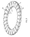
- the two half-cores thus produced are then juxtaposed so as to fit the grooves of the venting passages together and are fixed to one another as shown schematically in Figures 2 and 3, preferably by gluing with a liquid thermosetting resin. More preferably, the resin is a phenolic resin.
- the gluing resin advantageously sets immediately. There is consequently no need for further heating processes to bring about setting of the resin.
- the next step of the process for the production of a braking band according to the present invention requires the provision of a further mould in which the core previously produced is inserted in order for two covers to be moulded around the core.
- cover is intended to define the outer portion of the braking band which covers the core of the band and therefore constitutes the braking surface which is acted on, for example, by the pads of a disk brake.
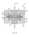
- Figure 4 shows the mould schematically, generally indicated 101.
- the mould 101 comprises two plates 300 and 400 which, in operative conditions, are coupled in a leaktight manner to define a moulding cavity 500.
- Two opposed pistons 600 and 700 are mounted inside the moulding cavity 500 and are slidable along a common axis X-X. These pistons 600 and 700 are constructed in a manner such as to form a seal against the internal walls of the moulding cavity 500.
- the mould 101 has support means 800 for supporting the core 200, such as that produced by the process described above, between the two pistons 600, 700.
- These support means 800 are preferably resilient means and, even more preferably, are springs.
- a layer 900 of a mixture in the solid state is deposited in the moulding cavity 500.
- the layer 900 is deposited on the surface 701 of the piston 700 which faces the piston 600 of the plate 300.
- the core 200 is then positioned on the layer 900 so as to cover it and, at the same time, in a manner such as to be kept suspended and not to sink into the mixture.
- This suspension is achieved by means of the above-mentioned support means 800.
- a further layer 901 of the above-mentioned mixture is deposited on the core to produce a layered structure.
- the mould 101 can be closed so that the lower surface 601 of the piston 600 comes into contact with the layer 901.
- the cover can now be moulded by suitable heating and by a pressure exerted by the pistons 600 and 700 on the layers of mixture 900 and 901.
- the mixture comprising the carbon-based fibres is heated in the mould to a temperature of from 80°C to 180°C, preferably 100-120°C, and a pressure of between 0.1 N/cm 2 and 5 N/cm 2 , preferably 0,5-1 N/cm 2 is applied thereto.
- a semi-finished product having a "sandwich” structure is produced and is removed from the mould and subjected to a first firing in a furnace at a temperature such as to bring about carbonization or pyrolysis of the resin.
- This firing is performed in a conventional furnace at a temperature which depends substantially on the type of binder used and which is generally within the range of 900 - 1200°C.
- the firing is performed in the presence of a flow of inert gas such as nitrogen or argon and under a plenum pressure of 10-100 mbars, preferably 20 - 30 mbars.
- inert gas such as nitrogen or argon
- This flow also advantageously removes the gases which are liberated by the pyrolysis of the organic binder.
- the semi-finished product acquires a greater porosity, which is important during the subsequent firing since it allows the fused silicon to infiltrate into the semi-finished product.
- the process may further comprise a step for the finishing of the surface of the semi-finished product coming from the first firing.
- the finishing step is preferably performed dry, for example, by diamonds, since the semi-finished product which, after the first firing, has acquired a predetermined porosity, might disadvantageously absorb liquid substances if the finishing were performed wet.
- the fired semi-finished product is then subjected to a second firing in the presence of silicon at a temperature such as to bring about fusion of the silicon and its infiltration into the pores of the semi-finished product.
- the infiltration of the silicon increases the cohesion of the bundles of carbon filaments whilst, at the same time, the fused silicon reacts partially with the carbon of the semi-finished product in the conditions of the second firing, forming silicon carbides which have the effect of improving the cohesion characteristics of the material.
- the semi-finished product In order to perform the second firing, the semi-finished product, fired and possibly subjected to finishing, is inserted in the chamber of a container of a volume such that it can hold the semi-finished product together with the necessary quantity of silicon, the space formed between the semi-finished product and the container being filled with silicon which surrounds the semi-finished product.
- the quantity of silicon used is therefore that required to fill the porosity of the semi-finished product, or a slightly greater quantity.
- the above-mentioned space is filled with pure silicon or with an alloy of silicon and aluminium or copper, in granular or powder form.
- the chamber may be in communication with the exterior by means of suitable holes which allow gases liberated during the firing to escape.
- the container is inserted in a suitable, conventional furnace, heated to a temperature of 1400-1700°C.
- the silicon melts and infiltrates the pores of the semi-finished product (silication).
- the firing is performed under reduced pressure, the pressure being reduced by from 900 mbars to 300 mbars, preferably by from 800 to 500 mbars.
- the core and/or the cover is cooled, for example, with argon or, preferably, with nitrogen, so that the residual silicon solidifies in small spheres which can easily be recovered from the container.
- the core and/or the cover according to the invention may be subjected to finishing operations, for example, surface finishing, which may be performed dry or wet, in conventional manner.
- furnace firing steps that is, the pyrolysis and silication steps, could take place in a single furnace, reducing production times and the complexity of the apparatus.
- a braking band which has optimal characteristics of compactness can thus be produced easily and inexpensively.
- braking bands constructed with the materials set out above may give rise to cracks or fractures as a result of thermal and/or compression stresses to which a braking band is subject during use. These cracks or fractures tend to be propagated rapidly throughout the structure of a braking band and may cause it to disintegrate completely.
- a plurality of reinforcing fibres may advantageously be introduced into the mixture for the moulding of the above-described core and/or of the covers, so as to hinder the propagation of cracks.
- the reinforcing fibres preferably extend concentrically and/or radially in the structure of the braking band according to the invention, throughout its shape.
- the reinforcing fibres may be provided only in some regions of the braking band, in accordance with the regions in which cracks or their propagation paths arise, both of which can be predicted on the basis of structural calculations.
- the crack-propagation paths are more likely to be arranged radially and are propagated outwardly from the interior to bring about explosion of the braking band.
- reinforcing fibres have satisfactory characteristics of cohesion with the other components of the mixture of the braking band according to the invention to prevent the entire structure from disintegrating during use, even in the absence of cracks or fractures.
- the reinforcing fibres must be substantially inert with regard to the components of the mixture and sufficiently able to withstand the pyrolysis and silicon-infiltration temperatures, to avoid their degradation during the preparation of the braking band according to the invention.
- the material of the reinforcing fibres is preferably constituted by carbon fibres. It is, however, possible to use other materials such as SiC, Si 3 N 4 , or TiC, as well as metallic materials, for example, platinum, which can withstand the temperatures of the interaction with silicon.
- the reinforcing fibres may be incorporated in the core and/or in the cover of the braking band according to the invention in various ways.
- the reinforcing fibres may be arranged in a plurality of bundles which are arranged in predefined directions.
- These directions may be warp and weft directions, the bundles forming a fabric.
- the fabric may comprise from 2 to 30 fibres per cm, preferably 5-8 fibres/cm.
- a preformed fabric may advantageously be inserted directly in the mixture.
- the reinforcing fibres may constitute a non-woven fabric, for example, a felt.
- the reinforcing fibres may also be arranged in layers both in the core and in the cover or in only one of these two.
- the reinforcing fibres are constituted by a fabric or by a non-woven fabric, they are bi-directional and can therefore be arranged so as to be either coplanar with or perpendicular to the plane in which the braking band lies.
- the contents of the components of the mixture used to form the core and/or the cover according to the invention may vary as percentages by volume relative to the volume of the material as follows:
- the bundles of filaments may have diameters of from 0.1 to 2 mm, preferably from 0.3 to 0.5 mmm.
- the content of bundles of filaments in the mixture may vary from 50 to 80% by volume relative to the volume of the mixture and is preferably within the range of 60-70%.
- the bundles of filaments and/or the reinforcing fibres may be advantageously coated beforehand with a protective resin, preferably polyurethane, before being used in accordance with the process of the invention.
- a protective resin preferably polyurethane
- the bundles of filaments and the reinforcing fibres may be coated beforehand with the same organic binder which is used for the preparation of the mixture.
- the resin and the organic binder carbonize, creating a protective layer on the bundles of filaments and on the reinforcing fibres, preventing any disintegration or even dissolving thereof during the subsequent treatment with silicon.
- the bundles of filaments and the reinforcing fibres therefore retain their original shapes throughout the process, thus producing a product with good characteristics of cohesion and strength.
- the organic binder is a conventional binder which may be selected from the group comprising phenolic and acrylic resins, paraffin, pitches, polystyrenes, etc.
- the binder is preferably selected from the group comprising pitches and phenolic resins.
- the binder may be added to the mixture in any desired form, for example in the solid, semi-liquid, or liquid state, or in solution.
- phenolic resin may be added in the form of pellets, powder, or granules.
- the content of organic binder in the mixture may vary from 5% to 30% by volume relative to the volume of the mixture and is preferably within the range of 20% - 26%.
- the mixture may also contain other conventional additives used as fillers and, indirectly, for regulating the porosity and the density of the desired composite material.
- additives are constituted by particles of inorganic materials such as, preferably, graphite, silicon carbide, or metal carbide or nitride powders.
- the content of additives in the mixture may vary from 0.7% to 23% by volume relative to the volume of the mixture and is preferably within the range of 9% - 15%.
- the mixing may be performed in conventional manner and with conventional apparatus and the bundles of filaments are arranged randomly in various directions.
- the reinforcing fibres may be incorporated in the mixture in various ways.
- this incorporation is performed by the following steps:
- the above-described layering steps may be repeated a predetermined number of times so as to produce a multi-layer core and/or cover in which each layer of reinforcing fibres is incorporated between two layers of mixture comprising bundles of filaments.
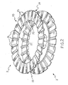
- Figure 2 shows two complementary half-cores 2 produced in accordance with the above-described process for the moulding of a core.
- the half-cores 2 are annular in shape and each has an outer face 20, an inner face 21, an outer peripheral edge 22, and an inner peripheral edge 23.
- Grooves 24 extend through the outer face 20 and, preferably, are arranged radially, are spaced apart uniformly by flat portions 25, and extend through the outer face 20 from the outer peripheral edge 22 to the inner peripheral edge 23 of the half-core 2.
- the inner face 21 also has grooves 26 formed in the region of the flat portions 25.
- the circumferential extent of the grooves 26 is greater than that of the corresponding grooves 24 and, moreover, the grooves 26 open in the outer peripheral edge 22, but terminate against a closure wall 27 in the region of the inner peripheral edge 23.
- each groove 26 of each of the two half-cores 2 forms a channel which is connected to a corresponding channel in order to close the venting passage or duct 28.
- venting passages 28 are thus open at the outer peripheral edge 22, but are closed by the walls 27 at the inner peripheral edge 23 of each of the two half-cores 2.
- FIG. 5 shows a braking band 10 comprising the core 200 and two covers 8 arranged so as to produce a "sandwich" structure.
- the braking band 10 has an outer peripheral edge 11 having openings 12 corresponding to the venting passages 28 described above, and an inner peripheral edge 13 provided with seats 14 which extend for a predetermined distance towards the outer peripheral edge 11.
- these seats 14 are such as to house corresponding teeth of a brake disk bell (not shown).
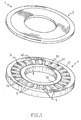
- Figure 1 shows schematically a mould 1 for moulding a half-core, in which two plates 3 and 4 are disposed facing one another. Once these plates 3 and 4 have been brought into contact, they define an internal cavity which constitutes the moulding cavity of the mould 1.
- the plate 4 is in the form of a ring 41 defining a central opening 40.
- the ring 41 has a central cavity 5 which, with a corresponding cavity provided in the plate 3, defines the cavity for moulding the core.
- the central cavity 5 is formed by a base 50, an outer side wall 51 and an inner side wall 52.
- the outer side wall 51 is positioned in the vicinity of the periphery of the mould 1 and the inner side wall 52 is positioned in the vicinity of the central opening 40 of the mould 1.
- the central cavity 5 has projections 6 spaced apart by grooves 7.
- the projections 6 are intended to form the surfaces of the venting passages of the braking band of the invention.
- the grooves 7, on the other hand, will form the points of interruption between the passages.
- the projections 7 extend radially from the outer side wall 51 of the central cavity 5 towards the inner side wall 52 of the central cavity 5. These projections preferably terminate a predetermined distance form the inner side wall 52 so as to define a form of circular channel 53 in the central cavity 5.
- each half-core 2 is formed by means of the particular channel 53.
- the half-cores described above may have different shapes.
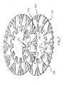
- Figure 7 shows two identical facing half-cores 220.
- the half-cores 220 are also annular and each has an outer face 221, an inner face 222, an outer peripheral edge 223, and an inner peripheral edge 224.
- Grooves 225 extend though the inner face 222 from the outer peripheral edge 223, groups of three grooves 225 converging into a single groove 226 which opens in the inner peripheral edge 224.
- the inner peripheral edge 224 has seats 227 which extend towards the outer peripheral edge 223 between adjacent grooves 226.
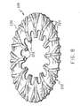
- the two half-cores 220 have been fitted together to form a core 228 of a braking band according to the present invention. As can be seen, the two half-cores 220 have been fixed together with the two respective complementary inner faces 222 cooperating to form the venting passages 229 of a braking band.
- each of the two half-cores 220 constitute channels which are fitted together to define the venting passages 229.
- venting passages 229 are thus open both at the outer peripheral edge 223 and at the inner peripheral edge 224 of the half-cores 220.
- Two covers 230 are moulded directly onto the core 228, as described above with reference to the braking band 10 of Figure 5.
- the core 228 is thus enclosed like a "sandwich" between the two covers 230 so as to form a braking band 240 ( Figure 9).
- the seats 227 described above correspond to the seats 14 of the braking band 10 and, in the same manner as the latter, are intended to be coupled with corresponding teeth of a brake disk bell (not shown).
- the above-described step of the moulding of the half-cores may be performed by adapting the mould used for the production of the half-cores 2 of Figure 2.
- Figure 6 shows schematically a mould 111 for the production of the half-cores 220. It is clear that the moulding cavity of the mould constitutes precisely an impression of the half-cores 220 and it will not therefore be described in detail.
- the advantage provided by the particular shape of the core 228 lies in the fact that, as well as increasing the heat-exchange surface, it also permits an air-flow through the band, improving its heat-dissipation efficiency.
- the braking band according to the invention can be produced with the aid of conventional techniques used for the production of the corresponding known braking bands and, moreover, the quantity of reinforcing fibres added to the material is relatively low (no greater than 30% by volume).
- the particular use of the resilient means 800 provides a suitable support for the core and at the same time achieves optimal balancing of the pressures exerted by the two pistons 600 and 700 during the moulding of the covers.
- the braking band according to the invention is distinguished by its optimal friction characteristics, its hardness, bending strength, resistance to wear and to heat generated by friction, and impact and compression strength.
- the present invention is thus realized by the implementation of a simple and inexpensive process which also produces a braking band with the appropriate safety characteristics from the structural point of view and from the point of view of easy production.
Landscapes
- Chemical & Material Sciences (AREA)
- Engineering & Computer Science (AREA)
- Ceramic Engineering (AREA)
- Manufacturing & Machinery (AREA)
- Materials Engineering (AREA)
- Structural Engineering (AREA)
- Organic Chemistry (AREA)
- Chemical Kinetics & Catalysis (AREA)
- Inorganic Chemistry (AREA)
- General Engineering & Computer Science (AREA)
- Mechanical Engineering (AREA)
- Composite Materials (AREA)
- Braking Arrangements (AREA)
Abstract
Description
- The present invention relates to a process for the production of a braking band for a brake disk with venting passages, and a braking band produced by the process.
- In particular, the present invention relates to a process for the production of a braking band which has venting passages and is made of a ceramic material such as, for example C/SiC.
- In general, braking bands with venting passages which are currently available on the market are produced by two different processes.
- The first process provides for the moulding of the braking band as a solid body and for the subsequent formation of radial and non-radial holes lying in a central plane of the thickness of the band and thus constituting the venting passages.
- The second process provides for a first step for the moulding of two reflectively symmetrical portions of the braking band having grooves in their facing surfaces. The two portions are then brought into contact and glued to form the finished product in which each groove of each of the portions represents one half of a venting duct.
- However, the above-mentioned solutions have some disadvantages.
- In the first process, the formation of the holes in the thickness of the braking bands is undoubtedly very difficult because of the hardness of the materials which have to be used in production.
- The second process, on the other hand, has the great disadvantage that it is necessary to glue two portions of a braking band which, since they are formed separately, may not correspond and may therefore fit together incorrectly. This could give rise to a product which might easily be subject to dangerous detachment of these two portions.
- Further it is known from DE-A-4 438 456 that a separately moulded core and friction bodies of a carbon friction unit can be joined by infiltration with molten Si. DE-A-19 834 571 discloses a mould containing a cavity between two punches, a floating die and an anular insert.
- As a result, there is a need to provide a process for the production of braking bands with venting passages which is particularly easy to implement and effective, as well as braking bands produced by the process.
- The problem upon which the present invention is based is therefore to devise a process for the production of braking bands which has characteristics such as to satisfy the above-mentioned requirements and at the same time to overcome the disadvantages of the processes of the prior art.
- This problem is solved by a process for the production of a braking band having venting passages, comprising the following steps:
- moulding a core of the braking band in a suitable mould,
- moulding two covers onto the core in a further suitable mould so as to form a semi-finished product having a "sandwich" structure,
- firing the semi-finished product so as to produce a predetermined porosity of the covers,
- firing the semi-finished product further, in the presence of silicon, at a temperature such as substantially to bring about fusion of the silicon and its infiltration into the covers.
- Further characteristics and the advantages of the process for the production of braking bands, as well as the braking bands produced by the process according to the present invention, will become clear from the following description of some preferred embodiments thereof, given by way of non-limiting example with reference to the appended drawings, in which:
- Figure 1 is a schematic perspective view of an open mould for the production of a half-core of a braking band according to the invention,
- Figure 2 is a perspective view of two facing half-cores produced with the mould of Figure 1,
- Figure 3 is a perspective view of a core of a braking band produced by the joining-together of the two half-cores of Figure 2,
- Figure 4 shows, in section, a mould during the operative step for the moulding of a cover of a braking band according to the invention,
- Figure 5 is a perspective view of a braking band according to the invention,
- Figure 6 is a schematic perspective view of an open mould for the production of a half-core of a braking band according to a variant of the invention,
- Figure 7 is a perspective view of two facing half-cores produced with the mould of Figure 6,
- Figure 8 is a perspective view of a core of a braking band produced by joining together the two half-cores of Figure 7, and
- Figure 9 is a perspective view of a braking band according to a variant of the invention.
-
- The process according to the present invention provides for the moulding of a core in which venting passages are defined and for the subsequent moulding of two covers onto the core so as to produce a semi-finished product with a "sandwich" structure.
- With reference to Figures 1 to 5, the core is advantageously produced by a process which provides, first of all, for the moulding of two half-cores in which grooves of the venting passages are defined and, subsequently, for the joining-together of the half-cores to produce the core.
- In detail, the process provides for the steps of:
- a) providing a suitable mould,
- b) preparing a mixture comprising a predetermined quantity of fibres and/or filaments constituted substantially by carbon, and a predetermined quantity of an organic binder,
- c) depositing the mixture in the suitable mould,
- d) moulding a first half-core in the mould,
- e) moulding a second half-core by repeating steps a) to d),
- f) fixing the first and second half-cores together to produce the core in which venting passages are defined.
-
- The mixture for moulding the half-cores preferably comprises fibres and/or filaments of carbon-based materials selected from the group consisting of wood and products of the processing of wood, vegetable fibres, thermosetting resins, and products produced by pyrolysis of substances of synthetic origin such as, for example, polyacrylonitrile (PAN) and polysilazane.
- In particular, these materials comprise sawdust or chippings and the like, hemp, and similar textile fibres. Moreover, the filaments derived from these materials are variable from 3000 to 50000 units and have diameters of between 2 and 3 µm. These filaments may also be chopped to lengths of less than 30 mm.
- These materials are mixed with an aggregating resin such as, for example, polyurethane or, more preferably, a phenolic resin, pitches, and other additives.
- Once prepared, this mixture is deposited in the moulding cavity of the mould and subjected to heating to temperatures generally of between 80°C and 180°C, and to compression to produce a half-core.
- A further half-core is produced by repeating precisely the same process as described above.
- The two half-cores thus produced are then juxtaposed so as to fit the grooves of the venting passages together and are fixed to one another as shown schematically in Figures 2 and 3, preferably by gluing with a liquid thermosetting resin. More preferably, the resin is a phenolic resin.
- If the gluing takes place when the two half-cores are still hot, that is, when they have just come out of the mould, the gluing resin advantageously sets immediately. There is consequently no need for further heating processes to bring about setting of the resin.
- The next step of the process for the production of a braking band according to the present invention requires the provision of a further mould in which the core previously produced is inserted in order for two covers to be moulded around the core.
- This step of the moulding of the covers will now be described with reference to Figures 4 and 5. The term "cover" is intended to define the outer portion of the braking band which covers the core of the band and therefore constitutes the braking surface which is acted on, for example, by the pads of a disk brake.
- Figure 4 shows the mould schematically, generally indicated 101.
- The
mould 101 comprises twoplates moulding cavity 500. - Two
opposed pistons moulding cavity 500 and are slidable along a common axis X-X. Thesepistons moulding cavity 500. - In particular, the
mould 101 has support means 800 for supporting thecore 200, such as that produced by the process described above, between the twopistons - These support means 800 are preferably resilient means and, even more preferably, are springs.
- The step of the moulding of the cover with the use of the above-mentioned cover-moulding mould will be described below with reference to Figure 4.
- First of all, when the
mould 101 is in the open configuration (not shown), that is, when the twoplates respective pistons layer 900 of a mixture in the solid state, identical to the mixture described above with reference to the moulding of the core, is deposited in themoulding cavity 500. In particular, thelayer 900 is deposited on thesurface 701 of thepiston 700 which faces thepiston 600 of theplate 300. - The
core 200 is then positioned on thelayer 900 so as to cover it and, at the same time, in a manner such as to be kept suspended and not to sink into the mixture. This suspension is achieved by means of the above-mentioned support means 800. - After the core has been positioned inside the
moulding cavity 500, afurther layer 901 of the above-mentioned mixture is deposited on the core to produce a layered structure. - At this point, the
mould 101 can be closed so that thelower surface 601 of thepiston 600 comes into contact with thelayer 901. - The cover can now be moulded by suitable heating and by a pressure exerted by the
pistons mixture - During the steps for the moulding both of the half-cores and of the covers according to the process of the invention, the mixture comprising the carbon-based fibres is heated in the mould to a temperature of from 80°C to 180°C, preferably 100-120°C, and a pressure of between 0.1 N/cm2 and 5 N/cm2, preferably 0,5-1 N/cm2 is applied thereto.
- Upon completion of the moulding, a semi-finished product having a "sandwich" structure is produced and is removed from the mould and subjected to a first firing in a furnace at a temperature such as to bring about carbonization or pyrolysis of the resin.
- This firing is performed in a conventional furnace at a temperature which depends substantially on the type of binder used and which is generally within the range of 900 - 1200°C.
- The firing is performed in the presence of a flow of inert gas such as nitrogen or argon and under a plenum pressure of 10-100 mbars, preferably 20 - 30 mbars.
- This flow also advantageously removes the gases which are liberated by the pyrolysis of the organic binder.
- During this step of the process, the semi-finished product acquires a greater porosity, which is important during the subsequent firing since it allows the fused silicon to infiltrate into the semi-finished product.
- According to one embodiment of the invention, the process may further comprise a step for the finishing of the surface of the semi-finished product coming from the first firing.
- This advantageously enables any surface deformations of the semi-finished product to be removed by conventional apparatus so as to give it the desired shape.
- The finishing step is preferably performed dry, for example, by diamonds, since the semi-finished product which, after the first firing, has acquired a predetermined porosity, might disadvantageously absorb liquid substances if the finishing were performed wet.
- The fired semi-finished product is then subjected to a second firing in the presence of silicon at a temperature such as to bring about fusion of the silicon and its infiltration into the pores of the semi-finished product.
- As stated above, the infiltration of the silicon increases the cohesion of the bundles of carbon filaments whilst, at the same time, the fused silicon reacts partially with the carbon of the semi-finished product in the conditions of the second firing, forming silicon carbides which have the effect of improving the cohesion characteristics of the material.
- In order to perform the second firing, the semi-finished product, fired and possibly subjected to finishing, is inserted in the chamber of a container of a volume such that it can hold the semi-finished product together with the necessary quantity of silicon, the space formed between the semi-finished product and the container being filled with silicon which surrounds the semi-finished product. The quantity of silicon used is therefore that required to fill the porosity of the semi-finished product, or a slightly greater quantity.
- The above-mentioned space is filled with pure silicon or with an alloy of silicon and aluminium or copper, in granular or powder form.
- The chamber may be in communication with the exterior by means of suitable holes which allow gases liberated during the firing to escape.
- After the silicon has been loaded, the container is inserted in a suitable, conventional furnace, heated to a temperature of 1400-1700°C.
- At the above-mentioned temperatures, the silicon melts and infiltrates the pores of the semi-finished product (silication).
- The firing is performed under reduced pressure, the pressure being reduced by from 900 mbars to 300 mbars, preferably by from 800 to 500 mbars.
- Upon completion of the firing, the core and/or the cover is cooled, for example, with argon or, preferably, with nitrogen, so that the residual silicon solidifies in small spheres which can easily be recovered from the container.
- The core and/or the cover according to the invention, thus obtained, may be subjected to finishing operations, for example, surface finishing, which may be performed dry or wet, in conventional manner.
- Clearly, the furnace firing steps, that is, the pyrolysis and silication steps, could take place in a single furnace, reducing production times and the complexity of the apparatus.
- With the process for the moulding of a braking band according to the present invention, a braking band which has optimal characteristics of compactness can thus be produced easily and inexpensively.
- Moreover, it is known that, in some cases, braking bands constructed with the materials set out above may give rise to cracks or fractures as a result of thermal and/or compression stresses to which a braking band is subject during use. These cracks or fractures tend to be propagated rapidly throughout the structure of a braking band and may cause it to disintegrate completely.
- A plurality of reinforcing fibres may advantageously be introduced into the mixture for the moulding of the above-described core and/or of the covers, so as to hinder the propagation of cracks.
- The reinforcing fibres preferably extend concentrically and/or radially in the structure of the braking band according to the invention, throughout its shape.
- Alternatively, the reinforcing fibres may be provided only in some regions of the braking band, in accordance with the regions in which cracks or their propagation paths arise, both of which can be predicted on the basis of structural calculations.
- For example, the crack-propagation paths are more likely to be arranged radially and are propagated outwardly from the interior to bring about explosion of the braking band.
- The propagation of the cracks in a braking band is therefore hindered by arranging the reinforcing fibres along concentric annular portions of the band.
- It is important that the reinforcing fibres have satisfactory characteristics of cohesion with the other components of the mixture of the braking band according to the invention to prevent the entire structure from disintegrating during use, even in the absence of cracks or fractures.
- Moreover, the reinforcing fibres must be substantially inert with regard to the components of the mixture and sufficiently able to withstand the pyrolysis and silicon-infiltration temperatures, to avoid their degradation during the preparation of the braking band according to the invention.
- For this purpose, the material of the reinforcing fibres is preferably constituted by carbon fibres. It is, however, possible to use other materials such as SiC, Si3N4, or TiC, as well as metallic materials, for example, platinum, which can withstand the temperatures of the interaction with silicon.
- The reinforcing fibres may be incorporated in the core and/or in the cover of the braking band according to the invention in various ways. For example, the reinforcing fibres may be arranged in a plurality of bundles which are arranged in predefined directions.
- These directions may be warp and weft directions, the bundles forming a fabric.
- Alternatively, several combined or intertwined bundles of reinforcing fibres form a single warp or weft thread to constitute the fabric.
- The fabric may comprise from 2 to 30 fibres per cm, preferably 5-8 fibres/cm.
- Instead of arranging the fibres in the mixture so as to form a fabric as defined herein, a preformed fabric may advantageously be inserted directly in the mixture.
- Alternatively, the reinforcing fibres may constitute a non-woven fabric, for example, a felt.
- The reinforcing fibres may also be arranged in layers both in the core and in the cover or in only one of these two.
- When the reinforcing fibres are constituted by a fabric or by a non-woven fabric, they are bi-directional and can therefore be arranged so as to be either coplanar with or perpendicular to the plane in which the braking band lies.
- The contents of the components of the mixture used to form the core and/or the cover according to the invention may vary as percentages by volume relative to the volume of the material as follows:
- bundles of filaments 40-70%, preferably 50-60%;
- binder 5-30%, preferably 15-25%;
- additives 0.5-20%, preferably 1-15%;
- reinforcing fibres 4-30%, preferably 10-20%.
-
- In the process according to the invention, the bundles of filaments may have diameters of from 0.1 to 2 mm, preferably from 0.3 to 0.5 mmm.
- It should be noted in particular that, in the absence of the reinforcing fibres, the content of bundles of filaments in the mixture may vary from 50 to 80% by volume relative to the volume of the mixture and is preferably within the range of 60-70%.
- The bundles of filaments and/or the reinforcing fibres may be advantageously coated beforehand with a protective resin, preferably polyurethane, before being used in accordance with the process of the invention.
- Alternatively, the bundles of filaments and the reinforcing fibres may be coated beforehand with the same organic binder which is used for the preparation of the mixture.
- Greater cohesion of the material and a more compact product are thus obtained.
- During the first firing of the semi-finished product, the resin and the organic binder carbonize, creating a protective layer on the bundles of filaments and on the reinforcing fibres, preventing any disintegration or even dissolving thereof during the subsequent treatment with silicon.
- The bundles of filaments and the reinforcing fibres therefore retain their original shapes throughout the process, thus producing a product with good characteristics of cohesion and strength.
- The organic binder is a conventional binder which may be selected from the group comprising phenolic and acrylic resins, paraffin, pitches, polystyrenes, etc.
- The binder is preferably selected from the group comprising pitches and phenolic resins.
- The binder may be added to the mixture in any desired form, for example in the solid, semi-liquid, or liquid state, or in solution.
- For example, phenolic resin may be added in the form of pellets, powder, or granules.
- The content of organic binder in the mixture may vary from 5% to 30% by volume relative to the volume of the mixture and is preferably within the range of 20% - 26%.
- The mixture may also contain other conventional additives used as fillers and, indirectly, for regulating the porosity and the density of the desired composite material.
- These additives are constituted by particles of inorganic materials such as, preferably, graphite, silicon carbide, or metal carbide or nitride powders.
- The content of additives in the mixture may vary from 0.7% to 23% by volume relative to the volume of the mixture and is preferably within the range of 9% - 15%.
- The mixing may be performed in conventional manner and with conventional apparatus and the bundles of filaments are arranged randomly in various directions.
- The reinforcing fibres may be incorporated in the mixture in various ways.
- According to a preferred method of implementing the process according to the invention, this incorporation is performed by the following steps:
- i) placing a first layer of the mixture in the moulding cavity of the mould for the core and/or for the cover,
- ii) adding, to the first layer of mixture, the plurality of reinforcing fibres which extend along the shape in a manner such as to hinder the propagation of cracks, and
- iii) placing a second layer of the mixture on the first layer so as to incorporate the plurality of reinforcing fibres completely in the mixture.
-
- Clearly, the above-described layering steps may be repeated a predetermined number of times so as to produce a multi-layer core and/or cover in which each layer of reinforcing fibres is incorporated between two layers of mixture comprising bundles of filaments.
- Figure 2 shows two complementary half-
cores 2 produced in accordance with the above-described process for the moulding of a core. - In particular, the half-
cores 2 are annular in shape and each has anouter face 20, aninner face 21, an outerperipheral edge 22, and an innerperipheral edge 23. -
Grooves 24 extend through theouter face 20 and, preferably, are arranged radially, are spaced apart uniformly byflat portions 25, and extend through theouter face 20 from the outerperipheral edge 22 to the innerperipheral edge 23 of the half-core 2. - The
inner face 21 also hasgrooves 26 formed in the region of theflat portions 25. - In particular, the circumferential extent of the
grooves 26 is greater than that of thecorresponding grooves 24 and, moreover, thegrooves 26 open in the outerperipheral edge 22, but terminate against aclosure wall 27 in the region of the innerperipheral edge 23. - In Figure 3, two half-
cores 2 have been fitted together to form acore 200 of a braking band according to the present invention. As can be seen, the half-cores 2 have been fixed together with the two respective complementary inner faces 21 cooperating to form ventingpassages 28 of a braking band. - In other words, each
groove 26 of each of the two half-cores 2 forms a channel which is connected to a corresponding channel in order to close the venting passage orduct 28. - The venting
passages 28 are thus open at the outerperipheral edge 22, but are closed by thewalls 27 at the innerperipheral edge 23 of each of the two half-cores 2. - As already described fully above, two covers 8 are moulded directly onto the
core 200 and, in particular, onto the respective outer faces 20 of the half-cores 2.
Figure 5 shows abraking band 10 comprising thecore 200 and two covers 8 arranged so as to produce a "sandwich" structure. - Moreover, the
braking band 10 has an outer peripheral edge 11 havingopenings 12 corresponding to theventing passages 28 described above, and an innerperipheral edge 13 provided with seats 14 which extend for a predetermined distance towards the outer peripheral edge 11. - In particular, these seats 14 are such as to house corresponding teeth of a brake disk bell (not shown).
- The above-described step of the moulding of the half-cores may be performed with a suitable mould which will now be described below.
- Figure 1 shows schematically a mould 1 for moulding a half-core, in which two plates 3 and 4 are disposed facing one another. Once these plates 3 and 4 have been brought into contact, they define an internal cavity which constitutes the moulding cavity of the mould 1.
- Only one of the two plates, that is, the plate 4, will now be described, since the other plate is substantially complementary.
- The plate 4 is in the form of a
ring 41 defining acentral opening 40. Thering 41 has acentral cavity 5 which, with a corresponding cavity provided in the plate 3, defines the cavity for moulding the core. - The
central cavity 5 is formed by abase 50, anouter side wall 51 and aninner side wall 52. Theouter side wall 51 is positioned in the vicinity of the periphery of the mould 1 and theinner side wall 52 is positioned in the vicinity of thecentral opening 40 of the mould 1. - Moreover, the
central cavity 5 has projections 6 spaced apart bygrooves 7. The projections 6 are intended to form the surfaces of the venting passages of the braking band of the invention. Thegrooves 7, on the other hand, will form the points of interruption between the passages. - In particular, the
projections 7 extend radially from theouter side wall 51 of thecentral cavity 5 towards theinner side wall 52 of thecentral cavity 5. These projections preferably terminate a predetermined distance form theinner side wall 52 so as to define a form ofcircular channel 53 in thecentral cavity 5. - It should be noted that the
wall 27 of each half-core 2 is formed by means of theparticular channel 53. - According to a variant of the present invention and with reference to Figures 7, 8 and 9, the half-cores described above may have different shapes.
- In particular, Figure 7 shows two identical facing half-
cores 220. The half-cores 220 are also annular and each has anouter face 221, aninner face 222, an outerperipheral edge 223, and an inner peripheral edge 224. -
Grooves 225 extend though theinner face 222 from the outerperipheral edge 223, groups of threegrooves 225 converging into asingle groove 226 which opens in the inner peripheral edge 224. - Moreover, the inner peripheral edge 224 has
seats 227 which extend towards the outerperipheral edge 223 betweenadjacent grooves 226. - In Figure 8, the two half-
cores 220 have been fitted together to form acore 228 of a braking band according to the present invention. As can be seen, the two half-cores 220 have been fixed together with the two respective complementaryinner faces 222 cooperating to form the ventingpassages 229 of a braking band. - In particular, the
respective grooves cores 220 constitute channels which are fitted together to define the ventingpassages 229. - The venting
passages 229 are thus open both at the outerperipheral edge 223 and at the inner peripheral edge 224 of the half-cores 220. - Two covers 230 are moulded directly onto the
core 228, as described above with reference to thebraking band 10 of Figure 5. - The
core 228 is thus enclosed like a "sandwich" between the twocovers 230 so as to form a braking band 240 (Figure 9). - It should be noted that, in this embodiment of the invention, the
seats 227 described above correspond to the seats 14 of thebraking band 10 and, in the same manner as the latter, are intended to be coupled with corresponding teeth of a brake disk bell (not shown). - Moreover, the above-described step of the moulding of the half-cores may be performed by adapting the mould used for the production of the half-
cores 2 of Figure 2. - Figure 6 shows schematically a mould 111 for the production of the half-
cores 220. It is clear that the moulding cavity of the mould constitutes precisely an impression of the half-cores 220 and it will not therefore be described in detail. - The advantage provided by the particular shape of the core 228 lies in the fact that, as well as increasing the heat-exchange surface, it also permits an air-flow through the band, improving its heat-dissipation efficiency.
- The advantage of the process for the production of a braking band according to the invention is that can be implemented easily and inexpensively. In fact, both the mould for moulding the core and the mould for moulding the cover are particularly simple, easy to produce and easy to use.
- Moreover, it should be noted that the braking band according to the invention can be produced with the aid of conventional techniques used for the production of the corresponding known braking bands and, moreover, the quantity of reinforcing fibres added to the material is relatively low (no greater than 30% by volume).
- In addition, the particular use of the
resilient means 800 provides a suitable support for the core and at the same time achieves optimal balancing of the pressures exerted by the twopistons - It is also clear that the braking band according to the invention is distinguished by its optimal friction characteristics, its hardness, bending strength, resistance to wear and to heat generated by friction, and impact and compression strength.
- In particular, it should be noted that the absence of an adhesive layer of any type between the covers and the core of the braking band produced in accordance with the invention both simplifies the entire structure of the band and produces a structure stronger than that of the prior art.
- The present invention is thus realized by the implementation of a simple and inexpensive process which also produces a braking band with the appropriate safety characteristics from the structural point of view and from the point of view of easy production.
Claims (22)
- A process for the production of a braking band (10; 240) having venting passages (12; 229), comprising the following steps:moulding a core (200; 228) of the braking band in a suitable mould (1; 111),moulding two covers (8; 230) onto the core in a further suitable mould (101) so as to form a semi-finished product having a "sandwich" structure,firing the semi-finished product so as to produce a predetermined porosity of the covers,firing the semi-finished product further, in the presence of silicon, at a temperature such as substantially to bring about fusion of the silicon and its infiltration into the covers.
- A process for the production of a braking band (10; 240) according to Claim 1, in which the step of moulding the core (200; 228) of the braking band comprises the moulding of two half-cores (2; 220) and the juxtaposition and fixing-together thereof to form the core with the venting passages (12; 229).
- A process for the production of a braking band (10; 400) according to Claim 2 in which the moulding of the half-cores comprises the steps of:a) providing a suitable mould (1; 111),b) preparing a mixture comprising a predetermined quantity of fibres and/or filaments constituted substantially by carbon, and a predetermined quantity of an organic binder,c) depositing the mixture in the suitable mould,d) moulding a first half-core (2; 220) in the mould,e) moulding a second half-core (2; 220) by repeating steps a) to d),f) fixing the juxtaposed first and second half-cores together to produce the core in which the venting passages (28; 229) are defined.
- A process for the production of a braking band according to any one of Claims 1 to 3 in which the mixture for the moulding of the core comprises filaments of carbon-based materials selected from the group consisting of wood and products of the processing of wood, vegetable fibres, and thermosetting resins.
- A process for the production of a braking band according to Claim 4 in which the materials are sawdust or chippings, hemp and the like, and liquid thermosetting phenolic resins.
- A process for the production of a braking band according to any one of Claims 3 to 5 in which the fixing takes place by gluing with a liquid thermosetting resin, the resin preferably being a phenolic resin.
- A process for the production of a braking band according to Claim 6 in which the gluing takes place when the first and second half-cores have just come out of the mould.
- A process for the production of a braking band according to any one of Claims 1 to 7 in which the step of moulding the covers (8; 230) comprises:providing a suitable mould (101),depositing a first layer of a mixture in the suitable mould, the mixture comprising a predetermined quantity of fibres and/or filaments constituted substantially by carbon, and a predetermined quantity of an organic binder,positioning and supporting the core (200; 228) in the mould so that it is in contact with the first layer of mixture,depositing a second layer of the mixture on the core,moulding the covers around the core so as to produce a "sandwich" structure.
- A process for the production of a braking band (10; 240) according to Claim 8 in which the core (200; 229) is supported in the mould so as to float on the first layer of mixture, by means of resilient elements (800), the elements preferably being springs.
- A process for the production of a braking band (10; 240) according to Claim 8 or Claim 9 in which the mixture for the moulding of the core and/or of the covers comprises reinforcing fibres of carbon or of metallic materials.
- A process for the production of a braking band according to Claim 10 in which the reinforcing fibres are SiC, Si3N4, TiC, or platinum fibres.
- A process for the production of a braking band according to Claim 10 in which the reinforcing fibres are combined with one another or intertwined in bundles which form a single warp or weft thread to constitute a fabric.
- A process for the production of a braking band according to Claim 10 in which the reinforcing fibres constitute a non-woven fabric, preferably a felt.
- A braking band (10; 240) with venting passages (12; 229) obtainable by the process according to any one of the preceding claims.
- A braking band (10; 240) according to Claim 14, comprising a core (200; 228) having the venting passages (12, 229) and two covers (8; 230) fixed directly to the core externally so as to form a "sandwich" structure.
- A braking band (10; 240) according to Claim 15 in which the core (200; 228) is fixed to the covers (8, 230) by pyrolytic treatment between the respective contact surfaces.
- A braking band (10; 240) according to Claim 15 or Claim 16 in which the venting passages (12; 229) extend through the core (200; 228) from an outer peripheral edge (22; 223) thereof to an inner peripheral edge (23; 224) thereof.
- A braking band (10) according to Claim 17 in which the venting passages (28) open in the outer peripheral edge (22) but are closed by a wall (27) in the region of the inner peripheral edge (23) of the core (200).
- A braking band (10; 240) according to any one of Claims 14 to 18 in which the venting passages (12; 229) are arranged substantially radially.
- A braking band (240) according to any one of Claims 17 to 19 in which groups of three passages (225) extend from the outer peripheral edge (223), each group of three passages (225) converging into a single passage (226) which opens in the inner peripheral edge (224) of the core.
- A mould (101) for the production of a braking band, comprising two plates (300, 400) defining a cavity (500) for the moulding of the braking band, two pistons (600, 700) mounted in an opposed manner in the cavity (500) and slidable along a common axis (X-X), and support means (800) for supporting a core (200) of the braking band.
- A mould (101) according to Claim 21 in which the support means (800) are resilient means, preferably springs.
Applications Claiming Priority (1)
| Application Number | Priority Date | Filing Date | Title |
|---|---|---|---|
| PCT/IT2000/000543 WO2002051771A1 (en) | 2000-12-22 | 2000-12-22 | Process for the production of a braking band with venting passages and braking band obtained with said process |
Publications (2)
| Publication Number | Publication Date |
|---|---|
| EP1276704A1 EP1276704A1 (en) | 2003-01-22 |
| EP1276704B1 true EP1276704B1 (en) | 2003-10-29 |
Family
ID=11133605
Family Applications (1)
| Application Number | Title | Priority Date | Filing Date |
|---|---|---|---|
| EP00987633A Expired - Lifetime EP1276704B1 (en) | 2000-12-22 | 2000-12-22 | Process for the production of a braking band with venting passages and braking band obtained with said process |
Country Status (6)
| Country | Link |
|---|---|
| US (1) | US6797094B2 (en) |
| EP (1) | EP1276704B1 (en) |
| JP (1) | JP2004516222A (en) |
| AT (1) | ATE253023T1 (en) |
| DE (1) | DE60006292T2 (en) |
| WO (1) | WO2002051771A1 (en) |
Families Citing this family (29)
| Publication number | Priority date | Publication date | Assignee | Title |
|---|---|---|---|---|
| WO2003056206A1 (en) * | 2001-12-21 | 2003-07-10 | Freni Brembo S.P.A. | A shaped composite material |
| DE10212486A1 (en) * | 2002-03-21 | 2003-10-16 | Sgl Carbon Ag | Composite with carbon reinforcing fibers |
| DE10229296A1 (en) * | 2002-06-29 | 2004-01-15 | Komage-Gellner Maschinenfabrik Kg | Device and method for producing a molded article |
| EP1576301B1 (en) * | 2002-12-24 | 2007-12-05 | Freni Brembo S.p.A. | Mould and method for the manufacture of a braking band of composite material with ventilation ducts and holes in the firction surfaces |
| US6997292B2 (en) * | 2003-01-17 | 2006-02-14 | Performance Friction Corporation | Brake rotor attachment assembly that promotes in plane uniform torque transfer distribution |
| UA84862C2 (en) * | 2003-03-03 | 2008-12-10 | Месье-Бугатти | Substrate |
| SE527376C2 (en) * | 2003-12-05 | 2006-02-21 | Haldex Brake Prod Ab | Brake disc |
| US8651247B2 (en) * | 2005-04-01 | 2014-02-18 | Performance Friction Corporation | Direct drive braking system including an integrated package bearing |
| US7294188B2 (en) * | 2005-12-20 | 2007-11-13 | Akebono Corporation (North America) | Mixing method for friction material with a pre-mix in a single mixer |
| US7543691B2 (en) * | 2006-07-12 | 2009-06-09 | Delphi Technologies, Inc. | Brake rotor assembly |
| WO2008007401A1 (en) | 2006-07-14 | 2008-01-17 | Brembo Ceramic Brake Systems S.P.A. | Braking band composite structure |
| US20080135359A1 (en) * | 2006-12-11 | 2008-06-12 | Basirico John T | Brake rotor with ceramic matrix composite friction surface plates |
| US8353392B2 (en) * | 2007-05-21 | 2013-01-15 | Sgl Carbon Se | Internally vented brake disk with improved heat dissipation |
| US20090084639A1 (en) * | 2007-10-01 | 2009-04-02 | James Colegrove | Bicycle brake system |
| KR101051408B1 (en) * | 2008-09-30 | 2011-07-22 | 주식회사 데크 | Manufacturing Method of Ceramic Brake Disc Rotor with Internal Cooling Channel |
| US20100206674A1 (en) * | 2009-02-16 | 2010-08-19 | Gm Global Technology Operations, Inc. | Disc Brake Rotors with Tilted Vane Geometry |
| CN103080592B (en) * | 2010-09-08 | 2015-07-22 | 三菱电机株式会社 | Braking apparatus, brake lining, method for manufacturing brake lining, and elevator system |
| KR101258828B1 (en) * | 2010-11-29 | 2013-05-06 | 주식회사 데크 | Carbon-ceramic brake disk and method for fabricating the same, and multifunctional core for being used in the same |
| US8813921B2 (en) * | 2011-11-24 | 2014-08-26 | Shimano Inc. | Bicycle disc brake rotor |
| US9234553B2 (en) * | 2011-12-29 | 2016-01-12 | Shimano Inc. | Bicycle brake disc |
| DE102013201303A1 (en) * | 2012-02-14 | 2013-08-14 | Continental Teves Ag & Co. Ohg | Internally ventilated automotive brake disc made of fiber composite material |
| USD803117S1 (en) * | 2014-08-05 | 2017-11-21 | Freni Brembo S.P.A. | Disc brake |
| USD789854S1 (en) * | 2015-12-22 | 2017-06-20 | Mahindra N.A. Tech Center | Disc brake rotor |
| US9856934B2 (en) | 2015-12-22 | 2018-01-02 | Mahindra N.A. Tech Center | Surface ventilated disc brake rotor |
| USD787996S1 (en) | 2016-04-29 | 2017-05-30 | Eaton Corporation | Clutch cover |
| EP3263935B1 (en) * | 2016-06-28 | 2019-09-11 | Adolf Kochsiek | Brake disk unit |
| DE102018115792A1 (en) * | 2018-06-29 | 2020-01-02 | Deutsches Zentrum für Luft- und Raumfahrt e.V. | Process for producing a green body and a ceramic component, green body and ceramic component |
| DE102019209499A1 (en) * | 2019-06-28 | 2020-12-31 | Brembo Sgl Carbon Ceramic Brakes Gmbh | Internally ventilated rotor |
| FR3145562A1 (en) * | 2023-02-03 | 2024-08-09 | Safran Ceramics | Preform for CVI densification with directed flow |
Family Cites Families (13)
| Publication number | Priority date | Publication date | Assignee | Title |
|---|---|---|---|---|
| US3895084A (en) * | 1972-03-28 | 1975-07-15 | Ducommun Inc | Fiber reinforced composite product |
| FR2478502A1 (en) * | 1980-03-19 | 1981-09-25 | Clesid Sa | PLATE LINGOTIERE FOR CONTINUOUS CASTING MACHINE |
| JPS62271718A (en) * | 1986-05-20 | 1987-11-26 | Nissei Plastics Ind Co | Mold |
| JP2931715B2 (en) * | 1992-05-12 | 1999-08-09 | 三菱電機株式会社 | Resin sealing method, resin sealing device, and gas spring |
| US5635226A (en) * | 1994-09-26 | 1997-06-03 | A.K. Technical Laboratory Inc. | Composite molding device for stretch blow molding |
| DE4438455C1 (en) * | 1994-10-28 | 1996-05-02 | Deutsche Forsch Luft Raumfahrt | Process for producing a friction unit by infiltration of a porous carbon body with liquid silicon |
| DE4438456C2 (en) * | 1994-10-28 | 2002-07-11 | Deutsch Zentr Luft & Raumfahrt | Friction unit |
| IT1294942B1 (en) * | 1997-08-01 | 1999-04-23 | Sacmi | PROCESS OF PRESSING CERAMIC POWDERS AND EQUIPMENT FOR IMPLEMENTING THE SAME. |
| DE19809720C2 (en) * | 1998-03-06 | 2001-02-15 | Krauss Maffei Kunststofftech | Dip edge tool for an injection molding machine |
| DE19834571C2 (en) * | 1998-07-31 | 2001-07-26 | Daimler Chrysler Ag | Process for the production of bodies from fiber-reinforced composite materials and use of the process |
| DE19921145B4 (en) * | 1999-05-07 | 2008-01-10 | Kobra Formen Gmbh | Vibrating drive for a mold |
| US6231329B1 (en) * | 1999-06-04 | 2001-05-15 | Milacron Inc. | Locking apparatus for a movable platen |
| US6572356B2 (en) * | 2001-01-08 | 2003-06-03 | Tooling Technology, Llc | Quick change tooling system for a thermoforming mold and the like |
-
2000
- 2000-12-22 WO PCT/IT2000/000543 patent/WO2002051771A1/en active IP Right Grant
- 2000-12-22 JP JP2002552874A patent/JP2004516222A/en active Pending
- 2000-12-22 EP EP00987633A patent/EP1276704B1/en not_active Expired - Lifetime
- 2000-12-22 AT AT00987633T patent/ATE253023T1/en not_active IP Right Cessation
- 2000-12-22 DE DE60006292T patent/DE60006292T2/en not_active Expired - Lifetime
- 2000-12-22 US US10/451,339 patent/US6797094B2/en not_active Expired - Lifetime
Also Published As
| Publication number | Publication date |
|---|---|
| ATE253023T1 (en) | 2003-11-15 |
| US6797094B2 (en) | 2004-09-28 |
| WO2002051771A1 (en) | 2002-07-04 |
| DE60006292D1 (en) | 2003-12-04 |
| DE60006292T2 (en) | 2004-08-26 |
| US20040035659A1 (en) | 2004-02-26 |
| EP1276704A1 (en) | 2003-01-22 |
| JP2004516222A (en) | 2004-06-03 |
Similar Documents
| Publication | Publication Date | Title |
|---|---|---|
| EP1276704B1 (en) | Process for the production of a braking band with venting passages and braking band obtained with said process | |
| US7134476B2 (en) | Process for the production of a braking band of a brake disk with ventilation ducts and a braking band produced by this process | |
| US7700181B2 (en) | Shaped composite material for breaking applications and a method for the preparation thereof | |
| EP2849942B1 (en) | Shaped composite material | |
| US20130306415A1 (en) | Disc for Disc Brakes | |
| EP1124071B2 (en) | Disk-brake disk | |
| EP1831129B1 (en) | A shaped composite material | |
| US20040126535A1 (en) | Process for producing hollow bodies comprising fiber-reinforced ceramic materials | |
| KR100694245B1 (en) | Method of manufacturing carbon fiber/ceramic brake disk | |
| EP1620657B1 (en) | Core assembly for a brake disk | |
| EP1456557A1 (en) | A shaped composite material | |
| KR101216144B1 (en) | Carbon-ceramic brake disc and method for manufacturing the same |
Legal Events
| Date | Code | Title | Description |
|---|---|---|---|
| PUAI | Public reference made under article 153(3) epc to a published international application that has entered the european phase |
Free format text: ORIGINAL CODE: 0009012 |
|
| AK | Designated contracting states |
Kind code of ref document: A1 Designated state(s): AT BE CH CY DE DK ES FI FR GB GR IE IT LI LU MC NL PT SE TR |
|
| AX | Request for extension of the european patent |
Free format text: AL;LT;LV;MK;RO;SI PAYMENT 20020304 |
|
| 17P | Request for examination filed |
Effective date: 20020304 |
|
| RAP1 | Party data changed (applicant data changed or rights of an application transferred) |
Owner name: FRENI BREMBO S.P.A. |
|
| GRAH | Despatch of communication of intention to grant a patent |
Free format text: ORIGINAL CODE: EPIDOS IGRA |
|
| GRAS | Grant fee paid |
Free format text: ORIGINAL CODE: EPIDOSNIGR3 |
|
| GRAA | (expected) grant |
Free format text: ORIGINAL CODE: 0009210 |
|
| AK | Designated contracting states |
Kind code of ref document: B1 Designated state(s): AT BE CH CY DE DK ES FI FR GB GR IE IT LI LU MC NL PT SE TR |
|
| AX | Request for extension of the european patent |
Extension state: AL LT LV MK RO SI |
|
| PG25 | Lapsed in a contracting state [announced via postgrant information from national office to epo] |
Ref country code: AT Free format text: LAPSE BECAUSE OF FAILURE TO SUBMIT A TRANSLATION OF THE DESCRIPTION OR TO PAY THE FEE WITHIN THE PRESCRIBED TIME-LIMIT Effective date: 20031029 Ref country code: FI Free format text: LAPSE BECAUSE OF FAILURE TO SUBMIT A TRANSLATION OF THE DESCRIPTION OR TO PAY THE FEE WITHIN THE PRESCRIBED TIME-LIMIT Effective date: 20031029 Ref country code: TR Free format text: LAPSE BECAUSE OF FAILURE TO SUBMIT A TRANSLATION OF THE DESCRIPTION OR TO PAY THE FEE WITHIN THE PRESCRIBED TIME-LIMIT Effective date: 20031029 Ref country code: BE Free format text: LAPSE BECAUSE OF FAILURE TO SUBMIT A TRANSLATION OF THE DESCRIPTION OR TO PAY THE FEE WITHIN THE PRESCRIBED TIME-LIMIT Effective date: 20031029 Ref country code: CH Free format text: LAPSE BECAUSE OF FAILURE TO SUBMIT A TRANSLATION OF THE DESCRIPTION OR TO PAY THE FEE WITHIN THE PRESCRIBED TIME-LIMIT Effective date: 20031029 Ref country code: NL Free format text: LAPSE BECAUSE OF FAILURE TO SUBMIT A TRANSLATION OF THE DESCRIPTION OR TO PAY THE FEE WITHIN THE PRESCRIBED TIME-LIMIT Effective date: 20031029 Ref country code: FR Free format text: LAPSE BECAUSE OF FAILURE TO SUBMIT A TRANSLATION OF THE DESCRIPTION OR TO PAY THE FEE WITHIN THE PRESCRIBED TIME-LIMIT Effective date: 20031029 Ref country code: LI Free format text: LAPSE BECAUSE OF FAILURE TO SUBMIT A TRANSLATION OF THE DESCRIPTION OR TO PAY THE FEE WITHIN THE PRESCRIBED TIME-LIMIT Effective date: 20031029 |
|
| REG | Reference to a national code |
Ref country code: GB Ref legal event code: FG4D |
|
| REG | Reference to a national code |
Ref country code: CH Ref legal event code: EP |
|
| REG | Reference to a national code |
Ref country code: IE Ref legal event code: FG4D |
|
| REF | Corresponds to: |
Ref document number: 60006292 Country of ref document: DE Date of ref document: 20031204 Kind code of ref document: P |
|
| PG25 | Lapsed in a contracting state [announced via postgrant information from national office to epo] |
Ref country code: LU Free format text: LAPSE BECAUSE OF NON-PAYMENT OF DUE FEES Effective date: 20031222 Ref country code: CY Free format text: LAPSE BECAUSE OF FAILURE TO SUBMIT A TRANSLATION OF THE DESCRIPTION OR TO PAY THE FEE WITHIN THE PRESCRIBED TIME-LIMIT Effective date: 20031222 Ref country code: IE Free format text: LAPSE BECAUSE OF NON-PAYMENT OF DUE FEES Effective date: 20031222 |
|
| PG25 | Lapsed in a contracting state [announced via postgrant information from national office to epo] |
Ref country code: MC Free format text: LAPSE BECAUSE OF NON-PAYMENT OF DUE FEES Effective date: 20031231 |
|
| PG25 | Lapsed in a contracting state [announced via postgrant information from national office to epo] |
Ref country code: DK Free format text: LAPSE BECAUSE OF FAILURE TO SUBMIT A TRANSLATION OF THE DESCRIPTION OR TO PAY THE FEE WITHIN THE PRESCRIBED TIME-LIMIT Effective date: 20040129 Ref country code: SE Free format text: LAPSE BECAUSE OF FAILURE TO SUBMIT A TRANSLATION OF THE DESCRIPTION OR TO PAY THE FEE WITHIN THE PRESCRIBED TIME-LIMIT Effective date: 20040129 Ref country code: GR Free format text: LAPSE BECAUSE OF FAILURE TO SUBMIT A TRANSLATION OF THE DESCRIPTION OR TO PAY THE FEE WITHIN THE PRESCRIBED TIME-LIMIT Effective date: 20040129 |
|
| PG25 | Lapsed in a contracting state [announced via postgrant information from national office to epo] |
Ref country code: ES Free format text: LAPSE BECAUSE OF FAILURE TO SUBMIT A TRANSLATION OF THE DESCRIPTION OR TO PAY THE FEE WITHIN THE PRESCRIBED TIME-LIMIT Effective date: 20040209 |
|
| NLV1 | Nl: lapsed or annulled due to failure to fulfill the requirements of art. 29p and 29m of the patents act | ||
| LTIE | Lt: invalidation of european patent or patent extension |
Effective date: 20031029 |
|
| REG | Reference to a national code |
Ref country code: CH Ref legal event code: PL |
|
| PLBE | No opposition filed within time limit |
Free format text: ORIGINAL CODE: 0009261 |
|
| STAA | Information on the status of an ep patent application or granted ep patent |
Free format text: STATUS: NO OPPOSITION FILED WITHIN TIME LIMIT |
|
| REG | Reference to a national code |
Ref country code: IE Ref legal event code: MM4A |
|
| 26N | No opposition filed |
Effective date: 20040730 |
|
| EN | Fr: translation not filed | ||
| PG25 | Lapsed in a contracting state [announced via postgrant information from national office to epo] |
Ref country code: PT Free format text: LAPSE BECAUSE OF NON-PAYMENT OF DUE FEES Effective date: 20040329 |
|
| PGFP | Annual fee paid to national office [announced via postgrant information from national office to epo] |
Ref country code: GB Payment date: 20181218 Year of fee payment: 19 Ref country code: IT Payment date: 20181204 Year of fee payment: 19 |
|
| PGFP | Annual fee paid to national office [announced via postgrant information from national office to epo] |
Ref country code: DE Payment date: 20190228 Year of fee payment: 19 |
|
| REG | Reference to a national code |
Ref country code: DE Ref legal event code: R119 Ref document number: 60006292 Country of ref document: DE |
|
| GBPC | Gb: european patent ceased through non-payment of renewal fee |
Effective date: 20191222 |
|
| PG25 | Lapsed in a contracting state [announced via postgrant information from national office to epo] |
Ref country code: IT Free format text: LAPSE BECAUSE OF NON-PAYMENT OF DUE FEES Effective date: 20191222 Ref country code: GB Free format text: LAPSE BECAUSE OF NON-PAYMENT OF DUE FEES Effective date: 20191222 Ref country code: DE Free format text: LAPSE BECAUSE OF NON-PAYMENT OF DUE FEES Effective date: 20200701 |