EP1276669B1 - Bag closing apparatus - Google Patents
Bag closing apparatus Download PDFInfo
- Publication number
- EP1276669B1 EP1276669B1 EP01930755A EP01930755A EP1276669B1 EP 1276669 B1 EP1276669 B1 EP 1276669B1 EP 01930755 A EP01930755 A EP 01930755A EP 01930755 A EP01930755 A EP 01930755A EP 1276669 B1 EP1276669 B1 EP 1276669B1
- Authority
- EP
- European Patent Office
- Prior art keywords
- pivot arms
- bag
- pivot
- housing
- spout
- Prior art date
- Legal status (The legal status is an assumption and is not a legal conclusion. Google has not performed a legal analysis and makes no representation as to the accuracy of the status listed.)
- Expired - Lifetime
Links
Images




Classifications
-
- B—PERFORMING OPERATIONS; TRANSPORTING
- B65—CONVEYING; PACKING; STORING; HANDLING THIN OR FILAMENTARY MATERIAL
- B65B—MACHINES, APPARATUS OR DEVICES FOR, OR METHODS OF, PACKAGING ARTICLES OR MATERIALS; UNPACKING
- B65B69/00—Unpacking of articles or materials, not otherwise provided for
- B65B69/0075—Emptying systems for flexible intermediate bulk containers [FIBC]
-
- B—PERFORMING OPERATIONS; TRANSPORTING
- B65—CONVEYING; PACKING; STORING; HANDLING THIN OR FILAMENTARY MATERIAL
- B65B—MACHINES, APPARATUS OR DEVICES FOR, OR METHODS OF, PACKAGING ARTICLES OR MATERIALS; UNPACKING
- B65B51/00—Devices for, or methods of, sealing or securing package folds or closures; Devices for gathering or twisting wrappers, or necks of bags
-
- F—MECHANICAL ENGINEERING; LIGHTING; HEATING; WEAPONS; BLASTING
- F16—ENGINEERING ELEMENTS AND UNITS; GENERAL MEASURES FOR PRODUCING AND MAINTAINING EFFECTIVE FUNCTIONING OF MACHINES OR INSTALLATIONS; THERMAL INSULATION IN GENERAL
- F16K—VALVES; TAPS; COCKS; ACTUATING-FLOATS; DEVICES FOR VENTING OR AERATING
- F16K7/00—Diaphragm valves or cut-off apparatus, e.g. with a member deformed, but not moved bodily, to close the passage ; Pinch valves
- F16K7/02—Diaphragm valves or cut-off apparatus, e.g. with a member deformed, but not moved bodily, to close the passage ; Pinch valves with tubular diaphragm
- F16K7/04—Diaphragm valves or cut-off apparatus, e.g. with a member deformed, but not moved bodily, to close the passage ; Pinch valves with tubular diaphragm constrictable by external radial force
- F16K7/06—Diaphragm valves or cut-off apparatus, e.g. with a member deformed, but not moved bodily, to close the passage ; Pinch valves with tubular diaphragm constrictable by external radial force by means of a screw-spindle, cam, or other mechanical means
Definitions
- the present invention relates to a bag closing apparatus for unloading of bulk bags used as containers for dry or moist particulate materials.
- the present invention more particularly relates to a bag closing apparatus for unloading of bulk bag containers fabricated from cloth like material, such as woven polyester material, which is usually sewn in a cubical configuration.
- Bulk bags made of heavy cloth material have been known in the art for sometime. It has also been known to provide the bag with heavy comer straps which support the bag when it is hung in a tower like support frame.
- the opposite end of the bag typically has a central outlet spout which is aligned with a discharge unit, for example a conveyer, hopper or the like, into which the material in the bag is intended to be discharged. Prior to discharge, the spout is maintained in a closed position, typically by tying-off of the spout.
- the bag To discharge the bag, the bag is hung in the support frame and the spout engaged with the discharge unit. The spout is opened and the particulate material flows via gravity through the spout. It is often desirable to control flow of material from the spout, for example, to permit batch weighing or to permit re-tying of the bag.
- Various types of bag closing devices examples of which are illustrated in Figures 1-3, have been employed. In the device of Figure 1, opposed bars, either flat or cylindrical, are moved together by fluid cylinders. As the spout is closed, it flattens in the direction of the arrows in Figure 1. As a result, the flattened, wide spout is difficult to re-tie, particular if the spout is short.
- the device of Figure 2 attempts to overcome such by providing substantially v-shaped opposed bars, as described in U.S. Patent No. 5,787,689.
- the bag is susceptible to pinching which may cut the bag or the bag may roll out between the overlapped bars.
- a "claw" like device is shown.
- the bag is again susceptible to pinching in such a device.
- a significant amount of torque is required to closed the opposed claw members.
- the present invention provides a bag closing apparatus as defined in claim 1.
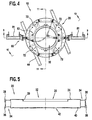
- the bag closing apparatus 10 comprises a housing 20 and a cinching assembly 60.
- the preferred housing 20 includes a split cylindrical body 30 secured between round top and bottom plates 24 and 40.
- the plates have coaxial apertures 26 and 42 such that a cylindrical path 32 extends through the housing 20.
- a plurality of mounting brackets 44 extend from the cylindrical body 30 for mounting the apparatus 10 on a frame (not shown) or other discharge unit (not shown).
- the body 30, plates 24, 40 and brackets 44 are preferably manufactured from sheet metal of approximately 10 or 12 gauge.
- a pair of cylinder mounting boxes 34 are secured to the housing 20 in alignment with the open areas 31 of the split housing body 30.
- Each box 34 has a mounting plate 36 with an aperture 38 extending therethrough.
- a fluid cylinder 81 is mounted to each mounting plate 36 with its piston rod 82 aligned with the respective aperture 38.
- the boxes 34 are preferably manufactured from 14 gauge sheet metal and the plates 36 from one-quarter inch (1 ⁇ 4") steel bar.
- the top and bottom plates 24,40, the body 30, the brackets 44, the boxes 34, and the mounting plates 36 are preferably welded together, but may be secured by other means.
- a support ring 52 is preferably secured to the bottom plate 40 by a plurality of flanges 54 extending therefrom.
- the support ring 52 is preferably manufactured from a half inch (1 ⁇ 2") steel rod and finished smooth on its upper surface.
- the support ring 52 provides support and a smooth guide surface for the pivot arms 72 as will be described in more detail hereinafter.
- a ring 28 depends from the top plate 24 about the aperture 26. The ring 28 also provides a smooth guide surface for the pivot arms 72 as will be described in more detail hereinafter.
- a removable support plate 48 with an aperture 50 therethrough may be attached to the top plate 24 with the apertures 50 and 26 coaxially aligned.
- the support plate aperture 50 is preferably sized to the dimension of the bag spout, i.e., if the spout has a sixteen inch (16") diameter, the support plate aperture 50 will have a slightly oversized diameter.
- the support plate 48 thereby helps prevent sagging of the bag portion into the closing apparatus 10. If a different size spout is used, the support plate 48 can be interchanged.
- An apertured guard 56 may be secured to the bottom plate 40 to help prevent unwanted objects from entering the apparatus 10.
- the support plate 48 and the guard 56 are preferably manufactured from one-quarter inch (1 ⁇ 4") high density polyethylene.
- each pivot arm assembly 70 includes a substantially J-shaped pivot arm 72 extending from a pivot tube 76.
- the pivot arms 72 are preferably manufactured from half inch (1 ⁇ 2") steel rod and may be provided with a tapered tip.
- a link tab 74 extends from each pivot arm 72 for interconnection with a respective actuator assembly 80.
- Each pivot tube 76 includes a hollow body 77 upon which a respective pivot arm 72 is mounted.
- a shaft 78 extends through the hollow body 77 and is pivotably secured with respect to the top and bottom plates 24, 40. Bushings 79 or the like may be utilized about the shaft 78.
- the preferred actuator assemblies 80 include fluid actuated cylinders 81 in communication with an air supply line or the like (not shown).
- a piston rod 82 extends from the cylinder 81 and is connected to an attachment plate 84.
- a pair of link bars 88 are pivotably connected to the attachment plate 84 via a pin 86 or the like. The opposite ends of the link bars 88 are then pivotably connected to a link tab 74 extending from a respective pivot arm 72.
- the link bars 88 By securing one link bar 88 above and one below the attachment plate 84, the link bars 88 properly align with the link tabs 74 of the pivot arms 72 which are at different elevations.
- one actuator assembly 80 may be utilized for each pivot arm assembly 70.
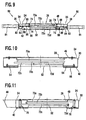
- the four pivot arms 72a-72d are stacked one upon the other and upon the support ring 52.
- the support ring 52 and top ring 28 are preferably spaced such that the pivot arms 72a-72d abut, as shown in Figure 10, but remain slidable relative to one another. The abutting relationship helps prevent the spout from moving between adjacent pivot arms 72.
- the pivot arms 72a-72d are mounted at different heights on their respective pivot tubes 76 to provide proper alignment.
- to provide proper alignment of the fluid actuated cylinders 81 such are preferably mounted off-set from one another. As shown in Figure 9, the higher mounted cylinder 81 actuates pivot arms 72a and 72c and the lower mounted air cylinder 81 actuates pivot arms 72b and 72d.
- the actuator assemblies 80 are non-energized and the pivot arms 72 are in an open, generally circular configuration.
- a spout can be passed through the assembly 10 and engaged with a discharge unit.
- the fluid cylinders 81 are actuated to extend the rods 82.
- the pivotably connected link bars 88 translate the linear force to move the pivotably connected pivot bars 72 along an arcuate path as represented by the arrows A in Figure 13. The arcuate path and the curvature of the pivot arms 72 minimizes the potential for pinching of the spout.
- Actuation of the cylinders 81 continues as the pivot arms 72 constrict the bag to a central region 90.
- the pivot arms 72 are then extended to a position beyond the central region 90 and overlap such that the bag spout forms a "Z" as it travels between the pivot arms 72.
- the over extension is preferred, but may not be required in all applications.
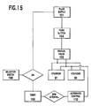
- the preferred operating system 100 of the closing assembly 10 will be described with reference to Figure 15.
- the preferred operating system 100 includes a manual valve 102, a safety push button 104, a selector switch 106, a timer 108, and an automatic control 110.
- the manual valve 102 controls the flow of fluid into the cylinders 81 and is moveable between a nuetral position and "close” and “open” positions wherein fluid is provided to the cylinders 81 to extend or retract the rods 82.
- an operator uses the manual valve 102 to control flow into and out of the cylinder 81 as desired.
- the system 100 also preferably includes a safety push button 104 which closes the fluid supply 101 unless engaged.
- the preferred system 100 also includes an automatic control 110.
- the selector switch 106 To utilize the automatic control 110, the selector switch 106 must be in the "auto” position. If the switch 106 is in the "auto” position, the timer 108 will time the duration the manual valve 102 is in the "close” position. If the manual valve 102 is in the "close” position for a given time interval, for example five seconds, the timer 108 will trigger the automatic control 110.
- the automatic control 110 will then continue to supply fluid pressure to the cylinder 81, irrespective of whether the manual valve 102 or push button 104 are engaged, until the operator moves the selector switch 106 to a "manual" position. With the selector switch in the "manual" position, the operator can use the manual valve 102 to open the cinching assembly 60.
- Other manual and automatic operating systems may also be used.
Landscapes
- Engineering & Computer Science (AREA)
- Mechanical Engineering (AREA)
- General Engineering & Computer Science (AREA)
- Supplying Of Containers To The Packaging Station (AREA)
- Making Paper Articles (AREA)
- Mechanically-Actuated Valves (AREA)
- Specific Sealing Or Ventilating Devices For Doors And Windows (AREA)
- Lift Valve (AREA)
- Power-Operated Mechanisms For Wings (AREA)
- Package Closures (AREA)
- Bag Frames (AREA)
Abstract
Description
Claims (17)
- A bag closing apparatus (10) for unloading bulk bags having a frame structure (20), characterized by;
at least three pivot arms (72;72a-72d), each pivot arm (72a-72d) having first and second ends and an arcuate portion therebetween, pivotably connected to the frame structure (20) adjacent one end thereof and located relative to each other such that each pivot arm (72a-72d) crosses at least two other pivot arms (72a-72d) to define a confined closure area, and actuation means (81) for moving the pivot arms (72a-72d);
the bag closing apparatus receives a bag spout, and the pivot arms (72a-72d) are moveable between spread positions wherein the closure area (32) has a predetermined area and closed positions wherein at least one pivot arm (72a-72d) extends past at least one of the other pivot arms (72a-72d) in the closure area (32) to an overlapped position closing off the predetermined area to cinch the bag spout. - The apparatus of claim 1 wherein each pivot arm (72a-72d) has a substantially J-shape configuration.
- The apparatus of claim 1 wherein each of the pivot arms (72a-72d) is mounted of at a different elevation such that the pivot arms (72a-72d) are stacked.
- The apparatus of claim 1 comprising four pivot arms (72a-72d).
- The apparatus of claim 1 wherein the closure area (32) has a substantially circular configuration with the pivot arms (72a-72d) in the spread positions.
- The apparatus of claim 1 wherein the pivot arms (72a-72d) are extendable beyond a central region (90) to overlap one another [ and pass the closure area].
- The apparatus of claim 1 wherein the actuator means (81) includes a plurality of actuator assemblies, each including a fluid cylinder (81) with an extendable rod (82).
- The apparatus of claim 7 wherein each pivot arm (72a-72d) has a link tab(74) extending therefrom which is pivotably coupled with a first end of a link bar (88), a second end of the link bar (88) coupled to an attachment portion (84) of a respective rod (82).
- The apparatus of claim 8 wherein two link bars (88) are pivotably coupled to the attachment portion (84) of a respective rod (82) such that the rod (81) actuates a pair of pivot arms (72a-72d).
- The apparatus of claim I wherein the frame structure includes a cylindrical housing (20).
- The apparatus of claim 10 wherein the housing (20) includes a cylindrical body (30) extending between opposed top and bottom plates (24, 40).
- The apparatus of claim 11 wherein the top and bottom plates (24, 40) have an aperture (26, 42) therethrough and the apertures (26, 42) are coaxial to define a cylindrical passage (32) through the housing (20).
- The apparatus of claim 11 wherein the housing (20) further comprises a support ring (52) secured proximate the bottom plate (40) such that a lower one of the pivot arms (72a-72d) is tangential thereto.
- The apparatus of claim 13 wherein a ring member (28) depends from the top plate (24) such that an upper one of the pivot arms (72a-72d) is tangential thereto.
- The apparatus of claim 14 wherein the pivot arms (72a-72d) have a combined vertical dimension and the support ring (52) and ring member (28) are spaced a distance approximate the combined vertical dimension.
- The apparatus of claim 11 wherein the housing (20) further comprises a removable support plate (48) having an aperture (50) therethrough.
- The apparatus of claim 1, further comprising a bag located in the bag closing apparatus (10) having a bag spout which extends through the confined closure area, and wherein in the closed positions, the pivot arms (72a-72d) are extended to a position beyond a central region (90) and overlap such that the bag spout forms a "Z" as it extends between the pivot arms (72a-72d).
Applications Claiming Priority (3)
| Application Number | Priority Date | Filing Date | Title |
|---|---|---|---|
| US558706 | 2000-04-26 | ||
| US09/558,706 US6502367B1 (en) | 2000-04-26 | 2000-04-26 | Bag closing apparatus |
| PCT/US2001/013352 WO2001081177A1 (en) | 2000-04-26 | 2001-04-26 | Bag closing apparatus |
Publications (2)
| Publication Number | Publication Date |
|---|---|
| EP1276669A1 EP1276669A1 (en) | 2003-01-22 |
| EP1276669B1 true EP1276669B1 (en) | 2004-06-23 |
Family
ID=24230626
Family Applications (1)
| Application Number | Title | Priority Date | Filing Date |
|---|---|---|---|
| EP01930755A Expired - Lifetime EP1276669B1 (en) | 2000-04-26 | 2001-04-26 | Bag closing apparatus |
Country Status (10)
| Country | Link |
|---|---|
| US (3) | US6502367B1 (en) |
| EP (1) | EP1276669B1 (en) |
| AT (1) | ATE269810T1 (en) |
| AU (2) | AU2001257260B2 (en) |
| CA (1) | CA2406221C (en) |
| DE (1) | DE60103996T2 (en) |
| DK (1) | DK1276669T3 (en) |
| ES (1) | ES2222994T3 (en) |
| NZ (1) | NZ522149A (en) |
| WO (1) | WO2001081177A1 (en) |
Families Citing this family (25)
| Publication number | Priority date | Publication date | Assignee | Title |
|---|---|---|---|---|
| DE19934154C1 (en) * | 1999-07-26 | 2000-10-26 | Poly Clip System Gmbh & Co Kg | Sausage stuffing apparatus has overlapping tying components consisting of bent strips arranged symmetrically about casing which can be pivoted towards each other to define orifice whose size is reduced to tie off casing when it is full |
| US6502367B1 (en) * | 2000-04-26 | 2003-01-07 | Flexicon Corporation | Bag closing apparatus |
| EP1188672A1 (en) * | 2000-09-18 | 2002-03-20 | Mars B.V. | Method and device for packaging a food product, such as a candy, as well as a packaged candy |
| US7712285B2 (en) * | 2001-05-02 | 2010-05-11 | Playtex Products, Inc. | Waste disposal device including a sensing mechanism for delaying the rotation of a cartridge |
| US6860258B2 (en) * | 2002-03-11 | 2005-03-01 | Kenneth R. Farrell | Paintball loader |
| GB0206775D0 (en) * | 2002-03-22 | 2002-05-01 | Flomat Bagfilla Internat Ltd | Materials handling equipment |
| US7322556B2 (en) * | 2005-09-08 | 2008-01-29 | Bernstein Robert E | Pinch valve for regulating fluid flow |
| US20070173192A1 (en) * | 2006-01-20 | 2007-07-26 | Arzel Technology, Inc. | Small duct high velocity damper assembly |
| US8528606B1 (en) | 2007-11-14 | 2013-09-10 | Michael J. Seiver | Apparatus and methods for filling containers with non-liquids |
| US8282069B2 (en) | 2008-11-25 | 2012-10-09 | Acrison, Inc. | Cinch valve |
| DE102011055850B3 (en) * | 2011-11-30 | 2012-11-29 | Sartorius Weighing Technology Gmbh | pinch |
| US8955819B2 (en) | 2012-03-22 | 2015-02-17 | Acrison, Inc. | Cinch valve with elastic elements |
| JP6187053B2 (en) * | 2012-09-18 | 2017-08-30 | 株式会社リコー | Information processing system, information processing apparatus, and program |
| EP2769622B1 (en) * | 2013-02-20 | 2017-09-13 | Poly-clip System GmbH & Co. KG | Polygonal shaped filling tube with corresponding casing brake |
| US9451730B2 (en) * | 2013-03-06 | 2016-09-20 | Amazon Technologies, Inc. | Managing airflow supplied through soft ducts |
| US9980813B2 (en) | 2014-04-28 | 2018-05-29 | Cook Medical Technologies Llc | Selective fluid barrier valve device and method of treatment |
| DE102015210581A1 (en) * | 2015-06-10 | 2016-12-15 | Bayerische Motoren Werke Aktiengesellschaft | braiding |
| CN206871754U (en) * | 2017-04-21 | 2018-01-12 | 京东方科技集团股份有限公司 | Storage device and collecting bag |
| US10495693B2 (en) | 2017-06-01 | 2019-12-03 | General Electric Company | Wind turbine fault detection using acoustic, vibration, and electrical signals |
| GB2571823B (en) * | 2018-01-15 | 2021-03-24 | Spiroflow Ltd | Pinch valve |
| CN108584238A (en) * | 2018-06-16 | 2018-09-28 | 上海拓牛智能科技有限公司 | Refuse bag packing mechanism and intelligent garbage bin |
| WO2020163767A1 (en) * | 2019-02-08 | 2020-08-13 | Worcester Polytechnic Institute | Fluid flow control valve |
| US10676227B1 (en) | 2019-05-30 | 2020-06-09 | Schenck Process Llc | Bulk bag closing system |
| CN111779859A (en) * | 2020-07-04 | 2020-10-16 | 上海彬泽机电设备安装有限公司 | An aperture valve and a ton bag unloading station using the aperture valve |
| DE102020121356B4 (en) * | 2020-08-13 | 2022-07-07 | Sartorius Stedim Systems GmbH | pinch valve |
Family Cites Families (18)
| Publication number | Priority date | Publication date | Assignee | Title |
|---|---|---|---|---|
| US1809091A (en) * | 1928-04-05 | 1931-06-09 | Frederick C Bogk | Bag filler |
| DE1882434U (en) * | 1962-10-24 | 1963-11-07 | Richard Jun Nicolaus | FOLDING DEVICE ON PACKAGING MACHINES. |
| US3473779A (en) * | 1965-04-12 | 1969-10-21 | Henry E Gustafson | Flexible tube valve having positive opening and closing means |
| US3841535A (en) * | 1969-06-10 | 1974-10-15 | J Taupin | Valves for controlling the flow of finely-divided material from a hopper |
| US4322054A (en) * | 1980-12-29 | 1982-03-30 | Red Valve Company, Inc. | Pinch valve |
| US4569502A (en) * | 1984-09-04 | 1986-02-11 | Miller Sales & Engineering, Inc. | Pinch valve |
| US5121682A (en) * | 1990-06-01 | 1992-06-16 | Clements Industries, Inc. | Twist tie feed device |
| JPH04303303A (en) * | 1991-03-29 | 1992-10-27 | Fuji Heavy Ind Ltd | Garbage container transportation device for multistoried building |
| US5230497A (en) * | 1991-05-10 | 1993-07-27 | Bunnell Incorporated | Multiple state valve |
| US5391154A (en) * | 1993-08-30 | 1995-02-21 | United States Surgical Corporation | Trocar seal system |
| CA2125946C (en) * | 1994-06-15 | 2002-04-30 | Robert Lauzon | Bagging machine with in-line attaching mechanism |
| GB9513685D0 (en) * | 1995-07-05 | 1995-09-06 | Spiroflow Ltd | Bag discharge |
| DE19606654C1 (en) * | 1996-02-23 | 1997-04-17 | Poly Clip System Gmbh & Co Kg | Machine portioning filling into individual packs formed from flexible tube |
| US6089527A (en) * | 1997-10-03 | 2000-07-18 | Medisystems Technology Corporation | Squeeze clamp for flexible tubing |
| IL127029A (en) * | 1998-11-12 | 2002-03-10 | Medivice Systems Ltd | Pinch clamp |
| DE19934154C1 (en) * | 1999-07-26 | 2000-10-26 | Poly Clip System Gmbh & Co Kg | Sausage stuffing apparatus has overlapping tying components consisting of bent strips arranged symmetrically about casing which can be pivoted towards each other to define orifice whose size is reduced to tie off casing when it is full |
| US6502367B1 (en) * | 2000-04-26 | 2003-01-07 | Flexicon Corporation | Bag closing apparatus |
| JP4573010B2 (en) * | 2000-07-07 | 2010-11-04 | 旭有機材工業株式会社 | Pinch valve |
-
2000
- 2000-04-26 US US09/558,706 patent/US6502367B1/en not_active Expired - Lifetime
-
2001
- 2001-04-26 AT AT01930755T patent/ATE269810T1/en not_active IP Right Cessation
- 2001-04-26 CA CA002406221A patent/CA2406221C/en not_active Expired - Lifetime
- 2001-04-26 AU AU2001257260A patent/AU2001257260B2/en not_active Expired
- 2001-04-26 AU AU5726001A patent/AU5726001A/en active Pending
- 2001-04-26 DE DE60103996T patent/DE60103996T2/en not_active Expired - Lifetime
- 2001-04-26 ES ES01930755T patent/ES2222994T3/en not_active Expired - Lifetime
- 2001-04-26 EP EP01930755A patent/EP1276669B1/en not_active Expired - Lifetime
- 2001-04-26 DK DK01930755T patent/DK1276669T3/en active
- 2001-04-26 WO PCT/US2001/013352 patent/WO2001081177A1/en not_active Ceased
- 2001-04-26 NZ NZ522149A patent/NZ522149A/en not_active IP Right Cessation
-
2003
- 2003-01-07 US US10/337,484 patent/US6892510B2/en not_active Expired - Lifetime
-
2005
- 2005-05-13 US US11/129,429 patent/US7032875B2/en not_active Expired - Lifetime
Also Published As
| Publication number | Publication date |
|---|---|
| US20050218358A1 (en) | 2005-10-06 |
| US6892510B2 (en) | 2005-05-17 |
| US6502367B1 (en) | 2003-01-07 |
| DK1276669T3 (en) | 2004-09-27 |
| DE60103996D1 (en) | 2004-07-29 |
| AU2001257260B2 (en) | 2004-09-30 |
| EP1276669A1 (en) | 2003-01-22 |
| ES2222994T3 (en) | 2005-02-16 |
| AU5726001A (en) | 2001-11-07 |
| ATE269810T1 (en) | 2004-07-15 |
| US7032875B2 (en) | 2006-04-25 |
| CA2406221C (en) | 2006-12-19 |
| NZ522149A (en) | 2004-05-28 |
| DE60103996T2 (en) | 2005-06-30 |
| WO2001081177A1 (en) | 2001-11-01 |
| US20040000122A1 (en) | 2004-01-01 |
| CA2406221A1 (en) | 2001-11-01 |
Similar Documents
| Publication | Publication Date | Title |
|---|---|---|
| CA2406221C (en) | Bag closing apparatus | |
| AU2001257260A1 (en) | Bag closing apparatus | |
| US5944470A (en) | Flexible bulk container unloader | |
| US5324097A (en) | Bottom dump trailer | |
| US4569502A (en) | Pinch valve | |
| EP0835829B1 (en) | Discharge device for a bulk bag and method of use | |
| US7223058B2 (en) | Bulk bag discharging system assembly | |
| US4797050A (en) | Apparatus for lifting and tilting drums of flowable material | |
| US20080173373A1 (en) | Flexible container discharge apparatus and method | |
| US5699730A (en) | Bag squeezer | |
| US5413157A (en) | Bag filling apparatus having dust-tight spout | |
| US4407434A (en) | Apparatus having an improved flow control pinch valve for dispensing flowable materials | |
| AU2001267037B9 (en) | Apparatus for securing a bulk bag to a discharge spout | |
| US6290098B1 (en) | Flow promotion apparatus | |
| CZ209297A3 (en) | Device for grasping vessels | |
| DE3403534A1 (en) | Device for filling plastic flat-bag packages with gas and welding them shut | |
| US4563864A (en) | Apparatus for filling sacks | |
| NO319100B1 (en) | Packing machine for filling a container with a primary product and a secondary product | |
| US5294186A (en) | Bottom dump trailer | |
| WO2005087624A2 (en) | Emptying device for a bulk-goods container and bulk goods container | |
| US3098537A (en) | Large volume weigher | |
| NL9300823A (en) | Device and method for transporting and dispensing feed. | |
| GB2302932A (en) | Bag discharge valve | |
| US4149564A (en) | Proportioning valve | |
| JPS5820756B2 (en) | Ryuutaiisouseigiyosouchi |
Legal Events
| Date | Code | Title | Description |
|---|---|---|---|
| PUAI | Public reference made under article 153(3) epc to a published international application that has entered the european phase |
Free format text: ORIGINAL CODE: 0009012 |
|
| 17P | Request for examination filed |
Effective date: 20021102 |
|
| AK | Designated contracting states |
Kind code of ref document: A1 Designated state(s): AT BE CH CY DE DK ES FI FR GB GR IE IT LI LU MC NL PT SE TR |
|
| AX | Request for extension of the european patent |
Free format text: AL;LT;LV;MK;RO;SI |
|
| GRAP | Despatch of communication of intention to grant a patent |
Free format text: ORIGINAL CODE: EPIDOSNIGR1 |
|
| GRAS | Grant fee paid |
Free format text: ORIGINAL CODE: EPIDOSNIGR3 |
|
| GRAA | (expected) grant |
Free format text: ORIGINAL CODE: 0009210 |
|
| AK | Designated contracting states |
Kind code of ref document: B1 Designated state(s): AT BE CH CY DE DK ES FI FR GB GR IE IT LI LU MC NL PT SE TR |
|
| PG25 | Lapsed in a contracting state [announced via postgrant information from national office to epo] |
Ref country code: LI Free format text: LAPSE BECAUSE OF FAILURE TO SUBMIT A TRANSLATION OF THE DESCRIPTION OR TO PAY THE FEE WITHIN THE PRESCRIBED TIME-LIMIT Effective date: 20040623 Ref country code: TR Free format text: LAPSE BECAUSE OF FAILURE TO SUBMIT A TRANSLATION OF THE DESCRIPTION OR TO PAY THE FEE WITHIN THE PRESCRIBED TIME-LIMIT Effective date: 20040623 Ref country code: FI Free format text: LAPSE BECAUSE OF FAILURE TO SUBMIT A TRANSLATION OF THE DESCRIPTION OR TO PAY THE FEE WITHIN THE PRESCRIBED TIME-LIMIT Effective date: 20040623 Ref country code: CH Free format text: LAPSE BECAUSE OF FAILURE TO SUBMIT A TRANSLATION OF THE DESCRIPTION OR TO PAY THE FEE WITHIN THE PRESCRIBED TIME-LIMIT Effective date: 20040623 Ref country code: AT Free format text: LAPSE BECAUSE OF FAILURE TO SUBMIT A TRANSLATION OF THE DESCRIPTION OR TO PAY THE FEE WITHIN THE PRESCRIBED TIME-LIMIT Effective date: 20040623 |
|
| REG | Reference to a national code |
Ref country code: GB Ref legal event code: FG4D |
|
| REG | Reference to a national code |
Ref country code: CH Ref legal event code: EP |
|
| REG | Reference to a national code |
Ref country code: IE Ref legal event code: FG4D |
|
| REF | Corresponds to: |
Ref document number: 60103996 Country of ref document: DE Date of ref document: 20040729 Kind code of ref document: P |
|
| PG25 | Lapsed in a contracting state [announced via postgrant information from national office to epo] |
Ref country code: GR Free format text: LAPSE BECAUSE OF FAILURE TO SUBMIT A TRANSLATION OF THE DESCRIPTION OR TO PAY THE FEE WITHIN THE PRESCRIBED TIME-LIMIT Effective date: 20040923 |
|
| REG | Reference to a national code |
Ref country code: DK Ref legal event code: T3 |
|
| REG | Reference to a national code |
Ref country code: SE Ref legal event code: TRGR |
|
| LTIE | Lt: invalidation of european patent or patent extension |
Effective date: 20040623 |
|
| REG | Reference to a national code |
Ref country code: CH Ref legal event code: PL |
|
| REG | Reference to a national code |
Ref country code: ES Ref legal event code: FG2A Ref document number: 2222994 Country of ref document: ES Kind code of ref document: T3 |
|
| ET | Fr: translation filed | ||
| PG25 | Lapsed in a contracting state [announced via postgrant information from national office to epo] |
Ref country code: IE Free format text: LAPSE BECAUSE OF NON-PAYMENT OF DUE FEES Effective date: 20050426 Ref country code: CY Free format text: LAPSE BECAUSE OF FAILURE TO SUBMIT A TRANSLATION OF THE DESCRIPTION OR TO PAY THE FEE WITHIN THE PRESCRIBED TIME-LIMIT Effective date: 20050426 Ref country code: LU Free format text: LAPSE BECAUSE OF NON-PAYMENT OF DUE FEES Effective date: 20050426 |
|
| PLBE | No opposition filed within time limit |
Free format text: ORIGINAL CODE: 0009261 |
|
| STAA | Information on the status of an ep patent application or granted ep patent |
Free format text: STATUS: NO OPPOSITION FILED WITHIN TIME LIMIT |
|
| PG25 | Lapsed in a contracting state [announced via postgrant information from national office to epo] |
Ref country code: MC Free format text: LAPSE BECAUSE OF NON-PAYMENT OF DUE FEES Effective date: 20050430 |
|
| 26N | No opposition filed |
Effective date: 20050324 |
|
| PG25 | Lapsed in a contracting state [announced via postgrant information from national office to epo] |
Ref country code: PT Free format text: LAPSE BECAUSE OF NON-PAYMENT OF DUE FEES Effective date: 20041123 |
|
| REG | Reference to a national code |
Ref country code: FR Ref legal event code: PLFP Year of fee payment: 16 |
|
| REG | Reference to a national code |
Ref country code: FR Ref legal event code: PLFP Year of fee payment: 17 |
|
| REG | Reference to a national code |
Ref country code: FR Ref legal event code: PLFP Year of fee payment: 18 |
|
| PGFP | Annual fee paid to national office [announced via postgrant information from national office to epo] |
Ref country code: BE Payment date: 20200316 Year of fee payment: 20 |
|
| PGFP | Annual fee paid to national office [announced via postgrant information from national office to epo] |
Ref country code: FR Payment date: 20200312 Year of fee payment: 20 |
|
| PGFP | Annual fee paid to national office [announced via postgrant information from national office to epo] |
Ref country code: DE Payment date: 20200415 Year of fee payment: 20 Ref country code: DK Payment date: 20200414 Year of fee payment: 20 Ref country code: ES Payment date: 20200504 Year of fee payment: 20 Ref country code: NL Payment date: 20200417 Year of fee payment: 20 |
|
| PGFP | Annual fee paid to national office [announced via postgrant information from national office to epo] |
Ref country code: IT Payment date: 20200312 Year of fee payment: 20 Ref country code: GB Payment date: 20200416 Year of fee payment: 20 Ref country code: SE Payment date: 20200415 Year of fee payment: 20 |
|
| REG | Reference to a national code |
Ref country code: DE Ref legal event code: R071 Ref document number: 60103996 Country of ref document: DE |
|
| REG | Reference to a national code |
Ref country code: NL Ref legal event code: MK Effective date: 20210425 |
|
| REG | Reference to a national code |
Ref country code: DK Ref legal event code: EUP Expiry date: 20210426 |
|
| REG | Reference to a national code |
Ref country code: GB Ref legal event code: PE20 Expiry date: 20210425 |
|
| REG | Reference to a national code |
Ref country code: BE Ref legal event code: MK Effective date: 20210426 |
|
| REG | Reference to a national code |
Ref country code: SE Ref legal event code: EUG |
|
| PG25 | Lapsed in a contracting state [announced via postgrant information from national office to epo] |
Ref country code: GB Free format text: LAPSE BECAUSE OF EXPIRATION OF PROTECTION Effective date: 20210425 |
|
| REG | Reference to a national code |
Ref country code: ES Ref legal event code: FD2A Effective date: 20220103 |
|
| PG25 | Lapsed in a contracting state [announced via postgrant information from national office to epo] |
Ref country code: ES Free format text: LAPSE BECAUSE OF EXPIRATION OF PROTECTION Effective date: 20210427 |