EP1276279A1 - Lossless serving radio network subsystem (SRNS) relocation procedure in a wireless communications system - Google Patents
Lossless serving radio network subsystem (SRNS) relocation procedure in a wireless communications system Download PDFInfo
- Publication number
- EP1276279A1 EP1276279A1 EP02011771A EP02011771A EP1276279A1 EP 1276279 A1 EP1276279 A1 EP 1276279A1 EP 02011771 A EP02011771 A EP 02011771A EP 02011771 A EP02011771 A EP 02011771A EP 1276279 A1 EP1276279 A1 EP 1276279A1
- Authority
- EP
- European Patent Office
- Prior art keywords
- srns
- mobile unit
- sdus
- trns
- sdu
- Prior art date
- Legal status (The legal status is an assumption and is not a legal conclusion. Google has not performed a legal analysis and makes no representation as to the accuracy of the status listed.)
- Granted
Links
Images


Classifications
-
- H—ELECTRICITY
- H04—ELECTRIC COMMUNICATION TECHNIQUE
- H04W—WIRELESS COMMUNICATION NETWORKS
- H04W36/00—Hand-off or reselection arrangements
- H04W36/02—Buffering or recovering information during reselection ; Modification of the traffic flow during hand-off
-
- H—ELECTRICITY
- H04—ELECTRIC COMMUNICATION TECHNIQUE
- H04L—TRANSMISSION OF DIGITAL INFORMATION, e.g. TELEGRAPHIC COMMUNICATION
- H04L69/00—Network arrangements, protocols or services independent of the application payload and not provided for in the other groups of this subclass
- H04L69/40—Network arrangements, protocols or services independent of the application payload and not provided for in the other groups of this subclass for recovering from a failure of a protocol instance or entity, e.g. service redundancy protocols, protocol state redundancy or protocol service redirection
-
- H—ELECTRICITY
- H04—ELECTRIC COMMUNICATION TECHNIQUE
- H04W—WIRELESS COMMUNICATION NETWORKS
- H04W36/00—Hand-off or reselection arrangements
- H04W36/12—Reselecting a serving backbone network switching or routing node
-
- H—ELECTRICITY
- H04—ELECTRIC COMMUNICATION TECHNIQUE
- H04W—WIRELESS COMMUNICATION NETWORKS
- H04W92/00—Interfaces specially adapted for wireless communication networks
- H04W92/16—Interfaces between hierarchically similar devices
- H04W92/22—Interfaces between hierarchically similar devices between access point controllers
Definitions
- the present invention relates to a wireless communications network.
- the present invention discloses a method for performing lossless relocation of a serving radio network subsystem.
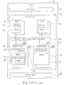
- Fig.1 is a block diagram of a wireless communications network 10.
- the wireless communications network 10 comprises a plurality of radio network subsystems (RNSs) 20 in communications with a core network (CN) 30.
- Each RNS 20 comprises one radio network controller (RNC) 22 that is in communications with a plurality of node Bs 24.
- Each node B 24 is a transceiver, which is adapted to send and receive wireless signals.
- the wireless communications network 10 assigns a mobile unit 40 to a particular RNS 20, which is then termed the serving RNS (SRNS) 20s of the mobile unit 40. Data destined for the mobile unit 40 is sent by the CN 30 to the SRNS 20s.
- SRNS serving RNS
- This data is in the form of service data units (SDUs) 28 that are held by the RNC 22 of the SRNS 20s pending transmittal by one of the Node Bs 24.
- the RNC 22 selects a node B 24 that is best able to accurately transmit the SDUs 28 to the mobile unit 40. Such a selection will depend, for example, upon the location of the mobile unit 40 within the domain of the SRNS 20s.
- the mobile unit 40 broadcasts SDUs 48 to the wireless communications network 10, which are then picked up by the SRNS 20s and forwarded to the CN 30. Occasionally, the mobile unit 40 may move close to the domain of another RNS 20, which is termed a drift RNS (DRNS) 20d.
- DRNS drift RNS
- a node B 24 of the DRNS 20d may pick up one or more of the SDUs 48 transmitted by the mobile unit 40.
- the RNC 22 of the DRNS 20d forwards the received SDUs 48 to the SRNS 20s.
- the SRNS 20s then forwards these received SDUs 48 to the CN 30. Consequently, all communications between the mobile unit 40 and the CN 30 must pass through the SRNS 20s.
- Fig.2 is a block diagram of the RNC 22 of the SRNS 20s. Communications between the mobile unit 40 and the RNC 22 are effected through a multi-layered communications protocol that has a packet data convergence protocol (PDCP) layer 22p in communications with an upper layer 22u and a lower layer 22L.
- the PDCP layer 22p receives a plurality of SDUs 28 from the upper layer 22u.
- Each SDU 28 includes a header 28h and data 28d.
- the primary purpose of the SDU 28 is to carry the data 28d to a destination indicated by the header 28h.
- the header 28h is analogous to an Internet protocol (IP) header.
- IP Internet protocol
- the header 28h may carry a lot of information that is redundant or repeated through the other SDU headers 28h in the other SDUs 28.
- One purpose of the PDCP layer 22p is to compresses the headers 28h so as to maximize bandwidth. This compression is performed by way of a header compressor/decompressor 22c.
- the header compressor/decompressor accepts an SDU 28 and generates a PDCP protocol data unit (PDCP PDU) 29.
- a PDCP PDU 29 includes a PDCP header 29h and data 29d.
- the data 29d includes compressed header data 29x that is generated by the header compressor/decompressor 22c according to the header 28h.
- Each PDCP PDU 29s is incrementally assigned a 16-bit sequence number (SN) 29s by the PDCP layer 22p. That is, each sequentially successive PDCP PDU 29 is assigned an incrementally higher SN 29s. For example, a first PDCP PDU 29 may be assigned an SN 29s of 62. A second PDCP PDU 29 immediately after the first PDCP PDU 29 would thus be assigned an SN 29s of 63, and so on. The SNs 29s are not actually a part of the PDCP PDUs 29, but are internally maintained by the PDCP layer 22p. The PDCP PDUs 29 are then delivered to the lower layer 22L for transmission.
- SN sequence number
- each PDCP PDU 29 has an assigned SN 29s
- each corresponding SDU 28 also has an associated SN 29s. That is, the SNs 29s are associated with both the PDCP PDUs 29 and the corresponding SDUs 28. Since bandwidth is to be maximized by the compression of the headers 28h, each PDCP PDU 29 should, ideally, be smaller in size than its corresponding SDU 28. To ensure that this is indeed the case, the PDCP header 29h should be kept as small as possible.
- the type of header compression used for the header compressor/decompressor 22c will depend upon the format of the headers 28h. As an example, though, if the headers 28h are IP headers, then the compression performed could conform to the IP industry standard RFC 2507.
- PDCP PDUs 27 received from the lower layer 22L are fed into the header compressor/decompressor 22c to generate the corresponding SDUs 48.
- the SDUs 48 so generated are then delivered to the upper layer 22u.
- Each PDCP PDU 27 has a 16-bit SN 27s assigned to the PDCP PDU 27 by the PDCP layer 22p, in a manner that is analogous to the SNs 29s. These SNs 27s are also associated with the corresponding SDUs 48.
- SRNS relocation procedure a transfer process is enacted. This process is termed a SRNS relocation procedure, and should be lossless. Lossless means that no SDUs 28, 48 are lost during the relocation procedure.
- Fig.3 is a block diagram of the mobile unit 40 undergoing a lossless SRNS relocation procedure.
- the DRNS 20d becomes a target RNS (TRNS) 20t.
- TRNS target RNS
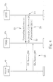
- Fig.4 is a message sequence chart for the prior art lossless SRNS relocation procedure.
- the SRNS 20s sends forwarding information 50 to the TRNS 20t. This forwarding information includes a downlink sending sequence number (DL Send_SN) 52, an uplink receiving sequence number (UL Receive_SN) 54, and all unconfirmed SDUs 28.
- DL Send_SN downlink sending sequence number
- UL Receive_SN uplink receiving sequence number
- the multi-layered communications protocol used by both the SRNS 20s and the mobile unit 40 enables the mobile unit 40 to confirm those PDCP PDUs 29 transmitted by the SRNS 20s that are successfully received by the mobile unit 40. Any PDCP PDUs 29 not explicitly confirmed as received by the mobile unit 40 are termed unconfirmed PDCP PDUs 29. As there is a one-to-one correspondence between SDUs 28 and PDCP PDUs 29, an unconfirmed PDCP PDU 29 means that there is a corresponding unconfirmed SDU 28. These unconfirmed SDUs 28 are forwarded by the SRNS 20s to the TRNS 20t.
- the DL Send_SN 52 is the value of the SN 29s associated with the sequentially earliest unconfirmed PDCP PDU 29. As the SNs 29s are not explicitly carried in the SDUs 28, this enables the TRNS 20t to properly associate an SN 29s for the corresponding PDCP PDU 29 of each forwarded SDU 28.
- the UL Receive_SN 54 is the value of the SN 27s associated with the PDCP PDU 27 that the SRNS 20s next expects to receive from the mobile unit 40. This enables the TRNS 20t to properly associate an SN 27s for each subsequently received PDCP PDU 27 from the mobile unit 40. The TRNS 20t sends the UL Receive_SN 54 to the mobile unit 40.
- the mobile unit 40 can determine which packets 48 to begin sending to the TRNS 20s under its guise as the new SRNS 20s.
- the mobile unit 40 sends a downlink receiving sequence number (DL Receive_SN) 58 to the TRNS.
- the DL Receive_SN 58 holds the value of the SN 29s of the next PDCP PDU 29 that the mobile unit 40 is expecting to receive from the TRNS 20t. From this, the TRNS 20t can learn which of the forwarded unconfirmed SDUs 28 to begin sending to the mobile unit 40.
- DL Receive_SN downlink receiving sequence number
- the DL Send_SN 52 would have a value of 51, and the UL Receive_SN 54 would have a value of 200.
- the DL Receive_SN 58 will hold a value that is between 51 and 100, depending on how many of the unconfirmed PDCP PDUs 29 were actually received by the mobile unit 40, but not yet confirmed. If, for example, the DL Receive_SN 58 holds a value of 90, then the TRNS 20t knows that it may discard the forwarded SDUs 28 that have associated SNs 29s that run from 51 to 89, and will begin transmitting those forwarded SDUs 28 with associated SNs 29s that are from 90 and above.
- the DL Receive_SN 58 will either be sequentially before the DL Send_SN 52 or sequentially after the SN 29s associated with the sequentially last forwarded SDU 28.
- Such an occurrence means that the SNs 29s and/or 27s maintained by the RNC 22 of the SRNS 20s are out of synchronization with corresponding SNs maintained by the mobile unit 40.
- a re-synchronization procedure is thus enacted by the TRNS 20t.
- the TRNS 20t transmits PDCP PDUs 29 that explicitly contain their associated SNs 29s in their PDCP headers 29h, beginning with the PDCP PDU 29 corresponding with the sequentially earliest forwarded SDU 28.
- the TRNS 20t stops including the SNs 29s in the PDCP headers 29h. Including the SN 29s in the PDCP header 29h is not desired, as it increases the size of the PDCP header 29h, but it does enable the mobile phone to synchronize its internally maintained SNs with those of the SRNS 20s.
- SRNS serving radio network subsystem
- the preferred embodiment of the present invention discloses a method for performing lossless relocation of a serving radio network subsystem (SRNS) in a wireless communications network.
- Radio network subsystems RNSs
- RNSs Radio network subsystems
- CN core network
- One of the RNSs is an SRNS
- TRNS target RNS
- the SRNS is in wireless communications with a mobile unit to provide service data units (SDUs) from the CN to the mobile unit.
- SDUs service data units
- the SRNS associates a sequence number (SN) with each of the SDUs, and the mobile unit is capable of confirming to the SRNS SDUs received from the SRNS.
- Forwarding information is provided by SRNS to the TRNS.
- the forwarding information includes SDUs unconfirmed as received by the mobile unit, a first SN that is the SN of the sequentially last unconfirmed SDU actually transmitted to the mobile unit by the SRNS, and a second SN that is the SN of the sequentially earliest unconfirmed SDU. Finally, the TRNS is made the new SRNS for the mobile unit.
- the TRNS can determine if the mobile unit is responding to the lossless SRNS procedure with an SN that is sequentially too far ahead, and thus more accurately determine when a re-synchronization process should be performed.
- Fig.1 is a block diagram of a wireless communications system.
- Fig.2 is a block diagram of a radio network controller (RNC) of a serving radio network subsystem (SRNS) depicted in Fig.1.
- RNC radio network controller
- SRNS serving radio network subsystem
- Fig.3 is a block diagram of a mobile unit of Fig.1 undergoing a lossless SRNS relocation procedure.
- Fig.4 is a message sequence chart for the prior art lossless SRNS relocation procedure.
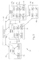
- Fig.5 is a block diagram of a wireless communications system according to the present invention method.
- Fig.6 is a message sequence chart for the present invention lossless SRNS relocation procedure.
- a mobile unit may be a mobile telephone, a handheld transceiver, a base station, a personal data assistant (PDA), a computer, or any other device that requires a wireless exchange of data. It should be understood that many means may be used for the physical layer to effect wireless transmissions, and that any such means may be used for the system hereinafter disclosed.
- PDA personal data assistant
- Fig. 5 is a block diagram of a wireless communications system 50 according to the present invention method.
- the wireless communications system 50 comprises a core network (CN) 60 in communications with a plurality of radio network subsystems (RNSs) 70.
- Each RNS 70 comprises one radio network controller (RNC) 22 in communications with a plurality of node Bs 74.
- Each node B 74 is a transceiver designed to send wireless signals to, and receive wireless signals from, a mobile unit 80.
- Each RNC 72 controls its respective node Bs 74 to most efficiently communicate with the mobile unit 80.
- the mobile unit 80 is assigned to a particular RNS 70, which is termed a serving RNS (SRNS) 70s.
- the mobile unit 80 sends and receives data to the CN 60 through the SRNS 70s.
- the SRNS 70s is thus the primary host of the mobile unit 80, acting as a data gateway for the mobile unit 80 to the CN 60.
- SDUs Service data units
- Each SDU 78 has an associated 16-bit sequence number (SN) 78s, which is generated by the RNC 72 of the SRNS 70.
- the SNs 78s are assigned to their respective SDUs 78 with values that indicate the sequential ordering of the SDUs 78.
- SDUs 78 that are sequentially early will tend to have associated SNs 78s that are less than those of sequentially later SDUs 78.
- the mobile unit 80 assigns an SN 88s to each SDU 88 received from the SRNS 70s.
- the associated SN 78s should be identical to the SN 88s for the corresponding received SDU 88. This is termed synchronization between the SRNS 70s and the mobile unit 80. If it is determined that the SNs 78s and 88s are not properly synchronized with each other, then a re-synchronization procedure must be initiated.
- the mobile unit 80 is able to inform the SRNS 70s that the mobile unit 80 has successfully received an SDU 88 corresponding to a transmitted SDU 78. This is termed confirming the SDU 78. SDUs 78 are confirmed in sequence. That is, the mobile unit 80 should not confirm that a sequentially later SDU 78 has been received before confirming all sequentially earlier intervening SDUs 78. Any SDU 78 that has not been explicitly confirmed by the mobile unit 80 is termed an unconfirmed SDU 78.
- SDUs 78 termed unconfirmed that have been transmitted by the SRNS 70s and not confirmed as received by the mobile unit 80, but also any SDU 78 that has not yet been transmitted by the SRNS 70s is termed an unconfirmed SDU 78.
- the SN 78s is not carried by its associated SDU 78.
- the SNs 78s are explicitly carried by their respective SDUs 78.
- the mobile unit 80 uses the associated SN 78s embedded within the SDU 88 to set the associated SN 88s.
- the mobile unit 80 confirms the corresponding SDU 78, which terminates the re-synchronization procedure.
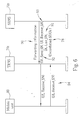
- Fig.6 is a message sequence chart for the present invention method for a lossless SRNS relocation procedure.
- the SRNS 70s sends forwarding information 90 to the TRNS 70t.
- the forwarding information 90 includes a first value 91 (hereinafter termed the first SN 91), a second value 92 (hereinafter termed the second SN 92), a third value 93 (hereinafter termed the third SN 93), and all unconfirmed SDUs 78, regardless of whether or not the unconfirmed SDUs 78 have actually been transmitted by the SRNS 70s.
- the TRNS 70t thereby acquires forwarded SDUs 78f from the forwarding information 90.
- the second SN 92 is a downlink sending sequence number (DL Send_SN) 92, and is the SN 78s associated with the sequentially earliest unconfirmed SDU 78 in the forwarding information 90. As the SNs 78s are not explicitly carried by the SDUs 78 in the forwarding information 90, the second SN 92 enables the TRNS 70t to properly associate an SN 78fs for each forwarded SDU 78f. Each SN 78fs should be identical to its corresponding SN 78s.
- DL Send_SN downlink sending sequence number
- the first SN 91 is a downlink last-sent sequence number (DL Last_SN) 91, and is the SN 78s associated with the sequentially earliest unconfirmed SDU 78 in the forwarding information 90 that has not been transmitted by the SRNS 70s.
- the first SN 91 thereby enables the TRNS 70t to differentiate forwarded SDUs 78f that have already been transmitted by the SRNS 70s from forwarded SDUs 78f that have not yet been transmitted by the SRNS 70s, and is a key point of the present invention method.
- the third SN 93 is an uplink received sequence number (UL Receive_SN) 93, and is an SN 78rs associated by the SRNS 70s of an SDU 78r that the SRNS 70s next expects to receive from the mobile unit 80.
- the third SN 93 thereby enables the TRNS 70t to associate SNs with SDUs transmitted by the mobile unit 80.
- the TRNS 70t sends the third SN 93 to the mobile unit 80, enabling the mobile unit 80 to determine which SDUs to begin transmitting.
- the mobile unit 80 sends a fourth value 94 (hereinafter termed the fourth SN 94) to the TRNS 70t.
- the fourth SN 94 is a downlink received sequence number (DL Receive_SN) 94, and is the SN 88s associated by the mobile unit 80 for an SDU 88 that the mobile unit 80 next expects to receive from the TRNS 70t.
- the fourth SN 94 thus enables the TRNS 70t to determine from which forwarded SDU 78f the TRNS 70t should begin transmitting the forwarded SDUs 78f.
- Forwarded SDUs 78f that are sequentially before the fourth SN 94 are discarded by the TRNS 70t under the assumption that they have already been received by the mobile unit 80.
- the TRNS 70t With the forwarding information 90, and the fourth SN 94, the TRNS 70t has all of the information needed to assume the role of the new SRNS 70s. Consequently, the mobile unit 80 is transferred to the TRNS 70t, and the TRNS 70t becomes the new SRNS 70t for the mobile unit 80.
- the present invention method enables the TRNS 70t to detect a loss of synchronization between the SNs 88s and the corresponding SNs 78fs, and initiate a re-synchronization procedure as needed.
- the SRNS 70s has 30 unconfirmed SDUs 78: the first 20 of these unconfirmed SDUs 78 have been transmitted, but not confirmed, while the last 10 have not yet been transmitted.
- all 30 of these unconfirmed SDUs 78 are forwarded to the TRNS 70t, to provide the corresponding forwarded SDUs 78f.
- the second SN 92 in the forwarding information 90 will have a value of 101.
- the first SN 91 will thus have a value of 121, as 20 of the forwarded SDUs 78f have already been transmitted by the SRNS 70s.
- the third SN 93 will have a value based upon the SN 78rs of the SDU 78r that the SRNS 78s was next expecting to receive from the mobile unit 80. If, for example, the SRNS 70s received 100 SDUs 78r from the mobile unit 80 with associated SNs 78rs from zero to 99, then the third SN 93 would be 100. Again, four cases arise, depending upon the value of the fourth SN 94:
- the first value 91 (i.e., the first SN 91) has been disclosed above as being the actual SN 78s of the sequentially earliest SDU 78 in the forwarding information 90 that was not transmitted by the SRNS 70s, it should be clear that other encoding methods are possible.
- the first value 91 may be made to be the SN 78s of the sequentially last SDU 78 in the forwarding information 90 that was transmitted by the SRNS 70s. It may also be possible to use sequence number values from lower layers as the first value 91.
- the first value 91 should enable the TRNS 70t to differentiate SDUs 78f that have been transmitted by the SRNS 70s from those that have not, which is the key point of the present invention method. The same can be said for the second, third and fourth values 92, 93 and 94, respectively.
- the present invention provides a first value 91 in the forwarding information 90.
- This first value 91 enables the TRNS 70t to differentiate forwarded SDUs 78f that have already been transmitted from those that have not, and thereby detect synchronization problems that might otherwise be missed. A truly lossless SRNS relocation procedure is thus more properly assured.
Abstract
Description
- Case 1:
- DL Receive_SN 58 is less than 101. The
re-synchronization procedure is performed, as the
mobile unit 40 should not indicate that it is expecting to receive anSDU 28 that is sequentially before one that has already been confirmed by themobile unit 40. All SDUs 28 are received and confirmed in sequential order. - Case2:
- DL Receive_SN 58 is between 101 and 121. This is
the typical case, and the mobile unit is confirming
reception of some or all of the first 20
unconfirmed SDUs 28 that were transmitted by theSRNS 20s. No re-synchronization process is performed, so that noSNs 29s are explicitly sent in thePDCP PDUs 29 sent by theTRNS 20t. - Case 3:
- DL Receive_SN 58 exceeds 131. In this case, the '
mobile unit is indicating that it has already received
SDUs 28 that theSRNS 20s never had, which were never forwarded, and so which could not possibly have been transmitted. Re-synchronization is performed. Finally, and most importantly, - Case 4:
- DL Receive_SN 58 is between 122 and 131. In this
case, a re-synchronization procedure should be
performed, as the
SRNS 20s never actually transmitted theSDUs 28 with associatedSNs 29s between 122 and 131. However, theTRNS 20t has no way of knowing this, for insufficient information is provided by theSRNS 20s. This will lead to data loss, as the forwardedSDUs 28 that have associatedSNs 29s before DL Receive_SN are discarded by theTRNS 20t.
- Case 1:
- The
fourth SN 94 is less than 101. The re-synchronization procedure is performed, as themobile unit 80 should not indicate that it is expecting to receive anSDU 88 that is sequentially before one that has already been confirmed. All forwardedSDUs 78f are thus transmitted to themobile unit 80. - Case2:
- The
fourth SN 94 is between 101 and 121, inclusively. This is the typical case, and the mobile unit is confirming reception of some or all of the first 20unconfirmed SDUs 78 that were transmitted by theSRNS 70s. No re-synchronization process is performed, so that no SNs 78fs are explicitly transmitted in theSDUs 78f by theTRNS 70t. TheTRNS 70t begins transmitting from theSDU 78f having an associated SN 78fs that equals thefourth SN 94. All other sequentially earlier forwardedSDUs 78f are discarded. - Case 3:
- The
fourth SN 94 exceeds 131. In this case, themobile unit 80 is indicating that it has already receivedSDUs 88 that theSRNS 70s never had. Re-synchronization is performed, and all forwarded SDUs 78f are transmitted by theTRNS 70t. Finally, - Case 4:
- The
fourth SN 94 is between 122 and 131, inclusively. The re-synchronization procedure is performed, as thefourth SN 94 exceeds thefirst SN 91, and theTRNS 70t thus knows that theSRNS 70s never actually transmitted the forwardedSDUs 78f that have associated SNs 78fs between 121 and 131, some of which themobile unit 80 is erroneously confirming. All forwardedSDUs 78f are transmitted by theTRNS 70t to themobile unit 80.
Claims (7)
- A method for performing lossless relocation of a serving radio network subsystem (SRNS) in a wireless communications system, the method comprising:providing a plurality of radio network subsystems (RNSs) in communications with a core network (CN), wherein one of the RNSs is an SRNS, and another RNS is a target RNS (TRNS), the SRNS in wireless communications with a mobile unit to provide service data units (SDUs) from the CN to the mobile unit, the SRNS associating a sequence number (SN) with each of the SDUs, and the mobile unit capable of confirming to the SRNS SDUs received from the SRNS;providing forwarding information from the SRNS to the TRNS, the forwarding information comprising:making the TRNS a new SRNS for the mobile unit.SDUs from the SRNS; anda first value enabling the TRNS to determine the SN associated with a sequentially first unconfirmed SDU in the forwarding information that has not been transmitted to the mobile unit by the SRNS; and
- The method of claim 1 wherein the forwarding information contains all unconfirmed SDUs.
- The method of claim 2 wherein the forwarding information further comprises a second value enabling the TRNS to determine the SN associated with the sequentially earliest unconfirmed SDU in the forwarding information.
- The method of claim 3 wherein the forwarding information further comprises a third value associated by the SRNS for an SDU that is next expected to be received from the mobile unit.
- The method of claim 4 further comprising the mobile unit providing a fourth value to the TRNS, the fourth value indicating an SN associated by the mobile unit of an SDU that is next to be received by the mobile unit; wherein if the fourth value is sequentially before the SN associated with the sequentially earliest unconfirmed SDU in the forwarding information, or is sequentially after the SN associated with the sequentially first unconfirmed SDU in the forwarding information that has not been transmitted to the mobile unit by the SRNS, then a re-synchronization procedure is performed.
- The method of claim 1 wherein the first value is the SN associated with the sequentially first unconfirmed SDU in the forwarding information that has not been transmitted to the mobile unit by the SRNS.
- The method of claim 1 wherein the first value is the SN associated with the sequentially last unconfirmed SDU in the forwarding information that has been transmitted to the mobile unit by the SRNS.
Applications Claiming Priority (2)
| Application Number | Priority Date | Filing Date | Title |
|---|---|---|---|
| US682006 | 2001-07-09 | ||
| US09/682,006 US6725040B2 (en) | 2001-07-09 | 2001-07-09 | Lossless SRNS relocation procedure in a wireless communications system |
Publications (2)
| Publication Number | Publication Date |
|---|---|
| EP1276279A1 true EP1276279A1 (en) | 2003-01-15 |
| EP1276279B1 EP1276279B1 (en) | 2004-03-24 |
Family
ID=24737799
Family Applications (1)
| Application Number | Title | Priority Date | Filing Date |
|---|---|---|---|
| EP02011771A Expired - Lifetime EP1276279B1 (en) | 2001-07-09 | 2002-05-27 | Lossless serving radio network subsystem (SRNS) relocation procedure in a wireless communications system |
Country Status (6)
| Country | Link |
|---|---|
| US (1) | US6725040B2 (en) |
| EP (1) | EP1276279B1 (en) |
| JP (1) | JP3860082B2 (en) |
| KR (1) | KR100493330B1 (en) |
| DE (1) | DE60200285T2 (en) |
| TW (1) | TW566027B (en) |
Cited By (11)
| Publication number | Priority date | Publication date | Assignee | Title |
|---|---|---|---|---|
| GB2398974A (en) * | 2002-02-16 | 2004-09-01 | Lg Electronics Inc | Method of Relocating SRNS. |
| WO2006135185A2 (en) | 2005-06-14 | 2006-12-21 | Lg Electronics Inc. | Method of communicating signals in a mobile communication system |
| US7356146B2 (en) | 2002-02-16 | 2008-04-08 | Lg Electronics Inc. | Method for relocating SRNS in a mobile communication system |
| EP1915017A2 (en) * | 2006-10-19 | 2008-04-23 | Samsung Electronics Co.,Ltd. | Method and apparatus for performing handover using packet data convergence protocol (PDCP) reordering in mobile communication system |
| WO2008157631A2 (en) * | 2007-06-18 | 2008-12-24 | Qualcomm Incorporated | Method and apparatus for pdcp reordering at handoff |
| WO2009058903A1 (en) * | 2007-10-30 | 2009-05-07 | Qualcomm Incorporated | Methods and systems for hfn handling at inter-base station handover in mobile communication networks |
| EP2190149A1 (en) * | 2007-09-11 | 2010-05-26 | Da Tang Mobile Communications Equipment Co., Ltd. | Method and device for indicating data re-transmission when area switching in lte system |
| US8571556B2 (en) | 2005-06-14 | 2013-10-29 | Lg Electronics Inc. | Method of communicating signals in a mobile communication system |
| US8842631B2 (en) | 2005-11-30 | 2014-09-23 | Qualcomm Incorporated | Data state transition during handoff |
| US8848623B2 (en) | 2009-08-21 | 2014-09-30 | Blackberry Limited | System and method for channel timing offset |
| WO2018177074A1 (en) * | 2017-03-31 | 2018-10-04 | 华为技术有限公司 | Communication method, and related device and system |
Families Citing this family (32)
| Publication number | Priority date | Publication date | Assignee | Title |
|---|---|---|---|---|
| KR100595583B1 (en) * | 2001-07-09 | 2006-07-03 | 엘지전자 주식회사 | Method for transmitting packet data according to handover in a mobile communication system |
| DE50108473D1 (en) * | 2001-10-08 | 2006-01-26 | Siemens Ag | Channel assignment of control data and user data in wireless communication systems |
| CN1204724C (en) * | 2002-02-08 | 2005-06-01 | 华硕电脑股份有限公司 | Data transmission confirming method |
| US20030177437A1 (en) * | 2002-03-18 | 2003-09-18 | Wu Frank Chih-Hsiang | Erroneous packet data convergence protocol data unit handling scheme in a wireless communication system |
| EP1361706B1 (en) * | 2002-05-10 | 2007-03-14 | Innovative Sonic Limited | Method for determining triggering of a pdcp sequence number synchronization prodecure |
| US20030210714A1 (en) * | 2002-05-10 | 2003-11-13 | Chih-Hsiang Wu | Method for avoiding loss of pdcp pdus in a wireless communications system |
| JP2004260620A (en) * | 2003-02-26 | 2004-09-16 | Ntt Docomo Inc | Radio data communication method, server device, and radio controller |
| US7987122B2 (en) * | 2003-09-04 | 2011-07-26 | At&T Intellectual Property I, L.P. | Shared usage telecommunications billing system and method |
| SE0400163D0 (en) | 2004-01-28 | 2004-01-28 | Ericsson Telefon Ab L M | Method and systems of radio communications |
| CN100399860C (en) * | 2004-11-04 | 2008-07-02 | 大唐移动通信设备有限公司 | Service wireless network subsystem repositioning method involving user terminal |
| ATE522111T1 (en) * | 2005-06-01 | 2011-09-15 | Huawei Tech Co Ltd | METHOD AND SYSTEM FOR PROVIDING QUALITY ASSURANCE IN A WIRELESS COMMUNICATIONS SYSTEM |
| US8830945B2 (en) | 2005-10-31 | 2014-09-09 | Lg Electronics Inc. | Method for processing control information in a wireless mobile communication system |
| EP1943777B1 (en) * | 2005-10-31 | 2016-07-20 | LG Electronics Inc. | Method for processing control information in a wireless mobile communication system |
| EP1949562B1 (en) | 2005-10-31 | 2016-11-16 | LG Electronics Inc. | Method of transmitting a measurement report in a wireless mobile communications system |
| EP1949547B1 (en) | 2005-10-31 | 2019-08-07 | LG Electronics, Inc. | Data receiving method for mobile communication terminal |
| BRPI0617783A2 (en) | 2005-10-31 | 2011-08-09 | Lg Electronics Inc | method of transmitting and receiving radio access information in a wireless mobile communications system |
| CN1996913A (en) * | 2005-12-31 | 2007-07-11 | 华为技术有限公司 | A network interconnection system and method for separated control and load |
| JP4778342B2 (en) * | 2006-03-27 | 2011-09-21 | 富士通株式会社 | Wireless communication method, wireless communication system, terminal, and base station |
| US8437751B2 (en) * | 2006-04-25 | 2013-05-07 | Core Wireless Licensing S.A.R.L. | Method, apparatus and computer program product for providing confirmed over-the-air terminal configuration |
| ES2391588T3 (en) * | 2006-11-07 | 2012-11-28 | Qualcomm Incorporated | Procedure and apparatus for relocating SRNS in wireless communication systems |
| WO2008095340A1 (en) * | 2007-02-06 | 2008-08-14 | Huawei Technologies Co., Ltd. | Systems and methods for malware-contaminated traffic management |
| KR101435832B1 (en) | 2007-03-19 | 2014-08-29 | 엘지전자 주식회사 | Method for processing radio protocol in mobile telecommunications system and transmitter of mobile telecommunications |
| WO2008115025A1 (en) * | 2007-03-22 | 2008-09-25 | Lg Electronics Inc. | Method of transmitting data block in wireless communication system |
| KR101114792B1 (en) | 2007-04-26 | 2012-02-28 | 후지쯔 가부시끼가이샤 | Base station, mobile station, communication system, transmission method and reordering method |
| CN101426244B (en) * | 2007-10-30 | 2010-12-15 | 华为技术有限公司 | Method, system and apparatus for conversation loss prevention in static migrating |
| KR101344400B1 (en) * | 2007-11-29 | 2014-02-17 | 삼성전자 주식회사 | Packet forwarding method in the case of the handover between base stations |
| US20100135326A1 (en) * | 2008-11-21 | 2010-06-03 | Qualcomm Incorporated | Technique for bundle creation |
| CN102238658A (en) * | 2010-04-30 | 2011-11-09 | 北京三星通信技术研究有限公司 | Method for supporting reselection of gateway nodes |
| JP5012994B2 (en) * | 2010-12-28 | 2012-08-29 | 富士通株式会社 | Communication method and communication system |
| WO2014084499A1 (en) * | 2012-11-29 | 2014-06-05 | Lg Electronics Inc. | Method for latency measurement and apparatus therefor |
| EP3304970B1 (en) * | 2015-05-29 | 2019-04-17 | Telefonaktiebolaget LM Ericsson (PUBL) | Methods for compression and decompression of headers of internet protocol packets, devices, computer programs and computer program products |
| CN108234550B (en) * | 2016-12-14 | 2020-06-12 | 中国移动通信有限公司研究院 | Information sending method, information receiving method and PDCP entity |
Citations (2)
| Publication number | Priority date | Publication date | Assignee | Title |
|---|---|---|---|---|
| US20010007137A1 (en) * | 1999-12-31 | 2001-07-05 | Nokia Mobile Phones Ltd. | Method for making data transmission more effective and a data transmission protocol |
| WO2001060017A1 (en) * | 2000-02-14 | 2001-08-16 | Nokia Corporation | Data packet numbering in packet-switched data transmission |
Family Cites Families (7)
| Publication number | Priority date | Publication date | Assignee | Title |
|---|---|---|---|---|
| US6359877B1 (en) * | 1998-07-21 | 2002-03-19 | Telefonaktiebolaget Lm Ericsson (Publ) | Method and apparatus for minimizing overhead in a communication system |
| JP2001111608A (en) * | 1999-10-07 | 2001-04-20 | Canon Inc | Packet rearrangement device, its communication network and communication control system |
| GB2356770A (en) * | 1999-11-23 | 2001-05-30 | Ericsson Telefon Ab L M | SRNS relocation in a UMTS network |
| FI112304B (en) * | 2000-02-14 | 2003-11-14 | Nokia Corp | Numbering of data packets in packet data transmission |
| US6708031B2 (en) * | 2000-12-05 | 2004-03-16 | Nokia Corporation | Session or handoff methods in wireless networks |
| US6944462B2 (en) * | 2000-12-11 | 2005-09-13 | Telefonaktiebolaget Lm Ericsson (Publ) | Control node handover in radio access network |
| KR100595583B1 (en) * | 2001-07-09 | 2006-07-03 | 엘지전자 주식회사 | Method for transmitting packet data according to handover in a mobile communication system |
-
2001
- 2001-07-09 US US09/682,006 patent/US6725040B2/en not_active Expired - Lifetime
-
2002
- 2002-05-27 EP EP02011771A patent/EP1276279B1/en not_active Expired - Lifetime
- 2002-05-27 DE DE60200285T patent/DE60200285T2/en not_active Expired - Lifetime
- 2002-06-05 KR KR10-2002-0031763A patent/KR100493330B1/en active IP Right Grant
- 2002-07-03 JP JP2002194363A patent/JP3860082B2/en not_active Expired - Lifetime
- 2002-07-09 TW TW091115240A patent/TW566027B/en not_active IP Right Cessation
Patent Citations (2)
| Publication number | Priority date | Publication date | Assignee | Title |
|---|---|---|---|---|
| US20010007137A1 (en) * | 1999-12-31 | 2001-07-05 | Nokia Mobile Phones Ltd. | Method for making data transmission more effective and a data transmission protocol |
| WO2001060017A1 (en) * | 2000-02-14 | 2001-08-16 | Nokia Corporation | Data packet numbering in packet-switched data transmission |
Non-Patent Citations (3)
| Title |
|---|
| "Digital cellular telecommunications system (Phase 2+) (GSM); Universal Mobile Telecommunications System (UMTS); General Packet Radio Service (GPRS); Service description; Stage 2 (3GPP TS 23.060 version 4.0.0 Release 4)", ETSI TS 123 060 V4.0.0 (2001-03), PAGES 1, 73-85, 17 April 2001 (2001-04-17), XP002212169 * |
| "Universal Mobile Telecommunications System (UMTS); Packet Data Convergence Protocol (PDCP) specification (3GPP TS 25.323 version 4.3.0 Release 4)", ETSI TS 125 323 V4.3.0 (2001-12), 17 January 2002 (2002-01-17), pages 1 - 21, XP002212167 * |
| "Universal Mobile Telecommunications system (UMTS);Packet Data Convergence Protokol (PDCP) Specification (3GPP TS 25.323 version 4.0.0 Release 4)", ETSI TS 125 323 V4.0.0, XX, XX, 1 March 2001 (2001-03-01), pages 1 - 21, XP002168225 * |
Cited By (41)
| Publication number | Priority date | Publication date | Assignee | Title |
|---|---|---|---|---|
| US7889867B2 (en) | 2002-02-16 | 2011-02-15 | Lg Electronics Inc. | Method for relocating SRNS in a mobile communication system |
| GB2398974B (en) * | 2002-02-16 | 2005-03-23 | Lg Electronics Inc | Method for relocating srns in a mobile communication system |
| US7356146B2 (en) | 2002-02-16 | 2008-04-08 | Lg Electronics Inc. | Method for relocating SRNS in a mobile communication system |
| GB2398974A (en) * | 2002-02-16 | 2004-09-01 | Lg Electronics Inc | Method of Relocating SRNS. |
| US7706537B2 (en) | 2002-02-16 | 2010-04-27 | Lg Electronics Inc. | Method for relocating SRNS in a mobile communication system |
| WO2006135185A2 (en) | 2005-06-14 | 2006-12-21 | Lg Electronics Inc. | Method of communicating signals in a mobile communication system |
| EP1891817A2 (en) * | 2005-06-14 | 2008-02-27 | LG Electronics Inc. | Method of communicating signals in a mobile communication system |
| EP1891817A4 (en) * | 2005-06-14 | 2012-07-25 | Lg Electronics Inc | Method of communicating signals in a mobile communication system |
| USRE44065E1 (en) | 2005-06-14 | 2013-03-12 | Lg Electronics Inc. | Method of communicating signals in a mobile communication system |
| TWI383702B (en) * | 2005-06-14 | 2013-01-21 | Lg Electronics Inc | Method of communicating signals in a mobile communication system |
| US8571556B2 (en) | 2005-06-14 | 2013-10-29 | Lg Electronics Inc. | Method of communicating signals in a mobile communication system |
| US8842631B2 (en) | 2005-11-30 | 2014-09-23 | Qualcomm Incorporated | Data state transition during handoff |
| US9629036B2 (en) | 2006-10-19 | 2017-04-18 | Samsung Electronics Co., Ltd | Method and apparatus for performing handover using packet data convergence protocol (PDCP) reordering in mobile communication system |
| EP1915017A3 (en) * | 2006-10-19 | 2010-11-03 | Samsung Electronics Co., Ltd. | Method and apparatus for performing handover using packet data convergence protocol (PDCP) reordering in mobile communication system |
| US9538428B2 (en) | 2006-10-19 | 2017-01-03 | Samsung Electronics Co., Ltd | Method and apparatus for performing handover using packet data convergence protocol (PDCP) reordering in mobile communication system |
| AU2007311697B2 (en) * | 2006-10-19 | 2011-08-04 | Samsung Electronics Co., Ltd. | Method and apparatus for performing handover using packet data convergence protocol (PDCP) reordering in mobile communication system |
| CN102340832A (en) * | 2006-10-19 | 2012-02-01 | 三星电子株式会社 | Method and device for receiving and transmitting data |
| EP2369795A3 (en) * | 2006-10-19 | 2012-06-06 | Samsung Electronics Co., Ltd. | Method and apparatus for performing handover using packet data convergence protocol (pdcp) reordering in mobile communication system |
| US8588175B2 (en) | 2006-10-19 | 2013-11-19 | Samsung Electronics Co., Ltd | Method and apparatus for performing handover using packet data convergence protocol (PDCP) reordering in mobile communication system |
| CN103888232A (en) * | 2006-10-19 | 2014-06-25 | 三星电子株式会社 | Method and device for receiving and transmitting data, and method and device for data communication |
| CN102340832B (en) * | 2006-10-19 | 2015-05-06 | 三星电子株式会社 | Method and device for receiving and transmitting data |
| EP1915017A2 (en) * | 2006-10-19 | 2008-04-23 | Samsung Electronics Co.,Ltd. | Method and apparatus for performing handover using packet data convergence protocol (PDCP) reordering in mobile communication system |
| WO2008157631A3 (en) * | 2007-06-18 | 2009-02-19 | Qualcomm Inc | Method and apparatus for pdcp reordering at handoff |
| CN101682864B (en) * | 2007-06-18 | 2015-07-15 | 高通股份有限公司 | Method and apparatus for PDCP reordering at handoff |
| AU2008265717B2 (en) * | 2007-06-18 | 2011-06-02 | Qualcomm Incorporated | Method and apparatus for PDCP reordering at handoff |
| EP3589018A1 (en) * | 2007-06-18 | 2020-01-01 | QUALCOMM Incorporated | Method and apparatus for pdcp reordering at handoff |
| TWI419529B (en) * | 2007-06-18 | 2013-12-11 | Qualcomm Inc | Method and apparatus for pdcp reordering at handoff |
| US8830950B2 (en) | 2007-06-18 | 2014-09-09 | Qualcomm Incorporated | Method and apparatus for PDCP reordering at handoff |
| WO2008157631A2 (en) * | 2007-06-18 | 2008-12-24 | Qualcomm Incorporated | Method and apparatus for pdcp reordering at handoff |
| US8797998B2 (en) | 2007-09-11 | 2014-08-05 | China Academy Of Telecommunications Technology | Method and device for indicating data re-transmission when area switching in LTE system |
| EP2190149A4 (en) * | 2007-09-11 | 2014-03-12 | China Academy Of Telecomm Tech | Method and device for indicating data re-transmission when area switching in lte system |
| EP2190149A1 (en) * | 2007-09-11 | 2010-05-26 | Da Tang Mobile Communications Equipment Co., Ltd. | Method and device for indicating data re-transmission when area switching in lte system |
| US8774231B2 (en) * | 2007-10-30 | 2014-07-08 | Qualcomm Incorporated | Methods and systems for HFN handling at inter-base station handover in mobile communication networks |
| RU2466511C2 (en) * | 2007-10-30 | 2012-11-10 | Квэлкомм Инкорпорейтед | Methods and systems to process hfn during service transfer between basic stations in mobile communication networks |
| US20120230298A1 (en) * | 2007-10-30 | 2012-09-13 | Qualcomm Incorporated | Methods and systems for hfn handling at inter-base station handover in mobile communication networks |
| US8208498B2 (en) | 2007-10-30 | 2012-06-26 | Qualcomm Incorporated | Methods and systems for HFN handling at inter-base station handover in mobile communication networks |
| CN101843139A (en) * | 2007-10-30 | 2010-09-22 | 高通股份有限公司 | Methods and systems for HFN handling at inter-base station handover in mobile communication networks |
| WO2009058903A1 (en) * | 2007-10-30 | 2009-05-07 | Qualcomm Incorporated | Methods and systems for hfn handling at inter-base station handover in mobile communication networks |
| US8848623B2 (en) | 2009-08-21 | 2014-09-30 | Blackberry Limited | System and method for channel timing offset |
| WO2018177074A1 (en) * | 2017-03-31 | 2018-10-04 | 华为技术有限公司 | Communication method, and related device and system |
| US11051171B2 (en) | 2017-03-31 | 2021-06-29 | Huawei Technologies Co., Ltd. | Communication method, related device, and system |
Also Published As
| Publication number | Publication date |
|---|---|
| US20030008653A1 (en) | 2003-01-09 |
| KR100493330B1 (en) | 2005-06-07 |
| JP2003102055A (en) | 2003-04-04 |
| TW566027B (en) | 2003-12-11 |
| EP1276279B1 (en) | 2004-03-24 |
| DE60200285T2 (en) | 2005-02-24 |
| US6725040B2 (en) | 2004-04-20 |
| JP3860082B2 (en) | 2006-12-20 |
| DE60200285D1 (en) | 2004-04-29 |
| KR20030006983A (en) | 2003-01-23 |
Similar Documents
| Publication | Publication Date | Title |
|---|---|---|
| EP1276279B1 (en) | Lossless serving radio network subsystem (SRNS) relocation procedure in a wireless communications system | |
| US7266105B2 (en) | Method for determining triggering of a PDCP sequence number synchronization procedure | |
| EP1343267A2 (en) | Data transmission confirmation in a wireless communication system | |
| EP1276293B1 (en) | Packet data service in radio communication system | |
| US8189531B2 (en) | Wireless communication system, wireless base station, and wireless communication control method | |
| US20030210714A1 (en) | Method for avoiding loss of pdcp pdus in a wireless communications system | |
| JP4652358B2 (en) | Data packet number addition method for packet-switched data transmission | |
| US8265628B2 (en) | Method and apparatus for seamless handover in a wireless communication network | |
| JP4768030B2 (en) | Data transfer method | |
| US20140369314A1 (en) | Method and Apparatus for Seamless Handover in a Wireless Communication Network | |
| KR101075667B1 (en) | Communication Method | |
| KR20100049759A (en) | A method and apparatus for processing control message which requests retransmitting data | |
| JP4060181B2 (en) | Data transmission protocol | |
| CN111586769A (en) | Switching method, device and system in wireless communication system | |
| KR100538836B1 (en) | Data transmission confirmation in a wireless communication system | |
| KR100709028B1 (en) | Selective retransmission of data |
Legal Events
| Date | Code | Title | Description |
|---|---|---|---|
| PUAI | Public reference made under article 153(3) epc to a published international application that has entered the european phase |
Free format text: ORIGINAL CODE: 0009012 |
|
| AK | Designated contracting states |
Kind code of ref document: A1 Designated state(s): AT BE CH CY DE DK ES FI FR GB GR IE IT LI LU MC NL PT SE TR |
|
| AX | Request for extension of the european patent |
Free format text: AL;LT;LV;MK;RO;SI |
|
| 17P | Request for examination filed |
Effective date: 20030115 |
|
| 17Q | First examination report despatched |
Effective date: 20020304 |
|
| GRAP | Despatch of communication of intention to grant a patent |
Free format text: ORIGINAL CODE: EPIDOSNIGR1 |
|
| AKX | Designation fees paid |
Designated state(s): DE FI FR GB SE |
|
| GRAS | Grant fee paid |
Free format text: ORIGINAL CODE: EPIDOSNIGR3 |
|
| GRAA | (expected) grant |
Free format text: ORIGINAL CODE: 0009210 |
|
| AK | Designated contracting states |
Kind code of ref document: B1 Designated state(s): DE FI FR GB SE |
|
| REG | Reference to a national code |
Ref country code: GB Ref legal event code: FG4D |
|
| REG | Reference to a national code |
Ref country code: SE Ref legal event code: TRGR |
|
| REG | Reference to a national code |
Ref country code: IE Ref legal event code: FG4D |
|
| REF | Corresponds to: |
Ref document number: 60200285 Country of ref document: DE Date of ref document: 20040429 Kind code of ref document: P |
|
| ET | Fr: translation filed | ||
| PLBE | No opposition filed within time limit |
Free format text: ORIGINAL CODE: 0009261 |
|
| STAA | Information on the status of an ep patent application or granted ep patent |
Free format text: STATUS: NO OPPOSITION FILED WITHIN TIME LIMIT |
|
| REG | Reference to a national code |
Ref country code: IE Ref legal event code: MM4A |
|
| 26N | No opposition filed |
Effective date: 20041228 |
|
| REG | Reference to a national code |
Ref country code: FR Ref legal event code: PLFP Year of fee payment: 15 |
|
| REG | Reference to a national code |
Ref country code: DE Ref legal event code: R081 Ref document number: 60200285 Country of ref document: DE Owner name: INNOVATIVE SONIC LIMITED, MU Free format text: FORMER OWNER: ASUSTEK COMPUTER INC., TAIPEH/T'AI-PEI, TW Ref country code: DE Ref legal event code: R082 Ref document number: 60200285 Country of ref document: DE Representative=s name: TER MEER STEINMEISTER & PARTNER PATENTANWAELTE, DE |
|
| REG | Reference to a national code |
Ref country code: GB Ref legal event code: 732E Free format text: REGISTERED BETWEEN 20161117 AND 20161123 |
|
| REG | Reference to a national code |
Ref country code: FR Ref legal event code: TP Owner name: INNOVATIVE SONIC LIMITED, MU Effective date: 20170123 |
|
| REG | Reference to a national code |
Ref country code: FR Ref legal event code: PLFP Year of fee payment: 16 |
|
| REG | Reference to a national code |
Ref country code: FR Ref legal event code: PLFP Year of fee payment: 17 |
|
| PGFP | Annual fee paid to national office [announced via postgrant information from national office to epo] |
Ref country code: DE Payment date: 20210422 Year of fee payment: 20 Ref country code: FR Payment date: 20210420 Year of fee payment: 20 Ref country code: FI Payment date: 20210519 Year of fee payment: 20 |
|
| PGFP | Annual fee paid to national office [announced via postgrant information from national office to epo] |
Ref country code: SE Payment date: 20210419 Year of fee payment: 20 Ref country code: GB Payment date: 20210420 Year of fee payment: 20 |
|
| REG | Reference to a national code |
Ref country code: DE Ref legal event code: R071 Ref document number: 60200285 Country of ref document: DE |
|
| REG | Reference to a national code |
Ref country code: GB Ref legal event code: PE20 Expiry date: 20220526 |
|
| REG | Reference to a national code |
Ref country code: FI Ref legal event code: MAE |
|
| PG25 | Lapsed in a contracting state [announced via postgrant information from national office to epo] |
Ref country code: GB Free format text: LAPSE BECAUSE OF EXPIRATION OF PROTECTION Effective date: 20220526 |