EP1276090A1 - Electronic paper, electronic paper file and electronic pen - Google Patents
Electronic paper, electronic paper file and electronic pen Download PDFInfo
- Publication number
- EP1276090A1 EP1276090A1 EP01906231A EP01906231A EP1276090A1 EP 1276090 A1 EP1276090 A1 EP 1276090A1 EP 01906231 A EP01906231 A EP 01906231A EP 01906231 A EP01906231 A EP 01906231A EP 1276090 A1 EP1276090 A1 EP 1276090A1
- Authority
- EP
- European Patent Office
- Prior art keywords
- electronic paper
- display
- connecting terminal
- file according
- writing
- Prior art date
- Legal status (The legal status is an assumption and is not a legal conclusion. Google has not performed a legal analysis and makes no representation as to the accuracy of the status listed.)
- Withdrawn
Links
Images














Classifications
-
- G—PHYSICS
- G06—COMPUTING OR CALCULATING; COUNTING
- G06F—ELECTRIC DIGITAL DATA PROCESSING
- G06F1/00—Details not covered by groups G06F3/00 - G06F13/00 and G06F21/00
- G06F1/16—Constructional details or arrangements
- G06F1/1613—Constructional details or arrangements for portable computers
- G06F1/1615—Constructional details or arrangements for portable computers with several enclosures having relative motions, each enclosure supporting at least one I/O or computing function
-
- G—PHYSICS
- G06—COMPUTING OR CALCULATING; COUNTING
- G06F—ELECTRIC DIGITAL DATA PROCESSING
- G06F1/00—Details not covered by groups G06F3/00 - G06F13/00 and G06F21/00
- G06F1/16—Constructional details or arrangements
- G06F1/1613—Constructional details or arrangements for portable computers
- G06F1/1633—Constructional details or arrangements of portable computers not specific to the type of enclosures covered by groups G06F1/1615 - G06F1/1626
- G06F1/1637—Details related to the display arrangement, including those related to the mounting of the display in the housing
- G06F1/1647—Details related to the display arrangement, including those related to the mounting of the display in the housing including at least an additional display
-
- G—PHYSICS
- G06—COMPUTING OR CALCULATING; COUNTING
- G06F—ELECTRIC DIGITAL DATA PROCESSING
- G06F1/00—Details not covered by groups G06F3/00 - G06F13/00 and G06F21/00
- G06F1/16—Constructional details or arrangements
- G06F1/1613—Constructional details or arrangements for portable computers
- G06F1/1633—Constructional details or arrangements of portable computers not specific to the type of enclosures covered by groups G06F1/1615 - G06F1/1626
- G06F1/1637—Details related to the display arrangement, including those related to the mounting of the display in the housing
- G06F1/1652—Details related to the display arrangement, including those related to the mounting of the display in the housing the display being flexible, e.g. mimicking a sheet of paper, or rollable
-
- G—PHYSICS
- G06—COMPUTING OR CALCULATING; COUNTING
- G06F—ELECTRIC DIGITAL DATA PROCESSING
- G06F1/00—Details not covered by groups G06F3/00 - G06F13/00 and G06F21/00
- G06F1/16—Constructional details or arrangements
- G06F1/1613—Constructional details or arrangements for portable computers
- G06F1/1633—Constructional details or arrangements of portable computers not specific to the type of enclosures covered by groups G06F1/1615 - G06F1/1626
- G06F1/1637—Details related to the display arrangement, including those related to the mounting of the display in the housing
- G06F1/1654—Details related to the display arrangement, including those related to the mounting of the display in the housing the display being detachable, e.g. for remote use
-
- G—PHYSICS
- G06—COMPUTING OR CALCULATING; COUNTING
- G06F—ELECTRIC DIGITAL DATA PROCESSING
- G06F1/00—Details not covered by groups G06F3/00 - G06F13/00 and G06F21/00
- G06F1/16—Constructional details or arrangements
- G06F1/1613—Constructional details or arrangements for portable computers
- G06F1/1633—Constructional details or arrangements of portable computers not specific to the type of enclosures covered by groups G06F1/1615 - G06F1/1626
- G06F1/1675—Miscellaneous details related to the relative movement between the different enclosures or enclosure parts
- G06F1/1677—Miscellaneous details related to the relative movement between the different enclosures or enclosure parts for detecting open or closed state or particular intermediate positions assumed by movable parts of the enclosure, e.g. detection of display lid position with respect to main body in a laptop, detection of opening of the cover of battery compartment
-
- G—PHYSICS
- G09—EDUCATION; CRYPTOGRAPHY; DISPLAY; ADVERTISING; SEALS
- G09F—DISPLAYING; ADVERTISING; SIGNS; LABELS OR NAME-PLATES; SEALS
- G09F9/00—Indicating arrangements for variable information in which the information is built-up on a support by selection or combination of individual elements
- G09F9/30—Indicating arrangements for variable information in which the information is built-up on a support by selection or combination of individual elements in which the desired character or characters are formed by combining individual elements
- G09F9/37—Indicating arrangements for variable information in which the information is built-up on a support by selection or combination of individual elements in which the desired character or characters are formed by combining individual elements being movable elements
- G09F9/372—Indicating arrangements for variable information in which the information is built-up on a support by selection or combination of individual elements in which the desired character or characters are formed by combining individual elements being movable elements the positions of the elements being controlled by the application of an electric field
-
- G—PHYSICS
- G09—EDUCATION; CRYPTOGRAPHY; DISPLAY; ADVERTISING; SEALS
- G09G—ARRANGEMENTS OR CIRCUITS FOR CONTROL OF INDICATING DEVICES USING STATIC MEANS TO PRESENT VARIABLE INFORMATION
- G09G3/00—Control arrangements or circuits, of interest only in connection with visual indicators other than cathode-ray tubes
- G09G3/03—Control arrangements or circuits, of interest only in connection with visual indicators other than cathode-ray tubes specially adapted for displays having non-planar surfaces, e.g. curved displays
- G09G3/035—Control arrangements or circuits, of interest only in connection with visual indicators other than cathode-ray tubes specially adapted for displays having non-planar surfaces, e.g. curved displays for flexible display surfaces
-
- G—PHYSICS
- G09—EDUCATION; CRYPTOGRAPHY; DISPLAY; ADVERTISING; SEALS
- G09G—ARRANGEMENTS OR CIRCUITS FOR CONTROL OF INDICATING DEVICES USING STATIC MEANS TO PRESENT VARIABLE INFORMATION
- G09G3/00—Control arrangements or circuits, of interest only in connection with visual indicators other than cathode-ray tubes
- G09G3/20—Control arrangements or circuits, of interest only in connection with visual indicators other than cathode-ray tubes for presentation of an assembly of a number of characters, e.g. a page, by composing the assembly by combination of individual elements arranged in a matrix no fixed position being assigned to or needed to be assigned to the individual characters or partial characters
- G09G3/34—Control arrangements or circuits, of interest only in connection with visual indicators other than cathode-ray tubes for presentation of an assembly of a number of characters, e.g. a page, by composing the assembly by combination of individual elements arranged in a matrix no fixed position being assigned to or needed to be assigned to the individual characters or partial characters by control of light from an independent source
-
- G—PHYSICS
- G09—EDUCATION; CRYPTOGRAPHY; DISPLAY; ADVERTISING; SEALS
- G09G—ARRANGEMENTS OR CIRCUITS FOR CONTROL OF INDICATING DEVICES USING STATIC MEANS TO PRESENT VARIABLE INFORMATION
- G09G2380/00—Specific applications
- G09G2380/02—Flexible displays
-
- Y—GENERAL TAGGING OF NEW TECHNOLOGICAL DEVELOPMENTS; GENERAL TAGGING OF CROSS-SECTIONAL TECHNOLOGIES SPANNING OVER SEVERAL SECTIONS OF THE IPC; TECHNICAL SUBJECTS COVERED BY FORMER USPC CROSS-REFERENCE ART COLLECTIONS [XRACs] AND DIGESTS
- Y10—TECHNICAL SUBJECTS COVERED BY FORMER USPC
- Y10S—TECHNICAL SUBJECTS COVERED BY FORMER USPC CROSS-REFERENCE ART COLLECTIONS [XRACs] AND DIGESTS
- Y10S345/00—Computer graphics processing and selective visual display systems
- Y10S345/901—Electronic book with display
Definitions
- the invention relates an electronic paper that is a display medium flexible like paper, and an electronic paper file comprising a plurality of said electronic papers bound like the book.
- the display medium to be applied to the electronic paper is a volatile or nonvolatile liquid crystal.
- the display goes dark when the electronic paper is cut off from the power.
- the nonvolatile display medium the displaying content can be kept even when the electronic paper is cut off from the power. This is beneficial because the electronic paper can be handled as well as a sheet.
- a user has to execute the rewriting. Therefore, it is necessary to select for the electronic paper the nonvolatile material able to rewrite the display content easily.
- thermosensitive recording type of nonvolatile display medium wherein the color developing and erasing are performed by means of the leuco dye and the developer.
- This nonvolatile display medium develops colors when it is heated until the leuco dye and the developer blend. Where the condition of the color developing cools down gradually, the color is erased. Meanwhile, when the condition cools down suddenly, the color developing is fixed; thereby illustrated images can be retained. That is to say, the rewriting and the deleting are executed by the heat control.
- nonvolatile display medium that is the Guest-Host type adopting the smectic liquid crystal and the dichronic dye and uses the liquid crystal/polymer composite film.
- the nonvolatile display medium becomes the focal conic state wherein the dichronic dye is oriented together with the liquid crystal by heat, thereby the light absorption increases and the display medium develops colors. And then, by impressing the electric field on the color-developing display medium, the focal conic state changes to the homeotropic state, and then the colors are erased. In other words, the heat is to rewrite and the electric field is to erase.
- one of the Guest-host types of liquid crystal can develop colors by the voltage and erase them by the heat.
- nonvolatile display medium adopting the electrophoresis phenomenon of pigment particles dispersed in the coloring solvent, which is configured to encapsulate such dispersion solution in a microcapsule.
- the rewriting and the erasing are executed by the electric field.
- nonvolatile display medium configured so that cells containing the conductive toner and white corpuscular are filled between a pair of transparent electrodes.
- the rewriting is performed as follows: the voltage is impressed between the pair of transparent electrodes, which moves the conductive toner toward the other electrode by the clone attractive force. Therefore, in case of the erasing, the reverse electric field is to be impressed between the pair of transparent electrodes.
- thermosensitive recording type of nonvolatile display medium using the leuco dye and the developer performs the rewriting and erasing by heat as described above. Accordingly, the thermal stylus is used for the rewriting; meanwhile the thermal eraser utilizing the infrared lamp is used for the erasing.
- the other input device for inputting characters and graphics into the rewritable display medium is the digitizer, for example.
- the digitizer is provided with wires or printed wires interlaced in lattice-like in the direction of the orthogonal two axes on the flat plate.
- the light pen is provided at the top with a photo acceptance element.
- the photo acceptance element reads the position on the display, which performs the input processing.
- the display content is the one stored as electronic data in a memory of the main unit or the one transmitted from an external memory.
- the volatile display medium as the display medium of the electronic paper.
- the volatile display medium when the electronic paper is removed from the main unit, it becomes impossible to keep the condition of display.
- the electronic paper is requested the same portability as the ordinary paper, and at the same time sometime requested the function to reflect the handwritten characters and graphics on the electronic paper or to delete the content inputted from the memory or written by hand as above.
- each electronic paper must be provided with the digitizer and receive the position that the user designates on the digitizer.
- the control means arranges a specific pixel.
- installing the digitizer in all the electronic papers respectively causes the device to be costly.
- the present invention is proposed in consideration of the abovementioned conventional conditions, and has an object to provide the electronic paper file wherein each electronic paper of the electronic paper file can be attached to or detached from the main unit. And the invention also has another object to provide the inexpensive electronic paper wherein the user can rewrite in or delete from the display medium by hand without using the heat.
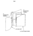
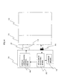
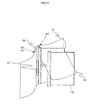
- the invention comprises following means in order to achieve the above object, that is to say, the invention depends on an electronic paper file comprising an electronic paper 10 and a main unit 20 as shown in Figs. 1, 2 and 34.
- the electronic paper 10 is a flexible display medium like paper.
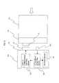
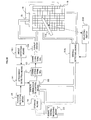
- the main unit 20 provides a display 11 of this electronic paper 10 with display luminescence control means 22 for displaying display data obtained from signal sending-receiving means 23 (23a and 23b shown in Fig. 6).
- the electronic paper may be provided with storage means 60 for storing the display data.
- the connecting terminal 13 of the electronic paper is the female type and the connecting terminal 21 of the main unit 20 is the male type, thereby even in case of carrying the electronic paper 10 detached from the main unit 20 the connecting terminal 13 of the electronic paper can be prevented from the damages and rust.
- the display luminescence control means 22 executes the displaying for the connecting terminal 21 of the main unit to which the electronic paper 10 is not attached.
- the electronic paper file is provided with attachment detecting means 30 for detecting the condition whether the electronic paper 10 is attached to the connecting terminal 21 of the main unit or not. According to the condition of attachment, the display luminescence control means 22 performs the display processing. According to this configuration, it is possible to perform the display processing only for the connecting terminal to which the electronic paper is attached.
- the electronic paper file adopts the following configuration to display the display data on the electronic paper file in the order of pages of the electronic paper file.
- the main unit 20 is provided with storage means 19 for storing the connecting terminal number based on the arrangement position of the connecting terminal.
- the display luminescence control means 22 is to perform the displaying.
- the display luminescence control means is to perform the displaying based on the rotation position of the connecting terminal 21 detected by the position detecting means 30 and the condition of attachment.
- the connecting terminal 13 of the electronic paper must be arranged on the position corresponding to the each connecting terminal 21. Therefore, adopting the following configuration makes possible to connect the connecting terminal 21 of the main unit with the connecting terminal 13 of the electronic paper independently of the position of the connecting terminal 21 of the main unit.
- the electronic paper 10 is provided with a plurality of parallel leads in parallel with the end side.
- the connecting terminal 21 of the main unit is provided with holding plates 41 for holding the electronic paper 10 from both the backside and front side.
- the internal surface of the holding plate is provided with conducting leads 42 of which top contacts to the each parallel lead 40 and as much as the number of leads 40 of the electronic paper.
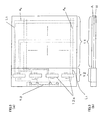
- the display 11 of the electronic paper 10 is provided with a display layer A comprising the nonvolatile display medium possible to perform the pattern display, as shown in Fig. 3. According such configuration, the display data is displayed on the nonvolatile display medium, and in result the electronic paper detached from the main unit 20 can retain the display content.
- the display 11 of the electronic paper 10 is configured to be provided with a luminescence layer B for illuminating the display layer A, it is possible to confirm the display content of the electronic paper 10 in the dark.
- the main unit 20 of the electronic paper file may be provided with display luminescence control means 22 for controlling the luminescence layer B so as to illuminate only a specific area of the display layer A. According to this configuration, it is possible to illuminate only the area that the user wants to emphasize, such as a title area. And if the display luminescence control means 22 is also arranged to control the emitting area of the luminescence layer B, the area to be illuminated can be changed.
- the display luminescence control means 22 may make the luminescence layer B luminous.
- the display luminescence control means 22 may comprises display control means 22a for controlling the display of the display data on the electronic paper and luminescence control means 22b for controlling the luminescence layer B so as to illuminate only the specific area of the display layer A.
- the luminescence control means 22b may make the luminescence layer B luminesce when the power is applied to the electronic paper or when a switch fitted to the main unit physically is pushed by the user.
- the data to be displayed on the electronic paper is the one transmitted from the external of the electronic paper file or the one stored in the storage means 60, but the electronic paper can be configured to display on the electronic paper the data that the user direct writes into the electronic paper.
- the electronic paper 10 is configured that the voltage corresponding to the writing (the deleting) can be impressed per pixel, thereby the user should write or delete the data on the electronic paper with an electronic pen 114.
- either a column or a line electrode per pixel arranged on the back of the front side of the display is connected one after another through contact electrodes arranged per pixel on the front of the front side of the display and switch means 101.
- the electronic paper 10 is provided with a control line 104 for controlling the switch means 101.
- the invention is configured to comprise writing detecting means 105 for detecting that the electronic pen contacts to the contact electrode, extracting the written data and transferring the data to the storage means 60.
- the electronic paper 10 on which the digitizer overlaps can be detected by the rotation angle of the digitizer 15 and the main unit 20.
- characters and graphics that are illustrated physically on the electronic paper with ink can be converted to the data to be displayed on the electronic paper by reading the condition of the electronic paper with the scanner and so on.
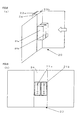
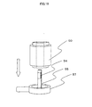
- Fig. 1 is a perspective view showing the configuration of the invention.
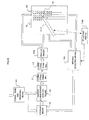
- Fig. 34 is a block diagram showing the electrical configuration of the invention.
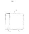
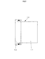
- Fig. 2 and Fig. 3 are conceptual diagrams showing particulars of the electronic paper.
- the electronic paper 10 applying the invention comprises a display 11 that is an area for displaying data, and a display driver unit 12 (a data non-display area) for driving the display 11.
- the display 11 comprises a display layer A provided with a nonvolatile display medium and a luminescence layer B for illuminating the display layer A.
- a column electrode A 3 is formed on an upper base film A 2 , meanwhile, a line electrode A 5 is formed on the lower base film A 6 as shown in Fig. 4.
- a ferroelectric high polymer liquid crystal A 4 specific thick is applied to this line electrode A 5 .
- the column electrode A 3 is pasted to the line electrode A 5 so as to come face to face each other and be in a form of the matrix.
- these layers are held and bonded with deflection plates A 1 and A 7 from both sides.
- the display layer A is formed, which comprises pixels formed in the matrix of Cmax columns and Rmax lines. It is needless to say that the positions of the line electrode and column electrode can be exchanged mutually.
- the luminescence layer B is formed as follows: a transparent common electrode (anode) B 2 is formed on the upper base film B 1 and a metal common electrode (cathode) B 5 is formed on the lower base film B 6 .
- a transparent common electrode (anode) B 2 is formed on the upper base film B 1 and a metal common electrode (cathode) B 5 is formed on the lower base film B 6 .
- an organic electro luminescence layer B 4 is formed in a specific pattern on the common electrode B 5 .
- the common electrode B 2 is pasted to the common electrode B 5 so as to come face to face each other.
- the luminescence layer B thus formed is pasted to the downside of the display layer A so that the luminescence layer B may illuminate the display layer A.
- the ON and OFF of pixels on the above-mentioned display sheet shall be controlled by the matrix control utilizing the shutter function explained as follows. That is to say, when a specific voltage is impressed between the line electrode A 5 and column electrode A 3 of the display layer A, the molecules of ferroelectric high polymer liquid crystal A 4 changes the orientation to the direction not passing the light emitted from the luminescence layer (which means that the shutter is ON), and thereby the pixels specified by the line electrode A 5 and the column electrode A 3 are displayed in black. On the other hand, when the reverse voltage to the above specific voltage is impressed, the molecules of the ferroelectric high polymer liquid crystal A 4 changes the orientation to the direction passing the light (which means that the shutter is OFF), and thereby those pixels are displayed in white.
- the displaying condition of the ferroelectric high polymer liquid crystal A 4 will not change even when the power is cut off. Therefore, even where the specific voltage is not impressed between the line electrode and the column electrode after the electronic paper 10 is detached from the main unit 20, it is possible to retain the display content.
- the whole area of the organic electro luminescence layer B 4 emits light and illuminates the display layer A from the downside. That is to say, where the organic electro luminescence layer B 4 emits the light, the pixels, which allow the light to pass through (of which shutter are OFF), are displayed in black.
- the luminescence layer B depends on the premise that the whole area of it emits light simultaneously, and for this purpose both of the upper and lower electrodes are the common electrodes.
- both of the upper and lower electrodes are the common electrodes.
- the upper and lower common electrodes B 2 and B 5 may be arranged in the form of matrix and can be controlled so as to illuminate only a specific part of the display layer A, it becomes possible to display (or emphasize) title parts only, for example.
- a monochromatic electro luminescence layer may be formed evenly allover the whole area on the luminescence layer as described above.
- RGB Red, Green, Blue
- RGB Red, Green, Blue
- Either one surface of the base films A 2 or A 6 of the display layer A or the base film B 1 of the luminescence layer B is preferable to be rough. Under such arrangement, it is possible to provide the display gentle with eyes because the light emitted from the organic electro luminescence layer B 4 is dispersed by a rough surface S as shown in Fig. 11.
- the line electrodes A 5 and the column electrode A 3 or the common electrodes B 2 and B 5 those comprising respective layers, must be connected previously with display luminescence control means 23 provided to the main unit 20 or the power.
- display luminescence control means 23 provided to the main unit 20 or the power.
- a user wants to detach a desired electronic paper 10 from the main unit 20 in the same way of detaching only a desired page from a loose-leaf type of paper book.
- the invention comprises an arrangement that the electronic paper 10 and the main unit 20 configured as above can be attached and detached physically and electrically.
- the invention is arranged as shown in Fig. 1 so that a connecting terminal 13 (a female type in this case) may be fitted to one side of the display driver unit 12 of the electronic paper 10, and the other connecting terminal 21 (a male type in this case) may be fitted to a side of the main unit 20.
- the invention is arranged that the connecting terminal 13 of the electronic paper 10 be the female type and the connecting terminal 21 of the main unit 20 be the male type. This is for preventing the connecting terminal 13 of the electronic paper from the damage and rust.
- the connecting terminal 13a is required to have pins as much as the number of Cmax+Rmax (the connecting terminal 21 provided with pin receivers as much as the number of Cmax+Rmax).
- the connecting terminal 13 provided with many pins is easy to damage.
- such type is not preferable as seen from the point of view that the electronic paper should be thin and lightweight.
- the invention is arranged as shown in Fig. 3(a) so as to reduce the number of pins of the connecting terminal by incorporating the display driver 12a, which is used for the general LCD display device, between the connecting terminal 13 of the electronic paper 10 and the display 11 (namely, into the display driver unit 12), which will be described later.
- the thickness of the display driver unit 12 may increase more than that of the display 11 and the material used for the display driver unit 12 has the Young's modulus more than that of the display 11. Thereby, it makes possible to protect the display driver 12a comprising the semiconductor chip.
- the connecting terminal 13a of the electronic paper 10 can be attached to the connecting terminal 21a of the main unit 20 without failure in a simple way like pushing the display driver unit 12 from the direction indicated by the arrow 1 ⁇ with finger as shown in Fig. 5.
- display luminescence control means 22 installed in a spine 24 of the main unit 20
- display luminescence control means comprises display control means 22a and luminescence control means 22b, and these two means may be formed in a unit or separately).
- the display luminescence control means 22 may make the luminescence layer B radiate when the power of the electronic paper file is ON or when a user presses down a key for instructing the display.
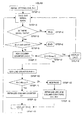
- the display luminescence control means 22 judges whether the data for 1 bit obtained from the signal sending-receiving means 23 is the end data ("EOF", for example) or not. If it is determined to be the end data, the display processing is terminated (Fig. 10, Step S2 to S3 to S5 to S6). Even when the data for 1 bit is not obtained from the signal sending-receiving means 23, the display luminescence control means 22 terminates the display processing by determining that there is no serial data (Fig. 10, Step S3 to S4).
- EAF end data
- the display luminescence control means 22 adds "1" to the column counter (C) and then judges whether the column counter (C) is less than the maximum column number Cmax or not (Fig. 10, Step S7 to S8). In result, if it is determined to be less than the maximum column number Cmax, the processing for displaying the pixel specified by the current line counter (R) and column counter (C) is executed based on the data content for 1 bit (black or white) (fig. 10, Step S8: Yes to Step S9).
- the display luminescence control means 22 gives to the display driver 12a the display data comprising the address data [1,1] and ON meaning the instruction to impress the positive voltage as specific bits of data (8 bits, for example).
- the display driver 12a decodes the display data and impresses the positive voltage on the line electrode A 5 and the column electrode A 2 corresponding to the address data [1,1] (more properly, impresses the positive voltage on the line electrode A 5 through a line wiring L 1 and on the column electrode A 2 through a column wiring L 2 ). Therefore, the pixel specified by the address data [1,1] (which will be called “pixel [1,1]” hereafter) gets to be displayed in black.
- the display luminescence control means 22 sets OFF to the display data, said OFF means the instruction to impress the reverse voltage.
- the display driver 12a impresses the reverse voltage on the line wiring L 1 and column wiring L 2 corresponding to the address data [1,1]. Therefore, the pixel [1,1] gets to be displayed in white.
- the information to be set to the display data may be satisfied with "ON" and "OFF” as mentioned above.
- the digitizer executes the processing of writing additional matters into the display layer A or correcting the content written in advance, (said processing will be described later)
- there is no need to have access to pixels not to be corrected which means it is not necessary to impress the positive voltage nor the reverse voltage.
- the display data of the pixel not to have access is set to a code ("10", for example) meaning NON in order not to activate the display driver 12a.
- the display luminescence control means 22 adds "1" to the line counter (R) (Fig. 10, Step S8: No to Step S10). Besides, those display data of pixels [1,2], [1,3], ...[1, Cmax] on the first line are gives in serial to the display driver 12a following to the display data of the pixel [1,1].
- the display luminescence control means 22 executes the processing for displaying the pixels of line specified by the line counter (R) (fig. 10, Step S11: Yes to S13 to S15 to S2). And when the line counter (R) is over the maximum line number Rmax, the display luminescence control means 22 executes the processing of turning a new page (fig. 10, Step S11: No to S12). Besides, in case of the new page, the line counter (R) and column counter (C) are initialized (Fig. 10, Step S14).
- the invention in this embodiment is based on the assumption that the display data received from the signal sending-receiving means 23 is the binary dot data. However, if said data is the other type like the ASCII format or the binary format, the display luminescence control means 22 is arranged to convert the data to the dot data.
- the signal sending-receiving means 23 is the means for receiving the display data, to be more precise, a driver 23a for reading a signal storage medium like the flash card or the smart media, or a connector 23b like the serial port, the parallel port, or RS-232C for inputting external signals direct to the electronic paper through the cable (or through storage means 60 for storing the data) or the like.
- the invention uses the ferroelectric high polymer liquid crystal A 4 as the nonvolatile display medium, and the nonvolatile display medium may be the electrophoresis microcapsule, the conductive toner or the like.
- main unit 20 may be configured to make enables to execute the abovementioned various controls, and it is not restricted to the configuration shown in Fig. 6.
- Fig. 6 shows as an example the configuration that the connecting terminals 21a and 21b corresponding to a plurality of electronic papers 10 line up sideways, but the connecting terminals 21a and 21b may overlap in the vertical direction as shown in Fig. 8(a). According to such overlapping structure, it is possible to provide more electronic papers 10. In this case, it is needless to say that the connecting terminals 13a and 13b on the side of the electronic paper 10 may be configured so as to overlap in the vertical direction, too.
- the electronic paper 10 of the invention can be detached from the main unit 20. Where the data is sent to the electronic paper thus detached, the data is lost.
- following attachment detecting means 30 may be installed in the main unit 20 so that the display data can be transferred only to the connecting terminal 21 to which the electronic paper 10 is attached.
- the connecting terminal 21 of the main unit 20, of which position is fixed, is disposed on the main body, as shown in Fig. 12.
- the storage means 19 stores the number of each connecting terminal 21 of the main unit (which is called a connecting terminal No. hereinafter) on the basis of the arrangement order.
- the attachment detecting means 30 detects the connecting terminal to which the electronic paper is attached (which will be described later), obtains the connecting terminal number of the connecting terminal 21 thus detected, and notifies the display luminescence control means 22 of said number.
- the connecting terminal number noted here is given as follows.
- the connecting terminal 21 nearest to the front board 31 (though either of the front or back board can be applied, the invention applies the front board) of the electronic paper file shown in Fig. 16 is given "1", and the following connecting terminal numbers increases as gone away from the front board 31.
- the storage means 19 has been installed in the main unit 20. According to this arrangement, the display luminescence control means 22 transfers the display data to the informed connecting terminal number, thereby it is possible to prevent the transfer of the display data to the connecting terminal to which the electronic paper is not connected (specifically, the display leak).
- the following is an example of the configuration that the connecting terminal 21 to which the electronic paper 10 is attached is detected by the attachment detecting means 30.
- the main unit 20 is provided with the attachment detecting means 30 as shown in Fig. 12, and the attachment detecting means 30 outputs two signals of "1" to each connecting terminal 21.
- the two "1" signals are inputted to AND gate 33 of the display driver unit 12 through the connecting terminal 13 of the electronic paper.
- the AND gate 33 returns the "1" signals to the attachment detecting means 30 through the connecting terminals 13 and 21.
- the attachment detecting means 30 detects the electronic paper 10 is attached to the connecting terminal 21 of the output end of the electric signals.
- an internal surface of the spine 24 of the main unit 20 is provided with a push button 34 as shown in Fig. 13. Specifically, at the moment that the connecting terminal 13 of the electronic paper 10 is attached to the specific connecting terminal 21 of the main unit, the push button is to be pushed by the electronic paper 10. Where the push button 34 is pushed down in such way, the attachment detecting means 30 detects the electronic paper 10 is attached to the specific connecting terminal 21.
- the main unit is equipped with a photocoupler 35 for emitting light toward the projected direction of connecting terminal 21 of the main unit.
- the photocoupler may be arranged so as to reflect the light when the electronic paper 10 is attached. According to the reflected light, the attachment detecting means 30 may detect whether the electronic paper 10 is attached or detached.
- the attachment detecting means 30 detects the electronic paper 10 is attached to the connecting terminal 21.
- the above description relates the configuration as shown in Fig. 6 that the connecting terminal 21 of the main unit is placed on the spine 24 directly and both the plane and rotation positions are fixed, however, if the connecting terminal 21 can be rotated, it makes possible to facilitate the handling like the operation of turning over pages.
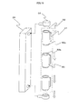
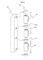
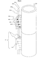
- Fig. 15 shows the structure wherein the connecting terminal 21 can be rotated.
- the upper and lower ends of a rotatable axis part 50 which is a specific length in a cylindrical shape, are provided with inserting parts 50a and 50b that can be connected mutually with the upper and lower ends of the other rotatable axis part 50.
- a reflecting part 53 is illustrated so that the width may increase gradually in the circumferential direction.
- the axis direction of the external of the rotatable axis part 50 is provided with the connecting terminal 21 of the main unit.
- the rotatable axis parts 50 configured in this way are connected each other, thereby a coupling axis 52 can be formed.
- the photocoupler 54 is fixed to an element fixed axis 55 in each rotatable axis part 50 at the position corresponding to the reflecting part 53 as shown in Fig. 17.
- the element fixed axis 55 is inserted to the copling axis 52 and fixed the both end to axis end parts 56.
- This axis end part 56 is provided with the upper and lower ends of the coupling axis 52 rotatably. And the axis end part 56 is fixed to the inside of the spine 24.
- Various means can be considered for fixing the axis end part 56 to the inside of the spine 24 and for fixing the both ends of the element fixed axis 55 to the both ends of the axis end part 56, however, these means are not essential parts of the invention and will not be explained here.
- each photocoupler 54 is arranged to emit light in the same one direction.
- the connecting terminals 21 attached to each movable part 50 are in a same direction
- the reflecting part 53 illustrated on the internal surface of each connecting terminal is arranged to indicate the same width in the axis direction along with the internal surface of the circumference. Therefore, the photocoupler 54 is to output the signals corresponding to the rotation angle of each rotatable axis 50, namely, the rotation angle of each electronic paper 10.
- each rotatable axis 50 is connected directly each other, but it is possible to fix the coupling axis 52 to the spine 24 more stably by intervene an intermediate fixed part 57 between rotatable axis parts 50 as shown in Fig. 18.
- each rotatable axis part are inserted into the intermediate fixed part 57 rotatably, to which each rotatable axis part 50 is jointed.
- the coupling axis 52 can be formed. Both ends of the coupling axis 52 configured in such way are fixed to the spine 24 by means of the axis end part 56 in the same way as above.
- the coupling axis 52 is also fixed to the spine 24 by means of the intermediate fixed part 57.
- the element fixed axis 55 may be fixed by the axis end parts 56 of the both ends like the above example. Furthermore, it may be arranged as shown in Fig. 19 that the element fixed axis 55 for setting the photocoupler 54 may project from each intermediate fixed part 57 (or the end part 56) into the inside of each rotatable axis part 50.
- a variable resistor 70 may be used as a substitute for the photocoupler 54. That is to say, in order not to prevent the rotation of the rotatable axis part 50, the variable resistor 70 in doughnut shape is fixed to the element fixed axis 55. And the internal surface of each rotatable axis part 50 is provided with a movable terminal 71 in contact with the variable resistor 70. In this case, where each connecting terminal 21 are oriented toward a same direction, the each variable resistor 70 is to output a same value. Thereby, it is possible to obtain the rotation angle of each electronic paper.
- the position detecting means 36 of the main unit 20 notifies the attachment detecting means 30 of the rotation angle of each connecting terminal obtained from the photocoupler 54 or the variable resistor 70.
- the attachment detecting means 30 detects the connecting terminal 21 to which the electronic paper 10 attached, and then on the basis of the above notification assigns the connecting terminal number to the detected connecting terminal 21.
- the connecting terminal number noted here is given as follows.
- the connecting terminal 21 nearest to the front board 31 of the electronic paper file is given "1", and the following connecting terminal numbers increases as gone away from the front board 31.
- the attachment detecting means 30 notifies the display luminescence control means 22 of the connecting terminal number.
- the display luminescence control means 22 performs the displaying as above in the order of the connecting terminal number. Therefore, the display data gets to be displayed in the order of page.
- the connecting terminal 13 of the electronic paper 10 described above is fixed to a specific position of the electronic paper 10. Accordingly, the electronic paper 10 can be attached only to the connecting terminal 21 of the main unit of which position is corresponding to the connecting terminal 13. That is to say, where a plurality of connecting terminal 21 are laid at positions different each other in the vertical direction of the main unit 20 as shown in Figs. 21(a) and 21(b), there is a problem that the electronic paper 10 must be provided with the connecting terminal 13 of which position is connectable with each connecting terminal 21 of the main unit 20. Consequently, in order to attach the electronic paper 10 to the electronic paper file independently of the position of the connecting terminal 21, the invention may adopt the following arrangement.
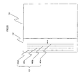
- the end side of the electronic paper 10 is provide with leads 40 (40a, 40b,%) as much as the number necessary for transferring the display data, which is formed in parallel each other in the vertical direction as the connecting terminal 13 of the electronic paper 10.
- a pair of holding plates 41 may be arranged so as to project from the rotatable axis part 50 in the radial direction of the rotatable axis part 50 as shown in Fig. 23, the holding plate 41 for holding elastically the electronic paper in the direction of the thickness of the electronic paper.
- the internal surface of the holding plate 41 is provided with conducting leads 42 so that the top of the conducting lead may contact with each of the lead 40 provided on the electronic paper 10.
- the conducting lead 42 is to be conducted into the inside of the main unit.
- the number of the conducting leads 42 (42a, 42b, ...) composing each connecting terminal 21 is as much as the number of the reads 40 of the electronic paper.
- the conducting lead 42 is provided with a contact point 43 of which top only can be in contact with the read 40 electrically.
- each leads 40a, 40b, ... came in contact with each contact point 43a, 43b, ....
- the display data transferred by the display luminescence control means 22 runs to the electronic paper through the contacting points 43a, 43b, ... and each lead 40a, 40b, ....
- the connecting terminal number of the connecting terminal to which the electronic paper 10 is attached may be displayed on the electronic paper. In this way, if the connecting terminal number is displayed on the electronic paper, even after this electronic paper is detached from the main unit 20, it is easy for the user to know the order of the display data displayed on the electronic paper 10 by having a look at the connecting terminal number.
- the attachment detecting means 30 has been set to always detect the attachment of the electronic paper 10. That is to say, at the time of detecting that the electronic paper 10 is attached to the connecting terminal 21 or detached from the connecting terminal 21, the attachment detecting means 30 notifies the display luminescence control means 22 of the connecting terminal number of the connecting terminal 21 to which the electronic paper 10 is attached as mentioned above. Additionally, if the main unit 20 is provided with the position detecting means 36, the position detecting means 36, in conjunction with the attachment detecting means 30, assign the connecting terminal number to the connecting terminal 21 as mentioned above, and then notifies the display luminescence control means 22 of the connecting terminal number.
- the display luminescence control means 22 reads the display data from the storage means 60, and then performs the displaying on the basis of the notified connecting terminal number.
- the main unit 20 is not provided with the storage means 60 and is provided with it.
- the electronic paper 10 can be configured to be provided with the storage means for storing the data.
- the display luminescence control means 22 might be arranged to obtain the display data from the storage means and then performs the displaying as above.
- the main unit 20 is provided with a specific button.
- the attachment detecting means 30 or the position detecting means 36 may be activated when the user pushes this button. And when the power of the electronic paper file is ON or when the display of the electronic paper is cleared temporarily, the attachment detecting means 30 or the position detecting means 36 may be activated automatically.
- the display data contains the luminescence control data.
- the display luminescence control means 22 or the luminescence control means 22b is to perform the luminescence control.
- the electronic paper 10 may be connected with the main unit 20 electrically.
- the connecting method the wireless (IRDA, etc) method may be applied, for example.
- the electronic paper 10 and the main unit 20 must be provided with communication means permitting the wireless connection.
- the embodiment of the invention can allow the electronic paper to be detached from the main unit and to retain the display content. And according to the configuration provided with the luminescence layer, it is possible to confirm the display content of the electronic paper even in the dark.
- the invention uses the nonvolatile display medium (the ferroelectric high polymer liquid crystal) as the display medium.
- the nonvolatile display medium the ferroelectric high polymer liquid crystal
- the configuration of the display can be simplified. In result, there is an effect that can provide for reducing the thickness and price and saving the weight of the electronic paper.
- Storing the connecting terminal number in the storage means 19 of the main unit can prevent the display leak of the display data and can display the display data in the page order of the electronic paper file.
- the display luminescence control means 22 is to display the data transmitted from the external or the data stored in the storage medium. Additionally, using the following writing means makes possible that the user be free to write his desired description into the electronic paper 10 or delete his desired description from the electronic paper 10.
- the column electrode A 3 arranged on the back of the base film A 2 on the front side of the electronic paper is led to the surface of a deflection plate A 1 through a through-hole 100 while being corresponding to each pixel.
- the column electrode A 3 led in such way is connected with an end of switch means 101 through the lead 103 (a contact electrode). And then it is led again to the backside of the base film A 2 from the other end of this switch means 101 through the lead 104 and the through-hole 100.
- the switch means 101 is inserted between the pixels neighboring in the column direction. Therefore, when all the switch means 101 is turned ON, the contact electrode forms a primary column. When the switch means 101 is turned OFF, the contact electrode forms an electrode unique in a specific pixel.
- a control line 104 is arranged on the deflection plate A 1 so that the display luminescence control means 22 can turn the group of the switch means 101 on or off according to the purpose.
- the display processing will function well under the above configuration.
- the lead is led from a back end of an electronic pen 114 that is provided with a contact marker 118 at the top end.
- the lead is connected with the line electrode A5 of the electronic paper in common. Between the contact marker 118 of the electronic pen 114 and the lead a power is installed.
- the group of the switch means 104 has been turned ON.
- each switch means has been turned OFF.
- the top of the electronic pen 114 be in contact with the lead (the contact electrode) 103 led to the surface of the deflection plate A 1 as above.
- the voltage is impressed between the line electrode A 5 forming the common electrode and the position of the common electrode A 3 corresponding to the lead 103 contacting with the contact marker 118 of the electronic pen 114, and then it is possible to write in the pixel.
- the voltage reverse to the voltage at the writing should be impressed at the deletion.
- the electronic pen 114 is provided with selecting means 106 at the specific position, and only by operating this selecting means 106, it is possible to select "the writing" or "the deleting” easily.
- the selecting means 106 is a switch or the like that enables the contact marker 118 of the electronic pen 114 to change to either of the positive or reverse voltage.
- the electronic paper 10 is provided with a switch for impressing the reverse voltage on the whole area of the display layer A of the electronic paper 10, it is possible to delete the data on the display layer A in block.
- the above-mentioned configuration merely denotes a configuration wherein it is possible to direct write in or delete from the electronic paper.
- the following processing must be taken.
- connection between the lead of the electronic pen 10 and the line electrode A 5 is exchanged from an upper line to a lower line at a pace far speeder than the manual movement of the electric pen 10.
- it must be detected every line the position with which the contact marker 118 of the electronic pen 10 is in contact.
- it is arranged to detect every column through the control line 104 or the other separated detecting line that the contact marker 118 of the electronic pen 114 is in contact with the lead 104 on the deflection plate A 1 .
- a detecting signal Sl per line and a detecting signal Sr per column are inputted into writing detecting means 105.
- the writing detecting means 105 detects the writing position (the deleting position), and judges based on a selecting signal from the selecting means 106 whether the instruction is the writing or the deleting. Consequently, the data to be stored in the storage means 60 is prepared, and according to thus prepared data the content of the storage means 60 is to be updated.
- the displaying of the electronic paper 10 itself is to be performed according to the voltage impressed by the electronic pen 114.
- the display control means 22 or the storage means 60 need to recognize which electronic paper 10 is to be an object of the update.
- the control line 104 may confirm the electronic paper 10 of which switch means 101 is turned OFF.
- the electronic paper of the invention enables the electronic pen of the writing means to perform the writing or the deleting directly on the nonvolatile display medium of the display layer of the electronic paper, even when the electronic paper is not connected with the power.
- the electronic paper is configured to be suited for performing the direct writing.
- the digitizer applied to the configuration of the conventional display device is fitted to the electronic paper, and the electronic paper is configured that the writing (the deleting) can be performed according to the position signal outputted from the digitizer.
- the digitizer it is possible to perform the writing or the deleting in relative easy.
- installing the digitizer in each electronic paper might increase the cost of the electronic paper. Consequently, the following configuration is possible to put the function of the digitizer to effective use.
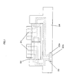
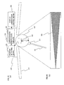
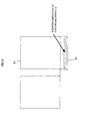
- Fig. 27 is a diagram showing the configuration that the writing means comprises a sheet including the digitizer function and a writing material.
- Fig. 28 is the block diagram. It is arranged that the digitizer can detect the position to which the writing material contacts and the display 11 can be looked through the sheet with overlapping the sheet on the display 11.
- a transparent sheet 15 including the digitizer function is arranged as shown in Fig. 27 that the upper end side is fixed to a back cover 32 of the main unit 20.
- the connection of the transparent sheet 15 and the main unit 20 may be the detachable type using the connecting terminal or the wireless type, instead of the above fixed type. But, in order to specify the electronic paper 10 to be an object of the writing, it is preferable to configure that the electronic paper file can detect the rotation angle (which will be described later).
- the electronic paper 10 is fitted to the main unit 20, and overlapped on the back cover 32 of the main unit 20. After that, the transparent sheet 15 is placed on the electronic paper 10. In addition, where there is a plurality of electronic papers 10, the transparent sheet 15 is placed on the electronic paper 10 of the facing page.
- the display luminescence control means 22 (in case of displaying the data stored in the storage medium 60, the storage means 60 and the display luminescence control means 22) has to recognize the electronic page the transparent page is placed on.
- the electronic paper file is provided with the position detecting means 36 for detecting the rotation angle as explained in the embodiment 1, it is possible to specify the page having the angle of almost 180 degree with the neighboring page as an object page of the writing.
- the display luminescence control means 22 could not know either a step for writing into the electronic paper by means of the transparent sheet 15 or a step for writing into the electronic paper the data sent from the signal sending-receiving means 23 (or the storage means 60). Therefore, as shown in Fig. 30 (likewise the configuration of Fig.
- the attachment detecting means is to recognize that the transparent sheet 15 is placed on the facing page.
- attachment detecting means 30 knows the order of the connecting terminal 21 as shown in Figs. 16 and 20, according to this order it is possible to know the sheet on which the transparent sheet is placed.
- facing page detecting means 153 is required, as shown in Fig. 29, in order to detect whether the each page are contacted or separated. According to the facing page detected by the facing page detecting means 153, the arrangement order of the connecting terminal 21 stored in the storage means 19 and the output of the angle detecting means 151, it is possible to detect the page that the digitizer 15 is placed on.
- the transparent sheet 15 transfers the position information corresponding to the contact position toward the writing detecting means 205.
- the writing detecting means 205 prepares the corresponding display data and gives it to the display luminescence control means 22.
- the display luminescence control means 22 is to transfer the signal from the writing detecting means 205 toward the electronic paper 10.
- the data transmitted from the writing detecting means 205 is also transmitted to the storage means 60. Thereby, the content stored in the storage means is to be updated.
- the electronic paper in this embodiment of the invention can perform the partial writing and deleting by means of the writing means comprising the transparent sheet including the digitizer function and the control means of the electronic paper file.
- the writing means comprising the transparent sheet including the digitizer function and the control means of the electronic paper file.
- the transparent sheet 15 may be fitted to the front cover of the main unit 20, or to both the front and back covers. And while keeping the connection of the transparent sheet 15 and the display luminescence control means 22, the transparent sheet 15 itself may be free to be fitted to the main unit 20 or the electronic paper 10 mutually, otherwise, may be placed on the electronic paper 10 only when needed. In addition, it may be configured that the transparent sheet 15 be pasted on the electronic paper 10.
- the characters and graphics illustrated physically on the surface of the electronic paper with the writing material can be written into the electronic paper by using a scanner.
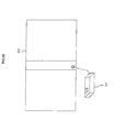
- Fig. 31 shows a case of using a sheetfeed scanner 16
- Fig. 32 shows a case of using a handy scanner 17.
- Fig. 33 shows a simple block diagram of this embodiment of the invention.
- the handy scanner 17 is taken to be connected with the control means 21 of the main unit 20 through cable, and the sheetfeed scanner 16 is taken to be fixed to a specific position of the main unit 20. However, there is nothing but to ensure that the sheetfeed scanner 16 and the handy scanner 17 are electrically connected with the control means 21 of the electronic paper file. As this connecting method, it is possible to use the same way as the connecting method of the electronic paper 10 and the main unit 20 described in the embodiment 1.
- the next step is to read the characters and shapes of graphics on the display layer A together with the positions.
- the overwritten electronic paper 10 is adjusted to a specific position of a slot of the sheetfeed scanner 16 without being attached to the main unit 20. And the electronic paper 10 is passed through the slot from a specific direction, and then the sheet feed scanner 17 reads the characters and shapes of graphics on the display layer A together with the position.
- a specific position of the handy scanner 17 is adjusted to a specific position of the display 11 of the overwritten electronic paper 10. And the handy scanner 17 is moved in a specific direction, and reads the characters and shapes of the graphics on the display layer A together with the position. At this time, the electronic paper 10 needs not to be attached to the main unit 20
- the main unit 20 requires the storage means 220 for storing the data relevant to the characters and shapes of graphics on the display layer A of the electronic paper 10 read by the sheetfeed scanner 16 or the handy scanner 17, together with the position.
- the display luminescence control means 22 displays on the electronic paper the contents read in this way.
- the sheetfeed scanner 16 is to read the entire position information and the character and graphics information displayed on the display layer A of the electronic paper 10.
- the display luminescence control means 22 is to update the display content by writing into the whole of the display layer A the data received from the sheetfeed scanner 16.
- the display luminescence control means 22 has to scan the whole of the display 11. Accordingly, the area of which data is not received from the handy scanner is regarded that there is no data, and since the data before the update is deleted after the update, nothing is to be displayed. This is an inconvenient matter.
- the display luminescence control means 22 transmits to the electronic paper 10 the data of "NON" indicating the instruction not to rewrite the display data 18 relevant to the limited area. Thereby, the data of only the limited area on the display area A is to be outputted, consequently the partial writing can be executed.
Landscapes
- Engineering & Computer Science (AREA)
- Theoretical Computer Science (AREA)
- Computer Hardware Design (AREA)
- Physics & Mathematics (AREA)
- General Physics & Mathematics (AREA)
- Human Computer Interaction (AREA)
- General Engineering & Computer Science (AREA)
- Mathematical Physics (AREA)
- Control Of Indicators Other Than Cathode Ray Tubes (AREA)
Abstract
The invention has an object to provide the
electronic paper file, which an electronic paper can be
attached to or detached from by providing a connecting
terminal including the physical or electrical connecting
function to both the electronic paper and the main unit.
Since the display data is to be displayed on the
nonvolatile display medium fitted to the display of the
electronic paper, the electronic paper detached from the
main unit can retain the display content. Since the
connecting terminal fitted to the main unit is fixed to
the rotatable rotatable axis, it is possible to retain the
desired page with keeping double-pages spread
Description
The invention relates an electronic paper that is
a display medium flexible like paper, and an electronic
paper file comprising a plurality of said electronic
papers bound like the book.
With the advance of the information society, the
performance of the display medium such as CRT (Cathode Ray
Tube), LCD (Liquid Crystal Display) and so on has been
improved rapidly. However, regarding the legibility and
user-facility, such display mediums are not superior to
the "paper" that has been used as an information medium
from a long time ago. Consequently, the "electronic paper"
is proposed as a new concept for the above sheet-like
flexible display medium, and the various technologies have
been studied in order to carry out this electronic paper
(Pages 209 to 251 of "Japan Hardcopy'99 - The Collected
Papers" published by The Imaging Society in Japan).
Additionally, it is also proposed in these days
the electronic paper file filing plural electronic papers
like a book (PCT Japanese translation publication No.11-502950).
With the help of such electronic paper file, it
is possible not only to simplify the management of plural
electronic papers, but also to use the electronic papers
as the more legible and user-facile display medium.
The display medium to be applied to the electronic
paper is a volatile or nonvolatile liquid crystal. In case
of the volatile display medium, the display goes dark when
the electronic paper is cut off from the power. On the
other hand, in case of the nonvolatile display medium, the
displaying content can be kept even when the electronic
paper is cut off from the power. This is beneficial
because the electronic paper can be handled as well as a
sheet. However, after the display content is deleted
temporarily in order to rewrite, a user has to execute the
rewriting. Therefore, it is necessary to select for the
electronic paper the nonvolatile material able to rewrite
the display content easily.
The material of thus rewritable nonvolatile
display medium has been studied in many ways (see pages
209 to 251 of "Japan Hardcopy'99 - The Collected Papers"
published by The Imaging Society in Japan). For instance,
there is the thermosensitive recording type of nonvolatile
display medium wherein the color developing and erasing
are performed by means of the leuco dye and the developer.
This nonvolatile display medium develops colors when it is
heated until the leuco dye and the developer blend. Where
the condition of the color developing cools down gradually,
the color is erased. Meanwhile, when the condition cools
down suddenly, the color developing is fixed; thereby
illustrated images can be retained. That is to say, the
rewriting and the deleting are executed by the heat
control.
In addition, there is a nonvolatile display medium
that is the Guest-Host type adopting the smectic liquid
crystal and the dichronic dye and uses the liquid
crystal/polymer composite film. The nonvolatile display
medium becomes the focal conic state wherein the dichronic
dye is oriented together with the liquid crystal by heat,
thereby the light absorption increases and the display
medium develops colors. And then, by impressing the
electric field on the color-developing display medium, the
focal conic state changes to the homeotropic state, and
then the colors are erased. In other words, the heat is to
rewrite and the electric field is to erase. Besides, one
of the Guest-host types of liquid crystal can develop
colors by the voltage and erase them by the heat.
And there is a nonvolatile display medium adopting
the electrophoresis phenomenon of pigment particles
dispersed in the coloring solvent, which is configured to
encapsulate such dispersion solution in a microcapsule. In
this case, the rewriting and the erasing are executed by
the electric field.
Moreover, there is a nonvolatile display medium
configured so that cells containing the conductive toner
and white corpuscular are filled between a pair of
transparent electrodes. Under this configuration, the
rewriting is performed as follows: the voltage is
impressed between the pair of transparent electrodes,
which moves the conductive toner toward the other
electrode by the clone attractive force. Therefore, in
case of the erasing, the reverse electric field is to be
impressed between the pair of transparent electrodes.
The aforementioned thermosensitive recording type
of nonvolatile display medium using the leuco dye and the
developer performs the rewriting and erasing by heat as
described above. Accordingly, the thermal stylus is used
for the rewriting; meanwhile the thermal eraser utilizing
the infrared lamp is used for the erasing.
The other input device for inputting characters
and graphics into the rewritable display medium is the
digitizer, for example. The digitizer is provided with
wires or printed wires interlaced in lattice-like in the
direction of the orthogonal two axes on the flat plate.
When the pulse is transmitted to the two axes, the
position of the intersection is detected in result of
reading the pulse by an electronic pen or the like;
thereby the input processing is performed. The light pen
is provided at the top with a photo acceptance element.
The photo acceptance element reads the position on the
display, which performs the input processing.
And now, a loose-leaf book or notebook made from
paper has a merit that only a desired page can be removed
and carried on. However, regarding the abovementioned
conventional electronic paper file it is impossible to
remove and carry out only a specific electronic paper
since the electronic paper and the main unit itself (the
front board) controlling the electronic paper are
integrated in one unit.
In addition, where a specific content is displayed
on the electronic paper, it is general that the display
content is the one stored as electronic data in a memory
of the main unit or the one transmitted from an external
memory. For this purpose, it may utilize the volatile
display medium as the display medium of the electronic
paper. However, in order to remove and carry on only the
electronic paper separating from the main unit as
described above, it is necessary for each electronic paper
to maintain the display even in the condition that the
power is cut off. However, in case of using the volatile
display medium as above, when the electronic paper is
removed from the main unit, it becomes impossible to keep
the condition of display.
As mentioned above, the electronic paper is
requested the same portability as the ordinary paper, and
at the same time sometime requested the function to
reflect the handwritten characters and graphics on the
electronic paper or to delete the content inputted from
the memory or written by hand as above.
In this case, on the basis of the conventional art,
each electronic paper must be provided with the digitizer
and receive the position that the user designates on the
digitizer. On the position thus designated, the control
means arranges a specific pixel. However, installing the
digitizer in all the electronic papers respectively causes
the device to be costly.
Moreover, it has been promoted the approach to
render the rewriting and the erasing by the heat or the
electric field, but in case of using the heat there is a
possibility that the medium is damaged and deteriorated by
the heat. In order to cope with this trouble, the
following countermeasures has been studied; the
arrangement that the surface of the medium is provided
with a hard coating layer, the contactless means applying
the laser and so on. However, those have not been in the
practical use.
Where the rewriting and erasing by the electric
field do not depends on using the digitizer, it is
necessary to impress the voltage on the display medium
directly. But it is general that the surface of the liquid
crystal display is not provided with any electrode for
impressing the voltage on the display medium directly.
The present invention is proposed in consideration
of the abovementioned conventional conditions, and has an
object to provide the electronic paper file wherein each
electronic paper of the electronic paper file can be
attached to or detached from the main unit. And the
invention also has another object to provide the
inexpensive electronic paper wherein the user can rewrite
in or delete from the display medium by hand without using
the heat.
The invention comprises following means in order
to achieve the above object, that is to say, the invention
depends on an electronic paper file comprising an
electronic paper 10 and a main unit 20 as shown in Figs. 1,
2 and 34.
The electronic paper 10 is a flexible display
medium like paper. And the main unit 20 provides a display
11 of this electronic paper 10 with display luminescence
control means 22 for displaying display data obtained from
signal sending-receiving means 23 (23a and 23b shown in
Fig. 6). Moreover, the electronic paper may be provided
with storage means 60 for storing the display data.
A pair of a male and female type of connecting
terminals having the physical and electrical connecting
functions, one connecting terminal 13 of which is provided
to a side of the display 11 of the electric paper 10 and
the other connecting terminal 21 of which provided to the
main unit 20, these configuration allows the electronic
paper 10 to be attached to or detached from the main unit
20. At this time, the connecting terminal 13 of the
electronic paper is the female type and the connecting
terminal 21 of the main unit 20 is the male type, thereby
even in case of carrying the electronic paper 10 detached
from the main unit 20 the connecting terminal 13 of the
electronic paper can be prevented from the damages and
rust.
As the configuration for fitting the connecting
terminal 21 of the main unit 20 on the main unit 20, one
is to fix the arrangement position of the connecting
terminal 21 as shown in Figs. 1 and 2, and another is to
provide the rotatable axis part rotatably connected to the
main unit 20 with the connecting terminal 21 as shown in
Fig. 15.
There is a possibility that the display
luminescence control means 22 executes the displaying for
the connecting terminal 21 of the main unit to which the
electronic paper 10 is not attached. In order to settle
this problem, the electronic paper file is provided with
attachment detecting means 30 for detecting the condition
whether the electronic paper 10 is attached to the
connecting terminal 21 of the main unit or not. According
to the condition of attachment, the display luminescence
control means 22 performs the display processing.
According to this configuration, it is possible to perform
the display processing only for the connecting terminal to
which the electronic paper is attached.
In addition, the electronic paper file adopts the
following configuration to display the display data on the
electronic paper file in the order of pages of the
electronic paper file. Specifically, if the arrangement
position of the connecting terminal 21 of the main unit is
fixed to the main unit 20, the main unit 20 is provided
with storage means 19 for storing the connecting terminal
number based on the arrangement position of the connecting
terminal. According to the connecting terminal number and
the condition of attachment, the display luminescence
control means 22 is to perform the displaying. Under the
configuration that the connecting terminal 21 of the main
unit is fitted to a rotatable axis part 50, the display
luminescence control means is to perform the displaying
based on the rotation position of the connecting terminal
21 detected by the position detecting means 30 and the
condition of attachment.
As mentioned above, where two parts of the
connecting terminal 13 of the electronic paper and the
connecting terminal 21 of the main unit make a pair and
the positions to arrange each connecting terminal 21 are
different each other, the connecting terminal 13 of the
electronic paper must be arranged on the position
corresponding to the each connecting terminal 21.
Therefore, adopting the following configuration makes
possible to connect the connecting terminal 21 of the main
unit with the connecting terminal 13 of the electronic
paper independently of the position of the connecting
terminal 21 of the main unit.
In other words, the electronic paper 10 is
provided with a plurality of parallel leads in parallel
with the end side. On the other hand, the connecting
terminal 21 of the main unit is provided with holding
plates 41 for holding the electronic paper 10 from both
the backside and front side. And the internal surface of
the holding plate is provided with conducting leads 42 of
which top contacts to the each parallel lead 40 and as
much as the number of leads 40 of the electronic paper.
Additionally, the display 11 of the electronic
paper 10 is provided with a display layer A comprising the
nonvolatile display medium possible to perform the pattern
display, as shown in Fig. 3. According such configuration,
the display data is displayed on the nonvolatile display
medium, and in result the electronic paper detached from
the main unit 20 can retain the display content.
Moreover, where the display 11 of the electronic
paper 10 is configured to be provided with a luminescence
layer B for illuminating the display layer A, it is
possible to confirm the display content of the electronic
paper 10 in the dark.
Besides, the main unit 20 of the electronic paper
file may be provided with display luminescence control
means 22 for controlling the luminescence layer B so as to
illuminate only a specific area of the display layer A.
According to this configuration, it is possible to
illuminate only the area that the user wants to emphasize,
such as a title area. And if the display luminescence
control means 22 is also arranged to control the emitting
area of the luminescence layer B, the area to be
illuminated can be changed.
Besides, when the power is applied to the
electronic paper or when a physical switch fitted to the
main unit is pushed by the user, the display luminescence
control means 22 may make the luminescence layer B
luminous.
In addition, the display luminescence control
means 22 may comprises display control means 22a for
controlling the display of the display data on the
electronic paper and luminescence control means 22b for
controlling the luminescence layer B so as to illuminate
only the specific area of the display layer A. The
luminescence control means 22b may make the luminescence
layer B luminesce when the power is applied to the
electronic paper or when a switch fitted to the main unit
physically is pushed by the user.
In the above description, the data to be displayed
on the electronic paper is the one transmitted from the
external of the electronic paper file or the one stored in
the storage means 60, but the electronic paper can be
configured to display on the electronic paper the data
that the user direct writes into the electronic paper.
Specifically, the electronic paper 10 is
configured that the voltage corresponding to the writing
(the deleting) can be impressed per pixel, thereby the
user should write or delete the data on the electronic
paper with an electronic pen 114.
In this case, either a column or a line electrode
per pixel arranged on the back of the front side of the
display is connected one after another through contact
electrodes arranged per pixel on the front of the front
side of the display and switch means 101. The electronic
paper 10 is provided with a control line 104 for
controlling the switch means 101.
In case of displaying the data transmitted from
the storage means 60, there is a necessity to reflect the
written or deleted data on the content stored in the
storage means 60. Therefore, the invention is configured
to comprise writing detecting means 105 for detecting that
the electronic pen contacts to the contact electrode,
extracting the written data and transferring the data to
the storage means 60.
As a matter of course, it is possible to write
into (or delete from) the electronic paper by using the
digitizer. In this case, the electronic paper 10 on which
the digitizer overlaps can be detected by the rotation
angle of the digitizer 15 and the main unit 20.
Further more, the characters and graphics that are
illustrated physically on the electronic paper with ink
can be converted to the data to be displayed on the
electronic paper by reading the condition of the
electronic paper with the scanner and so on.
The embodiment of the invention is explained
according to attached drawings.
First of all, the invention in mono color is
explained here in detail. Fig. 1 is a perspective view
showing the configuration of the invention. Fig. 34 is a
block diagram showing the electrical configuration of the
invention. Fig. 2 and Fig. 3 are conceptual diagrams
showing particulars of the electronic paper.
As shown in Figs. 2 and 3, the electronic paper 10
applying the invention comprises a display 11 that is an
area for displaying data, and a display driver unit 12 (a
data non-display area) for driving the display 11. The
display 11 comprises a display layer A provided with a
nonvolatile display medium and a luminescence layer B for
illuminating the display layer A.
That is to say, first a column electrode A3 is
formed on an upper base film A2, meanwhile, a line
electrode A5 is formed on the lower base film A6 as shown
in Fig. 4. Secondarily, a ferroelectric high polymer
liquid crystal A4 specific thick is applied to this line
electrode A5. And thirdly, the column electrode A3 is
pasted to the line electrode A5 so as to come face to face
each other and be in a form of the matrix. In addition,
after molecules of the ferroelectric high polymer liquid
crystal A4 are oriented toward a specific direction, these
layers are held and bonded with deflection plates A1 and A7
from both sides. Thereby, the display layer A is formed,
which comprises pixels formed in the matrix of Cmax
columns and Rmax lines. It is needless to say that the
positions of the line electrode and column electrode can
be exchanged mutually.
In contradiction to this, on the basis that the
whole area of the luminescence layer B may emit a light
equally in the intensity, the luminescence layer B is
formed as follows: a transparent common electrode (anode)
B2 is formed on the upper base film B1 and a metal common
electrode (cathode) B5 is formed on the lower base film B6.
By means of an insulating layer B3, an organic electro
luminescence layer B4 is formed in a specific pattern on
the common electrode B5. After that, the common electrode
B2 is pasted to the common electrode B5 so as to come face
to face each other.
In the last place, the luminescence layer B thus
formed is pasted to the downside of the display layer A so
that the luminescence layer B may illuminate the display
layer A.
The ON and OFF of pixels on the above-mentioned
display sheet shall be controlled by the matrix control
utilizing the shutter function explained as follows. That
is to say, when a specific voltage is impressed between
the line electrode A5 and column electrode A3 of the
display layer A, the molecules of ferroelectric high
polymer liquid crystal A4 changes the orientation to the
direction not passing the light emitted from the
luminescence layer (which means that the shutter is ON),
and thereby the pixels specified by the line electrode A5
and the column electrode A3 are displayed in black. On the
other hand, when the reverse voltage to the above specific
voltage is impressed, the molecules of the ferroelectric
high polymer liquid crystal A4 changes the orientation to
the direction passing the light (which means that the
shutter is OFF), and thereby those pixels are displayed in
white.
Besides, the displaying condition of the
ferroelectric high polymer liquid crystal A4 will not
change even when the power is cut off. Therefore, even
where the specific voltage is not impressed between the
line electrode and the column electrode after the
electronic paper 10 is detached from the main unit 20, it
is possible to retain the display content.
On the other hand, when the voltage is impressed
between the common electrodes B2 and B5 of the
luminescence layer B, the whole area of the organic
electro luminescence layer B4 emits light and illuminates
the display layer A from the downside. That is to say,
where the organic electro luminescence layer B4 emits the
light, the pixels, which allow the light to pass through
(of which shutter are OFF), are displayed in black.
Besides, the luminescence layer B depends on the
premise that the whole area of it emits light
simultaneously, and for this purpose both of the upper and
lower electrodes are the common electrodes. However, where
the upper and lower common electrodes B2 and B5 may be
arranged in the form of matrix and can be controlled so as
to illuminate only a specific part of the display layer A,
it becomes possible to display (or emphasize) title parts
only, for example.
Additionally, in case of making the luminescence
layer B luminesces in mono-color, a monochromatic electro
luminescence layer may be formed evenly allover the whole
area on the luminescence layer as described above. On the
contrary, in case of making the layer B luminesces in
full-color, RGB (Red, Green, Blue) light sources may be
formed in matrix on the luminescence layer B. In case of
making the whole area luminesces even in full-color, it is
not necessary that the electrode should be formed in
matrix as described above, but it is sufficient to make
RGB electro luminescence layer radiate simultaneously by
means of the common electrodes B2 and B5.
Either one surface of the base films A2 or A6 of
the display layer A or the base film B1 of the luminescence
layer B is preferable to be rough. Under such arrangement,
it is possible to provide the display gentle with eyes
because the light emitted from the organic electro
luminescence layer B4 is dispersed by a rough surface S as
shown in Fig. 11.
In order to impress the voltage on the display
layer A and the luminescence layer B or to control the
display as described above, the line electrodes A5 and the
column electrode A3 or the common electrodes B2 and B5,
those comprising respective layers, must be connected
previously with display luminescence control means 23
provided to the main unit 20 or the power. On the other
hand, there is a case where a user wants to detach a
desired electronic paper 10 from the main unit 20 in the
same way of detaching only a desired page from a loose-leaf
type of paper book.
Therefore, the invention comprises an arrangement
that the electronic paper 10 and the main unit 20
configured as above can be attached and detached
physically and electrically.
That is to say, the invention is arranged as shown
in Fig. 1 so that a connecting terminal 13 (a female type
in this case) may be fitted to one side of the display
driver unit 12 of the electronic paper 10, and the other
connecting terminal 21 (a male type in this case) may be
fitted to a side of the main unit 20. In such way, the
invention is arranged that the connecting terminal 13 of
the electronic paper 10 be the female type and the
connecting terminal 21 of the main unit 20 be the male
type. This is for preventing the connecting terminal 13 of
the electronic paper from the damage and rust.
In case of controlling those pixels configured in
the matrix of Cmax lines and Rmax columns, the connecting
terminal 13a is required to have pins as much as the
number of Cmax+Rmax (the connecting terminal 21 provided
with pin receivers as much as the number of Cmax+Rmax).
However, the connecting terminal 13 provided with many
pins is easy to damage. In addition to this demerit, such
type is not preferable as seen from the point of view that
the electronic paper should be thin and lightweight.
Therefore, the invention is arranged as shown in
Fig. 3(a) so as to reduce the number of pins of the
connecting terminal by incorporating the display driver
12a, which is used for the general LCD display device,
between the connecting terminal 13 of the electronic paper
10 and the display 11 (namely, into the display driver
unit 12), which will be described later.
In order to make easy to detach or attach the
electronic paper from or to the main unit 20, it is
preferable as shown in Fig. 3(b) that the thickness of the
display driver unit 12 may increase more than that of the
display 11 and the material used for the display driver
unit 12 has the Young's modulus more than that of the
display 11. Thereby, it makes possible to protect the
display driver 12a comprising the semiconductor chip. In
addition, where the width of the display driver unit 12 is
extended more than that of the display 11, the connecting
terminal 13a of the electronic paper 10 can be attached to
the connecting terminal 21a of the main unit 20 without
failure in a simple way like pushing the display driver
unit 12 from the direction indicated by the arrow 1 ○ with
finger as shown in Fig. 5.
In the invention, it is arranged that the
abovementioned display control and luminescence control be
executed by display luminescence control means 22
installed in a spine 24 of the main unit 20 (display
luminescence control means comprises display control means
22a and luminescence control means 22b, and these two
means may be formed in a unit or separately).
The following explains about the display control
executed by the display luminescence control means 22 (or
the luminescence control means 22b). Besides, the display
luminescence control means 22 or the luminescence control
means 22b may make the luminescence layer B radiate when
the power of the electronic paper file is ON or when a
user presses down a key for instructing the display.
That is to say, where binary serial data received
from after-mentioned signal sending-receiving means 23 is
displayed on the display layer A (see Fig. 9) comprising
pixels configured in the form of matrix of Cmax lines and
Rmax columns, as the initial setting the display
luminescence control means 22 sets 0 to the column counter
(C) and 1 to the line counter (R) (Fig. 10, Step S1).
The display luminescence control means 22 judges
whether the data for 1 bit obtained from the signal
sending-receiving means 23 is the end data ("EOF", for
example) or not. If it is determined to be the end data,
the display processing is terminated (Fig. 10, Step S2 to
S3 to S5 to S6). Even when the data for 1 bit is not
obtained from the signal sending-receiving means 23, the
display luminescence control means 22 terminates the
display processing by determining that there is no serial
data (Fig. 10, Step S3 to S4).
On the other hand, where the data for 1 bit is
determined to not be the end data, the display
luminescence control means 22 adds "1" to the column
counter (C) and then judges whether the column counter (C)
is less than the maximum column number Cmax or not (Fig.
10, Step S7 to S8). In result, if it is determined to be
less than the maximum column number Cmax, the processing
for displaying the pixel specified by the current line
counter (R) and column counter (C) is executed based on
the data content for 1 bit (black or white) (fig. 10, Step
S8: Yes to Step S9).
For instance, where both the current line counter
(R) and column counter (C) are "1" and the data for 1 bit
is "00", for example, the display luminescence control
means 22 gives to the display driver 12a the display data
comprising the address data [1,1] and ON meaning the
instruction to impress the positive voltage as specific
bits of data (8 bits, for example). Thereby, the display
driver 12a decodes the display data and impresses the
positive voltage on the line electrode A5 and the column
electrode A2 corresponding to the address data [1,1] (more
properly, impresses the positive voltage on the line
electrode A5 through a line wiring L1 and on the column
electrode A2 through a column wiring L2). Therefore, the
pixel specified by the address data [1,1] (which will be
called "pixel [1,1]" hereafter) gets to be displayed in
black.
On the other hand, where the data for 1 bit is
"01", for example, the display luminescence control means
22 sets OFF to the display data, said OFF means the
instruction to impress the reverse voltage. Thereby, the
display driver 12a impresses the reverse voltage on the
line wiring L1 and column wiring L2 corresponding to the
address data [1,1]. Therefore, the pixel [1,1] gets to be
displayed in white.
Besides, if it is not necessary to consider the
content displayed on the current display layer A, the
information to be set to the display data may be satisfied
with "ON" and "OFF" as mentioned above. However, where
using the digitizer executes the processing of writing
additional matters into the display layer A or correcting
the content written in advance, (said processing will be
described later), there is no need to have access to
pixels not to be corrected (which means it is not
necessary to impress the positive voltage nor the reverse
voltage). In this case, the display data of the pixel not
to have access is set to a code ("10", for example)
meaning NON in order not to activate the display driver
12a.
By the repetition of the above processing, at the
time of terminating the displaying of pixels [1,2], [1,3],
...[1, Cmax] on the first line (that is to say, when the
column counter (C) is over the Cmax), the display
luminescence control means 22 adds "1" to the line counter
(R) (Fig. 10, Step S8: No to Step S10). Besides, those
display data of pixels [1,2], [1,3], ...[1, Cmax] on the
first line are gives in serial to the display driver 12a
following to the display data of the pixel [1,1].
The display luminescence control means 22, as long
as the line counter (R) added as above is the maximum line
number Rmax and below, executes the processing for
displaying the pixels of line specified by the line
counter (R) (fig. 10, Step S11: Yes to S13 to S15 to S2).
And when the line counter (R) is over the maximum line
number Rmax, the display luminescence control means 22
executes the processing of turning a new page (fig. 10,
Step S11: No to S12). Besides, in case of the new page,
the line counter (R) and column counter (C) are
initialized (Fig. 10, Step S14).
According to such display control, even where a
great deal of the display data, which is impossible to be
accommodated in one page, is received from the signal
sending-receiving means 23, it is possible to display
those data smoothly.
Besides, the invention in this embodiment is based
on the assumption that the display data received from the
signal sending-receiving means 23 is the binary dot data.
However, if said data is the other type like the ASCII
format or the binary format, the display luminescence
control means 22 is arranged to convert the data to the
dot data. As shown in Fig. 6(A), the signal sending-receiving
means 23 is the means for receiving the display
data, to be more precise, a driver 23a for reading a
signal storage medium like the flash card or the smart
media, or a connector 23b like the serial port, the
parallel port, or RS-232C for inputting external signals
direct to the electronic paper through the cable (or
through storage means 60 for storing the data) or the like.
In the above description, the invention uses the
ferroelectric high polymer liquid crystal A4 as the
nonvolatile display medium, and the nonvolatile display
medium may be the electrophoresis microcapsule, the
conductive toner or the like.
In addition, the main unit 20 may be configured to
make enables to execute the abovementioned various
controls, and it is not restricted to the configuration
shown in Fig. 6.
Fig. 6 shows as an example the configuration that
the connecting terminals 21a and 21b corresponding to a
plurality of electronic papers 10 line up sideways, but
the connecting terminals 21a and 21b may overlap in the
vertical direction as shown in Fig. 8(a). According to
such overlapping structure, it is possible to provide more
electronic papers 10. In this case, it is needless to say
that the connecting terminals 13a and 13b on the side of
the electronic paper 10 may be configured so as to overlap
in the vertical direction, too.
By the way, the electronic paper 10 of the
invention can be detached from the main unit 20. Where the
data is sent to the electronic paper thus detached, the
data is lost. In order to prevent the display leak of the
display data, following attachment detecting means 30 may
be installed in the main unit 20 so that the display data
can be transferred only to the connecting terminal 21 to
which the electronic paper 10 is attached.
The connecting terminal 21 of the main unit 20, of
which position is fixed, is disposed on the main body, as
shown in Fig. 12. The storage means 19 stores the number
of each connecting terminal 21 of the main unit (which is
called a connecting terminal No. hereinafter) on the basis
of the arrangement order.
Under such configuration, the attachment detecting
means 30 detects the connecting terminal to which the
electronic paper is attached (which will be described
later), obtains the connecting terminal number of the
connecting terminal 21 thus detected, and notifies the
display luminescence control means 22 of said number.
Besides, the connecting terminal number noted here is
given as follows. The connecting terminal 21 nearest to
the front board 31 (though either of the front or back
board can be applied, the invention applies the front
board) of the electronic paper file shown in Fig. 16 is
given "1", and the following connecting terminal numbers
increases as gone away from the front board 31. The
storage means 19 has been installed in the main unit 20.
According to this arrangement, the display luminescence
control means 22 transfers the display data to the
informed connecting terminal number, thereby it is
possible to prevent the transfer of the display data to
the connecting terminal to which the electronic paper is
not connected (specifically, the display leak).
The following is an example of the configuration
that the connecting terminal 21 to which the electronic
paper 10 is attached is detected by the attachment
detecting means 30.
For instance, the main unit 20 is provided with
the attachment detecting means 30 as shown in Fig. 12, and
the attachment detecting means 30 outputs two signals of
"1" to each connecting terminal 21. At this time, where
the electronic paper 10 is attached to the connecting
terminal 21, the two "1" signals are inputted to AND gate
33 of the display driver unit 12 through the connecting
terminal 13 of the electronic paper. Thereby, the AND gate
33 returns the "1" signals to the attachment detecting
means 30 through the connecting terminals 13 and 21. In
result, the attachment detecting means 30 detects the
electronic paper 10 is attached to the connecting terminal
21 of the output end of the electric signals.
In addition, it may be configured that an internal
surface of the spine 24 of the main unit 20 is provided
with a push button 34 as shown in Fig. 13. Specifically,
at the moment that the connecting terminal 13 of the
electronic paper 10 is attached to the specific connecting
terminal 21 of the main unit, the push button is to be
pushed by the electronic paper 10. Where the push button
34 is pushed down in such way, the attachment detecting
means 30 detects the electronic paper 10 is attached to
the specific connecting terminal 21.
Likewise, it may be arranged as shown in Fig. 14
that the main unit is equipped with a photocoupler 35 for
emitting light toward the projected direction of
connecting terminal 21 of the main unit. And the
photocoupler may be arranged so as to reflect the light
when the electronic paper 10 is attached. According to the
reflected light, the attachment detecting means 30 may
detect whether the electronic paper 10 is attached or
detached.
That is to say, where the electronic paper 10 is
attached to the connecting terminal 21, the light emitted
from the photocoupler 35 is reflected on the electronic
paper 10. Accordingly, when the photocoupler 35 recognizes
to receive the reflected light, the attachment detecting
means 30 detects the electronic paper 10 is attached to
the connecting terminal 21.
The above description relates the configuration as
shown in Fig. 6 that the connecting terminal 21 of the
main unit is placed on the spine 24 directly and both the
plane and rotation positions are fixed, however, if the
connecting terminal 21 can be rotated, it makes possible
to facilitate the handling like the operation of turning
over pages.
Fig. 15 shows the structure wherein the connecting
terminal 21 can be rotated. As shown in Fig. 15, the upper
and lower ends of a rotatable axis part 50, which is a
specific length in a cylindrical shape, are provided with
inserting parts 50a and 50b that can be connected mutually
with the upper and lower ends of the other rotatable axis
part 50. On the internal surface of the rotatable axis
part 50 (or the external surface in case of the rotatable
axis part made of the transparent material) as shown in
Fig. 16(b), a reflecting part 53 is illustrated so that
the width may increase gradually in the circumferential
direction. And the axis direction of the external of the
rotatable axis part 50 is provided with the connecting
terminal 21 of the main unit. The rotatable axis parts 50
configured in this way are connected each other, thereby a
coupling axis 52 can be formed.
On the other hand, the photocoupler 54 is fixed to
an element fixed axis 55 in each rotatable axis part 50 at
the position corresponding to the reflecting part 53 as
shown in Fig. 17. The element fixed axis 55 is inserted to
the copling axis 52 and fixed the both end to axis end
parts 56.
This axis end part 56 is provided with the upper
and lower ends of the coupling axis 52 rotatably. And the
axis end part 56 is fixed to the inside of the spine 24.
Various means can be considered for fixing the axis end
part 56 to the inside of the spine 24 and for fixing the
both ends of the element fixed axis 55 to the both ends of
the axis end part 56, however, these means are not
essential parts of the invention and will not be explained
here.
Under the arrangement that the coupling axis 52 is
set to the spine 24 as above, each photocoupler 54 is
arranged to emit light in the same one direction. Where
the connecting terminals 21 attached to each movable part
50 are in a same direction, the reflecting part 53
illustrated on the internal surface of each connecting
terminal is arranged to indicate the same width in the
axis direction along with the internal surface of the
circumference. Therefore, the photocoupler 54 is to output
the signals corresponding to the rotation angle of each
rotatable axis 50, namely, the rotation angle of each
electronic paper 10.
The above explains about the configuration that
each rotatable axis 50 is connected directly each other,
but it is possible to fix the coupling axis 52 to the
spine 24 more stably by intervene an intermediate fixed
part 57 between rotatable axis parts 50 as shown in Fig.
18.
In other words, the inserting parts 50a and 50b of
each rotatable axis part are inserted into the
intermediate fixed part 57 rotatably, to which each
rotatable axis part 50 is jointed. Thereby the coupling
axis 52 can be formed. Both ends of the coupling axis 52
configured in such way are fixed to the spine 24 by means
of the axis end part 56 in the same way as above. In
addition, the coupling axis 52 is also fixed to the spine
24 by means of the intermediate fixed part 57.
Under thus arrangement, the element fixed axis 55
may be fixed by the axis end parts 56 of the both ends
like the above example. Furthermore, it may be arranged as
shown in Fig. 19 that the element fixed axis 55 for
setting the photocoupler 54 may project from each
intermediate fixed part 57 (or the end part 56) into the
inside of each rotatable axis part 50.
In addition, it may be also arranged as shown in
Fig. 20 that a variable resistor 70 may be used as a
substitute for the photocoupler 54. That is to say, in
order not to prevent the rotation of the rotatable axis
part 50, the variable resistor 70 in doughnut shape is
fixed to the element fixed axis 55. And the internal
surface of each rotatable axis part 50 is provided with a
movable terminal 71 in contact with the variable resistor
70. In this case, where each connecting terminal 21 are
oriented toward a same direction, the each variable
resistor 70 is to output a same value. Thereby, it is
possible to obtain the rotation angle of each electronic
paper.
As shown in Fig. 16(a) and Fig. 20, the position
detecting means 36 of the main unit 20 notifies the
attachment detecting means 30 of the rotation angle of
each connecting terminal obtained from the photocoupler 54
or the variable resistor 70. Thereby, the attachment
detecting means 30 detects the connecting terminal 21 to
which the electronic paper 10 attached, and then on the
basis of the above notification assigns the connecting
terminal number to the detected connecting terminal 21.
The connecting terminal number noted here is given as
follows. The connecting terminal 21 nearest to the front
board 31 of the electronic paper file is given "1", and
the following connecting terminal numbers increases as
gone away from the front board 31.
In the next place, the attachment detecting means
30 notifies the display luminescence control means 22 of
the connecting terminal number. At receiving this
notification, the display luminescence control means 22
performs the displaying as above in the order of the
connecting terminal number. Therefore, the display data
gets to be displayed in the order of page.
By the way, the connecting terminal 13 of the
electronic paper 10 described above is fixed to a specific
position of the electronic paper 10. Accordingly, the
electronic paper 10 can be attached only to the connecting
terminal 21 of the main unit of which position is
corresponding to the connecting terminal 13. That is to
say, where a plurality of connecting terminal 21 are laid
at positions different each other in the vertical
direction of the main unit 20 as shown in Figs. 21(a) and
21(b), there is a problem that the electronic paper 10
must be provided with the connecting terminal 13 of which
position is connectable with each connecting terminal 21
of the main unit 20. Consequently, in order to attach the
electronic paper 10 to the electronic paper file
independently of the position of the connecting terminal
21, the invention may adopt the following arrangement.
As shown in Fig. 22, for example, the end side of
the electronic paper 10 is provide with leads 40 (40a,
40b,...) as much as the number necessary for transferring
the display data, which is formed in parallel each other
in the vertical direction as the connecting terminal 13 of
the electronic paper 10.
On the other hand, as the connecting terminal 21
of the main unit 20, a pair of holding plates 41 may be
arranged so as to project from the rotatable axis part 50
in the radial direction of the rotatable axis part 50 as
shown in Fig. 23, the holding plate 41 for holding
elastically the electronic paper in the direction of the
thickness of the electronic paper. The internal surface of
the holding plate 41 is provided with conducting leads 42
so that the top of the conducting lead may contact with
each of the lead 40 provided on the electronic paper 10.
The conducting lead 42 is to be conducted into the inside
of the main unit.
The number of the conducting leads 42 (42a, 42b,
...) composing each connecting terminal 21 is as much as the
number of the reads 40 of the electronic paper. The
conducting lead 42 is provided with a contact point 43 of
which top only can be in contact with the read 40
electrically.
In case where the connecting terminal 13 of the
electronic paper is inserted between a pair of the holding
plates 41 so as to hold the connecting terminal 13 of the
electronic paper from the both sides, each leads 40a, 40b,
... came in contact with each contact point 43a, 43b, ....
Thereby, the display data transferred by the display
luminescence control means 22 runs to the electronic paper
through the contacting points 43a, 43b, ... and each lead
40a, 40b, ....
In addition, where the display luminescence
control means 22 performs the displaying on the basis of
the connecting terminal number notified by the attachment
detecting means 30 as above, the connecting terminal
number of the connecting terminal to which the electronic
paper 10 is attached may be displayed on the electronic
paper. In this way, if the connecting terminal number is
displayed on the electronic paper, even after this
electronic paper is detached from the main unit 20, it is
easy for the user to know the order of the display data
displayed on the electronic paper 10 by having a look at
the connecting terminal number.
In case where the display data is stored in the
storage means 60 provided to the main unit 20, the
following processing can be performed.
For instance, where the electronic paper 10
attached to a specific connecting terminal 21 is detached
and then attached to a different connecting terminal 21,
it would occur that the display data is not displayed in
numerical order of pages.
Consequently, the attachment detecting means 30
has been set to always detect the attachment of the
electronic paper 10. That is to say, at the time of
detecting that the electronic paper 10 is attached to the
connecting terminal 21 or detached from the connecting
terminal 21, the attachment detecting means 30 notifies
the display luminescence control means 22 of the
connecting terminal number of the connecting terminal 21
to which the electronic paper 10 is attached as mentioned
above. Additionally, if the main unit 20 is provided with
the position detecting means 36, the position detecting
means 36, in conjunction with the attachment detecting
means 30, assign the connecting terminal number to the
connecting terminal 21 as mentioned above, and then
notifies the display luminescence control means 22 of the
connecting terminal number.
In receipt of the above notification, the display
luminescence control means 22 reads the display data from
the storage means 60, and then performs the displaying on
the basis of the notified connecting terminal number.
The above explains about the example that the main
unit 20 is not provided with the storage means 60 and is
provided with it. However, even in either case, the
electronic paper 10 can be configured to be provided with
the storage means for storing the data. In case of the
configuration that the display data is stored in the
storage means provided to the electronic paper 10
temporarily, the display luminescence control means 22
might be arranged to obtain the display data from the
storage means and then performs the displaying as above.
Besides, the main unit 20 is provided with a
specific button. The attachment detecting means 30 or the
position detecting means 36 may be activated when the user
pushes this button. And when the power of the electronic
paper file is ON or when the display of the electronic
paper is cleared temporarily, the attachment detecting
means 30 or the position detecting means 36 may be
activated automatically.
Moreover, the display data contains the
luminescence control data. On the basis of the
luminescence control data, the display luminescence
control means 22 or the luminescence control means 22b is
to perform the luminescence control.
Furthermore, the electronic paper 10 may be
connected with the main unit 20 electrically. As the
connecting method, the wireless (IRDA, etc) method may be
applied, for example. However, in this case, the
electronic paper 10 and the main unit 20 must be provided
with communication means permitting the wireless
connection.
As described above, the embodiment of the
invention can allow the electronic paper to be detached
from the main unit and to retain the display content. And
according to the configuration provided with the
luminescence layer, it is possible to confirm the display
content of the electronic paper even in the dark.
In addition, the invention uses the nonvolatile
display medium (the ferroelectric high polymer liquid
crystal) as the display medium. Thereby it is possible to
assure a superior performance of the data sending and
receiving in the real-time two-way communication. And it
is possible to assure the wide viewing angle more than 160
degree and the high response within several tens µsec.
If the ferroelectric high polymer liquid crystal
and the organic electro luminescence are used as the
display medium, the configuration of the display can be
simplified. In result, there is an effect that can provide
for reducing the thickness and price and saving the weight
of the electronic paper.
Storing the connecting terminal number in the
storage means 19 of the main unit can prevent the display
leak of the display data and can display the display data
in the page order of the electronic paper file.
As explained in the embodiment 1, the display
luminescence control means 22 is to display the data
transmitted from the external or the data stored in the
storage medium. Additionally, using the following writing
means makes possible that the user be free to write his
desired description into the electronic paper 10 or delete
his desired description from the electronic paper 10.
That is to say, as shown in Fig. 24(a) and Fig.
24(b), the column electrode A3 arranged on the back of the
base film A2 on the front side of the electronic paper is
led to the surface of a deflection plate A1 through a
through-hole 100 while being corresponding to each pixel.
The column electrode A3 led in such way is connected with
an end of switch means 101 through the lead 103 (a contact
electrode). And then it is led again to the backside of
the base film A2 from the other end of this switch means
101 through the lead 104 and the through-hole 100.
The switch means 101 is inserted between the
pixels neighboring in the column direction. Therefore,
when all the switch means 101 is turned ON, the contact
electrode forms a primary column. When the switch means
101 is turned OFF, the contact electrode forms an
electrode unique in a specific pixel. As a matter of
course, a control line 104 is arranged on the deflection
plate A1 so that the display luminescence control means 22
can turn the group of the switch means 101 on or off
according to the purpose. Besides, since the present
technology enables the intervals of the through-holes 100
to be approximate 10 µm , the display processing will
function well under the above configuration.
On the other hand, as shown in Fig. 26, the lead
is led from a back end of an electronic pen 114 that is
provided with a contact marker 118 at the top end. The
lead is connected with the line electrode A5 of the
electronic paper in common. Between the contact marker 118
of the electronic pen 114 and the lead a power is
installed.
Where the electronic paper 10 and the electronic
pen 114 are configured as above and the user wants to
display the data inputted from the external or the data
stored in the storage medium 60 as explained in the
embodiment 1, the group of the switch means 104 has been
turned ON. On the other hand, where the user wants to
write direct into the electronic paper the electronic pen
114, each switch means has been turned OFF. And then it is
arranged that the top of the electronic pen 114 be in
contact with the lead (the contact electrode) 103 led to
the surface of the deflection plate A1 as above. Thereby,
the voltage is impressed between the line electrode A5
forming the common electrode and the position of the
common electrode A3 corresponding to the lead 103
contacting with the contact marker 118 of the electronic
pen 114, and then it is possible to write in the pixel. As
a matter of course, the voltage reverse to the voltage at
the writing should be impressed at the deletion.
The electronic pen 114 is provided with selecting
means 106 at the specific position, and only by operating
this selecting means 106, it is possible to select "the
writing" or "the deleting" easily. The selecting means 106
is a switch or the like that enables the contact marker
118 of the electronic pen 114 to change to either of the
positive or reverse voltage.
In addition, where the electronic paper 10 is
provided with a switch for impressing the reverse voltage
on the whole area of the display layer A of the electronic
paper 10, it is possible to delete the data on the display
layer A in block.
The above-mentioned configuration merely denotes a
configuration wherein it is possible to direct write in or
delete from the electronic paper. However, in order to
reflect thus direct written or deleted state on the
content stored in the storage means 60, the following
processing must be taken.
That it to say, the connection between the lead of
the electronic pen 10 and the line electrode A5 is
exchanged from an upper line to a lower line at a pace far
speeder than the manual movement of the electric pen 10.
Thereby, it must be detected every line the position with
which the contact marker 118 of the electronic pen 10 is
in contact. In addition, it is arranged to detect every
column through the control line 104 or the other separated
detecting line that the contact marker 118 of the
electronic pen 114 is in contact with the lead 104 on the
deflection plate A1. As shown in Fig. 25, a detecting
signal Sl per line and a detecting signal Sr per column
are inputted into writing detecting means 105. The writing
detecting means 105 detects the writing position (the
deleting position), and judges based on a selecting signal
from the selecting means 106 whether the instruction is
the writing or the deleting. Consequently, the data to be
stored in the storage means 60 is prepared, and according
to thus prepared data the content of the storage means 60
is to be updated.
In the above description, the displaying of the
electronic paper 10 itself is to be performed according to
the voltage impressed by the electronic pen 114.
And in the above description, the display control
means 22 or the storage means 60 need to recognize which
electronic paper 10 is to be an object of the update. For
this purpose, the control line 104 may confirm the
electronic paper 10 of which switch means 101 is turned
OFF.
As described above, the electronic paper of the
invention enables the electronic pen of the writing means
to perform the writing or the deleting directly on the
nonvolatile display medium of the display layer of the
electronic paper, even when the electronic paper is not
connected with the power.
In the above-mentioned embodiment 2, the
electronic paper is configured to be suited for performing
the direct writing. The digitizer applied to the
configuration of the conventional display device is fitted
to the electronic paper, and the electronic paper is
configured that the writing (the deleting) can be
performed according to the position signal outputted from
the digitizer. In result, it is possible to perform the
writing or the deleting in relative easy. However,
installing the digitizer in each electronic paper might
increase the cost of the electronic paper. Consequently,
the following configuration is possible to put the
function of the digitizer to effective use.
Fig. 27 is a diagram showing the configuration
that the writing means comprises a sheet including the
digitizer function and a writing material. Fig. 28 is the
block diagram. It is arranged that the digitizer can
detect the position to which the writing material contacts
and the display 11 can be looked through the sheet with
overlapping the sheet on the display 11.
A transparent sheet 15 including the digitizer
function is arranged as shown in Fig. 27 that the upper
end side is fixed to a back cover 32 of the main unit 20.
The connection of the transparent sheet 15 and the main
unit 20 may be the detachable type using the connecting
terminal or the wireless type, instead of the above fixed
type. But, in order to specify the electronic paper 10 to
be an object of the writing, it is preferable to configure
that the electronic paper file can detect the rotation
angle (which will be described later).
In the above configuration, first the electronic
paper 10 is fitted to the main unit 20, and overlapped on
the back cover 32 of the main unit 20. After that, the
transparent sheet 15 is placed on the electronic paper 10.
In addition, where there is a plurality of electronic
papers 10, the transparent sheet 15 is placed on the
electronic paper 10 of the facing page.
At this time, the display luminescence control
means 22 (in case of displaying the data stored in the
storage medium 60, the storage means 60 and the display
luminescence control means 22) has to recognize the
electronic page the transparent page is placed on. Where
the electronic paper file is provided with the position
detecting means 36 for detecting the rotation angle as
explained in the embodiment 1, it is possible to specify
the page having the angle of almost 180 degree with the
neighboring page as an object page of the writing.
Additionally, under this condition, the display
luminescence control means 22 could not know either a step
for writing into the electronic paper by means of the
transparent sheet 15 or a step for writing into the
electronic paper the data sent from the signal sending-receiving
means 23 (or the storage means 60). Therefore,
as shown in Fig. 30 (likewise the configuration of Fig. 15
and Fig. 17), it is configured to provide the main unit 20
with the transparent sheet 15 rotatably by means of the
rotatable axis 150 and the axis end part 156, and that the
rotation angle of the rotatable axis 150 can be detected
by angle detecting means 151. And where the angle with the
facing page is not more than a specific angle (15 degree,
for example), the attachment detecting means is to
recognize that the transparent sheet 15 is placed on the
facing page.
Where the attachment detecting means 30 knows the
order of the connecting terminal 21 as shown in Figs. 16
and 20, according to this order it is possible to know the
sheet on which the transparent sheet is placed.
On the other hand, when the connecting terminal 21
is fixed to the main unit 20, facing page detecting means
153 is required, as shown in Fig. 29, in order to detect
whether the each page are contacted or separated.
According to the facing page detected by the facing page
detecting means 153, the arrangement order of the
connecting terminal 21 stored in the storage means 19 and
the output of the angle detecting means 151, it is
possible to detect the page that the digitizer 15 is
placed on.
Under such configuration, when the writing
material contacts with the transparent sheet 15, the
transparent sheet 15 transfers the position information
corresponding to the contact position toward the writing
detecting means 205. According to the position information
together with the information for determining the writing
or the deleting sent from the selecting switch 206 fitted
to the writing material, the writing detecting means 205
prepares the corresponding display data and gives it to
the display luminescence control means 22. Thereby, the
display luminescence control means 22 is to transfer the
signal from the writing detecting means 205 toward the
electronic paper 10.
In case of displaying the data stored in the
storage means 60, the data transmitted from the writing
detecting means 205 is also transmitted to the storage
means 60. Thereby, the content stored in the storage means
is to be updated.
As described above, the electronic paper in this
embodiment of the invention can perform the partial
writing and deleting by means of the writing means
comprising the transparent sheet including the digitizer
function and the control means of the electronic paper
file. In addition, even when a plurality of electronic
papers is attached to the electronic paper file, it is
possible to perform the partial writing into and deleting
from the specific paper file.
Besides, the transparent sheet 15 may be fitted to
the front cover of the main unit 20, or to both the front
and back covers. And while keeping the connection of the
transparent sheet 15 and the display luminescence control
means 22, the transparent sheet 15 itself may be free to
be fitted to the main unit 20 or the electronic paper 10
mutually, otherwise, may be placed on the electronic paper
10 only when needed. In addition, it may be configured
that the transparent sheet 15 be pasted on the electronic
paper 10.
The characters and graphics illustrated physically
on the surface of the electronic paper with the writing
material can be written into the electronic paper by using
a scanner.
Fig. 31 shows a case of using a sheetfeed scanner
16, and Fig. 32 shows a case of using a handy scanner 17.
Additionally, Fig. 33 shows a simple block diagram of this
embodiment of the invention.
The handy scanner 17 is taken to be connected with
the control means 21 of the main unit 20 through cable,
and the sheetfeed scanner 16 is taken to be fixed to a
specific position of the main unit 20. However, there is
nothing but to ensure that the sheetfeed scanner 16 and
the handy scanner 17 are electrically connected with the
control means 21 of the electronic paper file. As this
connecting method, it is possible to use the same way as
the connecting method of the electronic paper 10 and the
main unit 20 described in the embodiment 1.
Under this configuration, in the first place, the
characters and graphics are overwritten directly on the
display layer A of the display 11 of the electronic paper
10 with the physical means like the ink.
The next step is to read the characters and
shapes of graphics on the display layer A together with
the positions.
That is to say, in case of using the sheetfeed
scanner 16, the overwritten electronic paper 10 is
adjusted to a specific position of a slot of the sheetfeed
scanner 16 without being attached to the main unit 20. And
the electronic paper 10 is passed through the slot from a
specific direction, and then the sheet feed scanner 17
reads the characters and shapes of graphics on the display
layer A together with the position.
In case of using the handy scanner 17, a specific
position of the handy scanner 17 is adjusted to a specific
position of the display 11 of the overwritten electronic
paper 10. And the handy scanner 17 is moved in a specific
direction, and reads the characters and shapes of the
graphics on the display layer A together with the position.
At this time, the electronic paper 10 needs not to be
attached to the main unit 20
As a matter of course, where the electronic paper
10 is not attached to the main unit 20 as above, the main
unit 20 requires the storage means 220 for storing the
data relevant to the characters and shapes of graphics on
the display layer A of the electronic paper 10 read by the
sheetfeed scanner 16 or the handy scanner 17, together
with the position.
When the characters and graphics on the electronic
paper 10 are read as above, the data corresponding to the
characters and graphics are inputted to the display
luminescence control means 22. Consequently, the display
luminescence control means 22 displays on the electronic
paper the contents read in this way.
Besides, under the condition that the electronic
paper 10 is attached to the main unit, where the
information on the display layer A of the electronic paper
10 is read by the handy scanner 17, the characters and
graphics corresponding to the information is displayed on
the display layer A in real time.
By the way, the sheetfeed scanner 16 is to read
the entire position information and the character and
graphics information displayed on the display layer A of
the electronic paper 10. Thereby, the display luminescence
control means 22 is to update the display content by
writing into the whole of the display layer A the data
received from the sheetfeed scanner 16.
However, even when the position information and
the characters and graphics information displayed within
the limited area of the display layer A of the electronic
paper 10 are read by means of the handy scanner 17, the
display luminescence control means 22 has to scan the
whole of the display 11. Accordingly, the area of which
data is not received from the handy scanner is regarded
that there is no data, and since the data before the
update is deleted after the update, nothing is to be
displayed. This is an inconvenient matter.
Thereupon, the display luminescence control
means 22 transmits to the electronic paper 10 the data of
"NON" indicating the instruction not to rewrite the
display data 18 relevant to the limited area. Thereby, the
data of only the limited area on the display area A is to
be outputted, consequently the partial writing can be
executed.
As described above, it is possible to perform the
writing into the electronic paper by the writing means
using the canner and the control means of the electronic
paper file.
Claims (40)
- An electronic paper file comprising an electronic paper of a flexible display medium like paper and a main unit provided with display luminescence control means for displaying display data on a display of the electronic paper, wherein the electronic paper can be attached to or detached from the main unit.
- The electronic paper file according to claim 1, wherein providing one end of the display of the electronic paper with one of a pair of female and male connecting terminals including the physical and electrical connecting functions while providing the main unit with the other connecting terminal allows the electronic paper to be attached to and detached from the main unit.
- The electronic paper file according to claim 2, wherein a position to place the other connecting terminal on the main unit is fixed.
- The electronic paper file according to claim 2, wherein a coupling axis is formed by joining a plurality of movable axes provided with the other connecting terminal rotatably each other in the axis direction, and the coupling axis is fixed to the main unit so as to be turned freely.
- The electronic paper file according to claim 3, which comprising:attachment detecting means for detecting the condition whether the electronic paper is attached to or detached from the other connecting terminal; anddisplay luminescence control means for displaying the display data based on the condition detected by the attachment detecting means.
- The electronic paper file according to claim 5, wherein the attachment detecting means at detecting the attachment of the electronic paper obtains a connecting terminal number based on the arrangement position of the other connecting terminal to which the electronic paper is attached, and
wherein the display luminescence control means performs the displaying based on the connecting terminal number obtained by the attachment detecting means. - The electronic paper file according to claim 4, which comprising:position detecting means for detecting the rotation position of the other connecting terminal;attachment detecting means for detecting the condition whether the electronic paper is attached to or detached from the other connecting terminal and then imparting a connecting terminal number to the other connecting terminal based on the rotation position and the detected condition; andthe display luminescence control means for performing the displaying on the basis of the connecting terminal number imparted by the attachment detecting means.
- The electronic paper file according to claim 5 or claim 7, wherein the attachment detecting means is activated when the electronic paper is attached to the other connecting terminal.
- The electronic paper file according to claim 5 or 7, wherein the attachment detecting means is activated when the power is ON.
- The electronic paper file according to claim 5 or 7, wherein the attachment detecting means is activated when the display of the electronic paper is reset.
- The electronic paper file according to claim 3 or 4, which comprising:the connecting terminal on which necessary number of parallel leads are arranged in parallel with the end side of the electronic paper;holding plates for holding the electronic paper from both the backside and front side; andthe other connecting terminal comprising conducting leads, as much as the number of the parallel leads, on the internal surface of the holding plate so that the top end may be in contact with the each parallel lead.
- The electronic paper file according to claim 1 or 2, wherein the nonvolatile display medium is used as the display medium of the electronic paper.
- The electronic paper file according to claim 1 or 2, wherein a display of the electronic paper comprises a display layer using the nonvolatile display medium and a luminescence layer for illuminating the display layer.
- The electronic paper file according to claim 12 or 13, wherein the ferroelectic high polymer liquid crystal is used as the nonvolatile display medium.
- The electronic paper file according to claim 13, wherein the organic electro luminescence is used for the luminous material of the luminescence layer.
- The electronic paper file according to claim 13, wherein the display luminescence control means controls the luminescence layer so as to illuminate only a specific area of the display layer.
- The electronic paper file according to claim 13 wherein the main unit is provided with the display luminescence control means for controlling the brightness of the luminescence layer.
- The electronic paper file according to claim 13 wherein the luminescence layer is provided with the luminous material corresponding to a plural of colors.
- The electronic paper file according to claim 13 wherein the light emitted from the luminescence layer passes through a film having a rough surface.
- The electronic paper file according to either one of claims 2 to 4, wherein the one connecting terminal is a male type and the other connecting terminal is a female type.
- The electronic paper file according to either one of claims 2 to 4, which comprising a display driver unit installing a display driver for reducing the number of connecting terminals between the connecting terminal and the display.
- The electronic paper file according to claim 21, wherein the thickness of the display driver unit is larger than that of the display.
- The electronic paper file according to claim 21 wherein the width of the display driver unit is larger than that of the display.
- The electronic paper file according to claim 21 wherein the Young's modulus of the member used for the display driver unit is larger than that of the display.
- The electronic paper file according to claim 1 wherein the display luminescence control means comprises,
the display control means for displaying display data on the display of the electronic paper file; and
the luminescence control means for permitting the luminescence layer to emit the light when the power of electronic paper file is ON. - An electronic paper comprising a sheet like display which comprising:the display using the nonvolatile display medium; andwriting means for writing direct into the display and deleting direct said data.
- The electronic paper according to claim 26, wherein the writing means is an electronic pen possible to impress the voltage to change the orientation of the nonvolatile display medium.
- The electronic paper according to claim 26 or 27, wherein either a column or a line electrode per pixel arranged on the back of the front side of the display is connected one after another through contact electrodes arranged per pixel on the surface of the front side of the display and switch means.
- The electronic paper according to claim 26 or 27, which comprising a control line for controlling the switch means.
- The electronic pen according to claim 27, which is possible to impress the voltage for changing the orientation of the nonvolatile display medium so as not to pass the light incident on the nonvolatile display medium.
- The electronic pen according to claim 27, which is possible to impress the voltage for changing the orientation of the nonvolatile display medium so as to pass the light incident on the nonvolatile display medium.
- An electronic paper file comprising an electronic paper including a sheet like display and display luminescence control means for transmitting display data to the electronic paper,
wherein the electronic paper comprises the display using the nonvolatile display medium, and writing means for writing direct into the display and deleting said data. - The electronic paper file according to claim 32, wherein the writing means of the electronic paper is an electronic pen possible to impress the voltage to change the orientation of the nonvolatile display medium.
- The electronic paper file according to claim 33, wherein either a column or line electrode per pixel arranged on the back of the front side of the display is connected one after another through contact electrodes arranged per pixel on the surface of the front side of the display and switch means, and which comprises writing detecting means for detecting that the electronic pen is in contact with the contact electrode, extracting the written data, and transferring said data to the storage means.
- The electronic paper file according to claim 32 wherein the electronic pen as the writing means of the electronic paper is possible to impress the voltage to change the orientation of the nonvolatile display medium so as not to pass the light incident on the nonvolatile display medium.
- The electronic paper file according to claim 32 wherein the electronic pen as the writing means of the electronic paper is possible to impress the voltage to change the orientation of the nonvolatile display medium so as to pass the light incident on the nonvolatile display medium.
- An electronic paper file comprising an electronic paper including a sheet like display and display luminescence control means for transmitting display data to the electronic paper, wherein the electronic paper comprises:the display using the nonvolatile display medium; and,writing means for writing the display data transmitted from the display luminescence control means on the display and deleting said data.
- The electronic paper file according to claim 37, wherein the writing means comprises:a transparent sheet possible to detect the contact position of the writing material and to see the display therethrough with being overlapped on the display; andwriting detecting means for preparing, on the surface position of the display corresponding to the position information obtained through the transparent sheet, the writing data corresponding to the characters and graphics illustrated by the contact of the writing material, and transmitting the writing data to the display luminescence control means.
- The electronic paper file according to claim 38, wherein the writing detecting means further prepares the deleting data inputted from the writing material and transmits the writing data to the display luminescence control means.
- The electronic paper file according to claim 37, wherein the writing means comprises:a scanner possible to recognize shapes and position of the characters and graphics illustrated direct on the display with the writing material; and,the control means for displaying the characters and graphics on the display according to the position information and the information of characters and graphics obtained from the scanner.
Applications Claiming Priority (7)
| Application Number | Priority Date | Filing Date | Title |
|---|---|---|---|
| JP2000049733 | 2000-02-25 | ||
| JP2000049734 | 2000-02-25 | ||
| JP2000049734 | 2000-02-25 | ||
| JP2000049735 | 2000-02-25 | ||
| JP2000049733 | 2000-02-25 | ||
| JP2000049735 | 2000-02-25 | ||
| PCT/JP2001/001329 WO2001063585A1 (en) | 2000-02-25 | 2001-02-22 | Electronic paper, electronic paper file and electronic pen |
Publications (2)
| Publication Number | Publication Date |
|---|---|
| EP1276090A1 true EP1276090A1 (en) | 2003-01-15 |
| EP1276090A4 EP1276090A4 (en) | 2009-11-04 |
Family
ID=27342483
Family Applications (1)
| Application Number | Title | Priority Date | Filing Date |
|---|---|---|---|
| EP01906231A Withdrawn EP1276090A4 (en) | 2000-02-25 | 2001-02-22 | ELECTRONIC PAPER, COMPOUND RECORD OF ELECTRONIC PAPER AND ELECTRONIC PEN |
Country Status (4)
| Country | Link |
|---|---|
| US (1) | US7154452B2 (en) |
| EP (1) | EP1276090A4 (en) |
| CN (2) | CN1249647C (en) |
| WO (1) | WO2001063585A1 (en) |
Cited By (11)
| Publication number | Priority date | Publication date | Assignee | Title |
|---|---|---|---|---|
| GB2403568A (en) * | 2003-07-02 | 2005-01-05 | Cornelis John Boterhoek | Electronic transfer of newspapers and magazines from publishers to end users |
| EP1818789A2 (en) | 2006-01-31 | 2007-08-15 | Wacom Co., Ltd. | Information processing device with electronic paper |
| WO2007142251A1 (en) | 2006-05-31 | 2007-12-13 | Casio Computer Co., Ltd. | Electronic paper recording apparatus |
| EP1696415A4 (en) * | 2003-12-16 | 2008-09-03 | Seiko Epson Corp | INFORMATION DISPLAY DEVICE |
| WO2009005246A2 (en) | 2007-06-29 | 2009-01-08 | Samsung Electronics Co., Ltd. | Writable electronic book |
| WO2012106092A1 (en) * | 2011-01-31 | 2012-08-09 | Apple Inc. | Cover attachment with flexible display |
| US8514042B2 (en) | 2010-09-17 | 2013-08-20 | Apple Inc. | Magnetic attachment system |
| EP2648063A1 (en) * | 2012-04-07 | 2013-10-09 | Samsung Electronics Co., Ltd | Electronic paper controlling apparatus and method thereof |
| US9047799B2 (en) | 2009-05-02 | 2015-06-02 | Semiconductor Energy Laboratory Co., Ltd. | Electronic book |
| US9136286B2 (en) | 2009-08-07 | 2015-09-15 | Semiconductor Energy Laboratory Co., Ltd. | Display panel and electronic book |
| US9163775B2 (en) | 2011-08-31 | 2015-10-20 | Apple Inc. | Magnetic stand for electronic device |
Families Citing this family (74)
| Publication number | Priority date | Publication date | Assignee | Title |
|---|---|---|---|---|
| US6680724B2 (en) * | 2001-05-31 | 2004-01-20 | Hewlett-Packard Development Company, L.P. | Flexible electronic viewing device |
| US7224934B2 (en) * | 2002-03-05 | 2007-05-29 | Jeffrey D Mullen | Talking book employing photoelectronics for autonomous page recognition |
| JP3942975B2 (en) * | 2002-07-18 | 2007-07-11 | シャープ株式会社 | Image reading apparatus and image forming apparatus having the same |
| US7495633B2 (en) * | 2002-12-06 | 2009-02-24 | Fujifilm Corporation | Image display apparatus, image display system, image data writing method, thin display file, and data communication method for thin display file |
| US20040155833A1 (en) * | 2003-02-07 | 2004-08-12 | Fuji Xerox Co., Ltd. | Display control device, computer, image display device, and image display system |
| JP2004251972A (en) * | 2003-02-18 | 2004-09-09 | Fuji Photo Film Co Ltd | Attribute information management system |
| US20050026128A1 (en) * | 2003-02-18 | 2005-02-03 | Leapfrog Enterprises, Inc. | Print media apparatus for young children |
| WO2004090847A1 (en) * | 2003-04-02 | 2004-10-21 | Matsushita Electric Industrial Co. Ltd. | Display |
| US20050122306A1 (en) * | 2003-10-29 | 2005-06-09 | E Ink Corporation | Electro-optic displays with single edge addressing and removable driver circuitry |
| US20110187683A1 (en) * | 2003-10-30 | 2011-08-04 | E Ink Corporation | Electro-optic displays with single edge addressing and removable driver circuitry |
| JP2005173477A (en) * | 2003-12-15 | 2005-06-30 | Canon Inc | Display system |
| JP4701616B2 (en) * | 2004-02-03 | 2011-06-15 | ブラザー工業株式会社 | Electronic notebook, electronic notebook display medium |
| JP2005241752A (en) * | 2004-02-24 | 2005-09-08 | Seiko Epson Corp | Information display device and information display system |
| JP4428102B2 (en) * | 2004-03-22 | 2010-03-10 | 富士ゼロックス株式会社 | Information processing device |
| US20060022910A1 (en) * | 2004-07-30 | 2006-02-02 | Takuro Sekiya | Multifunction display device |
| CN100565622C (en) * | 2004-10-05 | 2009-12-02 | 皇家飞利浦电子股份有限公司 | Rollable display device |
| US7739510B2 (en) * | 2005-05-12 | 2010-06-15 | The Invention Science Fund I, Inc | Alert options for electronic-paper verification |
| US7643005B2 (en) * | 2005-01-20 | 2010-01-05 | Searete, Llc | Semi-permanent electronic paper |
| US7856555B2 (en) * | 2005-01-20 | 2010-12-21 | The Invention Science Fund I, Llc | Write accessibility for electronic paper |
| US7669245B2 (en) * | 2005-06-08 | 2010-02-23 | Searete, Llc | User accessibility to electronic paper |
| US7774606B2 (en) | 2005-01-20 | 2010-08-10 | The Invention Science Fund I, Inc | Write accessibility for electronic paper |
| US8640259B2 (en) | 2005-01-20 | 2014-01-28 | The Invention Science Fund I, Llc | Notarizable electronic paper |
| US8281142B2 (en) * | 2005-01-20 | 2012-10-02 | The Invention Science Fund I, Llc | Notarizable electronic paper |
| US7865734B2 (en) * | 2005-05-12 | 2011-01-04 | The Invention Science Fund I, Llc | Write accessibility for electronic paper |
| US8063878B2 (en) | 2005-01-20 | 2011-11-22 | The Invention Science Fund I, Llc | Permanent electronic paper |
| JP2006260090A (en) * | 2005-03-16 | 2006-09-28 | Fuji Xerox Co Ltd | Sheet, display medium unit, sheet attachment unit and sheet detachment unit |
| JP4635988B2 (en) * | 2005-10-31 | 2011-02-23 | セイコーエプソン株式会社 | Host-based information system, information system, control method for host-based information system, and control method for information system |
| JP2007192862A (en) * | 2006-01-17 | 2007-08-02 | Fuji Xerox Co Ltd | Electronic paper system |
| US20070217855A1 (en) * | 2006-03-15 | 2007-09-20 | Hiroshi Morohoshi | Information processing apparatus and control device |
| KR100783504B1 (en) * | 2006-06-01 | 2007-12-07 | 김수진 | Electronic book and book recognition method using transparent film |
| US20080158171A1 (en) * | 2006-12-29 | 2008-07-03 | Wong Hong W | Digitizer for flexible display |
| GB0702350D0 (en) * | 2007-02-07 | 2007-03-21 | Plastic Logic Ltd | Electronic reading devices |
| US20080294454A1 (en) * | 2007-05-22 | 2008-11-27 | Basel Taha | Display of clinical information |
| US8416197B2 (en) * | 2007-06-15 | 2013-04-09 | Ricoh Co., Ltd | Pen tracking and low latency display updates on electronic paper displays |
| US8203547B2 (en) * | 2007-06-15 | 2012-06-19 | Ricoh Co. Ltd | Video playback on electronic paper displays |
| US8319766B2 (en) * | 2007-06-15 | 2012-11-27 | Ricoh Co., Ltd. | Spatially masked update for electronic paper displays |
| US8913000B2 (en) * | 2007-06-15 | 2014-12-16 | Ricoh Co., Ltd. | Video playback on electronic paper displays |
| CN101784952A (en) * | 2007-06-20 | 2010-07-21 | 株式会社普利司通 | Information display panel |
| KR101344819B1 (en) * | 2007-07-09 | 2013-12-26 | 삼성디스플레이 주식회사 | Electro phoretic display device |
| JP2009110340A (en) * | 2007-10-31 | 2009-05-21 | Kyocera Mita Corp | Display device of electronic equipment |
| JP5272394B2 (en) * | 2007-12-12 | 2013-08-28 | 富士ゼロックス株式会社 | Electronic paper system |
| US9196224B2 (en) * | 2007-12-31 | 2015-11-24 | Invention Science Fund I, Llc | Managing obstructed views of multiple display surfaces |
| EP2194490A1 (en) * | 2008-11-28 | 2010-06-09 | Gemalto SA | Intelligent portable tool comprising graphic customisation data |
| CN104597651B (en) | 2009-05-02 | 2017-12-05 | 株式会社半导体能源研究所 | Display device |
| TWI391682B (en) * | 2009-07-17 | 2013-04-01 | 禾瑞亞科技股份有限公司 | Device and method for detecting 4-wire or 5-wire resistive touch panel wiring |
| US8866581B1 (en) | 2010-03-09 | 2014-10-21 | Amazon Technologies, Inc. | Securing content using a wireless authentication factor |
| JP2011192188A (en) * | 2010-03-16 | 2011-09-29 | Konica Minolta Business Technologies Inc | Retaining device of information browsing device and display control method |
| KR101831147B1 (en) | 2010-04-28 | 2018-02-26 | 가부시키가이샤 한도오따이 에네루기 켄큐쇼 | Semiconductor display device and driving method the same |
| CN102266182A (en) * | 2010-06-07 | 2011-12-07 | 宇达电脑(上海)有限公司 | Electronic dinner plate |
| JP5569277B2 (en) * | 2010-09-09 | 2014-08-13 | 富士ゼロックス株式会社 | Image carrier and image forming apparatus using the same |
| DE202011107782U1 (en) * | 2011-11-11 | 2012-01-24 | Marcus Kuchler | Modular linear fixture and connector for Apple devices with "dock connector" |
| USD678272S1 (en) | 2012-05-16 | 2013-03-19 | Microsoft Corporation | Electronic tablet with input device |
| USD678300S1 (en) | 2012-05-16 | 2013-03-19 | Microsoft Corporation | Input device for an electronic tablet |
| USD678277S1 (en) | 2012-05-16 | 2013-03-19 | Microsoft Corporation | Input device for an electronic tablet |
| USD678881S1 (en) | 2012-05-16 | 2013-03-26 | Microsoft Corporation | Input device with coupling |
| USD678882S1 (en) | 2012-05-16 | 2013-03-26 | Microsoft Corporation | Input device with coupling |
| USD678880S1 (en) | 2012-05-16 | 2013-03-26 | Microsoft Corporation | Electronic tablet with input device coupling |
| USD705227S1 (en) | 2012-12-14 | 2014-05-20 | Microsoft Corporation | Input device for an electronic tablet |
| USD743960S1 (en) * | 2013-04-30 | 2015-11-24 | Samsung Display Co., Ltd. | Display device |
| USD751553S1 (en) | 2013-06-14 | 2016-03-15 | Microsoft Corporation | Input device for an electronic tablet |
| TWI643056B (en) | 2013-07-22 | 2018-12-01 | 日商半導體能源研究所股份有限公司 | Illuminating device |
| US9285660B2 (en) * | 2013-09-11 | 2016-03-15 | Disney Enterprises, Inc. | Animated document using an integrated projector |
| USD731486S1 (en) | 2013-09-20 | 2015-06-09 | Microsoft Corporation | Input device for an electronic tablet |
| USD731485S1 (en) | 2013-09-20 | 2015-06-09 | Microsoft Corporation | Input device for an electronic tablet |
| USD722052S1 (en) | 2013-11-28 | 2015-02-03 | E Ink Holdings Inc. | Digital notebook |
| KR102357391B1 (en) * | 2015-08-31 | 2022-02-03 | 삼성디스플레이 주식회사 | Display apparatus and method of driving the same |
| US10996825B2 (en) * | 2016-06-20 | 2021-05-04 | Intel Corporation | Smartbook system having a synergistic page, spine, edge extension and power design |
| US20180046225A1 (en) * | 2016-08-15 | 2018-02-15 | Google Inc. | Three-part computing device |
| CN106157901B (en) * | 2016-08-25 | 2018-07-03 | 长沙丰灼通讯科技有限公司 | A kind of control system and method for bielectron ink screen |
| KR102564167B1 (en) * | 2016-09-23 | 2023-08-08 | 삼성디스플레이 주식회사 | Backlight unit, method of driving the same, and display device having the same |
| CN106932991B (en) * | 2017-05-11 | 2024-07-16 | 张银虎 | Handwriting tablet device |
| USD819639S1 (en) | 2017-05-16 | 2018-06-05 | Microsoft Corporation | Keyboard |
| CN109040377B (en) | 2018-09-20 | 2020-06-30 | 维沃移动通信有限公司 | An angle determination circuit, method and folding screen terminal |
| EP4220342A4 (en) * | 2021-03-24 | 2024-05-29 | Samsung Electronics Co., Ltd. | ELECTRONIC DEVICE COMPRISING A FLEXIBLE DISPLAY |
Family Cites Families (30)
| Publication number | Priority date | Publication date | Assignee | Title |
|---|---|---|---|---|
| DE3465796D1 (en) * | 1983-03-31 | 1987-10-08 | Philips Nv | Electrical connector device for liquid crystal cells |
| JPS601174U (en) * | 1983-06-15 | 1985-01-07 | シャープ株式会社 | liquid crystal display device |
| JPS601174A (en) | 1983-06-20 | 1985-01-07 | Taiyo Yakuhin Kogyo Kk | Benzothiazole derivative |
| JPS62266521A (en) * | 1986-05-15 | 1987-11-19 | Canon Inc | Display panel |
| DE3787583T2 (en) * | 1986-07-07 | 1994-02-03 | Semiconductor Energy Lab | Portable book without paper. |
| US5109354A (en) * | 1989-03-31 | 1992-04-28 | Kyocera Corporation | Electronic system pocketbook apparatus |
| US5167508A (en) * | 1989-08-21 | 1992-12-01 | Mc Taggart Stephen I | Electronic book |
| US5060980A (en) * | 1990-05-30 | 1991-10-29 | Xerox Corporation | Form utilizing encoded indications for form field processing |
| JPH04355786A (en) * | 1991-06-03 | 1992-12-09 | Hitachi Ltd | display system |
| JPH0519234A (en) * | 1991-07-08 | 1993-01-29 | Ricoh Co Ltd | Brightness control device for liquid crystal display with back light source |
| JP3120085B2 (en) * | 1991-11-21 | 2000-12-25 | 株式会社セガ | Electronic devices and information carriers |
| JPH05165411A (en) * | 1991-12-12 | 1993-07-02 | Koufu Nippon Denki Kk | Back light circuit |
| EP0618715A4 (en) * | 1991-12-13 | 1996-12-18 | Ace Denken Kk | ELECTRONIC NOTEBOOK. |
| US5739814A (en) * | 1992-09-28 | 1998-04-14 | Sega Enterprises | Information storage system and book device for providing information in response to the user specification |
| JP3686427B2 (en) * | 1993-03-19 | 2005-08-24 | 株式会社日立製作所 | Notebook information processor |
| US5534888A (en) * | 1994-02-03 | 1996-07-09 | Motorola | Electronic book |
| JPH08166589A (en) * | 1994-12-14 | 1996-06-25 | Casio Comput Co Ltd | Liquid crystal display element |
| FI103837B (en) * | 1994-12-22 | 1999-09-30 | Nokia Mobile Phones Ltd | Procedure for data transfer and processing |
| WO1996022580A1 (en) * | 1995-01-17 | 1996-07-25 | Sega Enterprises, Ltd. | Image processor and electronic apparatus |
| US6124851A (en) * | 1995-07-20 | 2000-09-26 | E Ink Corporation | Electronic book with multiple page displays |
| US5869789A (en) * | 1997-01-27 | 1999-02-09 | Educational Testing Service | Image digitizer with page number detector and recorder |
| US6160540A (en) * | 1998-01-12 | 2000-12-12 | Xerox Company | Zoomorphic computer user interface |
| CN2351803Y (en) * | 1998-10-20 | 1999-12-01 | 李逸士 | Book Type Double Page LCD Display E-Reader |
| JP2000132122A (en) * | 1998-10-28 | 2000-05-12 | Fuji Photo Film Co Ltd | Scroll-type display capable of continuous display |
| JP2000207101A (en) * | 1999-01-19 | 2000-07-28 | Alps Electric Co Ltd | Keyboard unit |
| US6405167B1 (en) * | 1999-07-16 | 2002-06-11 | Mary Ann Cogliano | Interactive book |
| US6906705B2 (en) * | 2000-10-16 | 2005-06-14 | Matsushita Electric Industrial Co., Ltd. | Electronic file with flexible display medium |
| WO2002056284A1 (en) * | 2001-01-15 | 2002-07-18 | Matsushita Electric Industrial Co., Ltd. | Electronic paper file and mark setting system |
| US6850230B1 (en) * | 2001-10-16 | 2005-02-01 | Hewlett-Packard Development Company, L.P. | Electronic writing and erasing pencil |
| US6940497B2 (en) * | 2001-10-16 | 2005-09-06 | Hewlett-Packard Development Company, L.P. | Portable electronic reading apparatus |
-
2001
- 2001-02-22 US US10/204,596 patent/US7154452B2/en not_active Expired - Fee Related
- 2001-02-22 EP EP01906231A patent/EP1276090A4/en not_active Withdrawn
- 2001-02-22 CN CNB018054331A patent/CN1249647C/en not_active Expired - Fee Related
- 2001-02-22 CN CN200510065563XA patent/CN100407250C/en not_active Expired - Fee Related
- 2001-02-22 WO PCT/JP2001/001329 patent/WO2001063585A1/en not_active Ceased
Cited By (40)
| Publication number | Priority date | Publication date | Assignee | Title |
|---|---|---|---|---|
| GB2403568B (en) * | 2003-07-02 | 2006-08-09 | Cornelis John Boterhoek | Electronic newspaper/magazine control and distribution system |
| GB2403568A (en) * | 2003-07-02 | 2005-01-05 | Cornelis John Boterhoek | Electronic transfer of newspapers and magazines from publishers to end users |
| EP1696415A4 (en) * | 2003-12-16 | 2008-09-03 | Seiko Epson Corp | INFORMATION DISPLAY DEVICE |
| US8421744B2 (en) | 2003-12-16 | 2013-04-16 | Seiko Epson Corporation | Information display having separate and detachable units |
| EP1818789A2 (en) | 2006-01-31 | 2007-08-15 | Wacom Co., Ltd. | Information processing device with electronic paper |
| EP1818789A3 (en) * | 2006-01-31 | 2012-03-07 | Wacom Co., Ltd. | Information processing device with electronic paper |
| WO2007142251A1 (en) | 2006-05-31 | 2007-12-13 | Casio Computer Co., Ltd. | Electronic paper recording apparatus |
| KR100966201B1 (en) * | 2006-05-31 | 2010-06-25 | 가시오게산키 가부시키가이샤 | Electronic paper recorder |
| US8068098B2 (en) | 2006-05-31 | 2011-11-29 | Casio Computer Co., Ltd. | Electronic paper recording apparatus |
| CN101689162B (en) * | 2007-06-29 | 2013-03-06 | 三星电子株式会社 | Writable electronic book |
| WO2009005246A2 (en) | 2007-06-29 | 2009-01-08 | Samsung Electronics Co., Ltd. | Writable electronic book |
| EP2162825A4 (en) * | 2007-06-29 | 2011-11-02 | Samsung Electronics Co Ltd | ELECTRONIC WRITING BOOK |
| US12541228B2 (en) | 2009-05-02 | 2026-02-03 | Semiconductor Energy Laboratory Co., Ltd. | Electronic book |
| US12228971B2 (en) | 2009-05-02 | 2025-02-18 | Semiconductor Energy Laboratory Co., Ltd. | Electronic book |
| US11803213B2 (en) | 2009-05-02 | 2023-10-31 | Semiconductor Energy Laboratory Co., Ltd. | Electronic book |
| US11513562B2 (en) | 2009-05-02 | 2022-11-29 | Semiconductor Energy Laboratory Co., Ltd. | Electronic book |
| US10915145B2 (en) | 2009-05-02 | 2021-02-09 | Semiconductor Energy Laboratory Co., Ltd. | Electronic book |
| US9996115B2 (en) | 2009-05-02 | 2018-06-12 | Semiconductor Energy Laboratory Co., Ltd. | Electronic book |
| US9047799B2 (en) | 2009-05-02 | 2015-06-02 | Semiconductor Energy Laboratory Co., Ltd. | Electronic book |
| US9361853B2 (en) | 2009-05-02 | 2016-06-07 | Semiconductor Energy Laboratory Co., Ltd. | Electronic book |
| US9136286B2 (en) | 2009-08-07 | 2015-09-15 | Semiconductor Energy Laboratory Co., Ltd. | Display panel and electronic book |
| US8514042B2 (en) | 2010-09-17 | 2013-08-20 | Apple Inc. | Magnetic attachment system |
| CN102692963B (en) * | 2011-01-31 | 2015-08-12 | 苹果公司 | Auxiliary device and method thereof |
| US10712777B2 (en) | 2011-01-31 | 2020-07-14 | Apple Inc. | Electronic device that detects a wearable object |
| US9335793B2 (en) | 2011-01-31 | 2016-05-10 | Apple Inc. | Cover attachment with flexible display |
| WO2012106092A1 (en) * | 2011-01-31 | 2012-08-09 | Apple Inc. | Cover attachment with flexible display |
| US9494980B2 (en) | 2011-01-31 | 2016-11-15 | Apple Inc. | Magnetic attachment unit |
| AU2012212597B2 (en) * | 2011-01-31 | 2015-12-17 | Apple Inc. | Cover attachment with flexible display |
| US8988876B2 (en) | 2011-01-31 | 2015-03-24 | Apple Inc. | Magnetic attachment unit |
| US10037054B2 (en) | 2011-01-31 | 2018-07-31 | Apple Inc. | Magnetic attachment unit |
| CN102692963A (en) * | 2011-01-31 | 2012-09-26 | 苹果公司 | Auxiliary device and method thereof |
| US10303215B2 (en) | 2011-01-31 | 2019-05-28 | Apple Inc. | Magnetic attachment unit |
| US10488883B2 (en) | 2011-01-31 | 2019-11-26 | Apple Inc. | Electronic device with a dual display system |
| US9839147B2 (en) | 2011-08-31 | 2017-12-05 | Apple Inc. | Magnetic stand for tablet device |
| US10694629B2 (en) | 2011-08-31 | 2020-06-23 | Apple Inc. | System with multiple displays |
| US10251287B2 (en) | 2011-08-31 | 2019-04-02 | Apple Inc. | Magnetic stand for tablet device |
| US9163775B2 (en) | 2011-08-31 | 2015-10-20 | Apple Inc. | Magnetic stand for electronic device |
| CN104246730A (en) * | 2012-04-07 | 2014-12-24 | 三星电子株式会社 | Electronic paper control device and method thereof |
| AU2013203006B2 (en) * | 2012-04-07 | 2014-09-04 | Samsung Electronics Co., Ltd. | Electronic paper controlling apparatus and method thereof |
| EP2648063A1 (en) * | 2012-04-07 | 2013-10-09 | Samsung Electronics Co., Ltd | Electronic paper controlling apparatus and method thereof |
Also Published As
| Publication number | Publication date |
|---|---|
| CN1684116A (en) | 2005-10-19 |
| EP1276090A4 (en) | 2009-11-04 |
| US20030020701A1 (en) | 2003-01-30 |
| US7154452B2 (en) | 2006-12-26 |
| WO2001063585A1 (en) | 2001-08-30 |
| CN1404598A (en) | 2003-03-19 |
| CN1249647C (en) | 2006-04-05 |
| CN100407250C (en) | 2008-07-30 |
Similar Documents
| Publication | Publication Date | Title |
|---|---|---|
| US7154452B2 (en) | Electronic paper, electronic paperfile and electronic pen | |
| US7839354B2 (en) | Image display system, host machine and recording medium for storing program | |
| US20070229393A1 (en) | Display control device, computer, image display device, and image display system | |
| JP3999958B2 (en) | Electronic paper file | |
| US20020054033A1 (en) | Display device, electronic paper and electronic paper file | |
| JP2001312250A (en) | Electronic paper and electronic paper files | |
| JPWO2002056284A1 (en) | Electronic paper file and landmark setting system | |
| JP4424080B2 (en) | Image writing device, connector and display recording medium | |
| US20030137496A1 (en) | Systems and methods for facilitating interaction with a whiteboard | |
| JPH10161161A (en) | Sheet like display medium and display device | |
| US7265864B2 (en) | Optical write apparatus and optical write method | |
| JP4774695B2 (en) | Display control system | |
| JP4539132B2 (en) | Electronic paper | |
| US8089647B2 (en) | Information processing device and method, and data communication system for acquiring document data from electronic paper | |
| JP4435993B2 (en) | Electronic paper file | |
| US8508790B2 (en) | Image writing system, writing apparatus, display medium, image writing method, computer readable medium for image writing and computer data signal for image writing | |
| JP2001311931A (en) | Electronic paper, electronic paper file and electronic pen | |
| JP2004098322A (en) | Book cover with electrophoretic display panel and file with electrophoretic display panel | |
| JP3813522B2 (en) | Electronic paper file | |
| US7797619B2 (en) | Task analysis system, task analysis device, task management apparatus, document display, computer readable medium, method of task analysis, and computer data signal | |
| JP3628011B2 (en) | Input / output device for electronic paper | |
| JP4650664B2 (en) | Data management system | |
| US8312156B2 (en) | Communication method control system | |
| US20090073143A1 (en) | Content management system | |
| JP2005221723A (en) | Electronic paper display device |
Legal Events
| Date | Code | Title | Description |
|---|---|---|---|
| PUAI | Public reference made under article 153(3) epc to a published international application that has entered the european phase |
Free format text: ORIGINAL CODE: 0009012 |
|
| 17P | Request for examination filed |
Effective date: 20020913 |
|
| AK | Designated contracting states |
Kind code of ref document: A1 Designated state(s): DE GB |
|
| RAP1 | Party data changed (applicant data changed or rights of an application transferred) |
Owner name: PANASONIC CORPORATION |
|
| STAA | Information on the status of an ep patent application or granted ep patent |
Free format text: STATUS: THE APPLICATION HAS BEEN WITHDRAWN |
|
| 18W | Application withdrawn |
Effective date: 20090930 |
|
| A4 | Supplementary search report drawn up and despatched |
Effective date: 20091006 |