EP1276077A2 - Computer-aided product design system - Google Patents
Computer-aided product design system Download PDFInfo
- Publication number
- EP1276077A2 EP1276077A2 EP02015193A EP02015193A EP1276077A2 EP 1276077 A2 EP1276077 A2 EP 1276077A2 EP 02015193 A EP02015193 A EP 02015193A EP 02015193 A EP02015193 A EP 02015193A EP 1276077 A2 EP1276077 A2 EP 1276077A2
- Authority
- EP
- European Patent Office
- Prior art keywords
- product
- boundary line
- shape
- virtual boundary
- design
- Prior art date
- Legal status (The legal status is an assumption and is not a legal conclusion. Google has not performed a legal analysis and makes no representation as to the accuracy of the status listed.)
- Withdrawn
Links
Images




Classifications
-
- G—PHYSICS
- G06—COMPUTING OR CALCULATING; COUNTING
- G06T—IMAGE DATA PROCESSING OR GENERATION, IN GENERAL
- G06T17/00—Three-dimensional [3D] modelling for computer graphics
- G06T17/10—Constructive solid geometry [CSG] using solid primitives, e.g. cylinders, cubes
-
- G—PHYSICS
- G06—COMPUTING OR CALCULATING; COUNTING
- G06T—IMAGE DATA PROCESSING OR GENERATION, IN GENERAL
- G06T19/00—Manipulating three-dimensional [3D] models or images for computer graphics
- G06T19/20—Editing of three-dimensional [3D] images, e.g. changing shapes or colours, aligning objects or positioning parts
-
- G—PHYSICS
- G06—COMPUTING OR CALCULATING; COUNTING
- G06T—IMAGE DATA PROCESSING OR GENERATION, IN GENERAL
- G06T2219/00—Indexing scheme for manipulating 3D models or images for computer graphics
- G06T2219/20—Indexing scheme for editing of 3D models
- G06T2219/2021—Shape modification
Definitions
- This invention relates to a computer-aided product design system, more specifically, a product design system constituted as the so-called CAD (computer-aided design)/CAM (computer-aided manufacturing), CIM (computer-integrated manufacturing) and other product design systems.
- CAD computer-aided design
- CAM computer-aided manufacturing
- CIM computer-integrated manufacturing
- CAD/CAM computer numerical control
- the designer when molds are used to manufacture products, the designer (engineer) normally uses a CAD system to first make or design a product model or product shape from a geometric model such as a solid model obtained by sweeping a primitive (a basic elements such as a circular cylinder, a cube) on the screen to conduct Boolean set operations to combine the primitives and the product model is then used to make or design a mold model in the mold design process.
- this mold model is used to make mold fabrication data, after which the mold is fabricated by CNC (computer numerical control) fabrication, etc., using the data, and the fabricated mold is used to make the product by casting or cutting.
- the shape of the product model constructed in the product design process determines the shape of the product, and therefore the release draft, i.e., the release draft for releasing the product from the mold required for the casting process, must be added to the product model in the product design process.
- a rounded portion referred to as a fillet is applied or formed on a square edge in this product model.
- the product model is edited such that portions where two lines or curves intersect continue smoothly with a circular arc (fillet) having designated or specified radius of curvature.
- an object of the invention is to resolve the problem described above by providing a computer-aided product design system in which a portion of a geometric model such as a solid model, once completed, can be easily changed with the use of the definition of shape before change, thereby improving the efficiency of product design.
- the invention provides a system for designing a product having at least a computer, a display connected to the computer for displaying result of processing of the computer, an input device connected to the computer for allowing an engineer to enter data and an interactive program, stored in the computer, for aiding the engineer to design the product through the display and the input device, the program having a shape modelling function and including at least: product design process for allowing the engineer to design a product model by modelling the product by a geometric model comprising a combination of basic elements through the shape modelling function; and mold design process for allowing the engineer to design a mold for producing the product based on the designed product model;
- the program of the product design process comprising; virtual boundary line determining means for determining a virtual boundary line between a portion of surface and rest of the geometric model, when a shapc of the portion of surface of the geometric model is to be changed; area determining means for determining an area extending to the virtual boundary line as the portion of surface whose shape is to be changed; and shape changing means
- FIG. 1 is a schematic diagram showing the overall configuration of a computer-aided product design system according to a first embodiment of the invention.
- reference numeral 10 indicates the product design system which comprises a computer 12, a display 14 connected to the computer 12 for displaying the result of processing and an interactive program 16 (stored in the computer 12) that realizes a shape modeling function by means of 3-dimensional curves and 3-dimensional surfaces via the output displayed on the display 14.
- the product design system 10 is equipped with a group of input devices including a keyboard, a mouse, etc., and generally assigned with reference numeral 18.
- the engineer enters data via the input device 18 based on a design specification that describes the required product (part) specification, whereby the product model is designed interactively by following the instructions stored in the program 16.
- the product is expressed in the program 16 as a geometric model, more specifically, a solid model, whose shape including vertexes, edges, etc., is defined by numerical datal.
- the design is conducted in such a way that the engineer (designer) sweeps basic elements (primitives) such as circular cylinders displayed on the display 14 and conducts Boolean set operations comprising a sum set, a difference set and a product set to combine the basic elements so as to prepare the solid model, and based on the solid model, prepare or design the product model (now assigned with reference numeral 20).
- the product design system is constituted as the CAD/CAM or CIM.
- Figure 2 is an explanatory view for explaining the process from product design and to mass-production performed using this product design system 10.
- CAD/CAM or CIM when a mold 24 is used to manufacture a product 26, the engineer normally uses this product design system 10 to make or design the product model 20 in the product design process, and the product model 20 is used to make or design a mold model 28 in the mold design process.
- the engineer uses the mold model 28 to prepare mold fabrication data which is then used to fabricate the mold 24 by means of an NC machining apparatus 30, etc., and the fabricated mold 24 is used to make the product 26 through casting or cutting (finishing).
- the system 10 has at least the computer 12, the display 14 connected to the computer for displaying result of processing of the computer, the input device 18 connected to the computer for allowing the engineer to enter data in accordance with the required specification of the product and the interactive program 16, stored in the computer, for aiding the engineer to design the product through the display and the input device, which has a shape modelling function realized by 3-dimensional curves and surfaces and including at least the product design process for allowing the engineer to design the product model 20 by modelling the product through the shape modelling function and the mold design process for allowing the engineer to design the mold 24 for producing the product based on the designed product model 20.
- the release draft to be required in the casting process i.e., the draft to be required to release the product 26 from the mold 24, must be formed or added to the product model in the product design process.
- Figure 3 is an explanatory view showing the mold release. Material is flowed in the space prescribed by an upper part (core) 24a and a lower part (cavity) 24b of the mold 24 to make the target product 26. In order to make it easier to release the product 26 from the mold at this time, the release draft should thus be formed.
- Figure 3 shows a simplified product, however, the product 26 is actually given a complex uneven shape like that shown in Figure 4.
- the product is a transmission case of a vehicle. In this case the mold shape becomes complex and the number of mold release directions is increased.
- Figure 5 is a flow chart showing the operation of the computer-aided product design system 10 according to the embodiment of the invention.
- A is selected as the portion to be changed (increased or decreased in shape) relative to C.
- the solid model 100 will be the whole or a part of the product model 20.
- the program begins in S10 in which A is designated as the portion of surface to be changed in its shape and proceeds to S12 in which an edge e (at which the former side surfaces A, C intersect and which was present until the fillet B is applied there) is extracted as a virtual boundary line Lv.
- the virtual boundary line Lv is formed.
- the program then proceeds to S14 in which an area extending to the virtual boundary line Lv is determined to be the portion of surface A to be changed, and the shape of the portion of surface A is changed, and proceeds to S16 in which the fillet B is again applied (restored) at locations where new A (whose shape has been changed; now assigned with reference symbol An) and C intersect.
- the portions A and C are prolonged such that the virtual boundary line Lv are formed at the edge e on the prolonged lines. Then, A is prolonged to the virtual boundary line Lv and its shape is changed (increased). Then, the fillet B (now assigned with new symbol Bn) is again applied (restored) using the definition of shape before change.
- the shape of A can be easily change by utilizing the definition of shape of A before subjected to change, for example, by multiplying the former definition of shape of A by n. The same will also be applied to the restoration of the fillets B.
- the above processing corresponds to hid a step (which would otherwise occur by the shape change) by a portion which has been adjoined before change, thereby enabling to utilize the definition of shape before change. With this, it becomes possible to improve the efficiency of design and in addition, to enhance the degree of freedom of design.
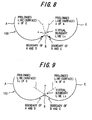
- Figure 8 is an explanatory view, partially similar to Figure 7, but showing the operation of a computer-aided product design system according to the second embodiment of the invention.
- the virtual boundary line Lv is formed with the use of the edge present before the application of fillet
- the virtual boundary line is obtained by prolonging curvature of A and C.
- each of A and C is constituted as a curve (more prcciscly curved surface)
- the curves (curved surfaces) of A and C are prolonged towards the inside of the surfaces (solid model 100). More specifically, after deleting B, the curve (curved surface) constituting A is prolonged toward the inside of the solid model 100 with the same curvature of A to obtain a prolonged line (more precisely a prolonged surface) a , while that constituting C is prolonged in the same direction with the same curvature of C to obtain a prolonged line (more precisely a prolonged surface) c . Then, the virtual boundary line Lv is determined at a point of intersection x of the two prolonged lines a and c .
- B is not a filet, but is a portion of existing surface.
- Figure 9 is an explanatory view, partially similar to Figure 7, but showing the operation of a computer-aided product design system according to a third embodiment of the invention.
- the virtual boundary line is obtained by prolonging tangents of A and C.
- each of A and C is constituted as a curve (more precisely curved surface)
- tangents (more precisely tangential surface) touching the curve (curved surface) constituting A is prolonged toward the inside of the solid model 100 (the inside of the surface) to obtain a prolonged line (more precisely a prolonged surface) 1a
- that touching the curve (curved surface) constituting C is prolonged in the same direction to obtain a prolonged line (more precisely a prolonged surface) 1c .
- the virtual boundary line Lv is determined at the point of intersection x of the two prolonged lines 1a and 1c .
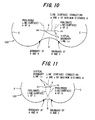
- Figure 10 is an explanatory view, partially similar to Figure 7, but showing the operation of a computer-aided product design system according to a fourth embodiment of the invention.
- the virtual boundary line is obtained by determining positions connecting the prolonging lines from A and C by a minimum distance.
- each of A and C is constituted as a curve (more precisely curved surface)
- the curve (curved surface) constituting A is prolonged toward the inside of the solid model 100 with the same curvature of A to obtain the prolonged line a
- that constituting C is prolonged in the same direction with the same curvature of C to obtain the prolonged line c .
- Figure 11 is an explanatory view, partially similar to Figure 7, but showing the operation of a computer-aided product design system according to a fifth embodiment of the invention.
- the virtual boundary line is obtained by determining the positions connecting the prolonging lines from A and C by a maximum distance.
- each of A and C is constituted as a curve (more precisely curved surface)
- the curve (curved surface) constituting A is prolonged toward the inside of the solid model 100 with the same curvature of A to obtain the prolonged line a
- that constituting C is prolonged in the same direction with the same curvature of C to obtain the prolonged line c .
- positions or locations connecting the prolonged lines a and c by a maximum (in absolute value) distance d is determined and each of the positions xa, xc thus determined is determined to be the virtual boundary line Lv.
- two virtual boundary line are formed in the fifth embodiment.
- the positions defining the distance d becomes maximum in absolute value are each determined to be the virtual boundary line Lv.
- FIG. 12 is an explanatory view, partially similar to Figure 7, but showing the operation of a computer-aided product design system according to a sixth embodiment of the invention.
- the virtual boundary line is obtained by determining a point of contact on a line touching A and C.
- each of A and C is constituted as a curve (more precisely curved surface)
- the curve (curved surface) constituting A is prolonged toward the inside of the solid model 100 with the same curvature of A to obtain the prolonged line a
- that constituting C is prolonged in the same direction with the same curvature of C to obtain the prolonged line c .
- a line (more precisely a surface) 1g is drawn by the designer (engineer) and the positions or locations xa, xc is determined form points of contact of the line with the prolonged lines a and c , and each of the positions xa, xc thus determined is determined to be the virtual boundary line Lv.
- two virtual boundary line are formed in the fifth embodiment.
- the first to sixth embodiments are thus configured to have a system (10) for designing a product (26) having at least a computer (12), a display (14) connected to the computer for displaying result of processing of the computer, an input device (18) connected to the computer for allowing an engineer to enter data and an interactive program (16), stored in the computer, for aiding the engineer to design the product through the display and the input device, the program having a shape modelling function and including at least: product design process for allowing the engineer to design a product model (20) by modelling the product by a geometric model (100) comprising a combination of basic elements through the shape modelling function; and mold design process for allowing the engineer to design a mold (24) for producing the product based on the designed product model (20).
- the characteristic features are that the program (16) of the product design process comprising; virtual boundary line determining means (S10, S12) for determining a virtual boundary line between a portion of surface (A) and rest (C) of the geometric model (100), when a shape of the portion of surface of the geometric model is to be changed; area determining means (S14) for determining an area extending to the virtual boundary line as the portion of surface whose shape is to be changed; and shape changing means (S14) for changing the shape of the portion using a definition of shape of the portion.
- the virtual boundary line determining means determines the virtual boundary line at an edge which was present before the fillet (B) is applied.
- the virtual boundary line determining means prolongs each curve with a same curvature as that of each curve, and determines the virtual boundary line at a point of intersection (x) of the prolonged curves (a, c).
- the virtual boundary line determining means prolongs tangents (1a, 1c) each touching the curves, and determines the virtual boundary line at a point of intersection (x) of the tangents (a, c).
- the virtual boundary line determining means prolongs each curve with a same curvature as that of each curve, determines positions (xa, xc) on the prolonged curves (a, c) such that a distance (d) connecting the positions (xa, xc) is minimum or maximum in absolute value, and determines the virtual boundary line at each of the positions (xa, xc).
- the virtual boundary line determining means prolongs each curve with a same curvature as that of each curve, determines a line (1g) which contacts each curve, and determines the virtual boundary line at each of the points of contact (xa, xc).
- fillet applying means for applying a fillet between the portion of surface (A) and the rest (C) of the geometric model (100), and the fillet applying means applies the fillet using a definition of shape of a portion between the portion of surface (A) and the rest of (C) of the geometric model (100).
- a product design system having a computer and an interactive program stored in the computer for aiding the engineer to design a product and including product design process for allowing the engineer to design a product model and mold design process to design a mold for producing the product based on the designed product model
- the program is rewritten such that a virtual boundary line is determined between a portion of surface (A) and rest (C) of the geometric model (100), when a shape of the portion of surface of the geometric model is to be changed, an area extending to the virtual boundary line is determined as the portion of surface whose shape is to be changed; and the shape of the portion is changed using a definition of shape of the portion.
Landscapes
- Engineering & Computer Science (AREA)
- Physics & Mathematics (AREA)
- Geometry (AREA)
- Computer Graphics (AREA)
- Software Systems (AREA)
- General Physics & Mathematics (AREA)
- Theoretical Computer Science (AREA)
- Architecture (AREA)
- Computer Hardware Design (AREA)
- General Engineering & Computer Science (AREA)
- Moulds For Moulding Plastics Or The Like (AREA)
- Processing Or Creating Images (AREA)
Abstract
Description
Claims (8)
- A system (10) for designing a product (26) having at least a computer (12), a display (14) connected to the computer for displaying result of processing of the computer, an input device (18) connected to the computer for allowing an engineer to enter data and an interactive program (16), stored in the computer, for aiding the engineer to design the product through the display and the input device, the program having a shape modelling function and including at least:CHARACTERIZED IN THAT:product design process for allowing the engineer to design a product model (20) by modelling the product by a geometric model (100) comprising a combination of basic elements through the shape modelling function; andmold design process for allowing the engineer to design a mold (24) for producing the product based on the designed product model (20);the program (16) of the product design process comprising;virtual boundary line determining means (S10, S12) for determining a virtual boundary line between a portion of surface (A) and rest (C) of the geometric model (100), when a shape of the portion of surface of the geometric model is to be changed;area determining means (S14) for determining an area extending to the virtual boundary line as the portion of surface whose shape is to be changed; andshape changing means (S14) for changing the shape of the portion using a definition of shape of the portion .
- A system according to claim 1, wherein, in a case that the portion of surface (A) and the rest (C) of the geometric model (100) are connected by a fillet (B) such that the portion of surface and the rest of the solid model are tangentially continuous with each other, the virtual boundary line determining means determines the virtual boundary line at an edge which was present before the fillet (B) is applied.
- A system according to claim 1, wherein, in a case that the portion of surface (A) and the rest (C) of the geometric model (100) comprises curves, the virtual boundary line determining means prolongs each curve with a same curvature as that of each curve, and determines the virtual boundary line at a point of intersection (x) of the prolonged curves (a, c).
- A system according to claim 1, wherein, in a case that the portion of surface (A) and the rest (C) of the geometric model (100) comprises curves, the virtual boundary line determining means prolongs tangents (1a, 1c) each touching the curves, and determines the virtual boundary line at a point of intersection (x) of the tangents (a, c).
- A system according to claim 1, wherein, in a case that the portion of surface (A) and the rest (C) of the geometric model (100) comprises curves, the virtual boundary line determining means prolongs each curve with a same curvature as that of each curve, determines positions (xa, xc) on the prolonged curves (a, c) such that a distance (d) connecting the positions (xa, xc) is minimum or maximum in absolute value, and determines the virtual boundary line at each of the positions (xa, xc).
- A system according to claim 1, wherein, in a case that the portion of surface (A) and the rest (C) of the geometric model (100) comprises curves, the virtual boundary line determining means prolongs each curve with a same curvature as that of each curve, determines a line (lg) which contacts each curve, and determines the virtual boundary line at each of the points of contact (xa, xc).
- A system according to any of claims 1 to 6, characterized by; fillet applying means (S16) for applying a fillet between the portion of surface (A) and the rest (C) of the geometric model (100).
- A system according to claim 7, wherein the fillet applying means applies the fillet using a definition of shape of a portion between the portion of surface (A) and the rest of (C) of the geometric model (100).
Applications Claiming Priority (2)
| Application Number | Priority Date | Filing Date | Title |
|---|---|---|---|
| JP2001208857A JP4800511B2 (en) | 2001-07-10 | 2001-07-10 | Computer-aided product design equipment |
| JP2001208857 | 2001-07-10 |
Publications (2)
| Publication Number | Publication Date |
|---|---|
| EP1276077A2 true EP1276077A2 (en) | 2003-01-15 |
| EP1276077A3 EP1276077A3 (en) | 2004-11-10 |
Family
ID=19044601
Family Applications (1)
| Application Number | Title | Priority Date | Filing Date |
|---|---|---|---|
| EP02015193A Withdrawn EP1276077A3 (en) | 2001-07-10 | 2002-07-08 | Computer-aided product design system |
Country Status (3)
| Country | Link |
|---|---|
| US (1) | US7068268B2 (en) |
| EP (1) | EP1276077A3 (en) |
| JP (1) | JP4800511B2 (en) |
Cited By (1)
| Publication number | Priority date | Publication date | Assignee | Title |
|---|---|---|---|---|
| WO2010144437A1 (en) * | 2009-06-08 | 2010-12-16 | Parametric Technology Corporation | Correction of topology interference for solid objects in a modeling environment |
Families Citing this family (14)
| Publication number | Priority date | Publication date | Assignee | Title |
|---|---|---|---|---|
| US7630006B2 (en) | 1997-10-09 | 2009-12-08 | Fotonation Ireland Limited | Detecting red eye filter and apparatus using meta-data |
| FR2857889B1 (en) * | 2003-07-23 | 2005-09-23 | Snecma Moteurs | PROCESS FOR PRODUCING PARTS BY PRECISION FORGING |
| US7545373B2 (en) | 2004-08-03 | 2009-06-09 | Nextpat Limited | Applications with integrated capture |
| US20090109130A1 (en) * | 2007-10-31 | 2009-04-30 | Murphy Terence J | Methods and apparatus for interactive movable computer mediated information display |
| WO2010050010A1 (en) * | 2008-10-29 | 2010-05-06 | 富士通株式会社 | Design support program, design support method, and design support device |
| US8462154B2 (en) * | 2009-03-12 | 2013-06-11 | Siemens Product Lifecycle Management Software Inc. | System and method for determining a virtual curve in an object model |
| JP2010262528A (en) * | 2009-05-08 | 2010-11-18 | Mitsubishi Electric Corp | Automatic programming device and its operation program |
| CN103150447B (en) * | 2013-03-22 | 2016-03-23 | 杭州电子科技大学 | A kind of engineering goods Fast design method based on virtual instrument and reverse-engineering |
| US9690878B2 (en) * | 2013-05-28 | 2017-06-27 | Siemens Prodcut Lifecycle Management Software Inc | Geometric modeling with mutually dependent blends |
| CN103646142A (en) * | 2013-12-14 | 2014-03-19 | 西安工业大学 | Method for creating virtual prototype product of CMM (coordinate measuring machine) |
| EP3502930B1 (en) * | 2017-12-22 | 2025-04-30 | Dassault Systèmes | Method for computing and manufacturing an unfolded part of a modeled bended part of a 3d object |
| CN110992483B (en) * | 2019-11-19 | 2024-04-09 | 中国石油大学(华东) | Method for printing real three-dimensional fracture-vuggy reservoir physical model based on reverse modeling |
| JP7485435B2 (en) * | 2020-11-20 | 2024-05-16 | イマゴワークス インコーポレイテッド | Method for generating 3D model for digital dentistry through multiset operation based on virtual bridge |
| US12599953B2 (en) * | 2022-02-28 | 2026-04-14 | Spirit Aerosystems, Inc. | Method for forming and heat treating near net shape complex structures from sheet metal |
Family Cites Families (13)
| Publication number | Priority date | Publication date | Assignee | Title |
|---|---|---|---|---|
| JPH01255069A (en) * | 1988-04-04 | 1989-10-11 | Ricoh Co Ltd | Mechanical drawing recognition method |
| JP2905225B2 (en) * | 1989-08-22 | 1999-06-14 | 株式会社リコー | Three-dimensional shape design history management method |
| JPH0457167A (en) * | 1990-06-27 | 1992-02-24 | Sharp Corp | Parametric design device |
| JP3276516B2 (en) * | 1994-09-13 | 2002-04-22 | 株式会社リコー | 3D shape generator |
| JP3195498B2 (en) * | 1994-09-13 | 2001-08-06 | キャダムシステム株式会社 | Method and apparatus for creating three-dimensional shape |
| US6120171A (en) * | 1996-06-14 | 2000-09-19 | Mohammad Salim Shaikh | Fully integrated machinable profile based parametric solid modeler |
| US6862023B1 (en) * | 1995-08-18 | 2005-03-01 | Mohammad Salim Shaikh | Fully integrated machinable profile based parametric solid modeler |
| TW311113B (en) * | 1995-11-02 | 1997-07-21 | Fujitsu Ltd | |
| JPH09319772A (en) * | 1996-05-30 | 1997-12-12 | Toyota Motor Corp | Product design system |
| JP3852135B2 (en) * | 1996-09-04 | 2006-11-29 | 日産自動車株式会社 | Phase element identification device for shape modeler and instruction re-execution device using the same |
| JPH10124545A (en) * | 1996-10-17 | 1998-05-15 | Meidensha Corp | Fillet editing method for graphic |
| JP3306359B2 (en) * | 1997-08-29 | 2002-07-24 | 三洋電機株式会社 | Mold design method by three-dimensional CAD and its design device |
| JP3657771B2 (en) * | 1998-04-22 | 2005-06-08 | 富士通株式会社 | 3D model creation device |
-
2001
- 2001-07-10 JP JP2001208857A patent/JP4800511B2/en not_active Expired - Fee Related
-
2002
- 2002-07-08 EP EP02015193A patent/EP1276077A3/en not_active Withdrawn
- 2002-07-09 US US10/190,479 patent/US7068268B2/en not_active Expired - Fee Related
Cited By (2)
| Publication number | Priority date | Publication date | Assignee | Title |
|---|---|---|---|---|
| WO2010144437A1 (en) * | 2009-06-08 | 2010-12-16 | Parametric Technology Corporation | Correction of topology interference for solid objects in a modeling environment |
| US9223904B2 (en) | 2009-06-08 | 2015-12-29 | Ptc Inc. | Correction of topology interference for solid objects in a modeling environment |
Also Published As
| Publication number | Publication date |
|---|---|
| US7068268B2 (en) | 2006-06-27 |
| US20030014228A1 (en) | 2003-01-16 |
| EP1276077A3 (en) | 2004-11-10 |
| JP2003022285A (en) | 2003-01-24 |
| JP4800511B2 (en) | 2011-10-26 |
Similar Documents
| Publication | Publication Date | Title |
|---|---|---|
| US7068268B2 (en) | Computer-aided product design system | |
| EP1302904B1 (en) | Object modeling | |
| JP4857012B2 (en) | Method for computer-aided design (CAD) of modeled objects having several faces | |
| US5619625A (en) | Method for interpolating smooth free-form surfaces into curve mesh including composite curves | |
| CN106959669B (en) | Notch detection | |
| EP2257899A1 (en) | Reducing the size of a model using visibility factors | |
| US7069094B2 (en) | Computer-aided product design system | |
| JP3019398B2 (en) | Free-form surface machining data creation method | |
| Kuragano | FRESDAM system for design of aesthetically pleasing free-form objects and generation of collision-free tool paths | |
| JPH10255079A (en) | How to create mesh data on a curved surface | |
| WO2006097926A2 (en) | Methods and systems for creating and altering cad models | |
| JP2002373187A (en) | Computer aided product design equipment | |
| JP3727608B2 (en) | Method and system for industrializing parts | |
| JP3019383B2 (en) | Roughing data creation method | |
| JP4670600B2 (en) | Design support method | |
| JP3019387B2 (en) | Roughing data creation method | |
| JP4783145B2 (en) | How to create a 3D tire model | |
| JP3792617B2 (en) | Injection mold design method | |
| JP2000225434A (en) | Method of creating intermediate material shape of forged part and method of designing forging die | |
| JP2696914B2 (en) | Mold making method | |
| JP3251877B2 (en) | Three-dimensional grid generation method and system | |
| JP2000185326A (en) | Mold cavity shape creation method | |
| JP2830026B2 (en) | Free-form surface machining data creation method | |
| JPH09231410A (en) | 3D CAD equipment | |
| JPH05282025A (en) | Shape data creation method |
Legal Events
| Date | Code | Title | Description |
|---|---|---|---|
| PUAI | Public reference made under article 153(3) epc to a published international application that has entered the european phase |
Free format text: ORIGINAL CODE: 0009012 |
|
| 17P | Request for examination filed |
Effective date: 20020708 |
|
| AK | Designated contracting states |
Kind code of ref document: A2 Designated state(s): AT BE BG CH CY CZ DE DK EE ES FI FR GB GR IE IT LI LU MC NL PT SE SK TR |
|
| AX | Request for extension of the european patent |
Free format text: AL;LT;LV;MK;RO;SI |
|
| PUAL | Search report despatched |
Free format text: ORIGINAL CODE: 0009013 |
|
| RIC1 | Information provided on ipc code assigned before grant |
Ipc: 7G 06T 17/40 A |
|
| AK | Designated contracting states |
Kind code of ref document: A3 Designated state(s): AT BE BG CH CY CZ DE DK EE ES FI FR GB GR IE IT LI LU MC NL PT SE SK TR |
|
| AX | Request for extension of the european patent |
Extension state: AL LT LV MK RO SI |
|
| AKX | Designation fees paid |
Designated state(s): DE FR GB |
|
| 17Q | First examination report despatched |
Effective date: 20070921 |
|
| STAA | Information on the status of an ep patent application or granted ep patent |
Free format text: STATUS: THE APPLICATION IS DEEMED TO BE WITHDRAWN |
|
| 18D | Application deemed to be withdrawn |
Effective date: 20140202 |
|
| REG | Reference to a national code |
Ref country code: DE Ref legal event code: R079 Free format text: PREVIOUS MAIN CLASS: G06T0017400000 Ipc: G06T0019000000 |
|
| REG | Reference to a national code |
Ref country code: DE Ref legal event code: R079 Free format text: PREVIOUS MAIN CLASS: G06T0017400000 Ipc: G06T0019000000 Effective date: 20141106 |