EP1275991A2 - Optical fiber and optical signal transmission system using this optical fiber - Google Patents

Optical fiber and optical signal transmission system using this optical fiber Download PDF

Info

Publication number
EP1275991A2
EP1275991A2 EP02254772A EP02254772A EP1275991A2 EP 1275991 A2 EP1275991 A2 EP 1275991A2 EP 02254772 A EP02254772 A EP 02254772A EP 02254772 A EP02254772 A EP 02254772A EP 1275991 A2 EP1275991 A2 EP 1275991A2
Authority
EP
European Patent Office
Prior art keywords
optical fiber
refractive index
optical signal
optical
signal transmission
Prior art date
Legal status (The legal status is an assumption and is not a legal conclusion. Google has not performed a legal analysis and makes no representation as to the accuracy of the status listed.)
Withdrawn
Application number
EP02254772A
Other languages
German (de)
French (fr)
Other versions
EP1275991A3 (en
Inventor
Tamotsu The Furukawa Electric Co. Ltd Kamiya
Current Assignee (The listed assignees may be inaccurate. Google has not performed a legal analysis and makes no representation or warranty as to the accuracy of the list.)
Furukawa Electric Co Ltd
Original Assignee
Furukawa Electric Co Ltd
Priority date (The priority date is an assumption and is not a legal conclusion. Google has not performed a legal analysis and makes no representation as to the accuracy of the date listed.)
Filing date
Publication date
Application filed by Furukawa Electric Co Ltd filed Critical Furukawa Electric Co Ltd
Publication of EP1275991A2 publication Critical patent/EP1275991A2/en
Publication of EP1275991A3 publication Critical patent/EP1275991A3/en
Withdrawn legal-status Critical Current

Links

Images

Classifications

    • GPHYSICS
    • G02OPTICS
    • G02BOPTICAL ELEMENTS, SYSTEMS OR APPARATUS
    • G02B6/00Light guides; Structural details of arrangements comprising light guides and other optical elements, e.g. couplings
    • G02B6/02Optical fibres with cladding with or without a coating
    • G02B6/036Optical fibres with cladding with or without a coating core or cladding comprising multiple layers
    • G02B6/03616Optical fibres characterised both by the number of different refractive index layers around the central core segment, i.e. around the innermost high index core layer, and their relative refractive index difference
    • G02B6/03638Optical fibres characterised both by the number of different refractive index layers around the central core segment, i.e. around the innermost high index core layer, and their relative refractive index difference having 3 layers only
    • G02B6/03644Optical fibres characterised both by the number of different refractive index layers around the central core segment, i.e. around the innermost high index core layer, and their relative refractive index difference having 3 layers only arranged - + -
    • GPHYSICS
    • G02OPTICS
    • G02BOPTICAL ELEMENTS, SYSTEMS OR APPARATUS
    • G02B6/00Light guides; Structural details of arrangements comprising light guides and other optical elements, e.g. couplings
    • G02B6/02Optical fibres with cladding with or without a coating
    • G02B6/02004Optical fibres with cladding with or without a coating characterised by the core effective area or mode field radius
    • G02B6/02028Small effective area or mode field radius, e.g. for allowing nonlinear effects
    • GPHYSICS
    • G02OPTICS
    • G02BOPTICAL ELEMENTS, SYSTEMS OR APPARATUS
    • G02B6/00Light guides; Structural details of arrangements comprising light guides and other optical elements, e.g. couplings
    • G02B6/02Optical fibres with cladding with or without a coating
    • G02B6/036Optical fibres with cladding with or without a coating core or cladding comprising multiple layers
    • G02B6/03616Optical fibres characterised both by the number of different refractive index layers around the central core segment, i.e. around the innermost high index core layer, and their relative refractive index difference
    • G02B6/03622Optical fibres characterised both by the number of different refractive index layers around the central core segment, i.e. around the innermost high index core layer, and their relative refractive index difference having 2 layers only
    • G02B6/03627Optical fibres characterised both by the number of different refractive index layers around the central core segment, i.e. around the innermost high index core layer, and their relative refractive index difference having 2 layers only arranged - +
    • HELECTRICITY
    • H04ELECTRIC COMMUNICATION TECHNIQUE
    • H04BTRANSMISSION
    • H04B10/00Transmission systems employing electromagnetic waves other than radio-waves, e.g. infrared, visible or ultraviolet light, or employing corpuscular radiation, e.g. quantum communication
    • H04B10/29Repeaters
    • H04B10/291Repeaters in which processing or amplification is carried out without conversion of the main signal from optical form
    • H04B10/2912Repeaters in which processing or amplification is carried out without conversion of the main signal from optical form characterised by the medium used for amplification or processing
    • H04B10/2916Repeaters in which processing or amplification is carried out without conversion of the main signal from optical form characterised by the medium used for amplification or processing using Raman or Brillouin amplifiers
    • GPHYSICS
    • G02OPTICS
    • G02BOPTICAL ELEMENTS, SYSTEMS OR APPARATUS
    • G02B6/00Light guides; Structural details of arrangements comprising light guides and other optical elements, e.g. couplings
    • G02B6/02Optical fibres with cladding with or without a coating
    • G02B6/02214Optical fibres with cladding with or without a coating tailored to obtain the desired dispersion, e.g. dispersion shifted, dispersion flattened
    • G02B6/02219Characterised by the wavelength dispersion properties in the silica low loss window around 1550 nm, i.e. S, C, L and U bands from 1460-1675 nm
    • G02B6/02252Negative dispersion fibres at 1550 nm
    • G02B6/02261Dispersion compensating fibres, i.e. for compensating positive dispersion of other fibres
    • HELECTRICITY
    • H01ELECTRIC ELEMENTS
    • H01SDEVICES USING THE PROCESS OF LIGHT AMPLIFICATION BY STIMULATED EMISSION OF RADIATION [LASER] TO AMPLIFY OR GENERATE LIGHT; DEVICES USING STIMULATED EMISSION OF ELECTROMAGNETIC RADIATION IN WAVE RANGES OTHER THAN OPTICAL
    • H01S3/00Lasers, i.e. devices using stimulated emission of electromagnetic radiation in the infrared, visible or ultraviolet wave range
    • H01S3/05Construction or shape of optical resonators; Accommodation of active medium therein; Shape of active medium
    • H01S3/06Construction or shape of active medium
    • H01S3/063Waveguide lasers, i.e. whereby the dimensions of the waveguide are of the order of the light wavelength
    • H01S3/067Fibre lasers
    • H01S3/06708Constructional details of the fibre, e.g. compositions, cross-section, shape or tapering
    • H01S3/06729Peculiar transverse fibre profile
    • HELECTRICITY
    • H01ELECTRIC ELEMENTS
    • H01SDEVICES USING THE PROCESS OF LIGHT AMPLIFICATION BY STIMULATED EMISSION OF RADIATION [LASER] TO AMPLIFY OR GENERATE LIGHT; DEVICES USING STIMULATED EMISSION OF ELECTROMAGNETIC RADIATION IN WAVE RANGES OTHER THAN OPTICAL
    • H01S3/00Lasers, i.e. devices using stimulated emission of electromagnetic radiation in the infrared, visible or ultraviolet wave range
    • H01S3/30Lasers, i.e. devices using stimulated emission of electromagnetic radiation in the infrared, visible or ultraviolet wave range using scattering effects, e.g. stimulated Brillouin or Raman effects
    • H01S3/302Lasers, i.e. devices using stimulated emission of electromagnetic radiation in the infrared, visible or ultraviolet wave range using scattering effects, e.g. stimulated Brillouin or Raman effects in an optical fibre

Definitions

  • the present invention relates to an optical fiber, more particularly relates to an optical fiber suitably used for wavelength division multiplexing (WDM) transmission and an optical signal transmission system (optical signal transmission line) using that optical fiber.
  • WDM wavelength division multiplexing
  • Raman amplification will be explained here.
  • the molecular vibration or lattice vibration of that substance causes the generation of light of a somewhat longer wavelength than the original wavelength. This light is called Raman scattering light.
  • the stimulated light introduced is made more intensive, further, intensive phase-aligned Raman scattering light may be produced. This is called “induced Raman scattering light”.
  • the introduced signal light and the induced Raman scattering light match in wavelength, the induced Raman scattering light is changed to the same degree as the signal light and the signal light is amplified.
  • “Raman amplification” is a technique for amplification of an optical signal using the fact that light scattered by atoms making up the material, that is, a silica-based glass (induced Raman scattering light), is converted to a wavelength different from that at the time of incidence and scattered when intensive stimulated light is introduced fired into an optical fiber.
  • Raman amplifier uses the amplification action arising due to a non-linear optical phenomenon occurring in an optical fiber in this way.
  • Raman amplification the phenomenon is known where the maximum value of a Raman gain is obtained at a wavelength away from a stimulated light source wavelength by about 100 nm to a longer wavelength side. Using this phenomenon, it has been attempted to amplify a WDM optical signal using a plurality of stimulated light sources of different wavelengths (hereinafter referred to as a "wavelength multiplexed stimulated light source").
  • a wavelength band of the wavelength multiplexed stimulated light source has to be no more than about 100 nm so that the stimulated light at a longest wavelength of the wavelength multiplexed stimulated light source does not overlap the signal light at a shortest wavelength of the WDM signal.
  • SMF Since SMF has a relatively large effective area (Aeff) of about 80 ⁇ m 2 , SMF is poor in efficiency for Raman amplification. When using SMF, an optical power of at least 1W is required in total for the wavelength multiplexed stimulated light source. This is not economical.
  • an optical fiber increasing in dopant so as to raise a refractive index of a core has inherently large Rayleigh scattering.
  • the Rayleigh scattering coefficient is known as an indicator expressing the magnitude of the Rayleigh scattering.
  • the value of the Rayleigh scattering coefficient is about 0.9 ⁇ m 4 ⁇ dB/km with the above-mentioned SMF, while is almost always more than 1.1 ⁇ m 4 ⁇ dB/km with an optical fiber increasing in dopant to raise the refractive index of the core.
  • an optical fiber increasing in dopant to raise a refractive index of a core has a zero dispersion wavelength in the signal light band or stimulated light band, so was susceptible to the disadvantages of four wave mixing (FWM) etc.
  • optical fibers suffered from the disadvantages that they were not suitable as optical fibers for Raman amplification.
  • An object of the present invention is to provide an optical fiber having a small Rayleigh scattering coefficient and a high Raman efficiency.
  • Another object of the present invention is to provide an optical fiber not having a zero dispersion wavelength in a signal light wavelength band and stimulated light wavelength band.
  • Still another object of the present invention is to provide an optical signal transmission system (optical signal transmission line) performing Raman amplification by using such an optical fiber.
  • an optical fiber having a refractive index profile, including at least one annular region between a center core and a cladding layer, having a Rayleigh scattering coefficient not more than 1 ⁇ m 4 ⁇ dB/km, a first relative refractive index difference of the center core with respect to the cladding layer of a positive value of not more than 0.9%, a second relative refractive index difference of an annular region adjoining the center core with respect to the cladding layer from -0.7% to -0.2%, and an effective area (Aeff) not more than 60 ⁇ m 2 .
  • an optical signal transmission system having an optical signal transmission apparatus for transmitting an optical signal, a Raman amplification means for amplifying signal light transmitted from the optical signal transmission apparatus, and an optical signal reception apparatus for receiving a signal transmitted from the Raman amplification means
  • the Raman amplification means having an optical signal transmission line including in at least part an optical fiber having a refractive index profile including at least one annular region between a center core and a cladding layer and having a Rayleigh scattering coefficient not more than 1 ⁇ m 4 ⁇ dB/km, a first relative refractive index difference ⁇ 1 of the center core with respect to the cladding layer of a positive value of not more than 0.9%, a second relative refractive index difference ⁇ 2 of an annular region adjoining the center core with respect to the cladding layer from -0.7% to -0.2%, and an effective area (Aeff) not more than 60 ⁇ m 2 and receiving signal light emitted from the optical signal transmission apparatus
  • the Rayleigh scattering coefficient is a parameter which fluctuates affected by various factors such as the refractive index profile, glass composition, and manufacturing conditions. It cannot be defined even if just for example taking up the shape of the refractive index profile. From the viewpoint that it is good to measure the Rayleigh scattering coefficient of an optical fiber directly when trying to consider a Rayleigh scattering coefficient for judgement of the suitability of an optical fiber used for a Raman amplification system for the system, the inventors considered the Rayleigh scattering coefficient of optical fibers used for Raman amplification systems and discovered and defined suitable values for the same as illustrated in Table 1 and Table 2.
  • the required characteristics of the optical fiber are dependent on the configuration of the transmission line. Therefore, the shape of the refractive index profile is selected to satisfy the required transmission characteristics of the optical fiber.
  • the optical fiber illustrated in FIGS. 1A and 1B and the optical fiber illustrated in FIGS. 2A and 2B, which are explained below as embodiments according to the present invention, are satisfied each different required characteristics. The difference in the effects and actions result in differences in the required characteristics of the optical fiber. To realize these, it is possible to suitably select the optical fibers of the configurations illustrated in FIGS. 1A and 1B and FIGS. 2A and 2B explained below.
  • FIG. 1A is a sectional view of a first embodiment of an optical fiber according to the present invention
  • FIG. 1B is a graph illustrating the refractive index profile of the optical fiber illustrated in FIG. 1A.
  • the optical fiber 1 of the first embodiment illustrated in FIG. 1A and FIG. 1B has a center core 11, an annular region 12 formed adjoining the peripheral of the center core 11, and a cladding layer 13 formed on the peripheral of the annular region 12.
  • the refractive index of the center core 11 is designated here as n11, the refractive index of the annular region 12 as n12, and the refractive index of the cladding layer as n13.
  • the relative refractive index difference between the cladding layer 13 and the center core is designated as ⁇ 1, while the relative refractive index difference between the cladding layer 13 and the annular region 12 is designated as ⁇ 2.
  • the refractive index n12 of the annular region 12 is smaller than the refractive index n13 of the cladding layer 13.
  • the refractive index n11 of the center core 11 is higher than the refractive index n13 of the cladding layer 13. Therefore, in the example illustrated in FIG. 1B, ⁇ 1>0, ⁇ 2 ⁇ 0.
  • the optical fiber illustrated in FIG. 1A and FIG. 1B is formed to have a Rayleigh scattering coefficient of not more than 1 ⁇ m 4 ⁇ dB/km, a first relative refractive index difference ⁇ 1 of a positive value of not more than 0.9%, a second relative refractive index difference ⁇ 2 of -0.7% to -0.2%, and an effective area (Aeff) of not more than 60 ⁇ m 2 .
  • the reason why the Rayleigh scattering coefficient is made not more than 1 ⁇ m 4 ⁇ dB/km is that when the Rayleigh scattering coefficient is larger than this value, deterioration of the SNR due to double Rayleigh scattering can no longer be ignored.
  • the reason why the first relative refractive index difference ⁇ 1 is made a positive value of not more than 0.9% is that if the first relative refractive index difference ⁇ 1 is made larger than 0.9%, it is more possible for the Rayleigh scattering coefficient to become greater than 1 ⁇ m 4 ⁇ dB/km and deterioration of the SNR can no longer be ignored.
  • the reason why the second relative refractive index difference ⁇ 2 is made from -0.7% to -0.2% is that if the second relative refractive index difference ⁇ 2 is outside of this range, it is not possible for the optical fiber becoming very suitable to WDM transmission even if the first relative refractive index difference ⁇ 1 is made a positive value of not more than 0.9%.
  • the reason why the effective area (Aeff) is made not more than 60 ⁇ m 2 is that a drop in the efficiency of Raman amplification is induced when the effective area (Aeff) is larger than 60 ⁇ m 2 .
  • the zero dispersion wavelength is preferably outside the range of 1400 nm to 1600 nm.
  • the reason why the zero dispersion wavelength is made outside of the range of 1400 nm to 1600 nm is that when performing WDM transmission around the wavelength of 1500 to 1600 nm using Raman amplification, if the zero dispersion wavelength is in the range of 1400 nm to 1600 nm, it is more possible for FWM to occur in the wavelength band of the stimulated light or signal light.
  • FIG. 2A is a sectional view of a second embodiment of the optical fiber of the present invention
  • FIG. 2B is a graph illustrating the profile of the refractive index of the optical fiber illustrated in FIG. 2A.
  • the optical fiber 2 of the second embodiment illustrated in FIG. 2A and FIG. 2B has a first annular region 22 formed on the peripheral of the center core 21, a second annular region 23 formed on the peripheral of the first annular region 22, and a cladding layer 24 formed on the peripheral of the second annular region 23.
  • the optical fiber 2 illustrated in FIG. 2A and FIG. 2B has the additional second annular region 23.
  • the refractive index of the center core 21 is designated as n21, the refractive index of the first annular region 22 as n22, the refractive index of the second annular region 23 as n23, and the refractive index of the cladding layer 24 as n24.
  • the first relative refractive index difference between the cladding layer 24 and the center core 21 is designated as ⁇ 1a
  • the second relative refractive index difference between the cladding layer 24 and the first annular region 22 as ⁇ 2a
  • the relative refractive index difference between the cladding layer 24 and the second annular region 23 as ⁇ 3a.
  • the refractive index n22 of the first annular region 22 is smaller than the refractive index n24 of the cladding layer 24.
  • the refractive index n21 of the center core 21 is higher than the refractive index n24 of the cladding layer 24.
  • the refractive index n23 of the second annular region 23 is higher than the refractive index n24 of the cladding layer 24 and lower than the refractive index n21 of the center core 21. Therefore, in the example illustrated in FIG. 2B, ⁇ 1a>0, ⁇ 2a ⁇ 0, and ⁇ 3a>0.
  • the optical fiber illustrated in FIG. 2A and FIG. 2B is formed to have a Rayleigh scattering coefficient of not more than 1 ⁇ m 4 ⁇ dB/km, a first relative refractive index difference ⁇ 1a of a positive value of not more than 0.9%, a second relative refractive index difference ⁇ 2a of -0.7% to -0.2%, and an effective area (Aeff) of not more than 60 ⁇ m 2 .
  • the zero dispersion wavelength is preferably outside the range of 1400 nm to 1600 nm.
  • the reason why the zero dispersion wavelength is made outside of the range of 1400 nm to 1600 nm is the same as the reason explained for the optical fiber illustrated in FIG. 1A and FIG. 1B.
  • first relative refractive index difference ⁇ 1a For the optical fiber illustrated in FIG. 2A and FIG. 2B as well, only the upper limits of the Rayleigh scattering coefficient, first relative refractive index difference ⁇ 1a, and effective area (Aeff) are defined, but if either the Rayleigh scattering coefficient or first relative refractive index difference ⁇ 1a increases, the other also increases. Further, if either the Rayleigh scattering coefficient or the effective area (Aeff) increases, the other decreases. Therefore, by defining the upper limits of the Rayleigh scattering coefficient, first relative refractive index difference ⁇ 1a, and effective area (Aeff), the lower limits are substantially also defined.
  • the required characteristics of the optical fiber is dependent on the configuration of the optical signal transmission line. Therefore, the refractive index profile is selected to satisfy the transmission characteristics required for each optical fiber.
  • the optical fiber illustrated in FIGS. 1A and 1B and the optical fiber illustrated in FIGS. 2A and 2B are satisfied each required characteristics.
  • the differences in the effects and actions result in differences in the required characteristics of the optical fibers. To realize this, it is possible to suitably select optical fibers of the configurations shown in FIGS. 1A and 1B and FIGS. 2A and 2B.
  • optical fiber according to the present invention is not limited to the optical fibers illustrated in FIGS. 1A and 1B and FIGS. 2A and 2B.
  • this optical fiber preferably has a zero dispersion wavelength outside of the range of 1400 nm to 1600 nm.
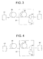
  • FIG. 3 is a view of an embodiment of an optical signal transmission system using an optical fiber according to the present invention.
  • the optical signal transmission system 3 using the optical fiber of the first embodiment has an optical signal transmission apparatus 31, an optical signal reception apparatus 32, a wavelength multiplex stimulated light source 33, an optical coupling means 34, a first optical signal transmission line 35, and a second optical signal transmission line 36.
  • the optical fiber explained with reference to FIGS. 1A and 1B or FIGS. 2A and 2B is used.
  • optical fiber of an embodiment according to the present invention for at least part of the second optical signal transmission line 36.
  • the optical signal transmission apparatus 31 includes a light emitting element for transmitting an optical signal corresponding to the transmitted signal, for example, a semiconductor laser, and a transmission signal processing circuit.
  • the transmission signal processing circuit stimulates the semiconductor laser in accordance with the transmitted signal and emits signal light from the semiconductor laser to the second optical signal transmission line 36.
  • the optical signal reception apparatus 32 includes a light receiving element, for example, a photodiode, and an optical signal processing circuit. It receives an optical signal transmitted from a Raman amplifier 37 by a photodiode, converts it to an electrical signal, and has the signal processing circuit perform desired signal processing on the signal converted to an electrical signal.
  • a light receiving element for example, a photodiode
  • an optical signal processing circuit receives an optical signal transmitted from a Raman amplifier 37 by a photodiode, converts it to an electrical signal, and has the signal processing circuit perform desired signal processing on the signal converted to an electrical signal.
  • the wavelength multiplexed stimulated light source 33, the optical coupling means 34, and the optical signal transmission line 35 form a Raman amplifier (region surrounded by broken line).
  • This type of Raman amplifier 37 is called a distributed Raman amplifier.
  • the wavelength multiplexed stimulated light source 33 is comprised of a plurality of stimulated light sources different in wavelength and provides a plurality of stimulated light of different wavelengths.
  • the optical coupling means 34 is comprised of for example a dichroic mirror, WDM coupler, or other WDM filter etc. and has the function of sending the plurality of stimulated light different in wavelength from the wavelength multiplexed stimulated light source 33 to the optical signal transmission line 35. Due to this, Raman amplification is performed inside the optical signal transmission line 35 having the optical fiber explained with reference to FIGS. 1A and 1B or FIGS. 2A and 2B at least at part thereof.
  • the optical signal transmission line 35 in FIG. 3 is directly related to the action of Raman amplification.
  • the optical fiber used for the optical signal transmission line is required to have a small Rayleigh scattering coefficient and a high Raman efficiency. Further, from the viewpoint of suppressing the occurrence of FWM, the optical fiber used for the optical signal transmission line 35 is required to have a zero dispersion wavelength not in the signal light wavelength band or stimulated light wavelength band.
  • the optical fiber illustrated in FIG. 1A and FIG. 1B is used for part of the first optical signal transmission line 35, since the Rayleigh scattering coefficient is not more than 1 ⁇ m 4 ⁇ dB/km, the first relative refractive index difference ⁇ 1 is a positive value of not more than 0.9%, the second relative refractive index difference ⁇ 2 is from -0.7% to -0.2%, and the effective area (Aeff)is not more than 60 ⁇ m 2 , the Raman efficiency is high. Further, since the zero dispersion wavelength is outside of the range of 1400 nm to 1600 nm, the occurrence of FWM is suppressed.
  • optical fiber of the embodiment according to the present invention illustrated in FIG. 1A and FIG. 1B or FIG. 2A and FIG. 2B has the above characteristics and can satisfy these requirements.
  • optical signal transmission line 35 and the optical signal transmission line 36 are convenient for distinction of the portion where Raman amplification is performed and where it is not.
  • the present invention naturally includes embodiments where the optical signal transmission line 35 and the optical signal transmission line 36 are configured by one type of optical fibers.
  • FIG. 4 is a view of another embodiment of an optical signal transmission system using an optical fiber according to the present invention.
  • the optical signal transmission system 4 using an optical fiber of the second embodiment has an optical signal transmission apparatus 41, an optical signal reception apparatus 42, a wavelength multiplexed stimulated light source 43, an optical coupling means 44, an optical signal amplification fiber 45, and an optical fiber 46.
  • optical fiber explained with reference to FIG. 1A and FIG. 1B or FIG. 2A and FIG. 2B is used for at least part of the optical signal amplification fiber 45.
  • optical fiber explained with reference to FIG. 1A and FIG. 1B or FIG. 2A and FIG. 2B is used for at least part of the optical fiber 46.
  • the wavelength multiplexed stimulated light source 43, optical coupling means 44, and optical signal amplification fiber 45 form a Raman amplifier 47 (area surrounded by solid line). This type of Raman amplifier 47 is called a discrete Raman amplifier.
  • the wavelength multiplexed stimulated light source 43 and optical coupling means 44 are similar to the wavelength multiplexed stimulated light source 33 and optical coupling means 34 explained with reference to FIG. 3.
  • Raman amplification is performed inside the optical amplification fiber 45.
  • the optical signal transmission line 45 is directly related to Raman amplification.
  • the optical fiber used for the optical signal amplification fiber 45 is required to have a small Rayleigh scattering coefficient and a high Raman efficiency. Further, from the viewpoint of suppressing the occurrence of FWM, the optical fiber used for the optical signal amplification fiber 45 is required to have a zero dispersion wavelength not in the signal light wavelength band or stimulated light wavelength band.
  • optical fiber according to the present invention can satisfy these requirements.
  • Raman amplifier 37 called a distributed Raman amplifier comprised of the wavelength multiplexed stimulated light source 33, optical coupling means 34, and optical signal transmission line 35 illustrated in FIG. 3
  • Raman amplifier 47 called a discrete Raman amplifier comprised of the wavelength multiplexed stimulated light source 43, optical coupling means 44, and optical signal amplification fiber 45 illustrated in FIG. 4
  • Raman amplification is amplification occurring in a transmission line (transmission fiber) as explained above, so can be called a system for introducing amplified light other than transmission light into the transmission line.
  • the case of use of a fiber in a cable as the transmission line is referred to as the "distributed type" illustrated in FIG. 3, while the case of introducing amplified light into a fiber built into equipment like a dispersion-compensating module (in state wrapped into a coil and installed in a relay station etc.) is referred to as a "discrete type".
  • optical signal transmission line 35 of FIG. 3 The difference between the optical signal transmission line 35 of FIG. 3 and the optical signal amplification fiber 45 of FIG. 4 is the difference in the mode of use explained above (whether used as cable or other transmission line or used in a manner built into equipment such as a dispersion-compensating module).
  • optical fibers used along with the transmission lines and dispersion-compensating modules depending on the configuration and application of the transmission lines and transmission systems.
  • the ones relating to the present invention are required to have the refractive index profile of FIGS. 1A and 1B or FIGS. 2A and 2B.
  • the definitions of the refractive index difference and other minor parameters is dependent on the type or application, however, so in the present invention, the content described in the specification is covered.
  • the Raman amplifier 37 of FIG. 3 shows a conceptual range including even transmission lines where Raman amplification occurs and is illustrated with the fiber 35 and fiber 36 as separate though the same.
  • the Raman amplifier 47 of FIG. 4 is illustrated with the fiber in the dispersion-compensating module as the optical amplification fiber 45.
  • Optical fibers of the first and second embodiments according to the present invention and optical fibers of comparative examples are shown in Table 1.
  • Ex. 1 Ex. 2 Ex. 3 Comp. Ex. 1 Comp. Ex. 2 Comp. Ex. 3 ⁇ 1 0.50 0.62 0.85 0.30 1.10 2.00 ⁇ 2 -0.25 -0.41 -0.43 None -0.15 -0.52 ⁇ 3 0.22 None None None None 0.30 None Cladding internal diameter 22.2 14.8 13.1 10.0 15.0 3.8 Dispersion 11.6 10.6 7.2 16.9 4.0 -75 Rayleigh scattering coefficient 0.89 0.94 0.97 0.90 1.10 2.20 Aeff 57 30 30 79 72 18
  • Example 1 is an example of an optical fiber of the configuration illustrated in FIG. 2A and FIG. 2B exhibiting values of relative refractive index differences ⁇ 1a, ⁇ 2a, and ⁇ 3a
  • Examples 2 and 3 are examples of optical fibers of the configuration illustrated in FIG. 1A and 1B exhibiting values of the relative refractive index differences ⁇ 1 and ⁇ 2, but not a value of the relative refractive index difference ⁇ 3a.
  • Comparative Example 1 is an example of a single mode fiber (SMF) since only the relative refractive index difference ⁇ 1 is exhibited.
  • SMF single mode fiber
  • Comparative Example 2 is an example of an optical fiber of the configuration illustrated in FIG. 2A and FIG. 2B since ⁇ 1, ⁇ 2, and ⁇ 3 are exhibited. It is an example of an optical fiber having a high relative refractive index difference ⁇ 1 of 1.10, a large value of the Rayleigh scattering coefficient of at least 1.1, and increasing in much more dopant for raising the higher refractive index of the core.
  • the optical fiber of Comparative Example 2 is used for the optical signal transmission line as an optical fiber enlarged in effective area (Aeff).
  • Comparative Example 3 is an example of an optical fiber of the configuration illustrated in FIG. 1A and FIG. 1B since ⁇ 1 and ⁇ 2 are exhibited. However, it is an example of a dispersion-compensating fiber (DCF) reduced in dispersion to -75 ps/nm/km and an example having a high relative refractive index difference ⁇ 1 of 1.10, a large value of the Rayleigh scattering coefficient of at least 2.2, and increasing in much more dopant for raising the higher refractive index of the core.
  • DCF dispersion-compensating fiber
  • the units of the relative refractive index differences ⁇ 1, ⁇ 1a, ⁇ 2, ⁇ 2a, and ⁇ 3a are %
  • the unit of the cladding internal diameter is ⁇ m
  • the unit of the dispersion is ps/nm/km
  • the unit of the effective area (Aeff) is ⁇ m 2
  • the unit of the Rayleigh scattering coefficient is ⁇ m 4 ⁇ dB/km.
  • all of the optical fibers of Examples 1 to 3 as embodiments according to the present invention satisfy the conditions of having a refractive index profile including at least one annular region between the center core and the cladding layer, a Rayleigh scattering coefficient of not more than 1 ⁇ m 4 ⁇ dB/km, a first relative refractive index difference ⁇ 1 or ⁇ 1a of a positive value of not more than 0.9%, a second relative refractive index difference ⁇ 2 of from -0.7% to -0.2%, and an effective area (Aeff)of not more than 60 ⁇ m 2 , so the optical fibers of the embodiments according to the present invention are suitable for Raman amplification.
  • the Rayleigh scattering coefficient is a parameter which fluctuates affected by various factors such as the refractive index profile, glass composition, and manufacturing conditions. It cannot be defined even if just for example defining the shape of the refractive index profile.
  • the distance between the optical signal transmission apparatus 31 and the optical signal reception apparatus 32 was made about 100 km, 16 optical signals of 40 Gbps/ch were arranged at equal intervals in the range of wavelength of 1540 nm to 1564 nm, and the level of the signal light in the optical signal reception apparatus 32 was made constant among the experiments.
  • the wavelengths and powers of the light sources included in the wavelength multiplexed stimulated light source 33 were adjusted so that the wavelength-to-gain characteristic became relatively flat, for example, exhibited a deviation of within 1 dB.
  • the types of optical fibers used for the optical signal transmission system 35, the power of the stimulated light, and the results of the optical signal transmission experiments are shown in Table 2. Note that the power of the stimulated light is the total power, and the unit is mW. The results of the optical signal transmission experiment are indicated as "good” when the value of the BER does not deteriorate through the optical signal transmission system and as "poor” when it deteriorates.
  • the optical fiber of Example 1 according to the present invention Comparing the optical fiber of Example 1 according to the present invention with the optical fiber of Comparative Example 1, as shown in Table 1, the Rayleigh scattering coefficients are substantially the same, but the optical fiber of Example 1 according to the present invention has a smaller effective area (Aeff), so the Raman efficiency is improved in the optical signal transmission system of FIG. 3. That is, the optical fiber of Example 1 according to the present invention can be said to be more suitable for Raman amplification compared with the optical fiber of Comparative Example 1.
  • the optical fiber of Example 1 according to the present invention Comparing the optical fiber of Example 1 according to the present invention with the optical fiber of Comparative Example 2, as shown in Table 1, the optical fiber of Example 1 according to the present invention has a smaller Rayleigh scattering coefficient and the effective area (Aeff) compared with Comparative Example 2, so the SNR and Raman efficiency are improved in the optical signal transmission system of FIG. 3. That is, the optical fiber of Example 1 according to the present invention is more suitable for Raman amplification compared with the optical fiber of Comparative Example 2.
  • the optical fiber of Example 2 according to the present invention Comparing the optical fiber of Example 2 according to the present invention with the optical fiber of Comparative Example 1, as shown in Table 1, the optical fiber of Example 2 according to the present invention has a larger Rayleigh scattering coefficient by several % and a smaller effective area (Aeff), so the Raman efficiency is substantially improved in the optical signal transmission system of FIG. 3. That is, the optical fiber of Example 2 according to the present invention is more suitable for Raman amplification compared with the optical fiber of Comparative Example 1.
  • optical signal transmission experiments were carried out using the optical fibers of Example 2, Example 3, and Comparative Example 3 of Table 1 for the optical signal amplification fiber 45.
  • the distance between the optical signal transmission apparatus 41 and the optical signal reception apparatus 42 was made about 100 km, 16 optical signals of 40 Gbps/ch were arranged at equal intervals in the range of wavelength of 1540 nm to 1564 nm, and the level of the signal light in the optical signal reception apparatus 42 was made constant in the experiments.
  • the length of the optical signal amplification fiber 45 and the wavelengths and powers of the light sources included in the wavelength multiplexed stimulated light source 43 were adjusted so that the wavelength-to-gain characteristic became relatively flat, for example, exhibited a deviation of within 1 dB.
  • the type and length of the optical fiber used for the optical amplification fiber 45, the power of the stimulated light, and the results of optical signal transmission experiments are shown in Table 3 for examples of the invention and comparative examples. Note that in Table 3, the unit for the length of optical fibers is km. The results of the optical signal transmission experiments are indicated as "good” or “poor” in the same way as in Table 2.
  • Example 2 Example 3 Comp. Ex. 3 Length of optical fiber used 30 20 20 Power of stimulated light 650 500 350 Results Good Good Poor
  • the optical fiber of Example 2 according to the present invention Comparing the optical fiber of Example 2 according to the present invention with the optical fiber of Comparative Example 3, the optical fiber of Example 2 according to the present invention has a small Rayleigh scattering coefficient and a large effective area (Aeff). Therefore, in the optical signal transmission system of FIG. 4, while the Raman efficiency drops, the SNR is improved. That is, the optical fiber of Example 2 according to the present invention can be said to better enable low noise Raman amplification compared with the optical fiber of Example 1.

Landscapes

  • Physics & Mathematics (AREA)
  • General Physics & Mathematics (AREA)
  • Optics & Photonics (AREA)
  • Nonlinear Science (AREA)
  • Electromagnetism (AREA)
  • Engineering & Computer Science (AREA)
  • Computer Networks & Wireless Communication (AREA)
  • Signal Processing (AREA)
  • Optical Communication System (AREA)
  • Optical Modulation, Optical Deflection, Nonlinear Optics, Optical Demodulation, Optical Logic Elements (AREA)
  • Lasers (AREA)
  • Optical Fibers, Optical Fiber Cores, And Optical Fiber Bundles (AREA)

Abstract

An optical fiber having a good signal-to-noise ratio (SNR) and high Raman efficiency in an optical signal transmission system using Raman amplification, the optical fiber having a refractive index profile, including at least one annular region (12) between a center core (11) and a cladding layer (13), a Rayleigh scattering coefficient not more than 1µm4·dB/km, a relative refractive index difference of the center core with respect to the cladding layer (Δ1) of a positive value not more than 0.9%, a relative refractive index difference of an annular region adjoining the center core with respect to the cladding layer (Δ2) from -0.7% to -0.2%, an effective area (Aeff) Aeff not more than 60µm2, and a zero dispersion wavelength outside of the range of 1400 to 1600nm, and an optical signal transmission system using that optical fiber for part of the optical signal transmission line in a Raman amplifier or as an optical signal amplification fiber and introducing wavelength multiplexed stimulated light into the optical fiber so as to obtain an amplification effect.

Description

BACKGROUND OF THE INVENTION 1. Field of the Invention
The present invention relates to an optical fiber, more particularly relates to an optical fiber suitably used for wavelength division multiplexing (WDM) transmission and an optical signal transmission system (optical signal transmission line) using that optical fiber.
2. Description of the Related Art
Increasing the transmission capacities in optical signal transmission systems by using WDM transmission is being actively studied. Recently, in particular, WDM transmission systems using Raman amplification have also been studied.
Raman amplification will be explained here. In general, when light strikes glass or another substance, the molecular vibration or lattice vibration of that substance causes the generation of light of a somewhat longer wavelength than the original wavelength. This light is called Raman scattering light. When the stimulated light introduced is made more intensive, further, intensive phase-aligned Raman scattering light may be produced. This is called "induced Raman scattering light". When the introduced signal light and the induced Raman scattering light match in wavelength, the induced Raman scattering light is changed to the same degree as the signal light and the signal light is amplified. In this way, "Raman amplification" is a technique for amplification of an optical signal using the fact that light scattered by atoms making up the material, that is, a silica-based glass (induced Raman scattering light), is converted to a wavelength different from that at the time of incidence and scattered when intensive stimulated light is introduced fired into an optical fiber.
Raman amplifier uses the amplification action arising due to a non-linear optical phenomenon occurring in an optical fiber in this way.
In Raman amplification, the phenomenon is known where the maximum value of a Raman gain is obtained at a wavelength away from a stimulated light source wavelength by about 100 nm to a longer wavelength side. Using this phenomenon, it has been attempted to amplify a WDM optical signal using a plurality of stimulated light sources of different wavelengths (hereinafter referred to as a "wavelength multiplexed stimulated light source").
Here, a wavelength band of the wavelength multiplexed stimulated light source has to be no more than about 100 nm so that the stimulated light at a longest wavelength of the wavelength multiplexed stimulated light source does not overlap the signal light at a shortest wavelength of the WDM signal.
To realize an optical transmission system using such Raman amplification, it is necessary to prevent waveform distortion from becoming irreparable in the signal light at transmission repeating points and a receiving station. Therefore, it is effective to suppress a non-linear phenomenon in the optical transmission line and reduce the cumulative chromatic dispersion in the optical transmission line.
In an optical transmission system using Raman amplification, use of a single mode optical fiber (SMF) having zero dispersion near a wavelength at 1.3 µm or an optical fiber increasing in dopant for raising a refractive index of a core and thereby improved in Raman efficiency is being studied for the portion of an optical transmission line for Raman amplification.
Since SMF has a relatively large effective area (Aeff) of about 80 µm2, SMF is poor in efficiency for Raman amplification. When using SMF, an optical power of at least 1W is required in total for the wavelength multiplexed stimulated light source. This is not economical.
Further, an optical fiber increasing in dopant so as to raise a refractive index of a core has inherently large Rayleigh scattering. The Rayleigh scattering coefficient is known as an indicator expressing the magnitude of the Rayleigh scattering. The value of the Rayleigh scattering coefficient is about 0.9 µm4·dB/km with the above-mentioned SMF, while is almost always more than 1.1 µm4·dB/km with an optical fiber increasing in dopant to raise the refractive index of the core.
If an optical fiber having such a large Rayleigh scattering coefficient is used for Raman amplification, a phenomenon where a noise component scattered at the rear of a optical transmission line scatters to the front of the next optical transmission line and is superposed on the signal, that is, double Rayleigh scattering, is apt to occur and the signal-to-noise ratio (SNR) tends to fall.
Further, an optical fiber increasing in dopant to raise a refractive index of a core has a zero dispersion wavelength in the signal light band or stimulated light band, so was susceptible to the disadvantages of four wave mixing (FWM) etc.
Either of deterioration of the SNR or occurrence of FWM becomes a factor causing deterioration of the bit error rate (BER) at the time of WDM transmission, so it is not suitable to use an optical fiber with a large Rayleigh scattering coefficient or an optical fiber increasing in dopant for raising a refractive index of a core for the purpose of Raman amplification in a dense WDM (DWDM) transmission system where the BER has to be kept low.
That is, the above two types of optical fibers suffered from the disadvantages that they were not suitable as optical fibers for Raman amplification.
SUMMARY OF THE INVENTION
An object of the present invention is to provide an optical fiber having a small Rayleigh scattering coefficient and a high Raman efficiency.
Another object of the present invention is to provide an optical fiber not having a zero dispersion wavelength in a signal light wavelength band and stimulated light wavelength band.
Still another object of the present invention is to provide an optical signal transmission system (optical signal transmission line) performing Raman amplification by using such an optical fiber.
According to a first aspect of the present invention, there is provided an optical fiber having a refractive index profile, including at least one annular region between a center core and a cladding layer, having a Rayleigh scattering coefficient not more than 1 µm4·dB/km, a first relative refractive index difference of the center core with respect to the cladding layer of a positive value of not more than 0.9%, a second relative refractive index difference of an annular region adjoining the center core with respect to the cladding layer from -0.7% to -0.2%, and an effective area (Aeff) not more than 60 µm2.
According to a second aspect of the present invention, there is provided an optical signal transmission system having an optical signal transmission apparatus for transmitting an optical signal, a Raman amplification means for amplifying signal light transmitted from the optical signal transmission apparatus, and an optical signal reception apparatus for receiving a signal transmitted from the Raman amplification means, the Raman amplification means having an optical signal transmission line including in at least part an optical fiber having a refractive index profile including at least one annular region between a center core and a cladding layer and having a Rayleigh scattering coefficient not more than 1 µm4·dB/km, a first relative refractive index difference Δ1 of the center core with respect to the cladding layer of a positive value of not more than 0.9%, a second relative refractive index difference Δ2 of an annular region adjoining the center core with respect to the cladding layer from -0.7% to -0.2%, and an effective area (Aeff) not more than 60 µm2 and receiving signal light emitted from the optical signal transmission apparatus, a wavelength multiplexed stimulated light source for providing a plurality of stimulated light having different wavelengths, and an optical coupling means for coupling an optical signal transmitted from the optical signal transmission line and an optical signal transmitted from the wavelength multiplexed stimulated light source and performing Raman amplification by wavelength multiplexed stimulated light incident into the optical fiber in the optical signal transmission line from the wavelength multiplexed stimulated light source.
BRIEF DESCRIPTION OF THE DRAWINGS
These and other objects and features of the present invention will become clearer from the following description of the preferred embodiments given with reference to the attached drawings, wherein:
  • FIG. 1A is a sectional view of a first embodiment of an optical fiber according to the present invention;
  • FIG. 1B is a graph illustrating a refractive index profile of the optical fiber illustrated in FIG. 1A;
  • FIG. 2A is a sectional view of a second embodiment of the optical fiber according to the present invention;
  • FIG. 2B is a graph illustrating a refractive index profile of the optical fiber illustrated in FIG. 2A;
  • FIG. 3 is a view of the configuration of a first embodiment of an optical signal transmission system using an optical fiber according to the present invention; and
  • FIG. 4 is a view of the configuration of a second embodiment of an optical signal transmission system using an optical fiber according to the present invention.
  • DESCRIPTION OF THE PREFERRED EMBODIMENTS
    Before explaining the embodiments of the invention, the general subject of the present invention will be explained. The Rayleigh scattering coefficient is a parameter which fluctuates affected by various factors such as the refractive index profile, glass composition, and manufacturing conditions. It cannot be defined even if just for example taking up the shape of the refractive index profile. From the viewpoint that it is good to measure the Rayleigh scattering coefficient of an optical fiber directly when trying to consider a Rayleigh scattering coefficient for judgement of the suitability of an optical fiber used for a Raman amplification system for the system, the inventors considered the Rayleigh scattering coefficient of optical fibers used for Raman amplification systems and discovered and defined suitable values for the same as illustrated in Table 1 and Table 2.
    Further, the required characteristics of the optical fiber are dependent on the configuration of the transmission line. Therefore, the shape of the refractive index profile is selected to satisfy the required transmission characteristics of the optical fiber. The optical fiber illustrated in FIGS. 1A and 1B and the optical fiber illustrated in FIGS. 2A and 2B, which are explained below as embodiments according to the present invention, are satisfied each different required characteristics. The difference in the effects and actions result in differences in the required characteristics of the optical fiber. To realize these, it is possible to suitably select the optical fibers of the configurations illustrated in FIGS. 1A and 1B and FIGS. 2A and 2B explained below.
    Embodiments of the optical fiber and an optical signal transmission system using the optical fiber will be described with reference to the accompanying drawings.
    First Embodiment of Optical Fiber
    FIG. 1A is a sectional view of a first embodiment of an optical fiber according to the present invention, while FIG. 1B is a graph illustrating the refractive index profile of the optical fiber illustrated in FIG. 1A.
    The optical fiber 1 of the first embodiment illustrated in FIG. 1A and FIG. 1B has a center core 11, an annular region 12 formed adjoining the peripheral of the center core 11, and a cladding layer 13 formed on the peripheral of the annular region 12.
    The refractive index of the center core 11 is designated here as n11, the refractive index of the annular region 12 as n12, and the refractive index of the cladding layer as n13.
    The relative refractive index difference between the cladding layer 13 and the center core is designated as Δ1, while the relative refractive index difference between the cladding layer 13 and the annular region 12 is designated as Δ2. The relative refractive index differences Δ1 and Δ2 are defined by the following equations: Δ1= n11 2- n13 2 2n11 2 x100≃ n11-n13 n11 x100(%) Δ2= n12 2- n13 2 2n12 2 x100≃ n12-n13 n12 x100(%)
    The refractive index n12 of the annular region 12 is smaller than the refractive index n13 of the cladding layer 13. The refractive index n11 of the center core 11 is higher than the refractive index n13 of the cladding layer 13. Therefore, in the example illustrated in FIG. 1B, Δ1>0, Δ2<0.
    Characteristics of Optical Fiber
    The optical fiber illustrated in FIG. 1A and FIG. 1B is formed to have a Rayleigh scattering coefficient of not more than 1 µm4·dB/km, a first relative refractive index difference Δ1 of a positive value of not more than 0.9%, a second relative refractive index difference Δ2 of -0.7% to -0.2%, and an effective area (Aeff) of not more than 60 µm2.
    The reason why the Rayleigh scattering coefficient is made not more than 1 µm4·dB/km is that when the Rayleigh scattering coefficient is larger than this value, deterioration of the SNR due to double Rayleigh scattering can no longer be ignored.
    The reason why the first relative refractive index difference Δ1 is made a positive value of not more than 0.9% is that if the first relative refractive index difference Δ1 is made larger than 0.9%, it is more possible for the Rayleigh scattering coefficient to become greater than 1 µm4·dB/km and deterioration of the SNR can no longer be ignored.
    The reason why the second relative refractive index difference Δ2 is made from -0.7% to -0.2% is that if the second relative refractive index difference Δ2 is outside of this range, it is not possible for the optical fiber becoming very suitable to WDM transmission even if the first relative refractive index difference Δ1 is made a positive value of not more than 0.9%.
    The reason why the effective area (Aeff) is made not more than 60 µm2 is that a drop in the efficiency of Raman amplification is induced when the effective area (Aeff) is larger than 60 µm2.
    In the optical fiber illustrated in FIG. 1A and FIG. 1B, the zero dispersion wavelength is preferably outside the range of 1400 nm to 1600 nm.
    The reason why the zero dispersion wavelength is made outside of the range of 1400 nm to 1600 nm is that when performing WDM transmission around the wavelength of 1500 to 1600 nm using Raman amplification, if the zero dispersion wavelength is in the range of 1400 nm to 1600 nm, it is more possible for FWM to occur in the wavelength band of the stimulated light or signal light.
    Note that as the characteristics of the optical fiber, only the upper limits of the Rayleigh scattering coefficient, first relative refractive index difference Δ1, and effective area (Aeff) are defined, but if either the Rayleigh scattering coefficient or first relative refractive index difference Δ1 increases, the other also increases. Further, if either the Rayleigh scattering coefficient or the effective area (Aeff) increases, the other decreases. Therefore, by defining the upper limits of the Rayleigh scattering coefficient, first relative refractive index difference Δ1, and effective area (Aeff), the lower limits are substantially also defined.
    Second Embodiment of Optical Fiber
    FIG. 2A is a sectional view of a second embodiment of the optical fiber of the present invention, while FIG. 2B is a graph illustrating the profile of the refractive index of the optical fiber illustrated in FIG. 2A.
    The optical fiber 2 of the second embodiment illustrated in FIG. 2A and FIG. 2B has a first annular region 22 formed on the peripheral of the center core 21, a second annular region 23 formed on the peripheral of the first annular region 22, and a cladding layer 24 formed on the peripheral of the second annular region 23.
    Compared with the optical fiber 1 illustrated in FIG. 1A and FIG. 1B, the optical fiber 2 illustrated in FIG. 2A and FIG. 2B has the additional second annular region 23.
    The refractive index of the center core 21 is designated as n21, the refractive index of the first annular region 22 as n22, the refractive index of the second annular region 23 as n23, and the refractive index of the cladding layer 24 as n24.
    The first relative refractive index difference between the cladding layer 24 and the center core 21 is designated as Δ1a, the second relative refractive index difference between the cladding layer 24 and the first annular region 22 as Δ2a, and the relative refractive index difference between the cladding layer 24 and the second annular region 23 as Δ3a.
    The relative refractive index differences Δ1a, Δ2a, and Δ3a are defined by the following formulas: Δ1a= n21 2- n24 2 2n21 2 x100≃ n21-n24 n21 x100(%) Δ2a= n22 2- n24 2 2n22 2 x100≃ n22-n24 n22 x100(%) Δ3a= n23 2- n24 2 2n23 2 x100≃ n23-n24 n23 x100(%)
    The refractive index n22 of the first annular region 22 is smaller than the refractive index n24 of the cladding layer 24. The refractive index n21 of the center core 21 is higher than the refractive index n24 of the cladding layer 24. The refractive index n23 of the second annular region 23 is higher than the refractive index n24 of the cladding layer 24 and lower than the refractive index n21 of the center core 21. Therefore, in the example illustrated in FIG. 2B, Δ1a>0, Δ2a<0, and Δ3a>0.
    Characteristics of Optical Fiber
    The optical fiber illustrated in FIG. 2A and FIG. 2B, like the optical fiber illustrated in FIG. 1A and FIG. 1B, is formed to have a Rayleigh scattering coefficient of not more than 1 µm4·dB/km, a first relative refractive index difference Δ1a of a positive value of not more than 0.9%, a second relative refractive index difference Δ2a of -0.7% to -0.2%, and an effective area (Aeff) of not more than 60 µm2.
    The reason why the Rayleigh scattering coefficient is made not more than 1 µm4·dB/km, the reason why the first relative refractive index difference Δ1a is made a positive value of not more than 0.9%, the reason why the second relative refractive index difference Δ2a is made from -0.7% to -0.2%, and the reason why the effective area (Aeff) is made not more than 60 µm2 are the same as the reasons explained for the optical fiber illustrated in FIG. 1A and FIG. 1B.
    In the optical fiber illustrated in FIG. 2A and FIG. 2B as well, the zero dispersion wavelength is preferably outside the range of 1400 nm to 1600 nm.
    The reason why the zero dispersion wavelength is made outside of the range of 1400 nm to 1600 nm is the same as the reason explained for the optical fiber illustrated in FIG. 1A and FIG. 1B.
    For the optical fiber illustrated in FIG. 2A and FIG. 2B as well, only the upper limits of the Rayleigh scattering coefficient, first relative refractive index difference Δ1a, and effective area (Aeff) are defined, but if either the Rayleigh scattering coefficient or first relative refractive index difference Δ1a increases, the other also increases. Further, if either the Rayleigh scattering coefficient or the effective area (Aeff) increases, the other decreases. Therefore, by defining the upper limits of the Rayleigh scattering coefficient, first relative refractive index difference Δ1a, and effective area (Aeff), the lower limits are substantially also defined.
    Relationship Between First Embodiment and Second Embodiment
    As explained above, the required characteristics of the optical fiber is dependent on the configuration of the optical signal transmission line. Therefore, the refractive index profile is selected to satisfy the transmission characteristics required for each optical fiber. The optical fiber illustrated in FIGS. 1A and 1B and the optical fiber illustrated in FIGS. 2A and 2B are satisfied each required characteristics. The differences in the effects and actions result in differences in the required characteristics of the optical fibers. To realize this, it is possible to suitably select optical fibers of the configurations shown in FIGS. 1A and 1B and FIGS. 2A and 2B.
    Note that in the optical fiber illustrated in FIGS. 2A and 2B, generally speaking, by providing the second annular region, there are the merits that the dispersion characteristic shifts to the minus side, the bending loss characteristic becomes better, and the MFD becomes larger, but there are the demerits that as a trade-off the cut-off wavelength λc becomes longer, the manufacturing yield becomes poorer, and the price becomes higher. Therefore, it is possible to select whether the optical fiber of FIGS. 1A and 1B or the optical fiber of FIGS. 2A and 2B in accordance with need.
    Other Embodiments of Optical Fiber
    The optical fiber according to the present invention is not limited to the optical fibers illustrated in FIGS. 1A and 1B and FIGS. 2A and 2B. Any optical fiber having a refractive index profile including at least one annular region between a center core 11 or 21 and cladding layer 13 or 24, a Rayleigh scattering coefficient of not more than 1 µm4·dB/km, a first relative refractive index difference Δ1 or Δ1a of a positive value of not more than 0.9%, a second relative refractive index difference Δ2 or Δ2a of -0.7% to -0.2%, and an effective area (Aeff)of not more than 60 µm2 is included in the scope of optical fibers according to the present invention.
    Further, this optical fiber preferably has a zero dispersion wavelength outside of the range of 1400 nm to 1600 nm.
    First Embodiment of Optical signal transmission System
    FIG. 3 is a view of an embodiment of an optical signal transmission system using an optical fiber according to the present invention.
    In FIG. 3, the optical signal transmission system 3 using the optical fiber of the first embodiment has an optical signal transmission apparatus 31, an optical signal reception apparatus 32, a wavelength multiplex stimulated light source 33, an optical coupling means 34, a first optical signal transmission line 35, and a second optical signal transmission line 36.
    For at least part of the first optical signal transmission line 35, the optical fiber explained with reference to FIGS. 1A and 1B or FIGS. 2A and 2B is used.
    It is also possible to use an optical fiber of an embodiment according to the present invention for at least part of the second optical signal transmission line 36.
    The optical signal transmission apparatus 31 includes a light emitting element for transmitting an optical signal corresponding to the transmitted signal, for example, a semiconductor laser, and a transmission signal processing circuit. The transmission signal processing circuit stimulates the semiconductor laser in accordance with the transmitted signal and emits signal light from the semiconductor laser to the second optical signal transmission line 36.
    The optical signal reception apparatus 32 includes a light receiving element, for example, a photodiode, and an optical signal processing circuit. It receives an optical signal transmitted from a Raman amplifier 37 by a photodiode, converts it to an electrical signal, and has the signal processing circuit perform desired signal processing on the signal converted to an electrical signal.
    The wavelength multiplexed stimulated light source 33, the optical coupling means 34, and the optical signal transmission line 35 form a Raman amplifier (region surrounded by broken line). This type of Raman amplifier 37 is called a distributed Raman amplifier.
    The wavelength multiplexed stimulated light source 33 is comprised of a plurality of stimulated light sources different in wavelength and provides a plurality of stimulated light of different wavelengths.
    The optical coupling means 34 is comprised of for example a dichroic mirror, WDM coupler, or other WDM filter etc. and has the function of sending the plurality of stimulated light different in wavelength from the wavelength multiplexed stimulated light source 33 to the optical signal transmission line 35. Due to this, Raman amplification is performed inside the optical signal transmission line 35 having the optical fiber explained with reference to FIGS. 1A and 1B or FIGS. 2A and 2B at least at part thereof.
    The optical signal transmission line 35 in FIG. 3 is directly related to the action of Raman amplification. The optical fiber used for the optical signal transmission line is required to have a small Rayleigh scattering coefficient and a high Raman efficiency. Further, from the viewpoint of suppressing the occurrence of FWM, the optical fiber used for the optical signal transmission line 35 is required to have a zero dispersion wavelength not in the signal light wavelength band or stimulated light wavelength band.
    For example, when the optical fiber illustrated in FIG. 1A and FIG. 1B is used for part of the first optical signal transmission line 35, since the Rayleigh scattering coefficient is not more than 1 µm4·dB/km, the first relative refractive index difference Δ1 is a positive value of not more than 0.9%, the second relative refractive index difference Δ2 is from -0.7% to -0.2%, and the effective area (Aeff)is not more than 60 µm2, the Raman efficiency is high. Further, since the zero dispersion wavelength is outside of the range of 1400 nm to 1600 nm, the occurrence of FWM is suppressed.
    It was difficult to satisfy all of these requirements with a conventional optical fiber, but the optical fiber of the embodiment according to the present invention illustrated in FIG. 1A and FIG. 1B or FIG. 2A and FIG. 2B has the above characteristics and can satisfy these requirements.
    Note that distinction of the optical signal transmission line 35 and the optical signal transmission line 36 is convenient for distinction of the portion where Raman amplification is performed and where it is not. The present invention naturally includes embodiments where the optical signal transmission line 35 and the optical signal transmission line 36 are configured by one type of optical fibers.
    Further, when Raman amplification is substantially performed in the optical signal transmission line as a whole, that is, the first optical signal transmission line 35 and the second optical signal transmission line 36, it is possible to treat the optical signal transmission line 36 as not existing.
    Second Embodiment of Optical signal transmission System
    FIG. 4 is a view of another embodiment of an optical signal transmission system using an optical fiber according to the present invention.
    In FIG. 4, the optical signal transmission system 4 using an optical fiber of the second embodiment has an optical signal transmission apparatus 41, an optical signal reception apparatus 42, a wavelength multiplexed stimulated light source 43, an optical coupling means 44, an optical signal amplification fiber 45, and an optical fiber 46.
    The optical fiber explained with reference to FIG. 1A and FIG. 1B or FIG. 2A and FIG. 2B is used for at least part of the optical signal amplification fiber 45.
    The optical fiber explained with reference to FIG. 1A and FIG. 1B or FIG. 2A and FIG. 2B is used for at least part of the optical fiber 46.
    The wavelength multiplexed stimulated light source 43, optical coupling means 44, and optical signal amplification fiber 45 form a Raman amplifier 47 (area surrounded by solid line). This type of Raman amplifier 47 is called a discrete Raman amplifier.
    The wavelength multiplexed stimulated light source 43 and optical coupling means 44 are similar to the wavelength multiplexed stimulated light source 33 and optical coupling means 34 explained with reference to FIG. 3.
    With the configuration of the optical signal transmission system using an optical fiber of FIG. 4, Raman amplification is performed inside the optical amplification fiber 45.
    The optical signal transmission line 45 is directly related to Raman amplification. The optical fiber used for the optical signal amplification fiber 45 is required to have a small Rayleigh scattering coefficient and a high Raman efficiency. Further, from the viewpoint of suppressing the occurrence of FWM, the optical fiber used for the optical signal amplification fiber 45 is required to have a zero dispersion wavelength not in the signal light wavelength band or stimulated light wavelength band.
    It was difficult to satisfy all of these requirements with a conventional optical fiber, but the optical fiber according to the present invention can satisfy these requirements.
    Difference Between Raman Amplifier 37 of FIG. 3 and Raman Amplifier 47 of FIG. 4
    The difference between a Raman amplifier 37 called a distributed Raman amplifier comprised of the wavelength multiplexed stimulated light source 33, optical coupling means 34, and optical signal transmission line 35 illustrated in FIG. 3 and a Raman amplifier 47 called a discrete Raman amplifier comprised of the wavelength multiplexed stimulated light source 43, optical coupling means 44, and optical signal amplification fiber 45 illustrated in FIG. 4 will be explained next.
    Raman amplification is amplification occurring in a transmission line (transmission fiber) as explained above, so can be called a system for introducing amplified light other than transmission light into the transmission line. The case of use of a fiber in a cable as the transmission line is referred to as the "distributed type" illustrated in FIG. 3, while the case of introducing amplified light into a fiber built into equipment like a dispersion-compensating module (in state wrapped into a coil and installed in a relay station etc.) is referred to as a "discrete type".
    The difference between the optical signal transmission line 35 of FIG. 3 and the optical signal amplification fiber 45 of FIG. 4 is the difference in the mode of use explained above (whether used as cable or other transmission line or used in a manner built into equipment such as a dispersion-compensating module).
    There are various types of optical fibers used along with the transmission lines and dispersion-compensating modules depending on the configuration and application of the transmission lines and transmission systems. The ones relating to the present invention, however, are required to have the refractive index profile of FIGS. 1A and 1B or FIGS. 2A and 2B. The definitions of the refractive index difference and other minor parameters is dependent on the type or application, however, so in the present invention, the content described in the specification is covered.
    The Raman amplifier 37 of FIG. 3 shows a conceptual range including even transmission lines where Raman amplification occurs and is illustrated with the fiber 35 and fiber 36 as separate though the same. On the other hand, the Raman amplifier 47 of FIG. 4 is illustrated with the fiber in the dispersion-compensating module as the optical amplification fiber 45.
    Next, the efficacy of the optical fiber according to the present invention and an optical signal transmission system using that optical fiber will be explained with reference to examples.
    Examples of Optical Fibers
    Optical fibers of the first and second embodiments according to the present invention and optical fibers of comparative examples are shown in Table 1.
    Ex. 1 Ex. 2 Ex. 3 Comp. Ex. 1 Comp. Ex. 2 Comp. Ex. 3
    Δ1 0.50 0.62 0.85 0.30 1.10 2.00
    Δ2 -0.25 -0.41 -0.43 None -0.15 -0.52
    Δ3 0.22 None None None 0.30 None
    Cladding internal diameter 22.2 14.8 13.1 10.0 15.0 3.8
    Dispersion 11.6 10.6 7.2 16.9 4.0 -75
    Rayleigh scattering coefficient 0.89 0.94 0.97 0.90 1.10 2.20
    Aeff 57 30 30 79 72 18
    Example 1 is an example of an optical fiber of the configuration illustrated in FIG. 2A and FIG. 2B exhibiting values of relative refractive index differences Δ1a, Δ2a, and Δ3a, while Examples 2 and 3 are examples of optical fibers of the configuration illustrated in FIG. 1A and 1B exhibiting values of the relative refractive index differences Δ1 and Δ2, but not a value of the relative refractive index difference Δ3a.
    Comparative Example 1 is an example of a single mode fiber (SMF) since only the relative refractive index difference Δ1 is exhibited.
    Comparative Example 2 is an example of an optical fiber of the configuration illustrated in FIG. 2A and FIG. 2B since Δ1, Δ2, and Δ3 are exhibited. It is an example of an optical fiber having a high relative refractive index difference Δ1 of 1.10, a large value of the Rayleigh scattering coefficient of at least 1.1, and increasing in much more dopant for raising the higher refractive index of the core. The optical fiber of Comparative Example 2 is used for the optical signal transmission line as an optical fiber enlarged in effective area (Aeff).
    Comparative Example 3 is an example of an optical fiber of the configuration illustrated in FIG. 1A and FIG. 1B since Δ1 and Δ2 are exhibited. However, it is an example of a dispersion-compensating fiber (DCF) reduced in dispersion to -75 ps/nm/km and an example having a high relative refractive index difference Δ1 of 1.10, a large value of the Rayleigh scattering coefficient of at least 2.2, and increasing in much more dopant for raising the higher refractive index of the core.
    In Table 1, the units of the relative refractive index differences Δ1, Δ1a, Δ2, Δ2a, and Δ3a are %, the unit of the cladding internal diameter is µm, the unit of the dispersion is ps/nm/km, the unit of the effective area (Aeff)is µm2, and the unit of the Rayleigh scattering coefficient is µm4·dB/km.
    In Table 1, all of the optical fibers of Examples 1 to 3 as embodiments according to the present invention satisfy the conditions of having a refractive index profile including at least one annular region between the center core and the cladding layer, a Rayleigh scattering coefficient of not more than 1 µm4·dB/km, a first relative refractive index difference Δ1 or Δ1a of a positive value of not more than 0.9%, a second relative refractive index difference Δ2 of from -0.7% to -0.2%, and an effective area (Aeff)of not more than 60 µm2, so the optical fibers of the embodiments according to the present invention are suitable for Raman amplification.
    The Rayleigh scattering coefficient is a parameter which fluctuates affected by various factors such as the refractive index profile, glass composition, and manufacturing conditions. It cannot be defined even if just for example defining the shape of the refractive index profile.
    From the viewpoint that it is good to measure the Rayleigh scattering coefficient of an optical fiber directly when trying to consider a Rayleigh scattering coefficient for judgement of the suitability of an optical fiber used for a Raman amplification system for the system, the inventors considered a Rayleigh scattering coefficient of optical fibers used for Raman amplification systems and discovered and defined suitable values for the same as illustrated in Table 1 and Table 2.
    First Embodiment of Optical signal transmission System
    Optical signal transmission experiments were conducted in the optical signal transmission system of FIG. 3 using the optical fibers of Example 1, Example 2, Example 3, Comparative Example 1, and Comparative Example 2 of Table 1 for the optical signal transmission line 35.
    As prerequisites for the experiments, the distance between the optical signal transmission apparatus 31 and the optical signal reception apparatus 32 was made about 100 km, 16 optical signals of 40 Gbps/ch were arranged at equal intervals in the range of wavelength of 1540 nm to 1564 nm, and the level of the signal light in the optical signal reception apparatus 32 was made constant among the experiments. The wavelengths and powers of the light sources included in the wavelength multiplexed stimulated light source 33 were adjusted so that the wavelength-to-gain characteristic became relatively flat, for example, exhibited a deviation of within 1 dB.
    The types of optical fibers used for the optical signal transmission system 35, the power of the stimulated light, and the results of the optical signal transmission experiments are shown in Table 2. Note that the power of the stimulated light is the total power, and the unit is mW. The results of the optical signal transmission experiment are indicated as "good" when the value of the BER does not deteriorate through the optical signal transmission system and as "poor" when it deteriorates.
    Ex. 1 Ex. 2 Ex. 3 Comp. Ex. 1 Comp. Ex. 2
    Power of stimulated light 600 400 300 1600 800
    Results Good Good Good Poor Poor
    From the results of Table 2, it is learned that the optical signal transmission system of FIG. 3 using the optical fibers of Examples 1 to 3 based on embodiments according to the present invention for at least part of the first optical signal transmission line 35 has the following advantages compared with the optical signal transmission system of FIG. 3 using optical fibers of Comparative Examples 1 and 2.
    (1) Case of Use of Optical Fiber of Example 1
    Comparing the optical fiber of Example 1 according to the present invention with the optical fiber of Comparative Example 1, as shown in Table 1, the Rayleigh scattering coefficients are substantially the same, but the optical fiber of Example 1 according to the present invention has a smaller effective area (Aeff), so the Raman efficiency is improved in the optical signal transmission system of FIG. 3. That is, the optical fiber of Example 1 according to the present invention can be said to be more suitable for Raman amplification compared with the optical fiber of Comparative Example 1.
    Comparing the optical fiber of Example 1 according to the present invention with the optical fiber of Comparative Example 2, as shown in Table 1, the optical fiber of Example 1 according to the present invention has a smaller Rayleigh scattering coefficient and the effective area (Aeff) compared with Comparative Example 2, so the SNR and Raman efficiency are improved in the optical signal transmission system of FIG. 3. That is, the optical fiber of Example 1 according to the present invention is more suitable for Raman amplification compared with the optical fiber of Comparative Example 2.
    (2) Case of Use of Optical Fiber of Example 2
    Comparing the optical fiber of Example 2 according to the present invention with the optical fiber of Comparative Example 1, as shown in Table 1, the optical fiber of Example 2 according to the present invention has a larger Rayleigh scattering coefficient by several % and a smaller effective area (Aeff), so the Raman efficiency is substantially improved in the optical signal transmission system of FIG. 3. That is, the optical fiber of Example 2 according to the present invention is more suitable for Raman amplification compared with the optical fiber of Comparative Example 1.
    Comparing the optical fiber of Example 2 according to the present invention with the optical fiber of Comparative Example 2, as shown in Table 1, it has both a smaller Rayleigh scattering coefficient and the effective area (Aeff), so the SNR and Raman efficiency are improved in the optical signal transmission system of FIG. 3. That is, it can be said that the optical fiber of Example 2 according to the present invention is more suitable for Raman amplification compared with the optical fiber of Comparative Example 2.
    (3) Case of Use of Optical Fiber of Example 3
    Even when using the optical fiber of Example 3 according to the present invention for the optical signal transmission line 35, substantially the same effects are obtained as using the optical fiber of Example 2 according to the present invention.
    Second Embodiment of Optical signal transmission System
    In the optical signal transmission system of FIG. 4, optical signal transmission experiments were carried out using the optical fibers of Example 2, Example 3, and Comparative Example 3 of Table 1 for the optical signal amplification fiber 45.
    As preconditions of the experiments, the distance between the optical signal transmission apparatus 41 and the optical signal reception apparatus 42 was made about 100 km, 16 optical signals of 40 Gbps/ch were arranged at equal intervals in the range of wavelength of 1540 nm to 1564 nm, and the level of the signal light in the optical signal reception apparatus 42 was made constant in the experiments. The length of the optical signal amplification fiber 45 and the wavelengths and powers of the light sources included in the wavelength multiplexed stimulated light source 43 were adjusted so that the wavelength-to-gain characteristic became relatively flat, for example, exhibited a deviation of within 1 dB.
    The type and length of the optical fiber used for the optical amplification fiber 45, the power of the stimulated light, and the results of optical signal transmission experiments are shown in Table 3 for examples of the invention and comparative examples. Note that in Table 3, the unit for the length of optical fibers is km. The results of the optical signal transmission experiments are indicated as "good" or "poor" in the same way as in Table 2.
    Example 2 Example 3 Comp. Ex. 3
    Length of optical fiber used 30 20 20
    Power of stimulated light 650 500 350
    Results Good Good Poor
    From the results of Table 3, it is learned that the optical signal transmission system of FIG. 4 using the optical fibers of Examples 2 and 3 based on embodiments according to the present invention has the following advantages over the optical signal transmission system of FIG. 4 using the optical fiber of Comparative Example 3.
    (1) Case of Use of Optical Fiber of Example 2
    Comparing the optical fiber of Example 2 according to the present invention with the optical fiber of Comparative Example 3, the optical fiber of Example 2 according to the present invention has a small Rayleigh scattering coefficient and a large effective area (Aeff). Therefore, in the optical signal transmission system of FIG. 4, while the Raman efficiency drops, the SNR is improved. That is, the optical fiber of Example 2 according to the present invention can be said to better enable low noise Raman amplification compared with the optical fiber of Example 1.
    (2) Case of Use of Optical Fiber of Example 3
    Even when using the optical fiber of Example 3 according to the present invention for the optical signal amplification fiber 45, substantially the same effects are obtained as with the case of use of the optical fiber of Example 2 according to the present invention.
    As shown in Table 2 and Table 3, it is learned that an optical signal transmission system using Raman amplification is realized well by the optical fibers of Examples 1 to 3 of Table 1. Further, it is learned that the optical signal transmission systems given as comparative examples are not suitable for Raman amplification.
    As explained above, according to the present invention, there are the superior effects that it becomes possible to obtain an optical fiber suitably performing Raman amplification and possible to realize an optical signal transmission system using Raman amplification.
    While the invention has been described with reference to specific embodiments chosen for purpose of illustration, it should be apparent that numerous modifications could be made thereto by those skilled in the art without departing from the basic concept and scope of the invention.

    Claims (6)

    1. An optical fiber having a refractive index profile and including at least one annular region between a center core and a cladding layer, having
         a Rayleigh scattering coefficient not more than 1 µm4·dB/km,
         a first relative refractive index difference Δ1 of said center core with respect to said cladding layer of a positive value not more than 0.9%,
         a second relative refractive index difference Δ2 of an annular region adjoining said center core with respect to said cladding layer from -0.7% to -0.2%, and
         an effective area (Aeff) not more than 60 µm2.
    2. An optical fiber as set forth in claim 1, having a zero dispersion wavelength outside of a range of 1400 nm to 1600 nm.
    3. An optical fiber as set forth in claim 1, wherein
         a single annular region formed at a periphery of said center core,
         said cladding layer is formed at a periphery of said annular region, and
         a refractive index of said annular region is lower than a refractive index of said cladding layer.
    4. An optical fiber as set forth in claim 1, wherein
         a first annular region is formed at a periphery of said center core,
         a second annular region is formed at a periphery of said first annular region, and
         said cladding layer is formed at a periphery of said second annular region,
         a refractive index of said first annular region being lower than a refractive index of said cladding layer, and
         a refractive index of said second annular region being higher than a refractive index of said cladding layer and lower than a refractive index of said center core.
    5. An optical signal transmission system having:
      an optical signal transmission apparatus for transmitting an optical signal,
      a Raman amplification means for amplifying signal light transmitted from said optical signal transmission apparatus, and
      an optical signal reception apparatus for receiving an optical signal transmitted from said Raman amplification means,
      said Raman amplification means having
      an optical signal transmission line including in at least part an optical fiber having a refractive index profile, including at least one annular region between a center core and a cladding layer and having a Rayleigh scattering coefficient not more than 1 µm4·dB/km, a first relative refractive index difference Δ1 of said center core with respect to said cladding layer of a positive value not more than 0.9%, a second relative refractive index difference Δ2 of an annular region adjoining said center core with respect to said cladding layer from -0.7% to -0.2%, and an effective area (Aeff) not more than 60 µm2 and receiving signal light emitted from said optical signal transmission apparatus,
      a wavelength multiplexed stimulated light source for providing a plurality of stimulated light having different wavelengths, and
      an optical coupling means for coupling an optical signal transmitted from said optical signal transmission line and an optical signal transmitted from said wavelength multiplexed stimulated light source, and
      performing Raman amplification by firing wavelength multiplexed stimulated light to said optical fiber in said optical signal transmission line from said wavelength multiplexed stimulated light source.
    6. An optical signal transmission system as set forth in claim 5, wherein said optical fiber included in said optical signal transmission line has a zero dispersion wavelength outside of a range of 1400 nm to 1600 nm.
    EP02254772A 2001-07-09 2002-07-08 Optical fiber and optical signal transmission system using this optical fiber Withdrawn EP1275991A3 (en)

    Applications Claiming Priority (2)

    Application Number Priority Date Filing Date Title
    JP2001207468A JP2003021743A (en) 2001-07-09 2001-07-09 Optical fiber and optical transmission system using the optical fiber
    JP2001207468 2001-07-09

    Publications (2)

    Publication Number Publication Date
    EP1275991A2 true EP1275991A2 (en) 2003-01-15
    EP1275991A3 EP1275991A3 (en) 2004-08-25

    Family

    ID=19043449

    Family Applications (1)

    Application Number Title Priority Date Filing Date
    EP02254772A Withdrawn EP1275991A3 (en) 2001-07-09 2002-07-08 Optical fiber and optical signal transmission system using this optical fiber

    Country Status (9)

    Country Link
    US (1) US6704486B2 (en)
    EP (1) EP1275991A3 (en)
    JP (1) JP2003021743A (en)
    KR (1) KR20030007084A (en)
    CN (1) CN1396725A (en)
    BR (1) BR0202568A (en)
    CA (1) CA2392647A1 (en)
    RU (1) RU2002118233A (en)
    TW (1) TW569046B (en)

    Cited By (2)

    * Cited by examiner, † Cited by third party
    Publication number Priority date Publication date Assignee Title
    US6704486B2 (en) * 2001-07-09 2004-03-09 The Furukawa Electric Co., Ltd. Optical fiber and optical signal transmission system using this optical fiber
    US6865328B2 (en) * 2002-10-11 2005-03-08 Corning Incorporated Positive dispersion optical fiber

    Families Citing this family (6)

    * Cited by examiner, † Cited by third party
    Publication number Priority date Publication date Assignee Title
    JP2003227959A (en) * 2002-02-04 2003-08-15 Furukawa Electric Co Ltd:The Single mode optical fiber for WDM transmission
    KR20040075982A (en) 2002-02-15 2004-08-30 코닝 인코포레이티드 Low slope dispersion shifted optical fiber
    US9287991B2 (en) * 2012-10-17 2016-03-15 Christie Digital Systems Usa, Inc. Light module interlock system
    US10663326B2 (en) * 2017-08-21 2020-05-26 Corning Incorporated Rayleigh scattering based distributed fiber sensors with optimized scattering coefficients
    IL254803B2 (en) * 2017-09-29 2023-09-01 Prisma Photonics Ltd Tailor distributed amplification for fiber sensing
    US10263386B1 (en) * 2018-04-13 2019-04-16 Ciena Corporation Four-wave mixing reduction due to raman pumps in optical communication systems

    Family Cites Families (5)

    * Cited by examiner, † Cited by third party
    Publication number Priority date Publication date Assignee Title
    US4168427A (en) * 1978-06-14 1979-09-18 Bell Telephone Laboratories, Incorporated Duplex optical communication system with reverse Rayleigh scattered power equalizer
    US5905838A (en) * 1998-02-18 1999-05-18 Lucent Technologies Inc. Dual window WDM optical fiber communication
    US6344922B1 (en) * 1998-07-21 2002-02-05 Corvis Corporation Optical signal varying devices
    EP1314268B1 (en) * 2000-08-31 2010-12-15 Prysmian S.p.A. Optical transmission link with low slope, raman amplified fiber
    JP2003021743A (en) * 2001-07-09 2003-01-24 Furukawa Electric Co Ltd:The Optical fiber and optical transmission system using the optical fiber

    Cited By (2)

    * Cited by examiner, † Cited by third party
    Publication number Priority date Publication date Assignee Title
    US6704486B2 (en) * 2001-07-09 2004-03-09 The Furukawa Electric Co., Ltd. Optical fiber and optical signal transmission system using this optical fiber
    US6865328B2 (en) * 2002-10-11 2005-03-08 Corning Incorporated Positive dispersion optical fiber

    Also Published As

    Publication number Publication date
    RU2002118233A (en) 2004-03-20
    US20030081920A1 (en) 2003-05-01
    KR20030007084A (en) 2003-01-23
    CA2392647A1 (en) 2003-01-09
    JP2003021743A (en) 2003-01-24
    EP1275991A3 (en) 2004-08-25
    CN1396725A (en) 2003-02-12
    TW569046B (en) 2004-01-01
    BR0202568A (en) 2003-04-29
    US6704486B2 (en) 2004-03-09

    Similar Documents

    Publication Publication Date Title
    KR100818400B1 (en) Dispersion compensation fiber
    US20080292257A1 (en) Optical fiber and optical transmission line and optical communication system including such optical fiber
    US20020118934A1 (en) Method and system for dispersion management with Raman amplification
    EP1211533A2 (en) Optical fibre and optical communication system using this optical fiber
    US6768848B2 (en) Optical fiber and optical transmission line using the same, and optical transmission system
    US7558480B2 (en) Unrepeatered optical communication system with suppressed SBS
    JPWO2005114317A1 (en) Raman amplification optical fiber, optical fiber coil, Raman amplifier, and optical communication system
    US6483633B2 (en) Raman amplifier
    JPH09331090A (en) Optical filter and optical transmission system
    WO2002016970A2 (en) Optical fiber for wavelength division multiplexing opitcal transmission system using densely spaced optical channels
    JP2007086776A (en) Compensating fiber for cumulated chromatic dispersion and cumulated chromatic dispersion slope
    US6704486B2 (en) Optical fiber and optical signal transmission system using this optical fiber
    JP2002341157A (en) Wavelength multiplexing transmission line and dispersion compensating optical fiber used for the same
    CN100334472C (en) Wideband optical fibre
    US6791744B2 (en) Raman amplification optical fiber, optical fiber coil, raman amplifier, and optical communication system
    US6778748B2 (en) Optical fiber, dispersion compensator using the same, and optical transmission system
    US7085463B2 (en) Optical fiber and optical transmission line
    JP2004328138A (en) Optical transmission system
    KR100433297B1 (en) Optical fiber for wavelength division multiplexing communication
    US7289710B2 (en) Optical fiber suitable for high-speed large-scale wdm system, optical transmission line and optical transmission system using the same
    KR20060016808A (en) Optical communication system with suppressed SVs
    US7046889B2 (en) Dispersion-shifted fiber
    US6804046B2 (en) Optical amplification fiber, fiber optic amplifier, and optical communication system
    JP2002299738A (en) Optical transmission system
    KR100795576B1 (en) Broadband Dispersion Compensation Optical Amplifier Using Negative Dispersion Flat Fiber

    Legal Events

    Date Code Title Description
    PUAI Public reference made under article 153(3) epc to a published international application that has entered the european phase

    Free format text: ORIGINAL CODE: 0009012

    AK Designated contracting states

    Kind code of ref document: A2

    Designated state(s): AT BE BG CH CY CZ DE DK EE ES FI FR GB GR IE IT LI LU MC NL PT SE SK TR

    AX Request for extension of the european patent

    Free format text: AL;LT;LV;MK;RO;SI

    PUAL Search report despatched

    Free format text: ORIGINAL CODE: 0009013

    AK Designated contracting states

    Kind code of ref document: A3

    Designated state(s): AT BE BG CH CY CZ DE DK EE ES FI FR GB GR IE IT LI LU MC NL PT SE SK TR

    AX Request for extension of the european patent

    Extension state: AL LT LV MK RO SI

    AKX Designation fees paid

    Designated state(s): DE FR GB

    STAA Information on the status of an ep patent application or granted ep patent

    Free format text: STATUS: THE APPLICATION IS DEEMED TO BE WITHDRAWN

    18D Application deemed to be withdrawn

    Effective date: 20050201