EP1275862A1 - Pièce pourvue de moyens d'immobilisation angulaire, et ensemble mécanique associé - Google Patents
Pièce pourvue de moyens d'immobilisation angulaire, et ensemble mécanique associé Download PDFInfo
- Publication number
- EP1275862A1 EP1275862A1 EP02291656A EP02291656A EP1275862A1 EP 1275862 A1 EP1275862 A1 EP 1275862A1 EP 02291656 A EP02291656 A EP 02291656A EP 02291656 A EP02291656 A EP 02291656A EP 1275862 A1 EP1275862 A1 EP 1275862A1
- Authority
- EP
- European Patent Office
- Prior art keywords
- revolution
- chamfer
- axis
- ring
- rotating
- Prior art date
- Legal status (The legal status is an assumption and is not a legal conclusion. Google has not performed a legal analysis and makes no representation as to the accuracy of the status listed.)
- Granted
Links
Images

Classifications
-
- F—MECHANICAL ENGINEERING; LIGHTING; HEATING; WEAPONS; BLASTING
- F16—ENGINEERING ELEMENTS AND UNITS; GENERAL MEASURES FOR PRODUCING AND MAINTAINING EFFECTIVE FUNCTIONING OF MACHINES OR INSTALLATIONS; THERMAL INSULATION IN GENERAL
- F16C—SHAFTS; FLEXIBLE SHAFTS; ELEMENTS OR CRANKSHAFT MECHANISMS; ROTARY BODIES OTHER THAN GEARING ELEMENTS; BEARINGS
- F16C13/00—Rolls, drums, discs, or the like; Bearings or mountings therefor
- F16C13/006—Guiding rollers, wheels or the like, formed by or on the outer element of a single bearing or bearing unit, e.g. two adjacent bearings, whose ratio of length to diameter is generally less than one
Definitions
- the present invention relates to a part provided with means angular immobilization, and associated mechanical assemblies.
- a rolling roller generally comprises a bearing provided with a ring non-rotating, a rotating ring, at least one row of rotating elements arranged between raceways of the rotating and non-rotating rings.
- the non-rotating ring is secured to a support.
- a roller is fixed on the ring rotating, being angularly integral with the rotating ring.
- the roller can be made of stamped sheet metal, then press-fitted onto the rotating ring, or can be produced by overmolding a synthetic material on the rotating ring.
- the rotating ring and the roller are obtained from materials with different expansion coefficients.
- the rotating ring is made of steel
- the roller is made of synthetic resin such as polyamide.
- the roller with bearing may experience a significant temperature rise.
- the dilations differentials can modify the adjustment between the roller and the rotating ring of in such a way that the roller slides relative to the rotating ring. Slippage can also be favored by significant vibrations to which the roller is subjected rolling.
- Document FR -A- 2 605 070 discloses a roller with a rotating outer ring has grooves on its outer surface or splines extending axially to front surfaces of the ring exterior.
- the roller overmolded on the outer ring, projects into the grooves of the rotating ring to achieve an angular connection.
- the grooves are obtained by additional machining which increases the manufacturing cost of the rotating ring.
- EP -A- 0 972 958 discloses a roller with the outer surface of the rotating outer ring is provided with a groove annular eccentric with respect to the rotating ring. A pebble is molded on the outer surface of the rotating ring projecting into the groove eccentrically.
- the groove eccentric has a portion of maximum depth diametrically opposite to a portion of minimum depth. This radial asymmetry can cause a unbalance which causes unwanted vibrations generated by the roller.
- the eccentric groove is obtained by an additional machining operation which increases the manufacturing cost of the rotating ring.
- the present invention relates to a part provided with a surface of revolution designed for contact with another part and which can be angularly secured with this other part without requiring additional machining.
- the present invention also relates to a part provided with a surface of revolution planned for contact with another part and which can be secured angularly with this other piece by obtaining a balanced piece, devoid of unbalance.
- a room comprises a surface of revolution along a first axis, said surface of revolution being extended to a axial end by a chamfer having a generatrix formed by a surface of revolution along a second axis different from the first axis, to form a means angular immobilization when said part of revolution is in contact with a another part by said surface of revolution and by said chamfer.
- Certain parts, and in particular the parts of revolution, have a surface of revolution along a first axis and extended by a chamfer intended for eliminate a sharp angle formed between the surface of revolution and another surface of the room.
- a chamfer is generally produced between a surface of revolution and a lateral surface of the part. The presence of the chamfer facilitates the introduction of the part into a support for contact with the surface of revolution.
- the formation of an eccentric chamfer provides a means angular immobilization with a second part without additional machining.
- the second axis is parallel to the first axis. This particular arrangement makes it easier to manufacture the part by offering the possibility of machining the surface of revolution and the chamfer on a same machine.
- the part comprises a second chamfer having a generator formed by a surface of revolution according to a third axis of revolution different from the first and second axes.
- the presence of the second chamfer allows better angular immobilization of the part in contact by its surface of revolution with a second part, while allowing to balance the part so as to eliminate any imbalance, in particular in the case of parts of revolution planned to be driven in rotation.
- the second and third axes are symmetrical with respect to at the first axis.
- the first chamfer extends the surface of revolution from an axial end of the surface of revolution, the second chamfer extending the surface of revolution from the opposite axial end.
- the first chamfer extends the surface of revolution from a first axial end of the surface of revolution
- the second chamfer extends the surface of revolution from the same end axial
- the second chamfer can extend between the surface of revolution and a side face of the part of revolution or between the surface of revolution and a second lateral face of the part of revolution.
- the first and second chamfers are symmetrical about a point on the first axis, to avoid unbalance.
- the surface of revolution forming the generator of the chamfer can have varied profiles.
- the chamfer may have a profile in part straight, and partly curvilinear, or both partly straight and partly curvilinear.
- the invention also relates to a mechanical assembly comprising a first part comprising a surface of revolution along a first axis of revolution extended by a chamfer having a generator formed by a surface of revolution along a second axis of revolution different from the first axis, and a second part in contact with the first part via said surface of revolution and said chamfer.
- the invention applies in particular to a rolling roller comprising a rotating ring, a non-rotating ring, at least one row of rolling elements arranged between rolling and non-rotating raceways, a annular roller angularly integral with the rotating ring.
- the invention also applies to a mechanical assembly comprising a non-rotating ring forming the first part, a rotating ring, at least one row of rolling elements arranged between raceways of the rings rotating and non-rotating, and an interface sleeve forming the second part, the sleeve being intended to be disposed between the non-rotating ring and a support forming an interface.
- the interface sleeve compensates for dimensional variations between the support and the non-rotating ring, these variations may appear as a result of wear or overheating of the assembly mechanical.
- Interface sleeve also absorbs vibrations transmitted between the non-rotating ring and the support.
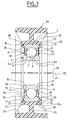
- a bearing 1 comprises an outer ring 2 rotating provided on its bore 2a with an O-ring raceway 3, a ring inner non-rotating 4 provided on its outer surface 4a with a path O-bearing 5, and a row of rolling elements 6, here balls, arranged between the raceway 3 of the outer ring 2 and the raceway 5 of the inner ring 4.
- the rolling elements 6 are kept spaced apart regular circumference by a cage 7.
- the massive inner 4 and outer 2 rings were obtained by conventional machining with removal of material.
- the outer ring 2 is also provided with two radial lateral faces 2b, 2c opposite, and a cylindrical outer surface 2d.
- Two grooves 8 and 9 symmetrical with respect to the radial plane passing through the center of the rolling elements 6, are formed in the bore 2a of the outer ring 2, the groove 8 being adjacent to the side face 2b, the groove 9 being adjacent to the side face 2c.
- the inner ring 4 is also provided with two radial lateral faces 4b, 4c opposite, respectively in the same radial plane as the lateral surfaces 2b and 2c, and a bore 4d.
- Identical sealing members referenced 10, 11 are fixed to the ring exterior 2.
- the sealing members 10, 11 comprise metal reinforcements 12, 13 in the general form of a disc on which parts are overmolded elastic 14, 15 made of elastomer for example.
- the elastic parts 14, 15 are annular and include at their larger diameter end a bead 16, 17.
- the bead 16 of the sealing member 10 is forcibly mounted in the groove 8 of the outer ring 2.
- the bead 17 of the sealing member 11 is mounted at force in the groove 8 of the outer ring 2.
- Each elastic part 14, 15 includes at its small diameter end a sealing lip 18, 19 in contact friction on the outer surface 4a of the inner ring 4.
- the organs seals 10, 11 are of the standard type in the bearings, and guarantee sealing against external pollution and leakage of lubricant, oil or grease, placed inside the bearing 1.
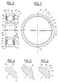
- a chamfer 20 is formed between the outer surface 2d of the ring outer 2 and the side face 2c of the outer ring 2.
- the chamfer is formed along a surface of revolution with an axis 21 parallel to the axis 22 of the bearing 1, and included in the plane of Figure 1.
- the second axis of revolution 21 is offset by relative to the first axis of revolution 22 from a distance of 5% and 15% of the outer diameter of the outer ring 2.
- the chamfer 20 has a width radially varying continuously between a zone 23 of greater width, radially opposite the second axis 21 with respect to the axis 22, and a zone of lesser width 24 diametrically opposite to the area of greatest width 23.
- the chamfer may only be formed on one sector determined angular of the radial lateral surface 2c.
- a chamfer 25 of identical profile to that of the chamfer 20 is formed between the outer surface 2d of the outer ring 2 and the lateral face 2b axially opposite the side face 2c.
- the chamfer 25 is formed on a surface of revolution of axis 26 parallel to the first axis 22, arranged in the same plane as the first and second axes 21 and 22, being symmetrical to axis 21 with respect to axis 22.
- a chamfer 25 having a portion of greater radial width 27 axially opposite the narrower portion 24 of the chamfer 20, and a portion of smaller width 28 axially opposite the portion of greater width 23 of chamfer 20.
- the chamfers 20, 25 are symmetrical with respect to the point belonging to the radial plane passing through the center of the rolling elements 6 and to the first axis 22.
- a roller 29 comprises an axial portion 30 having a bore 30a in contact and in shape with the outside surface 2d of the ring outer 2.
- Beads 31 and 32 extend radially inward from opposite axial ends of the axial portion 30, coming into contact respectively with the side faces 2b and 2c of the outer ring 2.
- the roller 29 comprises a surface of revolution 33 extending obliquely between the bore 30a of the axial portion 30 and the bead 32, having a shape corresponding to the chamfer 20.
- the roller 29 has a surface of revolution 34 extending obliquely between the bore of the axial portion 30 and the bead 31, and of shape concordant with the chamfer 25 of the outer ring 2.
- a radial portion 35 extends outward from the axial portion 30, in the radial plane passing through the center of the rolling elements 6.
- An envelope 36 extends axially from each side symmetrically from the larger diameter area of the radial wall 35.
- the roller 29 can be obtained for example by overmolding a material synthetic on the outer ring 2. This manufacturing process is quick and allows easily obtain the surfaces of revolution 33, 34 of shapes which are consistent with the chamfers 20, 25.
- the beads 31, 32 allow the roller 29 to be secured axially with the outer ring 2.
- the surfaces of revolution 33, 34 of concordant shape with respectively the chamfers 20, 25 allow angularly immobilizing the roller 29 relative to the outer ring 2. Indeed, the rotation of the ring outer 2 relative to the roller 29 is prevented by the jamming effect caused by the contact between the chamfer 20 and the surface of revolution 33 which has an axis of revolution different from the axis of revolution of the surface 2d and of the bore 30a in mutual contact.
- the chamfer 25 cooperates in the same way with the surface of revolution 34.
- a single eccentric chamfer 20 is sufficient for the angular immobilization of the roller 29 and the outer ring 2. However, the formation of a single eccentric chamfer 20 creates an imbalance which can cause vibrations when the ring is rotated outdoor 2.
- the outer ring 2 comprising two eccentric chamfers 20, 25 symmetrical is balanced radially and has no imbalance.
- the ring outer 2 is not entirely axially symmetrical, but has a length reduced axial, so that such asymmetry is of no consequence in terms of vibratory or oscillatory phenomena.
- the chamfers 20, 25 are formed in a manner known per se by machining.
- the formation of eccentric chamfers 20, 25 provides a means angular immobilization without additional machining of the outer ring 2, by compared to a standard ring. This is a slightly different process, but the same type.
- Figure 4 is shown a chamfer 20 of generally frustoconical shape and of straight profile, extending obliquely between the outer surface 2d of the outer ring 2 and the radial lateral surface 2c.
- Figure 5 illustrates a different embodiment.
- a chamfer 37 is curvilinear profile, being on the one hand tangent to the outer surface 2d of the ring outer 2, and on the other hand tangent to the radial lateral surface 2c of the ring outdoor 2.
- a chamfer 38 comprises two frustoconical surfaces of revolution 39, 40 along the same axis.
- the surface 39 extends obliquely, radially inward from the outer surface 2d toward the face 2c.
- the surface 40 extends obliquely, radially outward from the side face 2c, towards the surface outdoor 2d.
- the surfaces 39 and 40 meet to form a rib 41 in profile curvilinear, tangent on one side to the surface 39, and on the other side to the surface 40.
- chamfer profiles are suitable perfectly.
- the profile is adapted to obtain an angular connection of the roller 29 and of the outer ring 2, while allowing a good distribution of the forces.
- two chamfers could be made extending between the surface outer 2d of the outer ring 2 and the side face 2c of the outer ring 2 formed along two surfaces of revolution of axes of revolution 21, 26, so that we obtain two eccentric chamfers offset by 180 °, on the same side of the ring exterior 2 which will then be of axial symmetry.
- the outer ring 2 is no only unbalanced, but also axially balanced.
- the invention applied to a bearing is not limited to a ring rotating outer and an inner non-rotating ring.
- the invention can be easily adapted to a bearing in which the inner ring is rotating, and the non-rotating outer ring.
- a shaft 40 is mounted on a support 41 by means of a bearing 1 comprising an outer non-rotating ring 2 and an inner ring rotating 4, and an interface element 42 disposed between the outer ring 2 and the support 41.
- the outer ring 2 has a cylindrical outer surface 2d extended at its ends by chamfers 20, 25 having as generatices surfaces of revolution of axes of revolution offset from an axis of the cylindrical outer surface 2d.
- the shaft 40 includes a cylindrical outer surface 43 and, at a end, a cylindrical seat 44 having a diameter less than the diameter of the outer surface of the shaft 40.
- a radial shoulder 45 extends between the surface 43 and the range 44.
- the range 44 is provided near the end of the shaft 40 of an annular groove 46 of rectangular section.
- the inner ring 4 of the bearing 1 is adjusted with adequate tightening on the cylindrical surface 44, being in contact by a lateral face 4c with the radial shoulder 45.
- An elastic ring 47 is arranged in the annular groove 46, being located on the side of the inner ring 4 opposite to the shoulder 45. The elastic ring 47 prevents axial movement of the ring inner 4 in a direction opposite to the shoulder 45.
- the support 41 comprises a cylindrical part 48 having a bore 49, a radial portion 50 extending inward from an axial end of the cylindrical part 48, being provided with a central opening, and a flange 51 extending radially outward from an axial end of the portion cylindrical opposite the radial portion 50.
- the radial portion 50 includes in its larger diameter area a axial allowance 52 projecting from the side of the cylindrical part 48, and having a radial bearing surface 53.
- An annular clearance is formed in the support 41 at the end of the bore 49 of the cylindrical part 48 opposite the radial portion 50, and has a internal diameter greater than the diameter of bore 49.
- the annular clearance is partly formed in the cylindrical part 48 and partly in the flange 51.
- the annular clearance includes a cylindrical interior surface 54 and a surface radial 55 extending between the cylindrical inner surface 54 and the bore 49 of the cylindrical part 48.
- the interface element 42 comprises a sleeve 56 of general shape tubular, having an outer surface 57 and at an axial end a surface radial 58, and a flange 59 extending radially outward from a end of the sleeve 56 opposite the radial surface 58.
- the sleeve 56 is molded onto the outer ring 2 so as to come perfectly fit the cylindrical outer surface 2d, the chamfers 20, 25 and part the side faces 2b, 2d of the outer ring 2 of the bearing.
- the sleeve 56 is adjusted in the bore 49 of the cylindrical part 48, the radial surface 58 of free end of the sleeve 56 coming to bear axially on the sa radial surface 53 of the axial allowance 52 of the radial portion 50 of the support 41.
- the sleeve 56 is in axial abutment against the support 41 on the opposite side of the bearing 1 at the shoulder 45 of the shaft 40.
- the bearing 1 is held axially between the radial surface 53 of the radial portion 52 of the support 41 and the shoulder 45 of tree 40.
- the collar 59 of the interface element 42 is housed in the clearance of the support 41 while being adjusted on the inner cylindrical surface 54, and coming into contact with the radial surface 55 of the annular clearance.
- the collar 59 is flush with the surface of the support 41 on the opposite side.
- the end of the shaft 40 comes partly projecting in the central opening of the radial portion 50 of the support 41.
- the outer ring 2 and the sleeve 56 are in contact mainly by surfaces of revolution, while being angularly integral thanks to the presence offset bevels which prevent relative rotation of the outer ring 2 relative to the sleeve 56 by wedging effect, as described previously.
- the sleeve 56 is located substantially radially between the support 41 and the outer ring 2, forming an interface.
- the sleeve 56 is mounted with a Tightening.
- the sleeve 56 can compensate for these variations, to maintain a suitable maintenance of the outer ring 2.
- Such dimensional variations can appear following a heating of the whole. Such heating can occur in an electric motor, a housing of which would include the support 41 and a rotor the shaft 40.
- the sleeve 56 is mounted with sufficient tightening to ensure angular support between the outer ring 2 and the support 41.
- an interface sleeve 56 obtained in a material having a rigidity adapted so that radial deformations caused during mounting between the support 41, the sleeve 56 and the outer ring 2 are concentrated in the sleeve 56, so that the latter compensates for variations dimensional.
- a sleeve 56 made of less rigid material is used than the material used for the support 41 and for the outer ring 2.
- the sleeve 56 forming an interface also makes it possible to absorb vibrations which could be transmitted between the bearing 1 and the support 41.
- provision may be made, in addition to or in replacement of the flange 59, one or more pins spaced circumferentially and projecting in corresponding notches in the support 41.
- provision can be made to replace the flange with a base of any shape allowing an angular immobilization in cooperation with a concordantly shaped housing.
- a part intended for contact with a second part by a surface of revolution is provided with angular immobilization means between the room and a second room, without requiring any additional operation machining.
- a part of general shape of revolution and in particular a part intended for a rapid rotational movement, one easily obtains a balanced piece, free of unbalance.
Landscapes
- Engineering & Computer Science (AREA)
- General Engineering & Computer Science (AREA)
- Mechanical Engineering (AREA)
- Rolling Contact Bearings (AREA)
Abstract
Description
- la figure 1 est une vue en coupe axiale d'un galet à roulement ;
- la figure 2 est une vue en coupe axiale d'un roulement selon la figure 1 ;
- la figure 3 est une vue de face en élévation d'une bague du roulement selon la figure 2 ;
- la figure 4 est une vue en coupe partielle d'un galet ;
- la figure 5 est une vue en coupe partielle d'un second galet ;
- la figure 6 est une vue en coupe partielle d'un troisième galet ; et
- la figure 7 est une vue en coupe d'un ensemble mécanique comprenant un manchon d'interface pour l'adaptation d'un roulement dans un support.
Claims (11)
- Pièce (2) comprenant une surface de révolution (2d) selon un premier axe (22), la surface de révolution (2d) étant prolongée à une extrémité axiale par un chanfrein (20), caractérisé par le fait que le chanfrein (20) possède une génératrice formée par une surface de révolution selon un second axe (21) différent du premier axe (22), pour former un moyen d'immobilisation angulaire lorsque ladite pièce est en contact avec une autre pièce par ladite surface de révolution (2d) et par ledit chanfrein (20).
- Pièce selon la revendication 1, caractérisé par le fait que le second axe (21) est parallèle au premier axe (22).
- Pièce selon la revendication 1 ou 2, caractérisé par le fait qu'elle comprend un second chanfrein (25) possédant une génératrice formée par une surface de révolution selon un troisième axe (26) de révolution différent des premier et second axes (21, 22).
- Pièce selon la revendication 3, caractérisé par le fait que les second et troisième axes (21, 26) sont symétriques par rapport au premier axe (22).
- Pièce selon la revendication 3 ou 4, caractérisé par le fait que le premier chanfrein prolonge la surface de révolution (2d) à partir d'une extrémité axiale de la surface de révolution (2d), le second chanfrein (25) prolongeant la surface de révolution (2d) à partir de l'extrémité axiale opposée.
- Pièce selon l'une quelconque des revendications 3 ou 4, caractérisé le premier chanfrein prolonge la surface de révolution (2d) à partir d'une première extrémité axiale, et le second chanfrein (25) prolonge la surface de révolution (2d) à partir de la même extrémité axiale.
- Pièce selon l'une quelconque des revendications 3 à 6, caractérisé par le fait que les premier et second chanfreins (20, 25) sont symétriques par rapport à un point du premier axe.
- Pièce selon l'une quelconque des revendications précédentes, caractérisé par le fait qu'un chanfrein (20) possède un profil en partie rectiligne et/ou en partie curviligne.
- Ensemble mécanique caractérisé par le fait qu'il comprend une première pièce (2) comprenant une surface de révolution (2d) selon un premier axe (22), prolongée à une extrémité axiale par un chanfrein (20) possédant une génératrice formée par une surface de révolution selon un second axe (21) différent du premier axe (22), et une seconde pièce en contact avec la première pièce par l'intermédiaire de ladite surface de révolution (2d) et dudit chanfrein (20).
- Ensemble mécanique selon la revendication 9, caractérisé par le fait qu'il comprend une bague tournante (2) formant la première pièce, un galet annulaire disposé sur la bague tournante (2) formant la seconde pièce.
- Ensemble mécanique selon la revendication 9, caractérisé par le fait qu'il comprend une bague non tournante (2) formant la première pièce, une bague tournante (4), au moins une rangée d'éléments roulants (6) disposés entre des chemins de roulement des bagues tournante et non tournante (4, 2), et un manchon d'interface formant la seconde pièce et prévu pour être disposé radialement entre la bague tournante et un support en formant une interface.
Applications Claiming Priority (2)
| Application Number | Priority Date | Filing Date | Title |
|---|---|---|---|
| FR0109193A FR2827352B1 (fr) | 2001-07-11 | 2001-07-11 | Piece de revolution, en particulier galet a roulement |
| FR0109193 | 2001-07-11 |
Publications (2)
| Publication Number | Publication Date |
|---|---|
| EP1275862A1 true EP1275862A1 (fr) | 2003-01-15 |
| EP1275862B1 EP1275862B1 (fr) | 2005-09-21 |
Family
ID=8865357
Family Applications (1)
| Application Number | Title | Priority Date | Filing Date |
|---|---|---|---|
| EP20020291656 Expired - Lifetime EP1275862B1 (fr) | 2001-07-11 | 2002-07-03 | Pièce pourvue de moyens d'immobilisation angulaire, et ensemble mécanique associé |
Country Status (3)
| Country | Link |
|---|---|
| EP (1) | EP1275862B1 (fr) |
| DE (1) | DE60206221T2 (fr) |
| FR (1) | FR2827352B1 (fr) |
Cited By (2)
| Publication number | Priority date | Publication date | Assignee | Title |
|---|---|---|---|---|
| US8172065B2 (en) | 2009-06-06 | 2012-05-08 | Aktiebolaget Skf | Bearing assembly |
| CN111536145A (zh) * | 2020-01-14 | 2020-08-14 | 和拓(深圳)工业设计有限公司 | 一种包塑轴承及其制作方法 |
Citations (2)
| Publication number | Priority date | Publication date | Assignee | Title |
|---|---|---|---|---|
| FR2605070A1 (fr) * | 1986-10-09 | 1988-04-15 | Skf Gmbh | Piece de machine annulaire en particulier galet a roulement |
| US5468070A (en) * | 1993-11-05 | 1995-11-21 | Sears Manufacturing Company | Composite roller assembly |
-
2001
- 2001-07-11 FR FR0109193A patent/FR2827352B1/fr not_active Expired - Fee Related
-
2002
- 2002-07-03 DE DE2002606221 patent/DE60206221T2/de not_active Expired - Lifetime
- 2002-07-03 EP EP20020291656 patent/EP1275862B1/fr not_active Expired - Lifetime
Patent Citations (2)
| Publication number | Priority date | Publication date | Assignee | Title |
|---|---|---|---|---|
| FR2605070A1 (fr) * | 1986-10-09 | 1988-04-15 | Skf Gmbh | Piece de machine annulaire en particulier galet a roulement |
| US5468070A (en) * | 1993-11-05 | 1995-11-21 | Sears Manufacturing Company | Composite roller assembly |
Cited By (2)
| Publication number | Priority date | Publication date | Assignee | Title |
|---|---|---|---|---|
| US8172065B2 (en) | 2009-06-06 | 2012-05-08 | Aktiebolaget Skf | Bearing assembly |
| CN111536145A (zh) * | 2020-01-14 | 2020-08-14 | 和拓(深圳)工业设计有限公司 | 一种包塑轴承及其制作方法 |
Also Published As
| Publication number | Publication date |
|---|---|
| FR2827352A1 (fr) | 2003-01-17 |
| EP1275862B1 (fr) | 2005-09-21 |
| FR2827352B1 (fr) | 2003-12-12 |
| DE60206221T2 (de) | 2006-07-13 |
| DE60206221D1 (de) | 2005-10-27 |
Similar Documents
| Publication | Publication Date | Title |
|---|---|---|
| EP1061278B1 (fr) | Dispositif de fixation pour galet à roulement et galet à roulement comportant un tel dispositif | |
| FR3131764A1 (fr) | Dispositif de palier à isolation électrique intégrée, notamment pour moteur ou machine électrique | |
| FR3131765A1 (fr) | Dispositif de palier à isolation électrique intégrée, notamment pour moteur ou machine électrique | |
| FR3131766A1 (fr) | Dispositif de palier à isolation électrique intégrée, notamment pour moteur ou machine électrique | |
| FR3131763A1 (fr) | Dispositif de palier à isolation électrique intégrée, notamment pour moteur ou machine électrique | |
| CA2603248A1 (fr) | Dispositif de galet tendeur | |
| FR3001510A1 (fr) | Cage pour roulement, notamment pour le roulement de direction electrique de vehicule automobile | |
| FR2826413A1 (fr) | Palier a roulement instrumente | |
| EP1433968B1 (fr) | Palier à roulement freiné compact | |
| EP1476760A2 (fr) | Palier a roulement equipe d'un capteur de vitesse de rotation | |
| EP1275862B1 (fr) | Pièce pourvue de moyens d'immobilisation angulaire, et ensemble mécanique associé | |
| FR3159641A1 (fr) | Dispositif de palier à isolation électrique intégrée, notamment pour moteur ou machine électrique | |
| FR3159995A1 (fr) | Dispositif de palier à isolation électrique intégrée, notamment pour moteur ou machine électrique | |
| FR3159996A1 (fr) | Dispositif de palier à isolation électrique intégrée, notamment pour moteur ou machine électrique | |
| FR3156173A1 (fr) | Dispositif de palier à isolation électrique intégrée, notamment pour moteur ou machine électrique | |
| EP1162379B1 (fr) | Galet tendeur de courroie | |
| FR2779787A1 (fr) | Bague de tolerance pour roulement | |
| FR3166414A1 (fr) | Système de palier à isolation électrique intégrée, notamment pour moteur ou machine électrique | |
| FR2886693A1 (fr) | Dispositif anti-rotation pour bague de roulement, et roulement et machine associes | |
| FR2858031A1 (fr) | Dispositif de roue libre, poulie et alternateur equipes d'une roue libre | |
| FR3002092A1 (fr) | Composant de moteur electrique et moteur electrique comprenant un tel composant | |
| FR2826412A1 (fr) | Palier a roulement instrumente | |
| FR3160438A1 (fr) | Dispositif de palier à isolation électrique intégrée, notamment pour moteur ou machine électrique | |
| FR3160439A1 (fr) | Dispositif de palier à isolation électrique intégrée, notamment pour moteur ou machine électrique | |
| FR2886694A1 (fr) | Dispositif anti-rotation pour bague de roulement, et roulement et machine associes |
Legal Events
| Date | Code | Title | Description |
|---|---|---|---|
| PUAI | Public reference made under article 153(3) epc to a published international application that has entered the european phase |
Free format text: ORIGINAL CODE: 0009012 |
|
| AK | Designated contracting states |
Kind code of ref document: A1 Designated state(s): AT BE BG CH CY CZ DE DK EE ES FI FR GB GR IE IT LI LU MC NL PT SE SK TR |
|
| AX | Request for extension of the european patent |
Free format text: AL;LT;LV;MK;RO;SI |
|
| 17P | Request for examination filed |
Effective date: 20030114 |
|
| AKX | Designation fees paid |
Designated state(s): DE FR IT NL |
|
| GRAP | Despatch of communication of intention to grant a patent |
Free format text: ORIGINAL CODE: EPIDOSNIGR1 |
|
| RIN1 | Information on inventor provided before grant (corrected) |
Inventor name: PEROZ, PHILIPPE |
|
| GRAS | Grant fee paid |
Free format text: ORIGINAL CODE: EPIDOSNIGR3 |
|
| GRAA | (expected) grant |
Free format text: ORIGINAL CODE: 0009210 |
|
| AK | Designated contracting states |
Kind code of ref document: B1 Designated state(s): DE FR IT NL |
|
| PG25 | Lapsed in a contracting state [announced via postgrant information from national office to epo] |
Ref country code: NL Free format text: LAPSE BECAUSE OF FAILURE TO SUBMIT A TRANSLATION OF THE DESCRIPTION OR TO PAY THE FEE WITHIN THE PRESCRIBED TIME-LIMIT Effective date: 20050921 |
|
| REF | Corresponds to: |
Ref document number: 60206221 Country of ref document: DE Date of ref document: 20051027 Kind code of ref document: P |
|
| NLV1 | Nl: lapsed or annulled due to failure to fulfill the requirements of art. 29p and 29m of the patents act | ||
| PLBE | No opposition filed within time limit |
Free format text: ORIGINAL CODE: 0009261 |
|
| STAA | Information on the status of an ep patent application or granted ep patent |
Free format text: STATUS: NO OPPOSITION FILED WITHIN TIME LIMIT |
|
| 26N | No opposition filed |
Effective date: 20060622 |
|
| PGFP | Annual fee paid to national office [announced via postgrant information from national office to epo] |
Ref country code: DE Payment date: 20121001 Year of fee payment: 11 |
|
| PGFP | Annual fee paid to national office [announced via postgrant information from national office to epo] |
Ref country code: FR Payment date: 20130730 Year of fee payment: 12 |
|
| PGFP | Annual fee paid to national office [announced via postgrant information from national office to epo] |
Ref country code: IT Payment date: 20130727 Year of fee payment: 12 |
|
| PG25 | Lapsed in a contracting state [announced via postgrant information from national office to epo] |
Ref country code: DE Free format text: LAPSE BECAUSE OF NON-PAYMENT OF DUE FEES Effective date: 20140201 |
|
| REG | Reference to a national code |
Ref country code: DE Ref legal event code: R119 Ref document number: 60206221 Country of ref document: DE Effective date: 20140201 |
|
| REG | Reference to a national code |
Ref country code: FR Ref legal event code: ST Effective date: 20150331 |
|
| PG25 | Lapsed in a contracting state [announced via postgrant information from national office to epo] |
Ref country code: IT Free format text: LAPSE BECAUSE OF NON-PAYMENT OF DUE FEES Effective date: 20140703 |
|
| PG25 | Lapsed in a contracting state [announced via postgrant information from national office to epo] |
Ref country code: FR Free format text: LAPSE BECAUSE OF NON-PAYMENT OF DUE FEES Effective date: 20140731 |