EP1275813A1 - Manual drive system for shutter with epicycle reduction gear - Google Patents
Manual drive system for shutter with epicycle reduction gear Download PDFInfo
- Publication number
- EP1275813A1 EP1275813A1 EP02405503A EP02405503A EP1275813A1 EP 1275813 A1 EP1275813 A1 EP 1275813A1 EP 02405503 A EP02405503 A EP 02405503A EP 02405503 A EP02405503 A EP 02405503A EP 1275813 A1 EP1275813 A1 EP 1275813A1
- Authority
- EP
- European Patent Office
- Prior art keywords
- planetary
- crown
- reducer
- reduction gear
- train
- Prior art date
- Legal status (The legal status is an assumption and is not a legal conclusion. Google has not performed a legal analysis and makes no representation as to the accuracy of the status listed.)
- Granted
Links
- 239000003638 chemical reducing agent Substances 0.000 claims description 25
- 238000004804 winding Methods 0.000 claims description 4
- 238000005096 rolling process Methods 0.000 claims description 2
- 238000004519 manufacturing process Methods 0.000 description 3
- 230000005540 biological transmission Effects 0.000 description 2
- 150000001875 compounds Chemical class 0.000 description 2
- 239000000969 carrier Substances 0.000 description 1
- 230000008878 coupling Effects 0.000 description 1
- 238000010168 coupling process Methods 0.000 description 1
- 238000005859 coupling reaction Methods 0.000 description 1
Images
Classifications
-
- F—MECHANICAL ENGINEERING; LIGHTING; HEATING; WEAPONS; BLASTING
- F16—ENGINEERING ELEMENTS AND UNITS; GENERAL MEASURES FOR PRODUCING AND MAINTAINING EFFECTIVE FUNCTIONING OF MACHINES OR INSTALLATIONS; THERMAL INSULATION IN GENERAL
- F16H—GEARING
- F16H1/00—Toothed gearings for conveying rotary motion
- F16H1/28—Toothed gearings for conveying rotary motion with gears having orbital motion
- F16H1/48—Special means compensating for misalignment of axes, e.g. for equalising distribution of load on the face width of the teeth
-
- E—FIXED CONSTRUCTIONS
- E06—DOORS, WINDOWS, SHUTTERS, OR ROLLER BLINDS IN GENERAL; LADDERS
- E06B—FIXED OR MOVABLE CLOSURES FOR OPENINGS IN BUILDINGS, VEHICLES, FENCES OR LIKE ENCLOSURES IN GENERAL, e.g. DOORS, WINDOWS, BLINDS, GATES
- E06B9/00—Screening or protective devices for wall or similar openings, with or without operating or securing mechanisms; Closures of similar construction
- E06B9/24—Screens or other constructions affording protection against light, especially against sunshine; Similar screens for privacy or appearance; Slat blinds
- E06B9/26—Lamellar or like blinds, e.g. venetian blinds
- E06B9/28—Lamellar or like blinds, e.g. venetian blinds with horizontal lamellae, e.g. non-liftable
- E06B9/30—Lamellar or like blinds, e.g. venetian blinds with horizontal lamellae, e.g. non-liftable liftable
- E06B9/32—Operating, guiding, or securing devices therefor
-
- E—FIXED CONSTRUCTIONS
- E06—DOORS, WINDOWS, SHUTTERS, OR ROLLER BLINDS IN GENERAL; LADDERS
- E06B—FIXED OR MOVABLE CLOSURES FOR OPENINGS IN BUILDINGS, VEHICLES, FENCES OR LIKE ENCLOSURES IN GENERAL, e.g. DOORS, WINDOWS, BLINDS, GATES
- E06B9/00—Screening or protective devices for wall or similar openings, with or without operating or securing mechanisms; Closures of similar construction
- E06B9/56—Operating, guiding or securing devices or arrangements for roll-type closures; Spring drums; Tape drums; Counterweighting arrangements therefor
- E06B9/68—Operating devices or mechanisms, e.g. with electric drive
-
- F—MECHANICAL ENGINEERING; LIGHTING; HEATING; WEAPONS; BLASTING
- F16—ENGINEERING ELEMENTS AND UNITS; GENERAL MEASURES FOR PRODUCING AND MAINTAINING EFFECTIVE FUNCTIONING OF MACHINES OR INSTALLATIONS; THERMAL INSULATION IN GENERAL
- F16H—GEARING
- F16H1/00—Toothed gearings for conveying rotary motion
- F16H1/28—Toothed gearings for conveying rotary motion with gears having orbital motion
- F16H1/46—Systems consisting of a plurality of gear trains each with orbital gears, i.e. systems having three or more central gears
-
- F—MECHANICAL ENGINEERING; LIGHTING; HEATING; WEAPONS; BLASTING
- F16—ENGINEERING ELEMENTS AND UNITS; GENERAL MEASURES FOR PRODUCING AND MAINTAINING EFFECTIVE FUNCTIONING OF MACHINES OR INSTALLATIONS; THERMAL INSULATION IN GENERAL
- F16H—GEARING
- F16H1/00—Toothed gearings for conveying rotary motion
- F16H1/28—Toothed gearings for conveying rotary motion with gears having orbital motion
- F16H2001/2881—Toothed gearings for conveying rotary motion with gears having orbital motion comprising two axially spaced central gears, i.e. ring or sun gear, engaged by at least one common orbital gear wherein one of the central gears is forming the output
Definitions
- the invention relates to a drive device manual of blind, roller shutter or similar, equipped a winding shaft, comprising a reduction gear epicyclic between a manual drive means and the awning winding shaft.
- Such a drive device is known from the EP patent 0 372 803 where it is used for training a Venetian blind by means of a chain driving a chain wheel integral with the planetary gearbox epicyclic simple comprising a fixed crown and a set of satellites carried by a planet carrier constituting the output of the reducer.
- the report of reduction of the reducer is for example from 3 to 1.
- the 3 to 1 ratio mentioned can be obtained by means planetary with 20 teeth, satellites to 10 teeth and a 40-tooth crown.
- the sun gear To switch to a ratio of 2.7 while keeping 10-tooth satellites, the sun gear must have 29 teeth and the crown 49 teeth, i.e. for a module of 1, an increase in outer diameter of the mechanism 9 mm.
- the problem is therefore to obtain a weak transmission with reduced outside diameter, for example a diameter of 20 mm.
- Planetary or planetary reducers are generally used because of the high reduction ratios that can be achieved by such reducers.
- G. Henriot “Gears, design, manufacture, implementation” , 7th edition. In chapter 13.3, pages 545 to 553, Henriot deals with compound trains.
- a compound train is formed by the juxtaposition of two simple planetary trains. Henriot shows the 12 combinations which it is possible to obtain by means of two simple planetary trains of type I, but it is also possible to obtain 12 combinations by combining simple planetary trains of type II, III or IV or by combining the types between them.
- each combination there are therefore 10 possibilities to combine the types, ie II, I-II, I-III, I-IV, II-II, etc., which represents 120 combinations.
- each combination can give rise to 6 different couplings, which gives a total of 720 possibilities.
- a simple type I planetary train is consisting of a planet, a planet carrier and its satellites and a crown.
- the manual drive device is characterized in that the epicyclic reducer consists of the juxtaposition of two simple planetary trains of type I whose planets are mechanically linked so as to be trained simultaneously at the same speed and whose crown of the first planetary train is fixed and the other crown is rotatable, and in this it has a lower reduction ratio or equal to 3.
- the satellites of the two trains are carried by a common planet carrier constituting the inlet of the reducer and the crown of the second train constitutes the output of the reducer.
- the planet carrier of the first planetary gear is secured to the crown of the second train and the planet carrier of the second train constitutes the output of the reducer, the input being on the planets.
- the attached drawing represents the two modes of execution of the invention.
- Figure 1 shows the first embodiment
- Figure 2 shows the second embodiment
- the schematic representation of the reducers is the representation used by G. Henriot.
- the first simple planetary train consists of planetary A1, crown B1, planet carrier U1 with its satellites a1.
- the second planetary train simple consists of the planetary A2, the crown B2, of the planet carrier U2 with its satellites a2.
- the planets A1 and A2 are mechanically rigidly linked so that they rotate at the same speed. They are of course coaxial.
- the U1 and U2 are also linked so as to constitute a unique planet carrier.
- Crown B1 is fixed, that is to say immobilized in rotation.
- Crown B2 is however rotatably mounted and constitutes the outlet S of the reducer directly driving the tube for rolling up the roller shutter or the like.
- Entrance E of the gearbox is done on the planet carrier U1U2.
- This planet carrier can be driven by any means training or operating manual, such as chain, crank, etc.
Landscapes
- Engineering & Computer Science (AREA)
- Structural Engineering (AREA)
- General Engineering & Computer Science (AREA)
- Architecture (AREA)
- Civil Engineering (AREA)
- Mechanical Engineering (AREA)
- Retarders (AREA)
- Blinds (AREA)
- Transmission Devices (AREA)
- Operating, Guiding And Securing Of Roll- Type Closing Members (AREA)
- Building Awnings And Sunshades (AREA)
- Instructional Devices (AREA)
Abstract
Description
L'invention concerne un dispositif d'entraínement manuel de store, volet roulant ou similaire, équipé d'un arbre d'enroulement, comprenant un réducteur épicycloïdal entre un moyen d'entraínement manuel et l'arbre d'enroulement du store.The invention relates to a drive device manual of blind, roller shutter or similar, equipped a winding shaft, comprising a reduction gear epicyclic between a manual drive means and the awning winding shaft.
Un tel dispositif d'entraínement est connu du brevet EP 0 372 803 où il est utilisé pour l'entraínement d'un store vénitien au moyen d'une chaíne entraínant une roue à chaíne solidaire du planétaire d'un réducteur épicycloïdal simple comprenant une couronne fixe et un jeu de satellites porté par un porte-satellites constituant la sortie du réducteur. Le rapport de réduction du réducteur est par exemple de 3 à 1.Such a drive device is known from the EP patent 0 372 803 where it is used for training a Venetian blind by means of a chain driving a chain wheel integral with the planetary gearbox epicyclic simple comprising a fixed crown and a set of satellites carried by a planet carrier constituting the output of the reducer. The report of reduction of the reducer is for example from 3 to 1.
Une des propriétés intéressantes du réducteur épicycloïdal ou planétaire est l'absence de résultante radiale de transmission et par conséquent moins de contrainte sur les composants.One of the interesting properties of the reducer epicyclic or planetary is the absence of a resultant radial transmission and therefore less than constraint on the components.
Dans le document EP 0 372 803, le caractère compact du réducteur planétaire est mis en évidence. Ce caractère compact est toutefois relatif. Dans le dispositif décrit dans le document susmentionné, le réducteur est monté à l'extérieur du carter abritant l'arbre d'enroulement du store vénitien. La disposition du mécanisme réducteur à l'extérieur du carter est non seulement peu esthétique, mais elle nécessite en outre la fabrication de deux produits différents, l'un destiné à être manoeuvré à droite et l'autre destiné à être manoeuvré à gauche. C'est pourquoi il est préférable que le mécanisme réducteur puisse trouver place à l'intérieur du carter de telle sorte que l'on n'a plus d'appendice latéral et que le carter peut être monté dans un sens ou dans l'autre, avec le mécanisme réducteur à son extrémité gauche ou droite.In document EP 0 372 803, the compact nature of the planetary reducer is highlighted. This character compact is however relative. In the device described in the aforementioned document, the reducer is mounted on the outside of the housing housing the shaft of the Venetian blind. The layout of the reduction mechanism outside the casing is not only unattractive, but it also requires the manufacture of two different products, one intended to be maneuvered to the right and the other intended to to be maneuvered to the left. That's why it is preferable that the reduction mechanism can find place inside the housing so that one no longer has a side appendage and the housing can be mounted one way or the other, with the mechanism reducer at its left or right end.
L'expérience montre en outre que pour ce type d'utilisation un rapport de réduction inférieur à 3 est préférable car il confère un certain agrément d'utilisation en raison du déplacement du store que l'on obtient par rapport à l'effort et au mouvement qu'il requiert de l'utilisateur.Experience also shows that for this type a reduction ratio of less than 3 is preferable because it gives a certain approval due to the movement of the blind that one obtains in relation to effort and movement it requires from the user.
Si on désire loger le réducteur à l'intérieur du carter, on est immédiatement confronté à des problèmes de réalisation. En effet, étant donné que l'on désire obtenir un faible rapport de réduction, on est conduit à réduire la différence des diamètres primitifs du planétaire et de la couronne et par conséquent de réduire le diamètre primitif des satellites. Or, si on réduit le diamètre primitif des satellites, il faut soit réduire le nombre de leurs dents', ce qui n'est pas possible à l'infini, soit diminuer leur module, ce qui conduit à les fragiliser. Pour conserver un nombre de dents acceptable sur les satellites, on est alors contraint d'augmenter le nombre de dents de la couronne et par conséquent d'augmenter l'encombrement général du mécanisme. Ainsi, pour un train planétaire du type décrit et représenté dans le document EP 0 372 803, le rapport de 3 à 1 mentionné peut être obtenu au moyen d'un planétaire comportant 20 dents, de satellites à 10 dents et d'une couronne à 40 dents. Pour passer à un rapport de 2,7 en conservant des satellites à 10 dents, le planétaire doit présenter 29 dents et la couronne 49 dents, soit pour un module de 1, une augmentation du diamètre extérieur du mécanisme de 9 mm.If you want to house the reducer inside the housing, we are immediately faced with problems of achievement. Indeed, since we want get a low reduction ratio, one is driven to reduce the difference in the original diameters of the planetary and crown and therefore of reduce the original diameter of the satellites. Now, if we reduces the original diameter of the satellites, either reduce the number of their teeth ', which is not infinitely possible, i.e. decrease their modulus, which leads to weaken them. To keep a number of teeth acceptable on satellites, then we are forced to increase the number of teeth in the crown and therefore increase the overall size of the mechanism. So for a planetary train like described and represented in document EP 0 372 803, the 3 to 1 ratio mentioned can be obtained by means planetary with 20 teeth, satellites to 10 teeth and a 40-tooth crown. To switch to a ratio of 2.7 while keeping 10-tooth satellites, the sun gear must have 29 teeth and the crown 49 teeth, i.e. for a module of 1, an increase in outer diameter of the mechanism 9 mm.
Le problème est donc d'obtenir un rapport de transmission faible avec un diamètre extérieur réduit, par exemple un diamètre de 20 mm.The problem is therefore to obtain a weak transmission with reduced outside diameter, for example a diameter of 20 mm.
Les réducteurs planétaires ou épicycloïdaux sont généralement utilisés en raison des rapports élevés de réduction qu'il est possible d'obtenir au moyen de tels réducteurs. En ce qui concerne les connaissances de l'homme du métier dans le domaine des engrenages, et plus particulièrement des réducteurs planétaires, on peut se référer à l'ouvrage très complet de G. Henriot «Engrenages, conception, fabrication, mise en oeuvre», 7ème édition. Au chapitre 13.3, pages 545 à 553, Henriot traite des trains composés. Un train composé est formé de la juxtaposition de deux trains planétaires simples. Henriot montre les 12 combinaisons qu'il est possible d'obtenir au moyen de deux trains planétaires simples de type I, mais il est aussi possible d'obtenir 12 combinaisons en combinant des trains planétaires simples de type II, III ou IV ou en combinant les types entre eux. Pour chaque combinaison il y a donc 10 possibilités de combiner les types, soit I-I, I-II, I-III, I-IV, II-II, etc., ce qui représente 120 combinaisons. Selon le choix de l'entrée, du point fixe et de la sortie du réducteur, chaque combinaison peut donner naissance à 6 couplages différents, ce qui donne un total de 720 possibilités. Planetary or planetary reducers are generally used because of the high reduction ratios that can be achieved by such reducers. With regard to the knowledge of a person skilled in the art in the field of gears, and more particularly of planetary reducers, reference may be made to the very complete work by G. Henriot "Gears, design, manufacture, implementation" , 7th edition. In chapter 13.3, pages 545 to 553, Henriot deals with compound trains. A compound train is formed by the juxtaposition of two simple planetary trains. Henriot shows the 12 combinations which it is possible to obtain by means of two simple planetary trains of type I, but it is also possible to obtain 12 combinations by combining simple planetary trains of type II, III or IV or by combining the types between them. For each combination there are therefore 10 possibilities to combine the types, ie II, I-II, I-III, I-IV, II-II, etc., which represents 120 combinations. Depending on the choice of input, fixed point and output of the gearbox, each combination can give rise to 6 different couplings, which gives a total of 720 possibilities.
Surmontant les préjugés existants en ce qui concerne la contradiction existant entre les conditions posées, à savoir un rapport de réduction inférieur à 3 et un faible diamètre, l'inventeur s'est demandé s'il n'existait pas une combinaison possible de trains planétaires simples permettant de satisfaire lesdites conditions et présentant une architecture simple de nature à faciliter sa fabrication et à en limiter le coût.Overcoming existing prejudices regarding contradiction existing between the conditions, know a reduction ratio less than 3 and a small diameter, the inventor wondered if there was no possible combination of trains simple planets to satisfy said conditions and presenting a simple architecture of likely to facilitate its manufacture and limit its cost.
Au bout de nombreux calculs et d'opérations de sélection, il a été trouvé que deux réducteurs permettant d'atteindre les objectifs visés. Ces deux réducteurs présentent des caractéristiques communes, à savoir le fait que les trains planétaires simples sont de type I, que les planétaires des deux trains planétaires simples sont liés et qu'une couronne est fixe et l'autre rotative.After numerous calculations and operations of selection it was found that two reducers to achieve the objectives. These two reducers have common characteristics, to know the fact that simple planetary trains are type I, that the planets of the two trains simple planets are related and that a crown is fixed and the other rotary.
Pour mémoire, un train planétaire simple de type I est constitué d'un planétaire, d'un porte-satellites et de ses satellites et d'une couronne.For the record, a simple type I planetary train is consisting of a planet, a planet carrier and its satellites and a crown.
Plus précisément, le dispositif d'entraínement manuel selon l'invention est caractérisé en ce que le réducteur épicycloïdal est constitué de la juxtaposition de deux trains planétaires simples de type I dont les planétaires sont liés mécaniquement de manière à être entraínés simultanément à la même vitesse et dont la couronne du premier train planétaire est fixe et l'autre couronne est rotative, et en ce qu'il présente un rapport de réduction inférieur ou égal à 3.More specifically, the manual drive device according to the invention is characterized in that the epicyclic reducer consists of the juxtaposition of two simple planetary trains of type I whose planets are mechanically linked so as to be trained simultaneously at the same speed and whose crown of the first planetary train is fixed and the other crown is rotatable, and in this it has a lower reduction ratio or equal to 3.
Dans l'un des modes d'exécution, les satellites des deux trains sont portés par un porte-satellites commun constituant l'entrée du réducteur et la couronne du second train constitue la sortie du réducteur.In one embodiment, the satellites of the two trains are carried by a common planet carrier constituting the inlet of the reducer and the crown of the second train constitutes the output of the reducer.
Dans l'autre mode d'exécution, le porte-satellites du premier train planétaire est solidaire de la couronne du second train et le porte-satellites du second train constitue la sortie du réducteur, l'entrée se faisant sur les planétaires.In the other embodiment, the planet carrier of the first planetary gear is secured to the crown of the second train and the planet carrier of the second train constitutes the output of the reducer, the input being on the planets.
Pour un diamètre extérieur du réducteur de 20 mm, il est possible, dans les deux modes d'exécution, d'obtenir un rapport de réduction inférieur à 3, par exemple 2,6.For an outside diameter of the reducer of 20 mm, it is possible, in both modes of execution, obtain a reduction ratio less than 3, by example 2.6.
Le dessin annexé représente les deux modes d'exécution de l'invention.The attached drawing represents the two modes of execution of the invention.
La figure 1 représente le premier mode d'exécution.Figure 1 shows the first embodiment.
La figure 2 représente le second mode d'exécution.Figure 2 shows the second embodiment.
La représentation schématique des réducteurs est la représentation utilisée par G. Henriot.The schematic representation of the reducers is the representation used by G. Henriot.
On a représenté qu'une moitié des portes-satellites et des couronnes relativement à l'axe du réducteur. We have shown that half of the planet carriers and crowns relative to the axis of the reducer.
Dans le mode d'exécution représenté à la figure 1, le premier train planétaire simple est constitué du planétaire A1, de la couronne B1, du porte-satellites U1 avec ses satellites a1. Le second train planétaire simple est constitué du planétaire A2, de la couronne B2, du porte-satellites U2 avec ses satellites a2. Les planétaires A1 et A2 sont liés mécaniquement rigidement de telle sorte qu'ils tournent à la même vitesse. Ils sont bien entendu coaxiaux. Les portes-satellites U1 et U2 sont également liés de manière à constituer un porte-satellites unique. La couronne B1 est fixe, c'est-à-dire immobilisée en rotation. La couronne B2 est par contre montée rotativement et constitue la sortie S du réducteur entraínant directement le tube d'enroulement du volet roulant ou similaire. L'entrée E du réducteur se fait sur le porte-satellites U1U2. Ce porte-satellites peut être entraíné par tout moyen manuel d'entraínement ou de manoeuvre, tel que chaíne, manivelle, etc.In the embodiment shown in Figure 1, the first simple planetary train consists of planetary A1, crown B1, planet carrier U1 with its satellites a1. The second planetary train simple consists of the planetary A2, the crown B2, of the planet carrier U2 with its satellites a2. The planets A1 and A2 are mechanically rigidly linked so that they rotate at the same speed. They are of course coaxial. The U1 and U2 are also linked so as to constitute a unique planet carrier. Crown B1 is fixed, that is to say immobilized in rotation. Crown B2 is however rotatably mounted and constitutes the outlet S of the reducer directly driving the tube for rolling up the roller shutter or the like. Entrance E of the gearbox is done on the planet carrier U1U2. This planet carrier can be driven by any means training or operating manual, such as chain, crank, etc.
Dans un exemple de réalisation de ce premier mode d'exécution, les éléments du réducteur présentent les caractéristiques suivantes :
- planétaire A1 : 11 dents
- satellites a1 : 8 dents
- couronne B1 : 28 dents
- planétaire A2 : 7 dents
- satellites a2 : 11 dents
- couronne B2 : 29 dents
m = 0,53 pour A2, a2, B2 et Dp (b2) = 14,84
pour un rapport de réduction égal à 2,59.In an exemplary embodiment of this first embodiment, the elements of the reducer have the following characteristics:
- planetary A1: 11 teeth
- a1 satellites: 8 teeth
- crown B1: 28 teeth
- planetary A2: 7 teeth
- a2 satellites: 11 teeth
- crown B2: 29 teeth
m = 0.53 for A2, a2, B2 and Dp (b2) = 14.84
for a reduction ratio equal to 2.59.
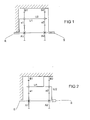
Dans le second mode de réalisation représenté à la figure 2, on retrouve les deux trains planétaires simples A1, B1, a1 et A2, B2, a2 et les deux planétaires A1 et A2 sont à nouveau liés mécaniquement de manière à tourner à la même vitesse. La couronne B1 du premier train planétaire est à nouveau fixe. Le porte-satellites U1 des satellites a1 du premier train est solidaire de la couronne B2 du second train et la sortie du réducteur se fait par le porte-satellites U'2 du second train.In the second embodiment shown in figure 2, we find the two planetary trains simple A1, B1, a1 and A2, B2, a2 and both planets A1 and A2 are again mechanically linked so as to rotate at the same speed. Crown B1 of the first planetary train is again fixed. The planet carrier U1 of the satellites a1 of the first train is secured to the crown B2 of the second train and the output of the gearbox is via the planet carrier U'2 of the second train.
Dans un exemple de réalisation de ce second mode d'exécution, les éléments du réducteur présentent les caractéristiques suivantes :
- planétaire A1 : 7 dents
- satellites a1 : 9 dents
- couronne B1 : 26 dents
- planétaire A2 : 8 dents
- satellites a2 : 10 dents
- couronne B2 : 28 dents
m = 0,53 pour A2, a2, B2 et Dp (B2) = 14,84 pour un rapport de réduction égal à 2,58.In an exemplary embodiment of this second embodiment, the elements of the reducer have the following characteristics:
- planetary A1: 7 teeth
- a1 satellites: 9 teeth
- crown B1: 26 teeth
- planetary A2: 8 teeth
- a2 satellites: 10 teeth
- crown B2: 28 teeth
m = 0.53 for A2, a2, B2 and Dp (B2) = 14.84 for a reduction ratio equal to 2.58.
Claims (3)
Applications Claiming Priority (2)
| Application Number | Priority Date | Filing Date | Title |
|---|---|---|---|
| FR0108411A FR2826400B1 (en) | 2001-06-26 | 2001-06-26 | MANUAL BLIND DRIVE DEVICE INCLUDING AN EPICYCLOIDAL REDUCER |
| FR0108411 | 2001-06-26 |
Publications (2)
| Publication Number | Publication Date |
|---|---|
| EP1275813A1 true EP1275813A1 (en) | 2003-01-15 |
| EP1275813B1 EP1275813B1 (en) | 2008-01-02 |
Family
ID=8864778
Family Applications (1)
| Application Number | Title | Priority Date | Filing Date |
|---|---|---|---|
| EP02405503A Expired - Lifetime EP1275813B1 (en) | 2001-06-26 | 2002-06-19 | Manual drive system for shutter with epicycle reduction gear |
Country Status (8)
| Country | Link |
|---|---|
| US (1) | US6733413B2 (en) |
| EP (1) | EP1275813B1 (en) |
| JP (1) | JP4191434B2 (en) |
| CN (1) | CN1267660C (en) |
| AT (1) | ATE382769T1 (en) |
| DE (1) | DE60224328T2 (en) |
| ES (1) | ES2187398T3 (en) |
| FR (1) | FR2826400B1 (en) |
Families Citing this family (38)
| Publication number | Priority date | Publication date | Assignee | Title |
|---|---|---|---|---|
| US7389806B2 (en) * | 2005-02-24 | 2008-06-24 | Lawrence Kates | Motorized window shade system |
| US20090308543A1 (en) * | 2008-06-13 | 2009-12-17 | Lawrence Kates | Motorized window shade system and mount |
| US8125167B1 (en) | 2008-10-03 | 2012-02-28 | Homerun Holdings Corporation | Motorized barrier adjustment apparatus and method |
| US8375635B2 (en) * | 2009-08-26 | 2013-02-19 | Richard Hellinga | Apparatus for opening and closing overhead sectional doors |
| US8368328B2 (en) * | 2010-02-23 | 2013-02-05 | Homerun Holdings Corporation | Method for operating a motorized roller shade |
| US8299734B2 (en) * | 2010-02-23 | 2012-10-30 | Homerun Holdings Corporation | High efficiency roller shade |
| US8659246B2 (en) | 2010-02-23 | 2014-02-25 | Homerun Holdings Corporation | High efficiency roller shade |
| US9249623B2 (en) | 2010-02-23 | 2016-02-02 | Qmotion Incorporated | Low-power architectural covering |
| US9018868B2 (en) | 2010-02-23 | 2015-04-28 | Qmotion Advanced Shading Systems | High efficiency roller shade and method for setting artificial stops |
| US8575872B2 (en) | 2010-02-23 | 2013-11-05 | Homerun Holdings Corporation | High efficiency roller shade and method for setting artificial stops |
| US9194179B2 (en) | 2010-02-23 | 2015-11-24 | Qmotion Incorporated | Motorized shade with the transmission wire passing through the support shaft |
| US9152032B2 (en) | 2010-02-23 | 2015-10-06 | Qmotion Incorporated | High efficiency motorized roller screen and method of operation |
| CA2800662C (en) | 2010-05-28 | 2019-10-22 | Hunter Douglas Inc. | Architectural opening coverings powered by rotary motors |
| US9289886B2 (en) | 2010-11-04 | 2016-03-22 | Milwaukee Electric Tool Corporation | Impact tool with adjustable clutch |
| BR112014007960A2 (en) | 2011-10-03 | 2017-04-11 | Hunter Douglas | methods and apparatus for architectural opening cover assembly control |
| US20140076115A1 (en) | 2012-09-17 | 2014-03-20 | Homerun Holdings Corporation | Method and apparatus for cutting one or more grooves in a cylindrical element |
| WO2014169093A1 (en) | 2013-04-11 | 2014-10-16 | Qmotion Incorporated | Motorized drapery apparatus, system and method of use |
| CA2828819C (en) | 2012-10-03 | 2020-03-10 | Hunter Douglas Inc. | Methods and apparatus to control an architectural opening covering assembly |
| DE102013217522A1 (en) * | 2013-09-03 | 2015-03-19 | Schaeffler Technologies AG & Co. KG | Planetary coupling transmission |
| WO2015113163A1 (en) | 2014-01-30 | 2015-08-06 | Genesis Advanced Technology Inc. | Roller drive |
| US9801486B2 (en) | 2014-05-19 | 2017-10-31 | Current Products Corp. | Crossover bracket for drapery |
| WO2019051614A1 (en) | 2017-09-16 | 2019-03-21 | Genesis Advanced Technology Inc. | Differential planetary gearbox |
| EP3732071B1 (en) * | 2017-12-29 | 2022-10-26 | Volvo Truck Corporation | A drive system for an engine arrangement |
| CN108386491B (en) * | 2018-04-13 | 2022-11-08 | 王昭平 | Constant linear speed reducer |
| US11457763B2 (en) | 2019-01-18 | 2022-10-04 | Current Products Corp. | Stabilized rotating drapery rod ring system |
| CN110375037A (en) * | 2019-07-25 | 2019-10-25 | 江苏胜牌科技有限公司 | A kind of novel planetary speed reducer |
| WO2021051399A1 (en) | 2019-09-20 | 2021-03-25 | 烟台杰瑞石油装备技术有限公司 | Hydraulic fracturing system for driving plunger pump by using turbine engine |
| US12540575B2 (en) | 2019-09-06 | 2026-02-03 | Yantai Jereh Petroleum Equipment & Technologies Co., Ltd. | Hydraulic fracturing system for driving a plunger pump with a turbine engine and noise reduction thereof |
| US11702919B2 (en) | 2019-09-20 | 2023-07-18 | Yantai Jereh Petroleum Equipment & Technologies Co., Ltd. | Adaptive mobile power generation system |
| CN110485982A (en) | 2019-09-20 | 2019-11-22 | 烟台杰瑞石油装备技术有限公司 | A kind of turbine fracturing unit |
| CN112901292B (en) | 2021-03-30 | 2025-12-09 | 烟台杰瑞石油装备技术有限公司 | Exhaust device, installation method thereof and turbine fracturing equipment |
| US12264568B2 (en) | 2019-09-20 | 2025-04-01 | Yantai Jereh Petroleum Equipment & Technologies Co., Ltd. | Fracturing devices |
| US12163514B2 (en) | 2019-09-20 | 2024-12-10 | Yantai Jereh Petroleum Equipment & Technologies Co., Ltd. | Connecting structure, plunger pump device and generator device |
| US12410695B2 (en) | 2019-09-20 | 2025-09-09 | Yantai Jereh Petroleum Equipment & Technologies Co., Ltd. | Turbine fracturing equipment |
| US11519395B2 (en) | 2019-09-20 | 2022-12-06 | Yantai Jereh Petroleum Equipment & Technologies Co., Ltd. | Turbine-driven fracturing system on semi-trailer |
| US12234712B2 (en) | 2019-09-20 | 2025-02-25 | Yantai Jereh Petroleum Equipment & Technologies Co., Ltd. | Adaptive mobile power generation system |
| US12065916B2 (en) | 2019-09-20 | 2024-08-20 | Yantai Jereh Petroleum Equipment & Technologies Co., Ltd. | Hydraulic fracturing system for driving a plunger pump with a turbine engine |
| CN113047916A (en) | 2021-01-11 | 2021-06-29 | 烟台杰瑞石油装备技术有限公司 | Switchable device, well site, control method thereof, switchable device, and storage medium |
Citations (1)
| Publication number | Priority date | Publication date | Assignee | Title |
|---|---|---|---|---|
| EP0372803A1 (en) * | 1988-12-06 | 1990-06-13 | Hunter Douglas Industries B.V. | Drive mechanism for venetian blind |
Family Cites Families (6)
| Publication number | Priority date | Publication date | Assignee | Title |
|---|---|---|---|---|
| IT209412Z2 (en) * | 1986-01-15 | 1988-10-05 | Somfy | ROTATION DRIVE DEVICE OF THE WINDING TUBE OF A ROLLER SHUTTER, SHUTTER OR SIMILAR. |
| JPS63109826A (en) * | 1986-10-25 | 1988-05-14 | エスエム工業株式会社 | Curtain opening and closing drive apparatus |
| FR2742834B1 (en) * | 1995-12-22 | 1998-02-13 | Technigroup | PLANETARY REDUCER FOR BLIND DEVICES, ROLLER SHUTTERS AND THE LIKE |
| US5931212A (en) * | 1997-07-15 | 1999-08-03 | Wayne-Dalton Corp. | Motorized operator for doors |
| JP2001159434A (en) * | 1999-12-01 | 2001-06-12 | Wakayama Nainenki Co Ltd | Emergency brake device |
| US6422965B1 (en) * | 2000-04-20 | 2002-07-23 | Overhead Door Corporation | Door operator unit |
-
2001
- 2001-06-26 FR FR0108411A patent/FR2826400B1/en not_active Expired - Fee Related
-
2002
- 2002-06-18 US US10/174,251 patent/US6733413B2/en not_active Expired - Fee Related
- 2002-06-19 EP EP02405503A patent/EP1275813B1/en not_active Expired - Lifetime
- 2002-06-19 ES ES02405503T patent/ES2187398T3/en not_active Expired - Lifetime
- 2002-06-19 DE DE60224328T patent/DE60224328T2/en not_active Expired - Lifetime
- 2002-06-19 AT AT02405503T patent/ATE382769T1/en not_active IP Right Cessation
- 2002-06-24 JP JP2002182415A patent/JP4191434B2/en not_active Expired - Fee Related
- 2002-06-26 CN CNB02124944XA patent/CN1267660C/en not_active Expired - Fee Related
Patent Citations (1)
| Publication number | Priority date | Publication date | Assignee | Title |
|---|---|---|---|---|
| EP0372803A1 (en) * | 1988-12-06 | 1990-06-13 | Hunter Douglas Industries B.V. | Drive mechanism for venetian blind |
Also Published As
| Publication number | Publication date |
|---|---|
| FR2826400B1 (en) | 2004-08-27 |
| CN1393647A (en) | 2003-01-29 |
| ATE382769T1 (en) | 2008-01-15 |
| JP4191434B2 (en) | 2008-12-03 |
| FR2826400A1 (en) | 2002-12-27 |
| US6733413B2 (en) | 2004-05-11 |
| CN1267660C (en) | 2006-08-02 |
| ES2187398T1 (en) | 2003-06-16 |
| ES2187398T3 (en) | 2008-05-16 |
| JP2003090394A (en) | 2003-03-28 |
| US20030004029A1 (en) | 2003-01-02 |
| EP1275813B1 (en) | 2008-01-02 |
| DE60224328D1 (en) | 2008-02-14 |
| DE60224328T2 (en) | 2008-12-11 |
Similar Documents
| Publication | Publication Date | Title |
|---|---|---|
| EP1275813B1 (en) | Manual drive system for shutter with epicycle reduction gear | |
| FR2808573A1 (en) | CONTINUOUSLY GRADUALLY VARIABLE GEARBOX FOR VEHICLES | |
| FR2487934A1 (en) | CLUTCH CLUTCH FOR MOTORCYCLE | |
| EP0658705B1 (en) | Speed-reducing mechanism and transmission device with two ranges for a motor vehicle | |
| EP0863331B1 (en) | Planetary speed reducer with opposing oblique teeth | |
| FR2853613A1 (en) | Transmission system for driving vehicle power steering, has two drive trains with notched belts, where each belt couples pulley and ring gear, and teeth of drive train presents gap with respect to one another | |
| WO2020052859A1 (en) | Mechanical reduction gearing and associated geared motor | |
| EP0936382B1 (en) | Mechanical device for rotational speed reduction | |
| WO2019206836A1 (en) | Bicycle gearbox | |
| WO2019206835A1 (en) | Transmission assembly for cycles | |
| EP0188164A1 (en) | Steering unit for an automotive vehicle with a fixed central cushion | |
| EP0281847B1 (en) | Dental hand piece | |
| FR2855229A1 (en) | GEARBOX WITH TWO CLUTCHES AND TWO SECONDARY SHAFTS | |
| EP0014139A2 (en) | Continuously variable transmission | |
| FR3117183A1 (en) | Transmission device for electric vehicle and vehicle equipped with such a transmission | |
| EP0832377A1 (en) | Gearbox drive line | |
| FR2485669A1 (en) | Cycloidal bevel gear reduction train - uses double inclined input gear enmeshing with coaxial output gear and fixed concentric, outer gear | |
| FR2806456A1 (en) | Self-regulating variable mechanical transmission, for automobiles, uses differential gear to connect input shaft to epicyclic gear train driving output shaft | |
| CA2925055A1 (en) | Angular speed reduction device | |
| FR2841313A1 (en) | Automobile automatic six gear gearbox comprises three gear trains between input shaft constituting first power path and parallel intermediate shaft comprising second power path | |
| FR2533988A2 (en) | Motor-propulsion group comprising a drive motor and a hydrodynamic brake. | |
| FR2912694A1 (en) | Power distribution transmission for motor vehicle, has rotor shaft coaxial to axle, arranged at end opposite to shaft, and rotationally assembled on electric machine cases, where one of cases is fixed on gear-box in dismountable manner | |
| FR2871838A1 (en) | Opening frame e.g. roller blind, closing and opening device, has reduction unit that is irreversible and constitutes braking unit and epicycloidal reduction stage having movable ring gear constituting output shaft for stage | |
| EP1375961A2 (en) | 6-speed automatic transmission for vehicles | |
| BE471072A (en) |
Legal Events
| Date | Code | Title | Description |
|---|---|---|---|
| PUAI | Public reference made under article 153(3) epc to a published international application that has entered the european phase |
Free format text: ORIGINAL CODE: 0009012 |
|
| AK | Designated contracting states |
Kind code of ref document: A1 Designated state(s): AT BE CH CY DE DK ES FI FR GB GR IE IT LI LU MC NL PT SE TR |
|
| AX | Request for extension of the european patent |
Free format text: AL;LT;LV;MK;RO;SI |
|
| RAP1 | Party data changed (applicant data changed or rights of an application transferred) |
Owner name: SOMFY |
|
| 17P | Request for examination filed |
Effective date: 20030623 |
|
| AKX | Designation fees paid |
Designated state(s): AT BE CH CY DE DK ES FI FR GB GR IE IT LI LU MC NL PT SE TR |
|
| RAP1 | Party data changed (applicant data changed or rights of an application transferred) |
Owner name: SOMFY SAS |
|
| GRAP | Despatch of communication of intention to grant a patent |
Free format text: ORIGINAL CODE: EPIDOSNIGR1 |
|
| GRAS | Grant fee paid |
Free format text: ORIGINAL CODE: EPIDOSNIGR3 |
|
| GRAA | (expected) grant |
Free format text: ORIGINAL CODE: 0009210 |
|
| AK | Designated contracting states |
Kind code of ref document: B1 Designated state(s): AT BE CH CY DE DK ES FI FR GB GR IE IT LI LU MC NL PT SE TR |
|
| REG | Reference to a national code |
Ref country code: GB Ref legal event code: FG4D Free format text: NOT ENGLISH |
|
| REG | Reference to a national code |
Ref country code: IE Ref legal event code: FG4D Free format text: LANGUAGE OF EP DOCUMENT: FRENCH |
|
| REG | Reference to a national code |
Ref country code: CH Ref legal event code: EP |
|
| REF | Corresponds to: |
Ref document number: 60224328 Country of ref document: DE Date of ref document: 20080214 Kind code of ref document: P |
|
| REG | Reference to a national code |
Ref country code: ES Ref legal event code: FG2A Ref document number: 2187398 Country of ref document: ES Kind code of ref document: T3 |
|
| GBV | Gb: ep patent (uk) treated as always having been void in accordance with gb section 77(7)/1977 [no translation filed] | ||
| PG25 | Lapsed in a contracting state [announced via postgrant information from national office to epo] |
Ref country code: FI Free format text: LAPSE BECAUSE OF FAILURE TO SUBMIT A TRANSLATION OF THE DESCRIPTION OR TO PAY THE FEE WITHIN THE PRESCRIBED TIME-LIMIT Effective date: 20080102 |
|
| PG25 | Lapsed in a contracting state [announced via postgrant information from national office to epo] |
Ref country code: AT Free format text: LAPSE BECAUSE OF FAILURE TO SUBMIT A TRANSLATION OF THE DESCRIPTION OR TO PAY THE FEE WITHIN THE PRESCRIBED TIME-LIMIT Effective date: 20080102 |
|
| PG25 | Lapsed in a contracting state [announced via postgrant information from national office to epo] |
Ref country code: PT Free format text: LAPSE BECAUSE OF FAILURE TO SUBMIT A TRANSLATION OF THE DESCRIPTION OR TO PAY THE FEE WITHIN THE PRESCRIBED TIME-LIMIT Effective date: 20080602 |
|
| REG | Reference to a national code |
Ref country code: IE Ref legal event code: FD4D |
|
| PG25 | Lapsed in a contracting state [announced via postgrant information from national office to epo] |
Ref country code: DK Free format text: LAPSE BECAUSE OF FAILURE TO SUBMIT A TRANSLATION OF THE DESCRIPTION OR TO PAY THE FEE WITHIN THE PRESCRIBED TIME-LIMIT Effective date: 20080102 Ref country code: IE Free format text: LAPSE BECAUSE OF FAILURE TO SUBMIT A TRANSLATION OF THE DESCRIPTION OR TO PAY THE FEE WITHIN THE PRESCRIBED TIME-LIMIT Effective date: 20080102 Ref country code: SE Free format text: LAPSE BECAUSE OF FAILURE TO SUBMIT A TRANSLATION OF THE DESCRIPTION OR TO PAY THE FEE WITHIN THE PRESCRIBED TIME-LIMIT Effective date: 20080402 |
|
| PLBE | No opposition filed within time limit |
Free format text: ORIGINAL CODE: 0009261 |
|
| STAA | Information on the status of an ep patent application or granted ep patent |
Free format text: STATUS: NO OPPOSITION FILED WITHIN TIME LIMIT |
|
| 26N | No opposition filed |
Effective date: 20081003 |
|
| BERE | Be: lapsed |
Owner name: SOMFY SAS Effective date: 20080630 |
|
| PG25 | Lapsed in a contracting state [announced via postgrant information from national office to epo] |
Ref country code: GB Free format text: LAPSE BECAUSE OF FAILURE TO SUBMIT A TRANSLATION OF THE DESCRIPTION OR TO PAY THE FEE WITHIN THE PRESCRIBED TIME-LIMIT Effective date: 20080102 |
|
| PG25 | Lapsed in a contracting state [announced via postgrant information from national office to epo] |
Ref country code: MC Free format text: LAPSE BECAUSE OF NON-PAYMENT OF DUE FEES Effective date: 20080630 |
|
| REG | Reference to a national code |
Ref country code: CH Ref legal event code: PL |
|
| PG25 | Lapsed in a contracting state [announced via postgrant information from national office to epo] |
Ref country code: BE Free format text: LAPSE BECAUSE OF NON-PAYMENT OF DUE FEES Effective date: 20080630 |
|
| PG25 | Lapsed in a contracting state [announced via postgrant information from national office to epo] |
Ref country code: LI Free format text: LAPSE BECAUSE OF NON-PAYMENT OF DUE FEES Effective date: 20080630 Ref country code: CH Free format text: LAPSE BECAUSE OF NON-PAYMENT OF DUE FEES Effective date: 20080630 |
|
| PG25 | Lapsed in a contracting state [announced via postgrant information from national office to epo] |
Ref country code: CY Free format text: LAPSE BECAUSE OF FAILURE TO SUBMIT A TRANSLATION OF THE DESCRIPTION OR TO PAY THE FEE WITHIN THE PRESCRIBED TIME-LIMIT Effective date: 20080102 |
|
| PG25 | Lapsed in a contracting state [announced via postgrant information from national office to epo] |
Ref country code: LU Free format text: LAPSE BECAUSE OF NON-PAYMENT OF DUE FEES Effective date: 20080619 |
|
| PG25 | Lapsed in a contracting state [announced via postgrant information from national office to epo] |
Ref country code: TR Free format text: LAPSE BECAUSE OF FAILURE TO SUBMIT A TRANSLATION OF THE DESCRIPTION OR TO PAY THE FEE WITHIN THE PRESCRIBED TIME-LIMIT Effective date: 20080102 |
|
| PG25 | Lapsed in a contracting state [announced via postgrant information from national office to epo] |
Ref country code: GR Free format text: LAPSE BECAUSE OF FAILURE TO SUBMIT A TRANSLATION OF THE DESCRIPTION OR TO PAY THE FEE WITHIN THE PRESCRIBED TIME-LIMIT Effective date: 20080403 |
|
| PGFP | Annual fee paid to national office [announced via postgrant information from national office to epo] |
Ref country code: ES Payment date: 20120625 Year of fee payment: 11 |
|
| PGFP | Annual fee paid to national office [announced via postgrant information from national office to epo] |
Ref country code: IT Payment date: 20130619 Year of fee payment: 12 |
|
| PG25 | Lapsed in a contracting state [announced via postgrant information from national office to epo] |
Ref country code: IT Free format text: LAPSE BECAUSE OF NON-PAYMENT OF DUE FEES Effective date: 20140619 |
|
| REG | Reference to a national code |
Ref country code: ES Ref legal event code: FD2A Effective date: 20150724 |
|
| PG25 | Lapsed in a contracting state [announced via postgrant information from national office to epo] |
Ref country code: ES Free format text: LAPSE BECAUSE OF NON-PAYMENT OF DUE FEES Effective date: 20140620 |
|
| REG | Reference to a national code |
Ref country code: FR Ref legal event code: PLFP Year of fee payment: 15 |
|
| PGFP | Annual fee paid to national office [announced via postgrant information from national office to epo] |
Ref country code: NL Payment date: 20160512 Year of fee payment: 15 |
|
| PGFP | Annual fee paid to national office [announced via postgrant information from national office to epo] |
Ref country code: DE Payment date: 20160525 Year of fee payment: 15 |
|
| PGFP | Annual fee paid to national office [announced via postgrant information from national office to epo] |
Ref country code: FR Payment date: 20160607 Year of fee payment: 15 |
|
| REG | Reference to a national code |
Ref country code: DE Ref legal event code: R119 Ref document number: 60224328 Country of ref document: DE |
|
| REG | Reference to a national code |
Ref country code: NL Ref legal event code: MM Effective date: 20170701 |
|
| PG25 | Lapsed in a contracting state [announced via postgrant information from national office to epo] |
Ref country code: NL Free format text: LAPSE BECAUSE OF NON-PAYMENT OF DUE FEES Effective date: 20170701 |
|
| REG | Reference to a national code |
Ref country code: FR Ref legal event code: ST Effective date: 20180228 |
|
| PG25 | Lapsed in a contracting state [announced via postgrant information from national office to epo] |
Ref country code: DE Free format text: LAPSE BECAUSE OF NON-PAYMENT OF DUE FEES Effective date: 20180103 |
|
| PG25 | Lapsed in a contracting state [announced via postgrant information from national office to epo] |
Ref country code: FR Free format text: LAPSE BECAUSE OF NON-PAYMENT OF DUE FEES Effective date: 20170630 |