EP1275546A2 - Device for driving curtains mounted on motor vehicles and the like - Google Patents
Device for driving curtains mounted on motor vehicles and the like Download PDFInfo
- Publication number
- EP1275546A2 EP1275546A2 EP02015185A EP02015185A EP1275546A2 EP 1275546 A2 EP1275546 A2 EP 1275546A2 EP 02015185 A EP02015185 A EP 02015185A EP 02015185 A EP02015185 A EP 02015185A EP 1275546 A2 EP1275546 A2 EP 1275546A2
- Authority
- EP
- European Patent Office
- Prior art keywords
- curtain
- driving
- actuator
- coupled
- box
- Prior art date
- Legal status (The legal status is an assumption and is not a legal conclusion. Google has not performed a legal analysis and makes no representation as to the accuracy of the status listed.)
- Granted
Links
- 230000008878 coupling Effects 0.000 claims description 14
- 238000010168 coupling process Methods 0.000 claims description 14
- 238000005859 coupling reaction Methods 0.000 claims description 14
- 238000005553 drilling Methods 0.000 claims description 9
- 230000005540 biological transmission Effects 0.000 claims description 3
- 238000010276 construction Methods 0.000 claims description 3
- 230000002950 deficient Effects 0.000 claims description 2
- 238000013459 approach Methods 0.000 description 2
- 230000000712 assembly Effects 0.000 description 1
- 238000000429 assembly Methods 0.000 description 1
- 230000002860 competitive effect Effects 0.000 description 1
- 238000006073 displacement reaction Methods 0.000 description 1
- 238000012986 modification Methods 0.000 description 1
- 230000004048 modification Effects 0.000 description 1
Images


Classifications
-
- B—PERFORMING OPERATIONS; TRANSPORTING
- B60—VEHICLES IN GENERAL
- B60J—WINDOWS, WINDSCREENS, NON-FIXED ROOFS, DOORS, OR SIMILAR DEVICES FOR VEHICLES; REMOVABLE EXTERNAL PROTECTIVE COVERINGS SPECIALLY ADAPTED FOR VEHICLES
- B60J11/00—Removable external protective coverings specially adapted for vehicles or parts of vehicles, e.g. parking covers
Definitions
- the present invention relates to a device for driving curtains mounted on motor vehicles and the like.
- curtains have been already specifically designed comprising oleodynamically driven devices for performing the typical movements necessary to extend and fold again the curtains, that is the overturning or tilting of the curtain box, the opening of the curtain box cover, and the extending of the folded curtains.
- the aim of the present invention is to overcome the above mentioned drawbacks, by providing a driving device for driving and handling curtains mounted on motor vehicles and the like, allowing to adjust or control at will the curtain opening step, thereby easily fitting all the contingent use applications.
- a main object of the present invention is to provide such a driving device which, in a case of a failure of conventional driving or operating devices, allows to operate with one of a plurality of outer elements adapted to control the curtain movements.
- Another object of the present invention is to provide such a driving device which, owing to its specifically designed constructional features, is very reliable and safe in operation.
- Yet another object of the present invention is to provide such a curtain driving device which can be easily made and which, furthermore is very competitive from a mere economic standpoint.
- a driving device for driving curtains mounted on motor vehicles and the like comprising a curtain holding box associated with overturning means and housing herein means for opening and closing the box cover and means for extending said curtains, characterized in that said device further comprises adjusting means for adjusting the opening of the curtains, and coupling means for driving all said means, through an outer control device to be used in an emergency condition.
- the device for driving curtains, mounted on motor vehicles and the like comprises a curtain holding box, generally indicated by the reference number 1, which is coupled to a motor vehicle 2.
- the curtain box 1 comprises a bottom element or frame 3, to which is pivoted a cover 4, allowing to house inside the curtain box 1 overturning means for overturning it, comprising one or more overturning or turning-over actuators 10, pivoted between the bottom element 3 and curtain body 11, which, in turn, is pivoted to a frame 3 which can be applied to the motor vehicle.
- two actuators 20 arranged at the opposite side end portions of the curtain box 1 and applied to the latter.
- Said actuators 20 are mutually coupled by a flexible shaft 20' allowing to simultaneously drive the cover 4 of the curtain box holding the curtain body 11 therein, even if one of the actuators 20 does not operate or is defective.
- the two mentioned actuators 20 can be replaced by a single central motor, coupled to the raising actuators 20 through one or more transmission shafts 20', preferably flexible transmission shafts.
- Figure 11 is a detail view showing the actuators 10 for overturning or turning over the curtain box and curtain body.
- the fan arms 31 are in turn coupled to a curtain shaft 33, to which is moreover coupled a gear wheel 34 therewith curtain extending means cooperate.
- the curtain extending means comprise a rack 35 (see figure 6), driven by an actuator 36 allowing to translate the rack 35 and, accordingly, to open and close the curtain.
- the actuator 36, and the means for turning over the curtain box 1 and opening and closing the curtain box cover 4 comprise a motor 40 (see figures 5 and 6), which is provided with coupling elements 70 for coupling with an outer control device, which can also comprise a hand-held drilling device 51, provided with a built-in power supply accumulator.
- This outer control device can also comprise a crank or other manually operated tool.
- the coupling elements are connected by a flexible element 70 and a fitting 71 to an end-piece 52 of the motor 40 (see figure 6).
- the end-piece 52 in a case of a failure of the motor, can be driven so as to rotatively drive (see figure 8) a screw 55 engaging with a bush 56 coupled to a stem 57 comprising a tubular element projecting from a cylinder 36.
- the actuator 36 can be any desired suitable type of actuator with the screw, of a roller-ball-triangular or trapezoidal type and the like.
- Figures 14 and 15 show an urging spring 91, which can be applied to the actuators 20 controlling the raising and lowering movements of the curtain box 1 and adapted to properly tilt the curtain box 1.
- adjusting means are provided for adjusting the curtain opening, which adjusting means are shown in figures 9 and 10 and practically comprise an adjusting motor 60 operating on a threaded bar 61 (of a roller-ball-trapezoidal-triangular type and so on) therewith is engaged a scroll 62 which in turn coupled to the curtain supporting frame 30, so as to adjust the position of the latter.
- a clutch element 65 for a recessed head wrench which can be coupled to a hand held drilling device 51 or any other outer element, even of a manual type, allowing to operate the curtain bearing or supporting frame 30, thereby allowing the curtain to be sidewise displaced, owing to the engagement of the scroll 62, to be used in an emergency condition.
- connection of the hand-held drilling device 51 and motors for driving the elements for opening and closing the curtain are performed by flexible tubes, shafts or fittings.
- Said actuator 20 comprises a worm screw 83 engaging with an helicoidal gear wheel 84 supported by supporting bearings 85.
- Said actuators 20 can be controlled either by an electric motor 81 or by an oleodynamic or pneumatic motor.
- Said actuator 20 comprises, at one end portion thereof, a flexible shaft coupling the two actuators, respectively the right and left actuators.
- the screw (of a roller-ball-trapezoidal-triangular and so on type) 87 controlling the withdrawing movement of the rod 88 is encompassed by a guide tube 89, having bearings 90, therealong the rod 88 axially slide during its reciprocating rectilinear movement.
- Said spring 91 which represents an additional urging element, is arranged parallel to the actuator 20 and cooperates with the latter for raising and lowering the curtain box 1, so as to reduce, the power necessary for performing this operation.
- This turning over actuator comprises a driving motor 92, preferably an electric motor, operating a multi-stage worm screw reducing unit 97, therefrom an emergency shaft 93 projects.
- the latter can be operated from the outside by manual operating tools or an electric tool comprising a drilling tool and battery assembly, to which a tool adapted to engage with the emergency shaft contour 93 can be applied.
- the multi-stage worm reducing unit 97 is coupled to a helical screw or worm 94, which rotates and is supported by bearings 100.
- This worm screw 94 drives a further screw 95 which causes the stem 101 to be axially inwardly and outwardly displaced.
- the rod 101 in particular, is encompassed by a guide tube 96, which holds said rod 101 properly located so as to provide, as it is operated, a reciprocating rectilinear movement, by entering and exiting from said guide tube 96.
- the screw for withdrawing the rod supports, in turn, a scroll 99.
- the invention provides a driving device for driving curtains mounted on motor vehicles and the like which, at first, allows to operate the curtain from the outside, even by using manually operated tools and means, in an emergency condition.
- the inventive device moreover, allows to adjust at will, within comparatively broad ranges, the curtain opening region, thereby it can be easily fitted to all the contingent situations.
- the actuator-spring coupling allows to reduce the control motor power, necessary for controlling the individual movements, thereby providing a great power saving, without requiring the use of an additional power supply battery.
- the curtain driving means in particular, can be selected from different types of driving means, i.e. they can comprise electric, hydraulic or pneumatic motors.
- the used materials, as well as the contingent size and shapes can be any, depending on requirements.
Landscapes
- Engineering & Computer Science (AREA)
- Mechanical Engineering (AREA)
- Curtains And Furnishings For Windows Or Doors (AREA)
- Operating, Guiding And Securing Of Roll- Type Closing Members (AREA)
- Power-Operated Mechanisms For Wings (AREA)
- Forklifts And Lifting Vehicles (AREA)
- Automobile Manufacture Line, Endless Track Vehicle, Trailer (AREA)
- Vehicle Waterproofing, Decoration, And Sanitation Devices (AREA)
Abstract
Description
- The present invention relates to a device for driving curtains mounted on motor vehicles and the like.
- As is known, on commercial use motor vehicles are frequently applied box assemblies for holding therein folded curtains, which, for use, are opened so as to provide a broad covered space on the front, on the side and the rear of the motor vehicle.
- To that end, curtains have been already specifically designed comprising oleodynamically driven devices for performing the typical movements necessary to extend and fold again the curtains, that is the overturning or tilting of the curtain box, the opening of the curtain box cover, and the extending of the folded curtains.
- Prior approaches, however, are affected by problems, deriving from the impossibility of adjusting at will the space which is covered by an extended curtain; moreover, a further drawback of the prior art approaches is that the oleodynamically operated devices are driven by electric apparatus which are coupled to the motor vehicle battery supply.
- Thus, if one of the above mentioned devices does not proper operate, or if the motor vehicle battery is not sufficiently charged, that it is not possible to properly operate the curtains, with the related difficulties.
- Accordingly, the aim of the present invention is to overcome the above mentioned drawbacks, by providing a driving device for driving and handling curtains mounted on motor vehicles and the like, allowing to adjust or control at will the curtain opening step, thereby easily fitting all the contingent use applications.
- Within the scope of the above mentioned aim, a main object of the present invention is to provide such a driving device which, in a case of a failure of conventional driving or operating devices, allows to operate with one of a plurality of outer elements adapted to control the curtain movements.
- Another object of the present invention is to provide such a driving device which, owing to its specifically designed constructional features, is very reliable and safe in operation.
- Yet another object of the present invention is to provide such a curtain driving device which can be easily made and which, furthermore is very competitive from a mere economic standpoint.
- According to one aspect of the present invention, the above mention aim and objects, as well as yet other objects, which will become more apparent hereinafter, are achieved by a driving device for driving curtains mounted on motor vehicles and the like, comprising a curtain holding box associated with overturning means and housing herein means for opening and closing the box cover and means for extending said curtains, characterized in that said device further comprises adjusting means for adjusting the opening of the curtains, and coupling means for driving all said means, through an outer control device to be used in an emergency condition.
- Further characteristics and advantages of the present invention will become more apparent hereinafter from the following detailed disclosure of a preferred, though not exclusive, embodiment of a driving device for driving curtains mounted on motor vehicles and the like, which is illustrated, by way of an indicative, but not limitative, example, in the accompanying drawings, where:
- Figure 1 is a schematic view illustrating the curtain operation step, performed by an outer control device designed for controlling the overturning movement of the curtain box;
- Figure 2 is a schematic perspective view illustrating the curtain box in an overturned condition, ready for starting the opening of the curtain;
- Figure 3 is a further schematic perspective view illustrating the overturned box, before starting the box cover opening step;
- Figure 4 shows the box cover in an open position thereof;
- Figure 5 shows the curtain opening operating step;
- Figure 6 shows the outer control means for controlling, from the outside, the opening and closing of the curtain, to be used in an emergency condition;
- Figure 7 illustrates a rack-gear wheel coupling for performing the curtain opening movement;
- Figure 8 is a schematic cross-sectional view illustrating the curtain extending means;
- Figure 9 is a further schematic view illustrating an adjusting operating step for adjusting the curtain opening, to be used in an emergency condition;
- Figure 10 is a further cross-sectional schematic view illustrating the adjusting means for adjusting or controlling the curtain opening, so as to change the front and rear width of said curtain;
- Figure 11 shows the curtain box and control elements for controlling the raising of said curtain box, by coupling, through a flexible shaft, the two motors arranged at the end portions of the curtain box;
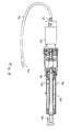
- Figure 12 shows an electric motor having a motor shaft including a gripping element for a manual emergency operation and including moreover a shaft for coupling it to a flexible shaft for raising and lowering the curtain box, to be coupled with a flexible shaft;
- Figure 13 shows a further view of that same actuator for raising and lowering the curtain box, which is shown in a cross-sectional view;
- Figures 14 and 15 are, respectively, a side cross-sectioned view and a perspective view showing an actuator for raising the curtain box, having a spring, operating as a pushing aiding element, for reducing the operating power necessary for driving the curtain box as it is opened and closed; and
- Figure 16 is a detail view of an
overturning actuator designed for a pivot connection
between the
bottom base 3 and thecurtain body 11. -
- With reference to the number references of the above mentioned figures, the device for driving curtains, mounted on motor vehicles and the like, according to the present invention, comprises a curtain holding box, generally indicated by the
reference number 1, which is coupled to amotor vehicle 2. - The
curtain box 1 comprises a bottom element orframe 3, to which is pivoted acover 4, allowing to house inside thecurtain box 1 overturning means for overturning it, comprising one or more overturning or turning-overactuators 10, pivoted between thebottom element 3 andcurtain body 11, which, in turn, is pivoted to aframe 3 which can be applied to the motor vehicle. - With reference to figure 11, are herein shown two
actuators 20, arranged at the opposite side end portions of thecurtain box 1 and applied to the latter. - Said
actuators 20 are mutually coupled by a flexible shaft 20' allowing to simultaneously drive thecover 4 of the curtain box holding thecurtain body 11 therein, even if one of theactuators 20 does not operate or is defective. - Alternatively, the two mentioned
actuators 20 can be replaced by a single central motor, coupled to the raisingactuators 20 through one or more transmission shafts 20', preferably flexible transmission shafts. - Figure 11 is a detail view showing the
actuators 10 for overturning or turning over the curtain box and curtain body. - On the curtain body (see figure 5) are provided, at both end portions thereof, bearing
constructions 30 for supportingfan arms 31 for coupling thecurtain 32. - The
fan arms 31 are in turn coupled to acurtain shaft 33, to which is moreover coupled agear wheel 34 therewith curtain extending means cooperate. - The curtain extending means comprise a rack 35 (see figure 6), driven by an
actuator 36 allowing to translate therack 35 and, accordingly, to open and close the curtain. - The
actuator 36, and the means for turning over thecurtain box 1 and opening and closing thecurtain box cover 4 comprise a motor 40 (see figures 5 and 6), which is provided withcoupling elements 70 for coupling with an outer control device, which can also comprise a hand-helddrilling device 51, provided with a built-in power supply accumulator. - This outer control device can also comprise a crank or other manually operated tool.
- The coupling elements are connected by a
flexible element 70 and afitting 71 to an end-piece 52 of the motor 40 (see figure 6). - The end-
piece 52, in a case of a failure of the motor, can be driven so as to rotatively drive (see figure 8) a screw 55 engaging with abush 56 coupled to astem 57 comprising a tubular element projecting from acylinder 36. - Thus, it is possible to connect the drilling device or the like to the end portion of the tube or flexible fitting 70 (see figure 6), which is housed in the
cover 4, in order to drive from the outside the opening and closing movement of the curtain, in a manual mode of operation. - In this connection it should be pointed out that the
actuator 36 can be any desired suitable type of actuator with the screw, of a roller-ball-triangular or trapezoidal type and the like. - Figures 14 and 15 show an
urging spring 91, which can be applied to theactuators 20 controlling the raising and lowering movements of thecurtain box 1 and adapted to properly tilt thecurtain box 1. - In order to adjust or control at will the extension of the
curtain 11, adjusting means are provided for adjusting the curtain opening, which adjusting means are shown in figures 9 and 10 and practically comprise an adjustingmotor 60 operating on a threaded bar 61 (of a roller-ball-trapezoidal-triangular type and so on) therewith is engaged ascroll 62 which in turn coupled to thecurtain supporting frame 30, so as to adjust the position of the latter. - At one end portion of the threaded bar 61 (see figure 10) is provided a
clutch element 65 for a recessed head wrench, which can be coupled to a hand helddrilling device 51 or any other outer element, even of a manual type, allowing to operate the curtain bearing or supportingframe 30, thereby allowing the curtain to be sidewise displaced, owing to the engagement of thescroll 62, to be used in an emergency condition. - In this connection it should be pointed out that the connection of the hand-held
drilling device 51 and motors for driving the elements for opening and closing the curtain are performed by flexible tubes, shafts or fittings. - With reference to figures 11, 12, 13, 14 and 15, is herein shown a
left actuator 20 for raising thecurtain box 1 to be coupled, by a flexible shaft, to aright actuator 20. - From these figures, it would be apparent that they show an
actuator 20 including ashaft 80 to be used for a manual emergency condition. - Said
actuator 20 comprises aworm screw 83 engaging with anhelicoidal gear wheel 84 supported by supportingbearings 85. - Said
actuators 20 can be controlled either by anelectric motor 81 or by an oleodynamic or pneumatic motor. - Said
actuator 20 comprises, at one end portion thereof, a flexible shaft coupling the two actuators, respectively the right and left actuators. - From the above mentioned figures, it should be apparent that the above mentioned
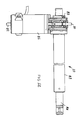
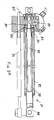
worm screw 83 engages with saidhelical gear wheel 84 which in turn is connected to ascroll 86 and ascrew 87 controlling the inward and outward displacements of therod 88, the extending and withdrawing movements thereof will cause thecurtain box 1 to be raised and lowered respectively. - The screw (of a roller-ball-trapezoidal-triangular and so on type) 87 controlling the withdrawing movement of the
rod 88 is encompassed by aguide tube 89, havingbearings 90, therealong therod 88 axially slide during its reciprocating rectilinear movement. - From figures 12, 13, 14 and 15, it should be apparent that, adjoining the
actuator 20 for raising thecurtain box 1, to be coupled to asecond actuator 20 through a flexible shaft, aspring 91 is applied, for integrating the urging force, and the provision of which will facilitate the operating stroke of eachactuator 20 during the raising and lowering operations of thecurtain box 1. - Said
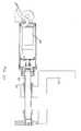
spring 91, which represents an additional urging element, is arranged parallel to theactuator 20 and cooperates with the latter for raising and lowering thecurtain box 1, so as to reduce, the power necessary for performing this operation. - With reference to figure 16, it should be apparent that it is a detail view of a turning over
actuator 10 pivoted between thebottom element 3 andcurtain body 11. - This turning over actuator comprises a
driving motor 92, preferably an electric motor, operating a multi-stage wormscrew reducing unit 97, therefrom anemergency shaft 93 projects. - The latter can be operated from the outside by manual operating tools or an electric tool comprising a drilling tool and battery assembly, to which a tool adapted to engage with the
emergency shaft contour 93 can be applied. - As shown, the multi-stage
worm reducing unit 97 is coupled to a helical screw orworm 94, which rotates and is supported bybearings 100. - This
worm screw 94 drives afurther screw 95 which causes thestem 101 to be axially inwardly and outwardly displaced. - The
rod 101, in particular, is encompassed by aguide tube 96, which holds saidrod 101 properly located so as to provide, as it is operated, a reciprocating rectilinear movement, by entering and exiting from saidguide tube 96. - The screw for withdrawing the rod supports, in turn, a
scroll 99. - From the above disclosure it should be apparent that the invention fully achieves the intended aim and objects.
- In particular, the invention provides a driving device for driving curtains mounted on motor vehicles and the like which, at first, allows to operate the curtain from the outside, even by using manually operated tools and means, in an emergency condition.
- The inventive device, moreover, allows to adjust at will, within comparatively broad ranges, the curtain opening region, thereby it can be easily fitted to all the contingent situations.
- The actuator-spring coupling allows to reduce the control motor power, necessary for controlling the individual movements, thereby providing a great power saving, without requiring the use of an additional power supply battery.
- The invention, as disclosed, is susceptible to several modifications and variations all of which will come within the scope of the inventive idea.
- Moreover, all the constructional details can be replaced by other technically equivalent elements.
- The curtain driving means, in particular, can be selected from different types of driving means, i.e. they can comprise electric, hydraulic or pneumatic motors.
- In practicing the invention, the used materials, as well as the contingent size and shapes, can be any, depending on requirements.
Claims (28)
- A driving device for driving curtains mounted on motor vehicles and the like, comprising a curtain holding box associated with means for turning over said curtain box and housing therein means for opening a cover of said box, and means for extending said curtain, characterized in that said device comprises moreover adjusting means for adjusting the opening and closing of said curtain, and driving elements for driving said adjusting means, through one or more outer control devices.
- A device according to the preceding claim, characterized in that said device comprises a curtain holding box (1), coupled to a motor vehicle (2), said curtain box (1) having a bottom element or frame (3), to which is pivoted a box cover (4) allowing to house, inside said curtain box (1), means for turning over said box, comprising one or more turning over actuators (20), pivoted between said bottom element (3) and curtain body (11) which, in turn, is pivoted on the frame (3) to be applied to the motor vehicle.
- A device according to one or more of the preceding claims, characterized in that said device further comprises actuators (20) arranged at opposite side end portions of said curtain box (1) and applied to said curtain box.
- A device according to one or more of the preceding claims, characterized in that said actuators (20) are mutually coupled by a flexible shaft (20') allowing to simultaneously drive the curtain box cover (4) and curtain body (11), even in the case in which one of said actuators (20) does not operate or is defective.
- A device according to one or more of the preceding claims, characterized in that said two actuators (20) can be replaced by a single central motor, coupled to the raising actuators (20) by one or more transmission shafts (20').
- A device according to one or more of the preceding claims, characterized in that said device comprises moreover, on said curtain body (11), at the two end portions thereof, bearing constructions (30) for supporting fan arms (31) for coupling with said curtain (32).
- A device according to one or more of the preceding claims, characterized in that said fan arms (31) are coupled to a curtain shaft (33), to which is coupled a gear wheel (34) therewith curtain extending means cooperate.
- A device according to one or more of the preceding claims, characterized in that said curtain extending means comprise a rack (35) driven by an actuator (36) allowing to translate said rack (35) and accordingly to perform the opening and closing of said curtain.
- A device according to one or more of the preceding claims, characterized in that said actuator (36) and curtain box (1) turning over means, for opening and closing said cover (4), comprise a motor (40) which is provided with coupling elements (70), for connection with an outer control device, including a hand-held drilling device (51) provided with a built-in storage accumulator.
- A device according to one or more of the preceding claims, characterized in that said outer control device comprises a crank or other manual operating tool.
- A device according to one or more of the preceding claims, characterized in that said coupling elements are coupled by a flexible element (70) and a fitting (71) to an end piece (50) of said motor (40) which, in a case of an operating failure, can be driven so as to turn a screw (55) engaging with a scroll (56) coupled to a rod (57) including a tubular element projecting from a cylinder (36).
- A device according to one or more of the preceding claims, characterized in that, to adjust the extending movement of said curtain (11), are provided adjusting means for adjusting the curtain opening, said adjusting means comprising an adjusting motor (60) operating on a threaded bar (61), therewith is engaged a scroll (62) coupled to the curtain supporting construction (30) or frame, to adjust the positioning of said curtain.
- A device according to one or more of the preceding claims, characterized in that said device further comprises, at one end portion of said threaded bar (61), a clutch element (65) for a recessed head wrench or the like to be coupled to a hand held drilling device (51) or any other outer element, even of a manual type, to operate said curtain bearing frame (30) and for sidewise displacing said curtain, by engagement with said scroll (62).
- A device according to one or more of the preceding claims, characterized in that the connection between said hand-held drilling device (51) and driving motors for driving the elements controlling the curtain opening and closing, are performed by tubes, shafts or flexible fittings.
- A device according to one or more of the preceding claims, characterized in that said. device further comprises a left actuator (20) for raising the curtain box (1) which is coupled, through a flexible shaft to a further right actuator (20).
- A device according to one or more of the preceding claims, characterized in that said device further comprises a further actuator (20) including a shaft (80) for operating in an emergency condition and including a worm screw (83) engaging with a helicoidal gear wheel (84) supported by bearings (85).
- A device according to one or more of the preceding claims, characterized in that said actuator (20) is driven by an electric or oleodynamic or pneumatic motor and is provided at one end of a flexible shaft coupling the two actuators, respectively the right and left actuators.
- A device according to one or more of the preceding claims, characterized in that each said actuator (20) comprises a worm screw (83) engaging with a helicoidal gear wheel (84) which is coupled to a scroll (86) driving said rod (88) for performing inward and outward movements, thereby respectively raising and lowering said curtain box (1).
- A device according to one or more. of the preceding claims, characterized in that said screw (80), driving said rod (88) for performing its withdrawing movement, is encompassed by a guide tube (89) having bearings (84) therealong axially slides said rod (88) to provide a reciprocating rectilinear movement.
- A device according to one or more of the preceding claims, characterized in that each said actuator (20) is coupled to a second actuator (20) through a flexible shaft and comprises an additional urging spring (91), for integrating the urging force during the operating stroke of each said actuator (20) for raising and lowering said curtain box (1).
- A device according to one or more of the preceding claims, characterized in that said device further comprises further actuators (10) driving the opening and closing movement of said curtain box cover (4).
- A device according to one or more of the preceding claims, characterized in that said device further comprises turning over actuators (10), comprising a driving motor (92) driving a multi-stage screw reducing unit (97) therefrom an emergency shaft (93) projects.
- A device according to one or more of the preceding claims, characterized in that said emergency shaft (93) can be driven from the outside by manual tools or an electric tool comprising a drilling device with a built-in storage battery, to which can be applied a tool for engaging with the contour of the emergency shaft (93).
- A device according to one or more of the preceding claims, characterized in that said multi-stage worm reducing unit (97) is coupled to a helical screw or worm (94) which is rotatively supported by bearings (100).
- A device according to one or more of the preceding claims, characterized in that said worm screw (94) drives a further screw (95) for axially driving said rod (101) for performing its inward and outward directed movements.
- A device according to one or more of the preceding claims, characterized in that said rod (101) is encompassed by a guide tube (96) holding said rod so located as to move by providing a rectilinear reciprocating movement, by entering and exiting from said guide tube.
- A device according to one or more of the preceding claims, characterized in that said rod (101) driving screw (95) supports, in turn, a scroll (99).
- A device according to one or more of the preceding claims, characterized in that said urging spring (21) operating for urging said actuator (10), is arranged parallel to and is coupled to the end portions of said actuator, said additional urging spring cooperating with said actuator (10) for raising and lowering said curtain box (1), to allow to reduce the power necessary for performing this movement.
Applications Claiming Priority (2)
| Application Number | Priority Date | Filing Date | Title |
|---|---|---|---|
| IT2001MI001474A ITMI20011474A1 (en) | 2001-07-10 | 2001-07-10 | DEVICE FOR THE CONTROL OF THE HANDLING OF CURTAINS MOUNTED ON COMMERCIAL VEHICLES |
| ITMI20011474 | 2001-07-10 |
Publications (3)
| Publication Number | Publication Date |
|---|---|
| EP1275546A2 true EP1275546A2 (en) | 2003-01-15 |
| EP1275546A3 EP1275546A3 (en) | 2003-05-21 |
| EP1275546B1 EP1275546B1 (en) | 2004-12-01 |
Family
ID=11448038
Family Applications (1)
| Application Number | Title | Priority Date | Filing Date |
|---|---|---|---|
| EP02015185A Expired - Lifetime EP1275546B1 (en) | 2001-07-10 | 2002-07-08 | Device for driving curtains mounted on motor vehicles and the like |
Country Status (5)
| Country | Link |
|---|---|
| EP (1) | EP1275546B1 (en) |
| AT (1) | ATE283950T1 (en) |
| DE (1) | DE60202101D1 (en) |
| ES (1) | ES2236402T3 (en) |
| IT (1) | ITMI20011474A1 (en) |
Cited By (1)
| Publication number | Priority date | Publication date | Assignee | Title |
|---|---|---|---|---|
| WO2021035287A1 (en) * | 2019-08-23 | 2021-03-04 | Jacka Industries Pty Ltd | Actuator and lift system for a camper trailer |
Family Cites Families (4)
| Publication number | Priority date | Publication date | Assignee | Title |
|---|---|---|---|---|
| DE2839557A1 (en) * | 1978-09-12 | 1980-03-20 | Eugen Seitz | Exterior sun blind for car - is mounted at side of roof to pull out with self-supporting braces over side of car |
| DE3909937C2 (en) * | 1989-03-25 | 1994-05-11 | Man Nutzfahrzeuge Gmbh | Electrically movable awning for a passenger transport vehicle, especially a bus |
| ATE125757T1 (en) * | 1990-04-30 | 1995-08-15 | Ivo Mancini | DEVICE FOR STORING AND EXTENDING AN AWNING, PARTICULARLY FOR A STREET VENDOR'S MOTOR VEHICLE. |
| GB9711019D0 (en) * | 1997-05-29 | 1997-07-23 | Timmins Malcolm E | Temporary canopy |
-
2001
- 2001-07-10 IT IT2001MI001474A patent/ITMI20011474A1/en unknown
-
2002
- 2002-07-08 DE DE60202101T patent/DE60202101D1/en not_active Expired - Lifetime
- 2002-07-08 AT AT02015185T patent/ATE283950T1/en not_active IP Right Cessation
- 2002-07-08 ES ES02015185T patent/ES2236402T3/en not_active Expired - Lifetime
- 2002-07-08 EP EP02015185A patent/EP1275546B1/en not_active Expired - Lifetime
Non-Patent Citations (1)
| Title |
|---|
| None |
Cited By (3)
| Publication number | Priority date | Publication date | Assignee | Title |
|---|---|---|---|---|
| WO2021035287A1 (en) * | 2019-08-23 | 2021-03-04 | Jacka Industries Pty Ltd | Actuator and lift system for a camper trailer |
| US11981246B2 (en) | 2019-08-23 | 2024-05-14 | Jacka Industries Pty Ltd | Actuator and lift system for a camper trailer |
| AU2020337176B2 (en) * | 2019-08-23 | 2025-07-24 | Jacka Industries Pty Ltd | Actuator and lift system for a camper trailer |
Also Published As
| Publication number | Publication date |
|---|---|
| DE60202101D1 (en) | 2005-01-05 |
| ITMI20011474A1 (en) | 2003-01-10 |
| ES2236402T3 (en) | 2005-07-16 |
| ITMI20011474A0 (en) | 2001-07-10 |
| ATE283950T1 (en) | 2004-12-15 |
| EP1275546B1 (en) | 2004-12-01 |
| EP1275546A3 (en) | 2003-05-21 |
Similar Documents
| Publication | Publication Date | Title |
|---|---|---|
| US7234757B2 (en) | Electromechanical strut | |
| US7566092B2 (en) | Electromechanical strut | |
| US4852935A (en) | Retractable backlight | |
| US7866729B2 (en) | Powered actuating device for a closure panel of a vehicle | |
| US6951363B2 (en) | Power tonneau cover actuator | |
| CN201891225U (en) | Adjustable sunshade and rainproof awning | |
| US11857048B2 (en) | Mechanism for opening/closing an opening leaf with respect to a frame | |
| KR101048471B1 (en) | Indoor space variable mechanism for motorhome | |
| US20220178488A1 (en) | Pipe inspection device with variable height control | |
| GB2369392A (en) | Vertical blind with a single operating means effecting both rotational and lateral movement of the louvres | |
| EP1275546B1 (en) | Device for driving curtains mounted on motor vehicles and the like | |
| CN107971518A (en) | A kind of production line for plate Drilling operation | |
| TWM458366U (en) | Drive means and seat cushion pillar drive mechanism | |
| EP1826047A2 (en) | Electromechanical strut | |
| US10385603B2 (en) | Window lift mechanism | |
| EP1602297B1 (en) | Telescopic parasol stand | |
| CN202140006U (en) | Driving device for controlling adjusting device in power-operated way | |
| JP3302454B2 (en) | Vehicle roof elevating device | |
| EP1943405B1 (en) | Door system and vehicle provided with such a door system | |
| CN222823080U (en) | A track guide device for vehicle side swing door | |
| CN220463723U (en) | Assembly fixture for continuous casting fan-shaped Duan Lagan nut and hydraulic stretcher | |
| GB2410473A (en) | A cover sheet for a load compartment | |
| EP4306346A1 (en) | Cover assembly for truck bed | |
| AU2023308027B2 (en) | Cover assembly for truck bed | |
| CN211918503U (en) | Car as a house elevating system and car as a house |
Legal Events
| Date | Code | Title | Description |
|---|---|---|---|
| PUAI | Public reference made under article 153(3) epc to a published international application that has entered the european phase |
Free format text: ORIGINAL CODE: 0009012 |
|
| AK | Designated contracting states |
Kind code of ref document: A2 Designated state(s): AT BE BG CH CY CZ DE DK EE ES FI FR GB GR IE IT LI LU MC NL PT SE SK TR |
|
| AX | Request for extension of the european patent |
Free format text: AL;LT;LV;MK;RO;SI |
|
| PUAL | Search report despatched |
Free format text: ORIGINAL CODE: 0009013 |
|
| AK | Designated contracting states |
Designated state(s): AT BE BG CH CY CZ DE DK EE ES FI FR GB GR IE IT LI LU MC NL PT SE SK TR |
|
| AX | Request for extension of the european patent |
Extension state: AL LT LV MK RO SI |
|
| RIC1 | Information provided on ipc code assigned before grant |
Ipc: 7B 60J 11/00 B Ipc: 7B 60P 3/34 B Ipc: 7E 04H 15/06 A |
|
| 17P | Request for examination filed |
Effective date: 20030618 |
|
| 17Q | First examination report despatched |
Effective date: 20030812 |
|
| AKX | Designation fees paid |
Designated state(s): AT BE BG CH CY CZ DE DK EE ES FI FR GB GR IE IT LI LU MC NL PT SE SK TR |
|
| GRAP | Despatch of communication of intention to grant a patent |
Free format text: ORIGINAL CODE: EPIDOSNIGR1 |
|
| GRAS | Grant fee paid |
Free format text: ORIGINAL CODE: EPIDOSNIGR3 |
|
| GRAA | (expected) grant |
Free format text: ORIGINAL CODE: 0009210 |
|
| AK | Designated contracting states |
Kind code of ref document: B1 Designated state(s): AT BE BG CH CY CZ DE DK EE ES FI FR GB GR IE IT LI LU MC NL PT SE SK TR |
|
| PG25 | Lapsed in a contracting state [announced via postgrant information from national office to epo] |
Ref country code: TR Free format text: LAPSE BECAUSE OF FAILURE TO SUBMIT A TRANSLATION OF THE DESCRIPTION OR TO PAY THE FEE WITHIN THE PRESCRIBED TIME-LIMIT Effective date: 20041201 Ref country code: SK Free format text: LAPSE BECAUSE OF FAILURE TO SUBMIT A TRANSLATION OF THE DESCRIPTION OR TO PAY THE FEE WITHIN THE PRESCRIBED TIME-LIMIT Effective date: 20041201 Ref country code: NL Free format text: LAPSE BECAUSE OF FAILURE TO SUBMIT A TRANSLATION OF THE DESCRIPTION OR TO PAY THE FEE WITHIN THE PRESCRIBED TIME-LIMIT Effective date: 20041201 Ref country code: LI Free format text: LAPSE BECAUSE OF FAILURE TO SUBMIT A TRANSLATION OF THE DESCRIPTION OR TO PAY THE FEE WITHIN THE PRESCRIBED TIME-LIMIT Effective date: 20041201 Ref country code: FI Free format text: LAPSE BECAUSE OF FAILURE TO SUBMIT A TRANSLATION OF THE DESCRIPTION OR TO PAY THE FEE WITHIN THE PRESCRIBED TIME-LIMIT Effective date: 20041201 Ref country code: EE Free format text: LAPSE BECAUSE OF FAILURE TO SUBMIT A TRANSLATION OF THE DESCRIPTION OR TO PAY THE FEE WITHIN THE PRESCRIBED TIME-LIMIT Effective date: 20041201 Ref country code: CZ Free format text: LAPSE BECAUSE OF FAILURE TO SUBMIT A TRANSLATION OF THE DESCRIPTION OR TO PAY THE FEE WITHIN THE PRESCRIBED TIME-LIMIT Effective date: 20041201 Ref country code: CH Free format text: LAPSE BECAUSE OF FAILURE TO SUBMIT A TRANSLATION OF THE DESCRIPTION OR TO PAY THE FEE WITHIN THE PRESCRIBED TIME-LIMIT Effective date: 20041201 Ref country code: BG Free format text: LAPSE BECAUSE OF FAILURE TO SUBMIT A TRANSLATION OF THE DESCRIPTION OR TO PAY THE FEE WITHIN THE PRESCRIBED TIME-LIMIT Effective date: 20041201 Ref country code: BE Free format text: LAPSE BECAUSE OF FAILURE TO SUBMIT A TRANSLATION OF THE DESCRIPTION OR TO PAY THE FEE WITHIN THE PRESCRIBED TIME-LIMIT Effective date: 20041201 Ref country code: AT Free format text: LAPSE BECAUSE OF FAILURE TO SUBMIT A TRANSLATION OF THE DESCRIPTION OR TO PAY THE FEE WITHIN THE PRESCRIBED TIME-LIMIT Effective date: 20041201 |
|
| REG | Reference to a national code |
Ref country code: GB Ref legal event code: FG4D |
|
| REG | Reference to a national code |
Ref country code: CH Ref legal event code: EP |
|
| REG | Reference to a national code |
Ref country code: IE Ref legal event code: FG4D |
|
| REF | Corresponds to: |
Ref document number: 60202101 Country of ref document: DE Date of ref document: 20050105 Kind code of ref document: P |
|
| PG25 | Lapsed in a contracting state [announced via postgrant information from national office to epo] |
Ref country code: SE Free format text: LAPSE BECAUSE OF FAILURE TO SUBMIT A TRANSLATION OF THE DESCRIPTION OR TO PAY THE FEE WITHIN THE PRESCRIBED TIME-LIMIT Effective date: 20050301 Ref country code: GR Free format text: LAPSE BECAUSE OF FAILURE TO SUBMIT A TRANSLATION OF THE DESCRIPTION OR TO PAY THE FEE WITHIN THE PRESCRIBED TIME-LIMIT Effective date: 20050301 Ref country code: DK Free format text: LAPSE BECAUSE OF FAILURE TO SUBMIT A TRANSLATION OF THE DESCRIPTION OR TO PAY THE FEE WITHIN THE PRESCRIBED TIME-LIMIT Effective date: 20050301 |
|
| PG25 | Lapsed in a contracting state [announced via postgrant information from national office to epo] |
Ref country code: DE Free format text: LAPSE BECAUSE OF FAILURE TO SUBMIT A TRANSLATION OF THE DESCRIPTION OR TO PAY THE FEE WITHIN THE PRESCRIBED TIME-LIMIT Effective date: 20050302 |
|
| NLV1 | Nl: lapsed or annulled due to failure to fulfill the requirements of art. 29p and 29m of the patents act | ||
| REG | Reference to a national code |
Ref country code: CH Ref legal event code: PL |
|
| PG25 | Lapsed in a contracting state [announced via postgrant information from national office to epo] |
Ref country code: LU Free format text: LAPSE BECAUSE OF NON-PAYMENT OF DUE FEES Effective date: 20050708 Ref country code: IE Free format text: LAPSE BECAUSE OF NON-PAYMENT OF DUE FEES Effective date: 20050708 Ref country code: CY Free format text: LAPSE BECAUSE OF FAILURE TO SUBMIT A TRANSLATION OF THE DESCRIPTION OR TO PAY THE FEE WITHIN THE PRESCRIBED TIME-LIMIT Effective date: 20050708 |
|
| REG | Reference to a national code |
Ref country code: ES Ref legal event code: FG2A Ref document number: 2236402 Country of ref document: ES Kind code of ref document: T3 |
|
| PG25 | Lapsed in a contracting state [announced via postgrant information from national office to epo] |
Ref country code: MC Free format text: LAPSE BECAUSE OF NON-PAYMENT OF DUE FEES Effective date: 20050731 |
|
| PLBE | No opposition filed within time limit |
Free format text: ORIGINAL CODE: 0009261 |
|
| STAA | Information on the status of an ep patent application or granted ep patent |
Free format text: STATUS: NO OPPOSITION FILED WITHIN TIME LIMIT |
|
| 26N | No opposition filed |
Effective date: 20050902 |
|
| ET | Fr: translation filed | ||
| REG | Reference to a national code |
Ref country code: IE Ref legal event code: MM4A |
|
| PGFP | Annual fee paid to national office [announced via postgrant information from national office to epo] |
Ref country code: FR Payment date: 20060706 Year of fee payment: 5 |
|
| PG25 | Lapsed in a contracting state [announced via postgrant information from national office to epo] |
Ref country code: GB Free format text: LAPSE BECAUSE OF NON-PAYMENT OF DUE FEES Effective date: 20060708 |
|
| PGFP | Annual fee paid to national office [announced via postgrant information from national office to epo] |
Ref country code: IT Payment date: 20060731 Year of fee payment: 5 Ref country code: ES Payment date: 20060731 Year of fee payment: 5 |
|
| GBPC | Gb: european patent ceased through non-payment of renewal fee |
Effective date: 20060708 |
|
| PG25 | Lapsed in a contracting state [announced via postgrant information from national office to epo] |
Ref country code: PT Free format text: LAPSE BECAUSE OF NON-PAYMENT OF DUE FEES Effective date: 20050501 |
|
| REG | Reference to a national code |
Ref country code: FR Ref legal event code: ST Effective date: 20080331 |
|
| PG25 | Lapsed in a contracting state [announced via postgrant information from national office to epo] |
Ref country code: FR Free format text: LAPSE BECAUSE OF NON-PAYMENT OF DUE FEES Effective date: 20070731 |
|
| REG | Reference to a national code |
Ref country code: ES Ref legal event code: FD2A Effective date: 20070709 |
|
| PG25 | Lapsed in a contracting state [announced via postgrant information from national office to epo] |
Ref country code: ES Free format text: LAPSE BECAUSE OF NON-PAYMENT OF DUE FEES Effective date: 20070709 |
|
| PG25 | Lapsed in a contracting state [announced via postgrant information from national office to epo] |
Ref country code: IT Free format text: LAPSE BECAUSE OF NON-PAYMENT OF DUE FEES Effective date: 20070708 |