EP1275363A2 - Elevation chair - Google Patents
Elevation chair Download PDFInfo
- Publication number
- EP1275363A2 EP1275363A2 EP02014944A EP02014944A EP1275363A2 EP 1275363 A2 EP1275363 A2 EP 1275363A2 EP 02014944 A EP02014944 A EP 02014944A EP 02014944 A EP02014944 A EP 02014944A EP 1275363 A2 EP1275363 A2 EP 1275363A2
- Authority
- EP
- European Patent Office
- Prior art keywords
- seat
- main body
- elevation
- chair
- wheel
- Prior art date
- Legal status (The legal status is an assumption and is not a legal conclusion. Google has not performed a legal analysis and makes no representation as to the accuracy of the status listed.)
- Granted
Links
Images








Classifications
-
- A—HUMAN NECESSITIES
- A61—MEDICAL OR VETERINARY SCIENCE; HYGIENE
- A61G—TRANSPORT, PERSONAL CONVEYANCES, OR ACCOMMODATION SPECIALLY ADAPTED FOR PATIENTS OR DISABLED PERSONS; OPERATING TABLES OR CHAIRS; CHAIRS FOR DENTISTRY; FUNERAL DEVICES
- A61G7/00—Beds specially adapted for nursing; Devices for lifting patients or disabled persons
- A61G7/10—Devices for lifting patients or disabled persons, e.g. special adaptations of hoists thereto
- A61G7/1013—Lifting of patients by
- A61G7/1019—Vertical extending columns or mechanisms
-
- A—HUMAN NECESSITIES
- A61—MEDICAL OR VETERINARY SCIENCE; HYGIENE
- A61G—TRANSPORT, PERSONAL CONVEYANCES, OR ACCOMMODATION SPECIALLY ADAPTED FOR PATIENTS OR DISABLED PERSONS; OPERATING TABLES OR CHAIRS; CHAIRS FOR DENTISTRY; FUNERAL DEVICES
- A61G5/00—Chairs or personal conveyances specially adapted for patients or disabled persons, e.g. wheelchairs
- A61G5/10—Parts, details or accessories
- A61G5/12—Rests specially adapted therefor, e.g. for the head or the feet
- A61G5/125—Rests specially adapted therefor, e.g. for the head or the feet for arms
-
- A—HUMAN NECESSITIES
- A61—MEDICAL OR VETERINARY SCIENCE; HYGIENE
- A61G—TRANSPORT, PERSONAL CONVEYANCES, OR ACCOMMODATION SPECIALLY ADAPTED FOR PATIENTS OR DISABLED PERSONS; OPERATING TABLES OR CHAIRS; CHAIRS FOR DENTISTRY; FUNERAL DEVICES
- A61G5/00—Chairs or personal conveyances specially adapted for patients or disabled persons, e.g. wheelchairs
- A61G5/10—Parts, details or accessories
- A61G5/14—Standing-up or sitting-down aids
-
- A—HUMAN NECESSITIES
- A61—MEDICAL OR VETERINARY SCIENCE; HYGIENE
- A61G—TRANSPORT, PERSONAL CONVEYANCES, OR ACCOMMODATION SPECIALLY ADAPTED FOR PATIENTS OR DISABLED PERSONS; OPERATING TABLES OR CHAIRS; CHAIRS FOR DENTISTRY; FUNERAL DEVICES
- A61G7/00—Beds specially adapted for nursing; Devices for lifting patients or disabled persons
- A61G7/10—Devices for lifting patients or disabled persons, e.g. special adaptations of hoists thereto
- A61G7/104—Devices carried or supported by
- A61G7/1046—Mobile bases, e.g. having wheels
-
- A—HUMAN NECESSITIES
- A61—MEDICAL OR VETERINARY SCIENCE; HYGIENE
- A61G—TRANSPORT, PERSONAL CONVEYANCES, OR ACCOMMODATION SPECIALLY ADAPTED FOR PATIENTS OR DISABLED PERSONS; OPERATING TABLES OR CHAIRS; CHAIRS FOR DENTISTRY; FUNERAL DEVICES
- A61G7/00—Beds specially adapted for nursing; Devices for lifting patients or disabled persons
- A61G7/10—Devices for lifting patients or disabled persons, e.g. special adaptations of hoists thereto
- A61G7/1063—Safety means
-
- A—HUMAN NECESSITIES
- A61—MEDICAL OR VETERINARY SCIENCE; HYGIENE
- A61G—TRANSPORT, PERSONAL CONVEYANCES, OR ACCOMMODATION SPECIALLY ADAPTED FOR PATIENTS OR DISABLED PERSONS; OPERATING TABLES OR CHAIRS; CHAIRS FOR DENTISTRY; FUNERAL DEVICES
- A61G7/00—Beds specially adapted for nursing; Devices for lifting patients or disabled persons
- A61G7/10—Devices for lifting patients or disabled persons, e.g. special adaptations of hoists thereto
- A61G7/1073—Parts, details or accessories
- A61G7/1074—Devices foldable for storage
-
- A—HUMAN NECESSITIES
- A61—MEDICAL OR VETERINARY SCIENCE; HYGIENE
- A61G—TRANSPORT, PERSONAL CONVEYANCES, OR ACCOMMODATION SPECIALLY ADAPTED FOR PATIENTS OR DISABLED PERSONS; OPERATING TABLES OR CHAIRS; CHAIRS FOR DENTISTRY; FUNERAL DEVICES
- A61G7/00—Beds specially adapted for nursing; Devices for lifting patients or disabled persons
- A61G7/10—Devices for lifting patients or disabled persons, e.g. special adaptations of hoists thereto
- A61G7/1073—Parts, details or accessories
- A61G7/1082—Rests specially adapted for
- A61G7/1088—Back
-
- A—HUMAN NECESSITIES
- A61—MEDICAL OR VETERINARY SCIENCE; HYGIENE
- A61G—TRANSPORT, PERSONAL CONVEYANCES, OR ACCOMMODATION SPECIALLY ADAPTED FOR PATIENTS OR DISABLED PERSONS; OPERATING TABLES OR CHAIRS; CHAIRS FOR DENTISTRY; FUNERAL DEVICES
- A61G7/00—Beds specially adapted for nursing; Devices for lifting patients or disabled persons
- A61G7/10—Devices for lifting patients or disabled persons, e.g. special adaptations of hoists thereto
- A61G7/1073—Parts, details or accessories
- A61G7/1082—Rests specially adapted for
- A61G7/1094—Hand or wrist
-
- A—HUMAN NECESSITIES
- A61—MEDICAL OR VETERINARY SCIENCE; HYGIENE
- A61G—TRANSPORT, PERSONAL CONVEYANCES, OR ACCOMMODATION SPECIALLY ADAPTED FOR PATIENTS OR DISABLED PERSONS; OPERATING TABLES OR CHAIRS; CHAIRS FOR DENTISTRY; FUNERAL DEVICES
- A61G7/00—Beds specially adapted for nursing; Devices for lifting patients or disabled persons
- A61G7/10—Devices for lifting patients or disabled persons, e.g. special adaptations of hoists thereto
- A61G7/1073—Parts, details or accessories
- A61G7/1082—Rests specially adapted for
- A61G7/1098—Ankle or foot
-
- A—HUMAN NECESSITIES
- A61—MEDICAL OR VETERINARY SCIENCE; HYGIENE
- A61G—TRANSPORT, PERSONAL CONVEYANCES, OR ACCOMMODATION SPECIALLY ADAPTED FOR PATIENTS OR DISABLED PERSONS; OPERATING TABLES OR CHAIRS; CHAIRS FOR DENTISTRY; FUNERAL DEVICES
- A61G2200/00—Information related to the kind of patient or his position
- A61G2200/30—Specific positions of the patient
- A61G2200/36—Specific positions of the patient standing
-
- Y—GENERAL TAGGING OF NEW TECHNOLOGICAL DEVELOPMENTS; GENERAL TAGGING OF CROSS-SECTIONAL TECHNOLOGIES SPANNING OVER SEVERAL SECTIONS OF THE IPC; TECHNICAL SUBJECTS COVERED BY FORMER USPC CROSS-REFERENCE ART COLLECTIONS [XRACs] AND DIGESTS
- Y10—TECHNICAL SUBJECTS COVERED BY FORMER USPC
- Y10S—TECHNICAL SUBJECTS COVERED BY FORMER USPC CROSS-REFERENCE ART COLLECTIONS [XRACs] AND DIGESTS
- Y10S297/00—Chairs and seats
- Y10S297/10—Occupant-arising assist
Definitions
- This invention relates to an elevation chair.
- elevation chair including features of claim 1, 6, or 12. Furthermore detailed embodiments are described in the dependent claims 2, 3, 4, 5, 7, 8, 9, 10, 11, 13, 14, 15, and 16.
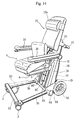
- FIG. 1 shows an embodiment of an elevation chair (a chair with a seat which is lifted up and down) of the present invention.
- This elevation chair running on the floor, etc., has a seat 4 which is inclined and elevated (lifted).
- a lower part of the elevation chair has a pair of bar-shaped leg portions 36, a wheel 2 is attached to both (front and rear) end portions of each of the leg portions 36, and the leg portions 36 are connected with a base member 37.
- a post 38 is fixed to the base member 37 as to incline backward, and a driving mechanism M, to elevate (ascend and descend) the seat 4 and a back portion 10, is detachably attached to the post 38.
- a battery 15 is placed on the post 38 to elevate and incline the seat 4 of the elevation chair independently with electricity. And, a handle 25 for movement is disposed on an upper rear side of the post 38 as the elevation chair can easily run (move).
- the seat 4 is provided with a seat frame 5 and a seat main body 7 attached to a forth end portion 6 of the seat frame 5 as to incline forward, and, keeping a horizontal state, elevated (lifted up and down) by the driving mechanism M. And the seat main body 7 is inclined forward by an oscillation mechanism N.
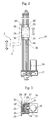
- the driving mechanism M to elevate (lift) the seat 4 is, as shown in Figure 2, provided with a motor 16, a reducer portion 17, a guide rail portion 18, a rotating male screw portion 26, a sliding female screw portion 27, and a sliding member 28 which are united into one unit.
- Figure 3 is a cross-sectional top view of the driving mechanism M in which rotation (torque) of the motor 16 is transmitted to the rotating male screw portion 26 through the reducer portion 17 to revolve.
- the sliding female screw portion 27 screwed to the rotating male screw portion 26 has a pair of first rollers 29 which fit to guide rails 18 ' parallel to the rotating male screw portion 26, and moved (screwed) up and down by the rotation of the rotating male screw portion 26. That is to say, the sliding female screw portion 27 elevates (screws) the rotating male screw portion 26 up and down by restriction of the rotating male screw portion 26 by the guide rails 18 ' .
- the sliding female screw portion 27 is connected to the sliding member 28 through a connencting shaft 19 (refer to Figure 3), and the sliding member 28 is connected to the seat frame 5 of the seat 4 (refer to Figure 2). Therefore, the seat 4 (the seat frame 5) is elevated by elevation of the sliding female screw portion 27. And, the seat frame 5 is set to be guided by inner faces of the post 38 shown in Figure 1.
- second rollers 30, having rotational axes at right angles with rotational axes of the first rollers 29, are attached to the sliding member 28 as to rotate and disposed as to hold a guide rail 18" parallel to the rotating male screw portion 26.
- the guide rail portion 18 is composed of the guide rails 18' and the guide rail 18 " , which are constructed as that the first rollers 29 prevent deviation (sheering and trembling) of the sliding member 28 (the seat 4) in back-and-forth direction and the second rollers 30 prevent the deviation in left-and-right direction.
- the seat frame 5 is a L-shaped supporting frame having a horizontal portion supporting the seat main body 7 horizontal and a vertical portion holding the back portion 10, and an armrest 20, laid horizontal and raised vertical, is attached to each of left and right sides of the vertical portion as to be oscillatable. And, a headrest 10a, detachable and position-changeable to correspond to the head height of the user, is disposed on an upper part of the back portion 10.
- the driving mechanism M is disposed on an upper and a lower side of the post 38 respectively, the sliding member 28 as a component of the driving mechanism M is attached to the vertical portion of the seat frame 5 of the seat 4, and the seat 4 is elevated stably with the seat frame 5 guided by grooves on the post 38.
- the elevation chair has an oscillation mechanism N to elevate the seat 4 horizontally and automatically incline the seat main body 7 forward at a predetermined height.
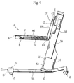
- Figure 4 shows the elevation and inclination of the seat 4.
- the oscillation mechanism N is provided with a tension spring 44, a running pulley 46, a flexible member 39, a first pulley 40, and a second pulley 41.
- a tension spring 44 a running pulley 46
- a flexible member 39 a flexible member 39
- a first pulley 40 a first pulley 40
- a second pulley 41 a second pulley 41.
- an end of the flexible member 39 is attached to a supporting portion 42 on a rear end of the seat main body 7, and another end is attached to an attachment member 43 through the running pulley 46, the first pulley 40, and the second pulley 41.
- the attachment member 43 is hitched to a hitching member 53 of a fixation portion 45 fixed to the base member 37.
- a long hole is formed on a side face of the seat main body 7, and the running pulley 46, guided and supported by the long hole as to be movable, is connected to an end of the tension spring 44 disposed in front of the seat main body 7.
- the tension spring 44 is set to be always pushing the running pulley 46 forward, giving tension to the flexible member 39, and stored in the seat main body 7 without laxation.
- the seat main body 7 When the seat 4 is ascended further, the rear end of the seat main body 7 is raised along the ascension through the running pulley 46, the seat main body 7 is oscillated around an axis G to gradually incline forward, and the seat main body 7 is in a forward-inclined position with a predetermined inclination angle ⁇ as shown with a mark A 3 when the seat 4 reaches a predetermined height.
- the height, at which the seat main body 7 begins the inclination can be changed by hitching the attachment portion 43 on the end portion of the flexible member 39 to another hitching portion 53 ' on the fixation portion 45 fixed to the base member 37. That is to say, the attachment member 43 as a component of the oscillation mechanism N has an adjustment mechanism F to change the forward-inclination starting height. And, although not shown in Figures, the number of the hitching members 53 and 53' may be 3 or more, and plural hitching holes may be formed on the flexible member 39 to be hitched onto a hitching piece on the fixation portion 45. With the adjustment mechanism F, the height at which the seat main body 7 begins the inclination is changed in plural stages.
- the attachment member 43 on the end portion of the flexible member 39 may not be hitched to the fixation portion 45 fixed to the base member 37, namely, may be freely ascended and descended to interrupt the automatic inclination of the seat main body 7 at the predetermined height, and the seat 4 can be elevated with horizontal state. That is to say, the attachment member 43 as a component of the oscillation mechanism N has a non-inclination switching mechanism E to interrupt the automatic forward inclination of the seat main body 7 and elevate the seat 4 with horizontal state.
- the seat 4 has an angle detecting means L to stop the driving mechanism M when the seat main body 7 reaches the predetermined inclination angle ⁇ .
- the angle detecting means L is provided with a shielding plate 8 and a photosensor 9 attached to the seat frame 5 to detect the inclination angle ⁇ through an inclination angle of the shielding plate 8 which inclines along with the seat main body 7.
- the photosensor 9 attached to the seat frame 5 is blocked by the shielding plate 8 attached to the seat main body 7. That is to say, as shown in a cross-sectional view of the angle detecting means L in Figure 8, the shielding plate 8 is placed between an emission portion 9a and a receiving portion 9b disposed on a U-shaped main body 9c, and the driving mechanism M works when the photosensor 9 is switched off.
- the inclination angle ⁇ of the seat main body 7 can be changed by changing the attached angle of the photosensor 9.
- the inclination angle ⁇ which is preferably 15° to 35 ° , is most preferably 25 ° .
- the angle detecting means L may be composed of a micro switch and a contact piece which contacts and parts from a terminal of the micro switch.
- Figure 9 through Figure 12 show an automatic braking mechanism B mounted on the elevation chair.
- the wheels 2 are disposed front and rear portions on the elevation chair, and the automatic braking mechanism B is disposed on a position of each of the wheels 2 on the front portion (as shown in Figure 1).
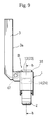
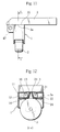
- the wheel 2 is released when a footrest 3 attached to the wheel bracket 1 of the wheel 2 is laid horizontal (as in Figures 11 and 12), and the wheel 2 is braked when the footrest 3 is raised upright (as in Figures 9 and 10).
- the automatic braking mechanism B has the footrest 3 of flat plate attached to the wheel bracket 1 as to held vertical by an elastic member 47. And, a front supporting shaft 11 is disposed on a front upper position of an axle 48 as to be parallel to the axle 48 and a rear supporting shaft 21 is disposed on a rear upper position of the axle 48 as to be parallel to the axle 48, and a front braking arm 12 having L-shaped cross section is attached to the front supporting shaft 11 as to oscillate and a rear braking arm 22 having L-shaped cross section is attached to the rear supporting shaft 21 as to oscillate.
- a receiving portion 13 on an end of the front braking arm 12 and a receiving portion 23 on an end of the rear braking arm 22 are protruding from an opening on a top plate 35 of the wheel bracket 1, and a brake pad 14 attached on another end of the front braking arm 12 and a brake pad 24 attached on another end of the rear braking arm 22 are respectively pressed to front and rear parts of the wheel 2 by self weight of the front and rear braking arms 12 and 22, and the brake pads 14 and 24. That is to say, the brake pads 14 and 24 are pressed to the wheel 2 to brake the wheel 2 in the vertical upright state of the footrest 3.
- widths of the brake pads 14 and 24 are larger than the width of the wheel 2 to slide on the whole width of the wheel 2 to enhance the braking ability by enlarging the sliding portion.
- the automatic braking ability with the front and rear braking arms 12 and 22 is determined by positions of tangent points 14a and 24a of the brake pads 14 and 24 with the wheel 2 as shown in Figure 10. That is to say, the tangent point 14a is an intersectional point of a radius R of the wheel 2 and an oscillation radius r 1 of the front braking arm 12, and a distance C, between the front supporting shaft 11 of the front braking arm 12 and the axle 48, is set to be smaller than a sum of the radius R of the wheel 2 and the oscillation radius r 1 of the front braking arm 12. Therefore, when the wheel 2 starts rotation in clockwise direction H in Figure 10, the brake pad 14 presses toward the center of the wheel 2 in the radius R direction to enhance the braking ability by frictional force. This automatic braking function stops the rotation in the clockwise direction H of the wheel 2.
- the front braking arm 12 is free from rotation of the wheel 2 in anti-clockwise direction J.
- the wheel 2 can run while the brake pad 14 is sliding on a rotating face of the wheel 2 (without braking). Therefore, in the automatic braking mechanism B, the rear braking arm 22 is disposed on a position symmetric to the front braking arm 12 with respect to a vertical line going through the axle 48, the rotation of the wheel 2 in the anti-clockwise direction J is prevented by the braking function to prevent the wheel 2 from moving in back-and-forth direction.
- the driving mechanism M for elevating the seat 4 is provided with the motor 16, the reducer portion 17, the guide rail portion 18, the rotating male screw portion 26, the sliding female screw portion 27, and the sliding member 28, and united as a unit.
- the elevation chair of the present invention (the driving mechanism M) is maintained, a cover 49 and an electric portion 50 are removed from the main body of the chair, fixation screws 51 to fix the driving mechanism M to a vertical portion of the seat frame 5 are unscrewed to remove the driving mechanism M as one unit from the post 38. That is to say, the driving mechanism M to be maintained can be removed from the main body of the chair without disassembly into individual parts.
- an upper part of the driving mechanism M is pinned to an upper part of the post 38 with a fixation member 52, and, although not shown in Figures, a lower part has a hook-shaped hitching portion to be hitched to a lower part of the post 38. Therefore, the driving mechanism M can be taken out of the post 38 only with removal of the fixation member 52.
- This elevation chair similar to the elevation chair described with Figure 1, has a seat 4 which is elevated (lifted) and inclined, and runs on floor, etc.
- a lower portion of the elevation chair is provided with a lower fixation portion 64 as a base portion to hold the post 38, having leg portions 36 connected to the front of the lower fixation portion 64 on left and right sides.
- Wheels 2 are attached to forth end portions of the leg portions 36 and wheels 92 are attached to the lower fixation portion 64 on the left and right sides as to rotate.
- the posy 38 is placed on and fixed to the lower fixation portion 64 as to incline backward, and a driving mechanism M, to elevate (ascend and descend) the seat 4 and a back portion 10 (a sliding member 28), is detachably attached to the post 38.
- a battery 15 is mounted on the post 38 to independently conduct elevation and inclination of the seat 4 of the elevation chair electrically.
- a handle 25 for transfer is disposed on a rear side of the post 38 to easily transfer (move) the elevation chair.
- a pedal braking mechanism D is mounted behind the lower fixation portion 64 to brake the wheels 92 and certainly fix the position of the elevation chair.
- the seat 4 is provided with a seat frame 5 and a seat main body 7 attached to a forth end portion 6 of the seat frame 5 as to incline forward.
- the seat 4 keeping horizontal state, is elevated (lifted up and down) by the driving mechanism M, and the seat main body 7 is inclined forward by an oscillation mechanism N at a predetermined height.
- the seat 4 is connected to the sliding member 28 elevated along the post 38 to be elevated.
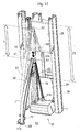
- the driving mechanism M to elevate the seat 4, as shown in Figure 15, is provided with the elevatable sliding member 28 to which the seat 4 is connected, an expansion actuator 61 which expands and contracts up and down, a running rotation pulley 62 disposed on an upper end of the expansion actuator 61, and a flexible member 63.
- the flexible member 63 of which end 63a is attached to a fixation metal 69 of the lower fixation portion 64, is expanded upward and suspended on the running rotation pulley 62, and another end 63b of the flexible member 63 is attached to an attachment metal 68 of the sliding member 28 situated low.
- elevation movement dimension of the running rotation pulley 62 as a component of the driving mechanism M can be diminished.
- Vertical dimension and expansion length of the expansion actuator 61 can be made small, and the device is made compact and light. Therefore, the elevation chair can be light-weight, moved easily, and handled properly.
- the flexible member 63 is composed of a flexible belt 65 having a double-suspension construction in which an outer belt 66 and an inner belt 67 are layered.
- the inner belt 67 is suspended to be tensed as to suspend the sliding member 28 (the seat 4) from the fixation metal 69 (the lower fixation portion 64) through the running rotation pulley 62 as shown in Figure 15, and the outer belt 66 is untensed and suspended on the lower fixation portion 64, the running rotation pulley 62, and the sliding member 28. That is to say, in normal working, only the inner belt 67 suspends the sliding member 28 to elevate with the expansion actuator 61.
- a safety device is constructed as that in emergency in which overload is generated by malfunction of the expansion actuator 61, and the inner belt 67 is broken by aging, as shown in Figure 16, the outer belt 66, suspended in loose state, is tensed to suspend the sliding member 28 and retain the position (prevent falling).
- the sliding member 28 is provided with two rollers 96 on each of upper and lower positions to elevate along the guide rails of the post 38 to smoothly elevate the sliding member 28 without trembling.
- a position-corresponding plate 70 is disposed between the outer belt 66 and the inner belt 67.
- the position-corresponding plate 70 is pushed to press the outer belt 66 in normal working to hold the outer belt 66 as not to be excessively loosened.
- the outer belt 66 is tensed to suspend the sliding member 28 to retain the position and push the position-corresponding plate 70 to the inner belt 67 side to change the position.
- the position-corresponding plate 70 contacts a detecting portion of a displacement detecting mechanism 71 (a limit switch) to stop (by electric shielding) the expansion actuator 61 of the driving mechanism M.
- the expansion actuator 61 does not break the outer belt 66, and the seat 4 is (although slightly descended by idle length of the outer belt 66) suspended and held.
- the outer belt 66 and the inner belt 67 are attached to the attachment metal 68 of the sliding member 28 at different heights.
- a belt is folded at the middle which is an end 63a, and two ends on the opposite side are ends 63b. These two belts are the outer belt 66 and the inner belt 67.
- the end 63b on the outer belt 66 side is attached to an upper pin 68' of the attachment metal, and the inner belt 67 side is attached to a lower pin 68". Therefore, the outer belt 66 is naturally loosened when the inner belt 67 is tensed.
- the flexible belt 65 is easily made thereby without error in assembly. And, the belt does not fall out of the lower fixation portion 64 when the inner or the outer belt is tensed because the folded portion is formed into a loop by sewing.
- the oscillation mechanism N is provided with an elevation pulley 75 attached to the sliding member 28, a middle deflection shaft 76 attached the post 38, and a hook 77 with a deflection shaft hitched to a hitching protruding portion 80.
- the suspension belt 78 raises the seat main body 7 as to incline forward with this pulley mechanism by elevation movement of the elevation pulley 75 of the sliding member 28.
- an end portion 78a is connected to a rear end portion 79 of the seat main body 7 to suspend (composed similar to the embodiment in Figure 1), and another end portion 78b is fixed to a fixation metal 72 on an upper portion of the post 38.
- suspension belt 78 extends upwards from the end portion 78a to be suspended on the elevation pulley 75 and on the middle deflection shaft 76, then, extends downwards to be suspended on the hook 77 with the deflection shaft and connected to the upper fixation metal 72.
- an elevation movement stroke of the sliding member 28 (the elevation pulley 75) to incline the seat main body 7 is required to be only a half of that when the seat main body 7 is directly raised because the elevation pulley 75 elevated by the sliding member 28 works as a running pulley.
- the hook 77 with the deflection shaft can change the height of hitching position, although not shown in Figures, only by hitching a hole on the hook 77 to the hitching protruding portion 80 of the post 38.
- the hook 77 with the deflection shaft is always pulled up by the suspension belt 78 to prevent the hook 77 from falling off the hitching protruding portion 80. So the hook 77 with the deflection shaft is positioned lower than the elevation pulley 75, and the end portion 78b of the belt 78 is fixed to the upper fixation metal 72 to make a loop of the belt.
- the middle deflection shaft 76 is disposed as the suspension belt 78, between the middle deflection shaft 76 and the hook 77 with the deflection shaft, is pulling the hook 77 with the deflection shaft always in a constant direction, and the hook 77 with the deflection shaft receives a component of tensile force.
- the hook 77 with the deflection shaft is prevented from falling out of hitching, and having a simple construction, not receiving strong bending force, which can resist only tensile force in one direction.
- the suspension belt 78 raises the seat main body 7 to be inclined forward with the pulley mechanism.
- an adjustment mechanism F which can change the height at which the inclination of the seat main body 7 begins corresponding to height of the person who sits on the seat 4.
- the adjustment mechanism F composed of hitching protruding portions 80 and 80' disposed on different heights on the front side of the post 38 to which the hook 77 with the deflection shaft is hitched, expands application range of the elevation chair corresponding to the difference of the height.
- the hitching protruding portions 80 and 80' are disposed on the front side of the post 38 on plural stages (two stages) in vertical direction. Then, the length that the end portion 78a of the suspension belt 78 contacts the rear end portion of the long hole 73 on the seat main body 7 to raise the seat main body 7 is changed by changing the hitching height of the hook 77 with the deflection shaft from the protruding portion 80 to the protruding portion 80' (or from the protruding portion 80' to the protruding portion 80) to change the height at which the forward inclination begins.
- the seat main body 7 starts the inclination at an early (a lower) predetermined position for a short person.
- the seat main body 7 later than the case of the protruding portion 80, starts the inclination at a higher position for a tall person.
- the difference of the height, at which the inclination begins, between for the short person and for the tall person is the twice of the difference of height between the protruding portion 80 and the protruding portion 80'.
- the seat 4 can be kept horizontal when elevated without the automatic forward inclination of the seat main body 7 at the predetermined height by changing the hitching height of the hook 77 with the deflection shaft to the position of a hitching protruding portion 80" (the uppermost stage) disposed further (a non-inclination switching mechanism E).
- the end portion 78a of the sliding member 78 does not contact the rear end portion of the long hole 73, and the rear end portion 79 of the seat main body 7 is not raised even if the sliding member 28 ascends to the uppermost portion.
- the expansion actuator 61 itself detects the elevation stroke S, stops its expansion movement, and the inclination of the seat main body 7 is stopped.
- a position detecting mechanism 81 such as a limit switch is disposed on the post 38, a protruding piece 82 on the sliding member 28 contacts the position detecting mechanism 81 when elevated to a predetermined height, and the driving mechanism M (the expansion actuator 61) is stopped by the position detecting mechanism 81.
- a working switch 83 is disposed near (above) the protruding portion 80 on the post 38.
- the hook 77 with the deflection shaft hitches to the protruding portion 80, the hook 77 with the deflection shaft pushes the working switch 83 to electrically switch on the position detecting mechanism 81 (the limit switch) above.
- a two-staged upper limit position detecting means is required.
- a stopping mechanism for the driving mechanism M when the hook 77 with the deflection shaft is hitched to the protruding portion 80 for a short person, the hook 77 with the deflection shaft pushes the working switch 83 to electrically switch on the position detecting mechanism 81 (the limit switch) above, the sliding member 28 is elevated by the driving mechanism M, the protruding piece 82 on the sliding member 28 contacts the position detecting mechanism 81 at the predetermined height to stop the driving mechanism M (the expansion actuator 61).
- the position detecting mechanism 81 (the limit switch) is electrically switched off, the detection is not conducted when the protruding piece 82 contacts the position detecting mechanism 81, the sliding member 28 is elevated further, then, the expansion actuator 61 itself detects the predetermined elevation stroke to stop its expansion movement.
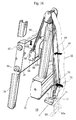
- FIG. 18 A schematic perspective view is shown in Figure 18, and Figures 19 and 20 are side views.
- rotation of the wheel 92 on the rear side is restricted by pressing an end portion 89a of a brake shaft 89 to the wheel 92.
- Figure 18 mainly shows the wheel 92 on the left side, the wheel 92 on the right side has a similar and symmetric construction. That is to say, the brake shaft 89 is a rod-like member bent U-shaped approximately.
- the braking mechanism D is provided with a brake pedal 86 of plate and the rod-like metal brake shaft 89.
- An end portion 86a of the brake pedal 86 is attached to an inner portion of the lower fixation portion 64 on the rear side as to oscillate around a first horizontal axis 87 in lateral direction, and an operation pedal portion 88 is disposed on another end portion 86b (another end side portion) as to protrude outward from the lower fixation portion 64.
- the U-shaped rod-like brake shaft 89 is provided with a leg portion 89 ', namely, a supporting rod in proceeding direction of the chair, and a back portion 89", namely, a horizontal beam in lateral direction.
- a middle portion 90 of the leg portion 89 ' of the brake shaft 89 is attached as to oscillate around a second horizontal axis 91 in lateral direction near the wheel 92 of the lower fixation portion 64, and the end portion 89a of the leg portion 89 ' can contact the wheel 92 with the oscillation movement of the brake shaft 89 around the second horizontal axis 91 to brake the wheel 92.
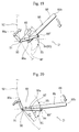
- the back portion 89" of the brake shaft 89 is attached to the lower face side of the brake pedal 86 on a position on the operation pedal portion 88 side toward the position of the first horizontal axis 87, and, as shown in the side view of Figure 19, out of an imaginary line going through the first horizontal axis 87 and the second horizontal axis 91 (above the imaginary line in Figure 19), and oscillatable around a third horizontal axis 94 along with the brake pedal.
- the elastic deformation of the back portion 89 " of the brake shaft 89 works to keep the braked state and the released state. Especially, in the braked state, the wheel 92 is firmly pressed by elastic force with the end portion 89a.
- This position retaining work is caused by elastic work of the brake shaft 89 (the back portion 89" ) made of metal, and, as shown in Figure 19 and Figure 20, difference between an oscillation radius r 11 of the first horizontal axis 87 and the third horizontal axis 94 of the brake pedal 86 and an oscillation radius r 12 of the second horizontal axis 91 and the third horizontal axis 94 of the brake shaft 89, namely, the oscillation radius r 12 is longer than the oscillation radius r 11 .
- the connecting point of the brake shaft 89 and the brake pedal 86 passes an imaginary line going through the first horizontal axis 87 and the second horizontal axis 91, and the brake shaft 89 becomes static on two intersection points 95 of two different arc traces without elastic deformation. That is to say, the connecting point above (of the third horizontal axis 94) between the two intersection points 95 automatically returns to one of the two intersection points 95 with elasticity.
- a footrest 93 of plate is disposed above the forward wheels 2 as to be position-changeable.
- a person sitting on the seat 4 can put the feet on the footrest 93 to prevent the feet from dragging in transfer. And, the position of the footrest 93 is changed parallel to the leg portion 36 not to hinder the person to get on and off the seat 4.
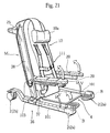
- FIG 21 is a perspective view showing another embodiment of the elevation chair of the present invention.
- This elevation chair similar to the elevation chair described with Figure 1 and Figure 14, runs (moves) on the floor and has a seat 4 elevated (ascended and descended) by the driving mechanism M as described above.
- a lower part of the elevation chair is provided with a base member 37 to hold a post 38, horizontal leg portions 36 are disposed both sides of the base member 37, and wheels 2 are disposed on front positions and rear positions of the leg portions 36 as the elevation chair has 4 wheels.
- the leg portion 36 is composed of a rear fixation portion 103 and a front oscillation arm portion 101 which is before the base member 37.
- the oscillation arm portion 101 is a horizontal supporting member protruding forward, and a front wheel 2a is attached to a forth end of the oscillation arm portion 101. And, the front wheel 2a, with a rear wheel 2b attached to the rear fixation portion 103, supports the elevation chair stably as to run.
- the oscillation arm portion 101 is attached to the fixation portion 103 as to be freely switched between a forward-protruding used state and an upward-folded stored state at a base end portion side of the oscillation arm portion 101.
- Figure 21 is showing the used state, and the oscillation arm portion 101 is folded at the base end portion side in a direction of arrows V to be changed to the stored state.
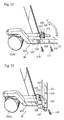
- Figure 22 and Figure 23 are perspective views to explain the leg portion 36.
- Figure 22 shows the used state
- Figure 23 shows the stored state.
- an auxiliary wheel 102 disposed on the base end portion of the oscillation arm portion 101, protrudes downward and contacts the ground in the stored state.
- the base end portion of the oscillation arm portion 101 is attached to the fixation portion 103 as to freely oscillate, and 104 is an oscillation center.
- a fixation piece 105 is fixed to the fixation portion 103 and an oscillation piece 106 is fixed to the base end portion of the oscillation arm portion 101 as to face.
- the fixation piece 105 and the oscillation piece 106 are connected with a first connecting shaft 107 and a second connecting shaft 108.
- the second connecting shaft 108 although fixed to the fixation piece 105, slides along an arc long hole on the oscillation piece 106, and the oscillation arm portion 101 (the oscillation piece 106), of which oscillation angle is restricted to approximately 90° , can oscillate around the first connecting shaft 107 as a center.
- the oscillation arm portion 101 in the used state, is held approximately horizontal by insertion of fixation bolts 110 to two fixation holes on a side face of the fixation portion 103 (not shown in Figure 22) and two fixation holes 109 on a side face of the oscillation arm portion 101. And, as shown in Figure 23, in the stored state, the oscillation arm portion 101 is held approximately vertical (folded state) by insertion of the fixation bolt 110 to one of the fixation holes 109 on the rear side of the oscillation arm portion 101 in the used state and one of the fixation holes on the side face of the fixation portion 103 on the front side.
- the auxiliary wheel 102 is attached to a base end face of the base end portion of the oscillation arm portion 101. Therefore, the auxiliary wheel 102 is oscillated to protrude downward toward the ground by the above-described folding movement.
- the chair can move (run) with 4 wheels, namely, the auxiliary wheels 102 and the two rear wheels 2b.
- the seat 4 is freely switched between a horizontal used state and an upright stored state.
- an armrest 20 is disposed on both sides above the seat 4 as to be switched from a horizontal used state to an upright stored state.
- the elevation chair becomes compact without protrusion to be stored in small space, handled easily in transfer.
- the auxiliary wheel 102 can freely change its rolling direction.
- safety belt 111 is disposed on the back portion 10 to keep safety as a person does not fall from the chair accidentally when the seat 4, on which the person is sitting, is elevated and the elevation chair is moved with the person.
- the seat main body 7 is elevated horizontally to a desired height, automatically inclined forward, and certainly stopped to incline when reaches the predetermined inclination angle ⁇ .
- User's standing movement from the seat 4 and sitting movement on the seat 4 are safely and certainly supported.
- the predetermined inclination angle ⁇ not influenced by elevation height of the seat 4, can be controlled constant, and constant inclination angle ⁇ can be set as to correspond to various heights of users.
- the seat main body 7, being kept horizontal, can be elevated to a desired height to enlarge the application range.
- the set height of the seat main body 7, at which the seat main body 7 kept horizontal and elevated to a desired height starts automatic forward inclination, is easily changed, and the height is properly adjusted to various heights of the users.
- the seat main body 7 is certainly stopped to incline when reaches the predetermined inclination angle ⁇ . Malfunction and instability of movement are eliminated because the detection of the angle is conducted without contact.
- the predetermined inclination angle ⁇ can be controlled constant without influence by the elevation height of the seat main body 7, and excessive inclination and insufficient inclination of the seat main body 7 are prevented thereby. And, the inclination angle ⁇ is freely changed.
- the seat main body 7 is elevated horizontally to a desired height, and automatically inclined forward. User's standing movement from the seat 4 and sitting movement on the seat 4 are safely and certainly supported. And, working stroke of the expansion actuator 61 is a half of necessary elevation stroke of the seat 4 because the running rotation pulley 62 has a function as a running pulley, and the apparatus is made compact and light-weight to be easily handled.
- the hook 77 with a deflection shaft of which position is freely changed, can be raised always in constant direction by the suspension belt 78, and safe without parting off the hitching protruding portion 80. And, the hook 77 with a deflection shaft, mainly receiving tensile force and not receiving strong bending force, is safe and its components can be simplified.
- the wheel 2 is prevented from being unbraked because it is difficult to have a seat for the footrest 3 occupying footspace when not raised vertically. And, the user is prevented from falling because the chair is restricted as not to spontaneously move backward when the user sits on and gets off the seat 4
- the wheel 2 is prevented from being unbraked because it is difficult to have a seat for the footrest 3 occupying footspace when not raised vertically.
- the brake is automatically works simultaneously on both of front side and rear side in proceeding direction, and the chair is made safer when the user sits on and gets off the seat 4. And, the brake is released when the footrest 3 is horizontal, and the user can put the feet on the footrest 3 for safety.
- the chair can be stored in small space when the chair is not in use. Further, the chair is easily moved even in the stored state with the auxiliary wheels 102 and the wheel 2 on the rear side.
- the elevation chair is compact without protrusions and stored in smaller space, and handled easily in transfer.
- the brake is made certain with a small number of parts.
- a safe brake excellent in operation can be composed as that the rotation of the wheels 92 is completely restricted, and the elevation chair does not move spontaneously when the user gets on and off the seat 4.
Landscapes
- Health & Medical Sciences (AREA)
- Life Sciences & Earth Sciences (AREA)
- Animal Behavior & Ethology (AREA)
- General Health & Medical Sciences (AREA)
- Public Health (AREA)
- Veterinary Medicine (AREA)
- Nursing (AREA)
- Special Chairs (AREA)
- Chairs Characterized By Structure (AREA)
- Chairs For Special Purposes, Such As Reclining Chairs (AREA)
Abstract
Description
Claims (16)
- An elevation chair having a seat (4) ascended and descended by a driving mechanism (M), comprising a seat main body (7) to which the seat (4) is attached to a seat frame (5) and a forth end portion (6) of the seat frame (5) as to incline forward, an oscillation mechanism (N) which inclines the seat main body (7) automatically at a predetermined height, and an angle detecting means (L) which stops the driving mechanism (M) when the seat main body (7) reaches a predetermined inclination angle ( ).
- The elevation chair as set forth in claim 1, wherein the oscillation mechanism (N) has a non-inclination switching mechanism (E) which interrupts the automatic forward inclination at the predetermined height and elevates the seat (4) kept horizontal.
- The elevation chair as set forth in claim 1 or claim 2, wherein the oscillation mechanism (N) has an adjustment mechanism (F) which changes the height at which the forward inclination begins.
- The elevation chair as set forth in claim 1 or claim 2, wherein the angle detecting means (L) is provided with a shielding plate (8) attached to the seat main body (7), and a photosensor (9) attached to the seat frame (5) to detect the inclination angle ( ) of the seat main body (7) through a position of the shielding plate (8) which inclines along with the seat main body (7).
- The elevation chair as set forth in claim 1 or claim 2, wherein the driving mechanism (M) is provided with a motor (16), a reducer portion (17), a guide rail portion (18), a rotating male screw portion (26), a sliding female screw portion (27), and a sliding member (28), and united as a unit.
- An elevation chair having a seat (4) ascended and descended by a driving mechanism (M), comprising a seat main body (7) to which the seat (4) is attached to a seat frame (5) and a forth end portion (6) of the seat frame (5) as to incline forward, and an oscillation mechanism (N) which inclines the seat main body (7) automatically at a predetermined height, in which the driving mechanism (M) is provided with an sliding member (28) connected to the seat (4) and elevatable, an expansion actuator (61) which expands and contracts in up-and-down direction, a running rotation pulley (62) disposed on an upper end of the expansion actuator (61), and a flexible member (63), of which one end (63a) is attached to a lower fixation portion (64), extending upward and suspended on the running rotation pulley (62), and of which another end (63b) is attached to the sliding member (28).
- The elevation chair as set forth in claim 6, wherein the flexible member (63) is a flexible belt (65), the flexible belt (65) is a double belt composed of an outer belt (66) and an inner belt (67), the outer belt (66) is suspended on the lower fixation portion (64), the running rotation pulley (62), and the sliding member (28) untensed in a normal state, and the outer belt (66) is tensed to suspend the sliding member (28) for retaining the position in an emergency in which the inner belt (67) is cut.
- The elevation chair as set forth in claim 7, wherein a position-corresponding plate (70) is disposed between the outer belt (66) and the inner belt (67) as to be pressed to the outer belt (66), the outer belt (66) is tensed to suspend the sliding member (28) for retaining the position in an emergency in which the inner belt (67) is cut, and the position-corresponding plate (70) is moved as a displacement detecting mechanism (71), connected to the position-corresponding plate (70), stops the driving mechanism (M).
- The elevation chair as set forth in claim 6, 7, or 8, wherein:the oscillation mechanism (N) has an elevation pulley (75) attached to the sliding member (28) ascended and descended by the driving mechanism (M), a middle deflection shaft (76), a hook (77) with a deflection shaft hitched to a hitching protruding portion (80) of a post (38) standing on the lower fixation portion (64), and a suspension belt (78), of which one end portion (78a) is connected to a rear end portion (79) of the seat main body (7) as to suspend, extending upward and suspended on the elevation pulley (75), then suspended on the middle deflection shaft (76), extending downward and suspended on the hook (77) with the deflection shaft, and of which another end portion (78b) is attached to an upper part of the post (38); andthe suspension belt (78) is disposed between the middle deflection shaft (76) and the hook (77) with the deflection shaft as to work as a stopper to hitch the hook (77) with the deflection shaft with tensile force in the post (38) side.
- The elevation chair as set forth in claim 9, wherein the oscillation mechanism (N) is provided with a non-inclination switching mechanism (E), in which plural hitching protruding portions (80) are formed on the post (38) to change hitching height position of the hook (77) with the deflection shaft, to interrupt the automatic forward inclination of the seat main body (7) at the predetermined height and elevate the seat (4) kept horizontal.
- The elevation chair as set forth in claim 10, wherein the oscillation mechanism (N) is provided with an adjustment mechanism (F), in which plural hitching protruding portions (80) are formed on the post (38) to change hitching height position of the hook (77) with the deflection shaft, to change the height at which the forward inclination starts.
- An elevation chair having a seat (4) ascended and descended by a driving mechanism (M), comprising a horizontal leg portion (36) composed of a rear fixation portion (103) and a front oscillation arm portion (101) constructed as the oscillation arm portion (101) is attached to the fixation portion (103) at a base end portion of the oscillation arm portion (101) as to be freely switched between a forward-protruding used state and an upward-folded stored state, and an auxiliary wheel (102) on the base end portion of the oscillation arm portion (101) protrudes downward to contact a ground in the stored state.
- The elevation chair as set forth in claim 12, wherein the seat (4) is freely switched between a horizontal used state and an upright stored state, and an armrest (20) is disposed on both of left and right sides above the seat (4) as to be freely switched between a horizontal used state and an upright stored state.
- The elevation chair as set forth in claim 1, 2, 6, 7, 8, 10, 11, 12, or 13, wherein wheels (2) are disposed on a front side and a rear side, and an automatic braking mechanism (B), in which a brake for the wheel (2) on the front side is released when a footrest (3) attached on a position above the wheel (2) is laid horizontal and the wheel (2) is braked when the footrest (3) is raised upright, is provided.
- The elevation chair as set forth in claim 14, wherein :the automatic braking mechanism (B) has a front braking arm (12) having a footrest receiving portion (13) protruding from a top plate (35) of a wheel bracket (1) on one end and a brake pad (14) sliding on front side of the wheel (2) on another end, and a rear braking arm (22) having a footrest receiving portion (23) protruding from the top plate (35) of the wheel bracket (1) on one end and a brake pad (24) sliding on rear side of the wheel (2) on another end, anda reverse face (3a) of the footrest (3) pushes the footrest receiving portions (13, 23) as the brake pads (14, 24) are parted from the wheel (2) when the footrest (3) is laid horizontal.
- The elevation chair as set forth in claim 1, 2, 6, 7, 8, 10, 11, 12, 13, or 15, wherein the chair has a pedal braking mechanism (D) in which :an end portion (86a) of a brake pedal (86) is attached as to oscillate around a first horizontal axis (87), an operation pedal portion (88) is disposed on another end portion (86b), a middle portion (90) of a leg portion (89' ) of a brake shaft (89) of rod approximately U-shaped is attached as to oscillate around a second horizontal axis (91), an end portion (89a) of the leg portion (89' ) of the brake shaft (89) contacts a wheel (92) by the oscillation to brake the wheel (92); anda back portion (89" ) of the brake shaft (89) is connected to the brake pedal (86) on a position on the operation pedal portion (88) side to the first horizontal axis (87) and out of a straight line going through the first horizontal axis (87) and the second horizontal axis (91), and the back portion (89" ) of the brake shaft (89) is pulled as to oscillate around the second horizontal axis (91) with elastic deformation by oscillation of the operation pedal portion (88) of the brake pedal (86) around the first horizontal axis (87) to brake and release the wheel (92).
Priority Applications (1)
| Application Number | Priority Date | Filing Date | Title |
|---|---|---|---|
| EP05023972A EP1623691A3 (en) | 2001-07-11 | 2002-07-08 | Elevation chair |
Applications Claiming Priority (2)
| Application Number | Priority Date | Filing Date | Title |
|---|---|---|---|
| JP2001210213A JP2003019055A (en) | 2001-07-11 | 2001-07-11 | Lifting chair |
| JP2001210213 | 2001-07-11 |
Related Child Applications (1)
| Application Number | Title | Priority Date | Filing Date |
|---|---|---|---|
| EP05023972A Division EP1623691A3 (en) | 2001-07-11 | 2002-07-08 | Elevation chair |
Publications (3)
| Publication Number | Publication Date |
|---|---|
| EP1275363A2 true EP1275363A2 (en) | 2003-01-15 |
| EP1275363A3 EP1275363A3 (en) | 2003-04-02 |
| EP1275363B1 EP1275363B1 (en) | 2007-08-29 |
Family
ID=19045713
Family Applications (2)
| Application Number | Title | Priority Date | Filing Date |
|---|---|---|---|
| EP02014944A Expired - Lifetime EP1275363B1 (en) | 2001-07-11 | 2002-07-08 | Elevation chair |
| EP05023972A Withdrawn EP1623691A3 (en) | 2001-07-11 | 2002-07-08 | Elevation chair |
Family Applications After (1)
| Application Number | Title | Priority Date | Filing Date |
|---|---|---|---|
| EP05023972A Withdrawn EP1623691A3 (en) | 2001-07-11 | 2002-07-08 | Elevation chair |
Country Status (6)
| Country | Link |
|---|---|
| US (2) | US6783179B2 (en) |
| EP (2) | EP1275363B1 (en) |
| JP (1) | JP2003019055A (en) |
| AU (2) | AU783832B2 (en) |
| CA (1) | CA2392479A1 (en) |
| DE (1) | DE60222056T2 (en) |
Cited By (8)
| Publication number | Priority date | Publication date | Assignee | Title |
|---|---|---|---|---|
| EP1719485A1 (en) * | 2005-05-04 | 2006-11-08 | Meyra Wilhelm Meyer Gmbh & Co. Kg | Electric wheel chair |
| FR2890855A1 (en) * | 2005-09-20 | 2007-03-23 | Lifestand Vivre Debout Soc Res | VERTICALIZING SEAT WITH MEANS FOR ADJUSTING THE INCLINATION OF THE FOOTREST IN A VERTICALIZED POSITION. |
| EP2389916A3 (en) * | 2010-05-26 | 2013-02-13 | Ferdinand Lusch Gmbh & Co. Kg. | Furniture for adjusting to a standing position |
| WO2013143529A1 (en) * | 2012-03-29 | 2013-10-03 | Medica Medizintechnik Gmbh | Standing-up trainer |
| CN104842706A (en) * | 2015-04-02 | 2015-08-19 | 河南科技大学 | Drawing chair capable of being lifted and horizontally moved automatically |
| CN110507101A (en) * | 2019-08-29 | 2019-11-29 | 台州学院 | An auxiliary seat with dynamic control for getting up and sitting down |
| CN113038915A (en) * | 2018-09-12 | 2021-06-25 | Asp有限责任公司 | Device for supporting the self-propelled movement ability of a person who is limited in its activity |
| GB2616054B (en) * | 2022-02-25 | 2024-05-08 | Martin Michaelis Jonathan | Assistive device |
Families Citing this family (73)
| Publication number | Priority date | Publication date | Assignee | Title |
|---|---|---|---|---|
| AUPR869101A0 (en) * | 2001-11-06 | 2001-11-29 | Frisina, Matthew Stephen | Aquatic seat |
| AU2002358213B2 (en) * | 2001-12-14 | 2007-07-12 | The Helping Hand Company (Ledbury) Limited | Improvements relating to torso support structures |
| SE522825C2 (en) * | 2003-05-05 | 2004-03-09 | Arjo Hospital Equipment Ab | Patient chair has chassis and undercarriage, with seat arrangement connected to chassis for patient, drive being provided for moving seat arrangement in height direction relatively to undercarriage |
| PT1658031E (en) * | 2003-08-18 | 2010-06-22 | Corcost Ltd | Raiser seat |
| US20050039256A1 (en) * | 2003-08-20 | 2005-02-24 | Price Forest S. | Floor level lift for physically challanged individuals |
| JP2005132525A (en) * | 2003-10-29 | 2005-05-26 | Toyota Industries Corp | Backrest structure for standing ride type driver's platform in industrial vehicle |
| NL1026420C2 (en) * | 2004-06-15 | 2005-12-19 | Frencken Tristan | Device and method for moving persons between a sitting and a standing position. |
| JP4617755B2 (en) * | 2004-07-27 | 2011-01-26 | パナソニック電工株式会社 | Exercise assistance device |
| US7461774B2 (en) * | 2004-09-10 | 2008-12-09 | Advantage Branch & Office Systems, Llc | Customer interaction process and system |
| US7063383B2 (en) * | 2004-10-18 | 2006-06-20 | Shang Neng Wu | Sliding assembly of dynamic mechanism of a massage chair |
| US20060179567A1 (en) * | 2005-02-16 | 2006-08-17 | Fell Donna L | Helping hand chair |
| US7716759B2 (en) * | 2005-09-28 | 2010-05-18 | Wilder William A | Patient transport apparatus |
| US8267474B2 (en) * | 2005-10-21 | 2012-09-18 | Fetisoff Valentine A | Portable self-contained pneumatic lift chair |
| US7914078B2 (en) * | 2005-10-31 | 2011-03-29 | Deere & Company | Adjustable lower seat for use with a stand and lean type backrest |
| HRP20060030B1 (en) * | 2006-01-23 | 2009-10-31 | Pivačić Ivica | Chair with variable height and adjustable inclination of the seat |
| US7455360B2 (en) | 2006-04-21 | 2008-11-25 | L & P Property Management | Seating furniture with lift mechanism |
| US20070252420A1 (en) * | 2006-05-01 | 2007-11-01 | Fasco Industries, Inc. | Automotive power seat motor arrangement including a monolithic frame |
| US8070221B2 (en) | 2007-08-21 | 2011-12-06 | Ethos Surgical, Llc | Operating support for surgeons |
| KR101043207B1 (en) * | 2008-10-22 | 2011-06-22 | 서강대학교산학협력단 | Wheelchair Walking Assistant Robot |
| DE102010022386B4 (en) * | 2009-10-13 | 2015-10-29 | In-Tra-Tec GmbH | Entlordosierungsvorrichtung |
| JP5330187B2 (en) * | 2009-10-20 | 2013-10-30 | カヤバ工業株式会社 | Standing support chair |
| KR101188899B1 (en) | 2010-03-10 | 2012-10-08 | 을지대학교 산학협력단 | wheelchair which can stand up |
| US20120104818A1 (en) * | 2010-04-30 | 2012-05-03 | Dennis Kimble Morris | Portable, Powered Chair Lift |
| IL207236A (en) | 2010-07-21 | 2015-08-31 | Moran Nadav | Self assisting chair |
| US20120126601A1 (en) * | 2010-11-18 | 2012-05-24 | Smith Vincent J | System, method and apparatus for assisting with standing from a seat |
| US8973997B2 (en) * | 2011-07-19 | 2015-03-10 | Skip's Patents, Llc | Seat structure with sit-to-stand feature |
| JP5166592B1 (en) | 2011-11-30 | 2013-03-21 | 株式会社馬場家具 | Seating tool with auxiliary mechanism |
| KR101333318B1 (en) | 2012-02-22 | 2013-11-27 | 주식회사 이디 | Aid-chair having electric driving system |
| US20140137323A1 (en) * | 2012-11-20 | 2014-05-22 | University Health Network | Patient lift and positioning system, and adjustable components thereof |
| US8840175B2 (en) * | 2013-02-26 | 2014-09-23 | J. Gordon Short | Convertible multifunction overbed table and chair |
| US20140292045A1 (en) * | 2013-03-29 | 2014-10-02 | Daniel Halterman Jeffery | Mechanism for Increasing the Distance Traveled During a Forceful Change in Velocity |
| US8777238B1 (en) * | 2013-06-12 | 2014-07-15 | William A Blackwood | Medical emergency portable lift chair |
| US11083659B1 (en) * | 2013-10-10 | 2021-08-10 | Pivotal Health Solutions, Inc. | Epidural patient positioning system |
| NL2012427B1 (en) * | 2014-03-13 | 2016-01-18 | Sunrise Medical Gmbh & Co Kg | Upright wheelchair with a chassis, and a seat arranged pivotably on the chassis. |
| JP2017532097A (en) * | 2014-09-08 | 2017-11-02 | スプレーン デザイン アソシエイツ,インク. | Seat assist device |
| US9718382B2 (en) * | 2014-10-02 | 2017-08-01 | Bose Corporation | Seat suspension |
| CN104706480B (en) * | 2015-03-25 | 2016-09-07 | 谢空成 | A kind of multifunctional wheelchair |
| US10729606B2 (en) * | 2015-05-15 | 2020-08-04 | Liko Research & Development Ab | Adaptive mobility lift |
| CA2990183C (en) * | 2015-06-19 | 2023-10-17 | Senior Life Llc | Lift-assist chair |
| CA2941365A1 (en) * | 2015-09-08 | 2017-03-08 | Donald W. Wright | Hand truck with lift |
| CN105686425A (en) * | 2016-03-14 | 2016-06-22 | 中国石油大学(华东) | Electric sit-up and lie-down chair |
| US10245198B2 (en) * | 2016-08-19 | 2019-04-02 | James Lucas | Lifting and transport assembly |
| KR101826259B1 (en) * | 2016-08-29 | 2018-02-07 | 창성시스템 주식회사 | Chair having angle adjustable seat |
| USD846930S1 (en) | 2016-10-31 | 2019-04-30 | Varidesk, Llc | Chair |
| US10376071B2 (en) | 2016-11-28 | 2019-08-13 | Variadesk, LLC | Leaning chair |
| CN107102585A (en) * | 2017-05-03 | 2017-08-29 | 昆明理工大学 | A kind of real-time embedded adaptive pushing device |
| US11607360B2 (en) * | 2017-08-19 | 2023-03-21 | Bala R. Vatti | Multi-function adaptable lift system |
| US9925105B1 (en) * | 2017-08-23 | 2018-03-27 | Uniquie Mobility Devices, Llc. | Patient transfer device |
| WO2019139495A1 (en) * | 2018-01-15 | 2019-07-18 | Zoran Stajic | Joystick chair |
| DE102018215529A1 (en) * | 2018-09-12 | 2020-03-12 | Asp Gmbh | Assistant to stabilize, mobilize and secure a patient |
| US10932967B2 (en) * | 2018-09-28 | 2021-03-02 | William F. Haskett | Personal assistive lift device and related methods |
| US10918544B2 (en) | 2018-10-10 | 2021-02-16 | Muhammad Abdullah | Wheelchair lift apparatus |
| US10722410B2 (en) * | 2018-11-18 | 2020-07-28 | Tuang-Hock Koh | Assistance chair assembly |
| JP7189811B2 (en) * | 2019-03-08 | 2022-12-14 | 株式会社フジ医療器 | controller chair |
| JP6948083B2 (en) * | 2020-02-28 | 2021-10-13 | 株式会社コムラ製作所 | Electric lift chair |
| USD954119S1 (en) * | 2020-06-16 | 2022-06-07 | PTR Robots ApS | Patient lift robot |
| CN111700423B (en) * | 2020-07-02 | 2024-05-03 | 刁月 | Campus dustproof bench with rotatable seat |
| CH717704A1 (en) * | 2020-07-31 | 2022-01-31 | Fair & Square Sarl | Aid device for people with reduced mobility. |
| US11951056B2 (en) | 2020-08-24 | 2024-04-09 | PTR Robots ApS | Patient lifting and rehabilitation device |
| US11654062B2 (en) * | 2020-11-10 | 2023-05-23 | Exo-Seat LLC | Wheelchair harness |
| CN113156530A (en) * | 2021-03-08 | 2021-07-23 | 机械工业第九设计研究院有限公司 | Drying chain on-site detection structure |
| MX2023014460A (en) | 2021-06-03 | 2024-05-14 | Home Furnishings Resource Group Inc D/B/A F3 | Lift assist device for a bathroom. |
| WO2022260880A1 (en) * | 2021-06-11 | 2022-12-15 | IndeeLift Inc. | Human floor lift |
| CN113558414A (en) * | 2021-07-02 | 2021-10-29 | 南通市久正人体工学股份有限公司 | Lifting chair with linkage-adjustable chair seat and chair back |
| JP7030405B1 (en) * | 2021-11-18 | 2022-03-07 | 實孝 阿多 | Self-weight-based stand-up assisting tool equipped with descent adjustment parts and descent adjustment parts |
| CN114271099B (en) * | 2022-01-29 | 2022-12-09 | 南京晓庄学院 | Ridge culture strawberry man-machine cooperation picking system and operation method thereof |
| JP7199589B1 (en) | 2022-07-01 | 2023-01-05 | 實孝 阿多 | Self-weight type stand-up aid equipped with lowering adjustment parts |
| US20240041679A1 (en) * | 2022-08-05 | 2024-02-08 | Benjamin Kenneth Cooksey | Lift assist apparatus and methods |
| CN115736544B (en) * | 2022-11-28 | 2023-10-03 | 东莞意普五金实业有限公司 | Folding chair convenient to accomodate |
| CN115778126A (en) * | 2022-12-14 | 2023-03-14 | 中国飞行试验研究院 | Adjustable deck chair for auxiliary work in medium-low height space |
| CN116236361A (en) * | 2023-04-25 | 2023-06-09 | 浙江迈德斯特医疗器械科技有限公司 | A multifunctional lift chair |
| CN222584882U (en) * | 2024-03-05 | 2025-03-11 | 士商(上海)机械有限公司 | Electric auxiliary hoisting equipment |
| CN118649032B (en) * | 2024-06-03 | 2025-03-18 | 国家康复辅具研究中心 | A ramp self-balancing device and a multi-posture wheelchair |
Family Cites Families (27)
| Publication number | Priority date | Publication date | Assignee | Title |
|---|---|---|---|---|
| GB813617A (en) * | 1955-10-15 | 1959-05-21 | Sydney Herbert Priestman | A lifting device |
| GB1110823A (en) * | 1965-05-29 | 1968-04-24 | Richards Son & Allwin Ltd | Improvements relating to wheel chairs |
| GB1215359A (en) * | 1968-05-24 | 1970-12-09 | Grepa Og Mjelva Fabrikker As | Wheel brake device for perambulator, doll's pram, light cart and the like |
| US4249774A (en) * | 1979-02-22 | 1981-02-10 | Andreasson Sven A | Invalid chair |
| DE3121127C2 (en) * | 1981-05-27 | 1983-07-21 | Messerschmitt-Bölkow-Blohm GmbH, 8000 München | Collapsible wheelchair for the disabled |
| FR2519861A1 (en) * | 1982-01-19 | 1983-07-22 | Fralch | Fluid cylinder operated invalid chair - has two vertical lifting cylinders between base and seat and seat tilting cylinder |
| GB2135183B (en) * | 1983-02-25 | 1986-11-19 | Nat Res Dev | Mobile chair with elevating seat |
| US4552404A (en) * | 1983-10-12 | 1985-11-12 | Congleton Jerome J | Neutral body posture chair |
| US4805902A (en) * | 1987-06-30 | 1989-02-21 | Spalding & Evenflo Companies, Inc. | Inclined-axis pendulum swing |
| EP0299476A1 (en) * | 1987-07-15 | 1989-01-18 | Kenneth Brian Smith | Wheelchair |
| US4890853A (en) * | 1988-03-07 | 1990-01-02 | Luanne Olson | Wheelchair walker |
| US5265689A (en) * | 1991-01-14 | 1993-11-30 | Kauffmann Ricardo M | Prosthetic device for lifting and lowering a person thereon |
| US5090072A (en) * | 1991-05-02 | 1992-02-25 | Edward H. Gray | Patient lifting device |
| FR2686136B1 (en) * | 1992-01-15 | 1995-06-30 | Alsthom Velan | METALLIC JOINT VALVE, ESPECIALLY BUTTERFLY VALVE. |
| US5346280A (en) * | 1992-03-31 | 1994-09-13 | Deumite Norman A | Chair with automatic standing aid |
| DE4304519A1 (en) * | 1993-02-15 | 1994-08-18 | Kfb Karosserie Und Fahrzeugbau | Standing-up aid |
| US5671964A (en) * | 1993-12-28 | 1997-09-30 | Chrysler Corporation | Vehicle seat mounting mechanism |
| GB9501629D0 (en) * | 1994-05-10 | 1995-03-15 | Arjo Ltd | Invalid hoist |
| US5758371A (en) * | 1995-05-18 | 1998-06-02 | Vandyke; John Paul | Self-propelled independent mechanical handling device |
| US5984411A (en) * | 1995-09-11 | 1999-11-16 | Galumbeck; Michael H. | Elevator chair |
| US5800016A (en) * | 1997-03-10 | 1998-09-01 | Allred; Lyle | Elevating chair |
| GB2325899A (en) * | 1997-06-06 | 1998-12-09 | Robert George Hester | Transfer apparatus for patients or the like |
| US6125957A (en) * | 1998-02-10 | 2000-10-03 | Kauffmann; Ricardo M. | Prosthetic apparatus for supporting a user in sitting or standing positions |
| JP2001178779A (en) * | 1999-12-22 | 2001-07-03 | Matsushita Electric Works Ltd | Stand-up assisting chair |
| US6588792B1 (en) * | 2000-05-31 | 2003-07-08 | Sunrise Medical Hhg Inc. | Method of programming and operating tilt and recline functions in a wheelchair |
| US6343994B1 (en) * | 2001-01-29 | 2002-02-05 | William A. Clarke | Low-profile infant swing assembly |
| DE10129127B4 (en) * | 2001-06-16 | 2004-02-05 | Grammer Ag | vehicle seat |
-
2001
- 2001-07-11 JP JP2001210213A patent/JP2003019055A/en active Pending
-
2002
- 2002-06-27 US US10/180,343 patent/US6783179B2/en not_active Expired - Fee Related
- 2002-06-28 AU AU52750/02A patent/AU783832B2/en not_active Ceased
- 2002-07-04 CA CA002392479A patent/CA2392479A1/en not_active Abandoned
- 2002-07-08 DE DE60222056T patent/DE60222056T2/en not_active Expired - Fee Related
- 2002-07-08 EP EP02014944A patent/EP1275363B1/en not_active Expired - Lifetime
- 2002-07-08 EP EP05023972A patent/EP1623691A3/en not_active Withdrawn
-
2004
- 2004-04-07 US US10/819,312 patent/US20040189071A1/en not_active Abandoned
-
2005
- 2005-09-14 AU AU2005209711A patent/AU2005209711B2/en not_active Ceased
Cited By (12)
| Publication number | Priority date | Publication date | Assignee | Title |
|---|---|---|---|---|
| EP1719485A1 (en) * | 2005-05-04 | 2006-11-08 | Meyra Wilhelm Meyer Gmbh & Co. Kg | Electric wheel chair |
| FR2890855A1 (en) * | 2005-09-20 | 2007-03-23 | Lifestand Vivre Debout Soc Res | VERTICALIZING SEAT WITH MEANS FOR ADJUSTING THE INCLINATION OF THE FOOTREST IN A VERTICALIZED POSITION. |
| EP1764070A3 (en) * | 2005-09-20 | 2007-12-05 | Lifestand "Vivre Debout" | Standing-up aid with means to set the inclination of the footrest in vertical position |
| US7815209B2 (en) | 2005-09-20 | 2010-10-19 | Lifestand “Vivre Debolt” | Verticalizing chair with control means for controlling the angle of the foot rest in vertical position |
| EP2389916A3 (en) * | 2010-05-26 | 2013-02-13 | Ferdinand Lusch Gmbh & Co. Kg. | Furniture for adjusting to a standing position |
| WO2013143529A1 (en) * | 2012-03-29 | 2013-10-03 | Medica Medizintechnik Gmbh | Standing-up trainer |
| US9565947B2 (en) | 2012-03-29 | 2017-02-14 | Medica-Medizintechnik Gmbh | Standing-up trainer |
| CN104842706A (en) * | 2015-04-02 | 2015-08-19 | 河南科技大学 | Drawing chair capable of being lifted and horizontally moved automatically |
| CN113038915A (en) * | 2018-09-12 | 2021-06-25 | Asp有限责任公司 | Device for supporting the self-propelled movement ability of a person who is limited in its activity |
| CN110507101A (en) * | 2019-08-29 | 2019-11-29 | 台州学院 | An auxiliary seat with dynamic control for getting up and sitting down |
| CN110507101B (en) * | 2019-08-29 | 2022-06-10 | 台州学院 | Get-up takes a seat auxiliary seat of dynamic control |
| GB2616054B (en) * | 2022-02-25 | 2024-05-08 | Martin Michaelis Jonathan | Assistive device |
Also Published As
| Publication number | Publication date |
|---|---|
| CA2392479A1 (en) | 2003-01-11 |
| DE60222056D1 (en) | 2007-10-11 |
| DE60222056T2 (en) | 2008-05-21 |
| EP1275363B1 (en) | 2007-08-29 |
| EP1623691A3 (en) | 2006-02-22 |
| EP1275363A3 (en) | 2003-04-02 |
| US6783179B2 (en) | 2004-08-31 |
| AU2005209711A1 (en) | 2005-10-13 |
| US20040189071A1 (en) | 2004-09-30 |
| AU2005209711B2 (en) | 2007-10-18 |
| AU5275002A (en) | 2003-01-16 |
| EP1623691A2 (en) | 2006-02-08 |
| JP2003019055A (en) | 2003-01-21 |
| AU783832B2 (en) | 2005-12-08 |
| US20030011228A1 (en) | 2003-01-16 |
Similar Documents
| Publication | Publication Date | Title |
|---|---|---|
| US6783179B2 (en) | Elevation chair | |
| US9693914B2 (en) | Wheelchair | |
| KR101207997B1 (en) | power walker | |
| CN111163739B (en) | Wheelchair bed | |
| KR101891685B1 (en) | The wheelchair to transform a bed | |
| CA2295895A1 (en) | Lift chair | |
| KR101965161B1 (en) | Chair with supporting structure | |
| US20050039256A1 (en) | Floor level lift for physically challanged individuals | |
| EP3251649B1 (en) | Wheel chair | |
| CA2161036A1 (en) | Device for placement in a bathtub or similar as an entering and exiting aid | |
| CN216061039U (en) | Self-locking shifting device | |
| KR101803829B1 (en) | Safty Device For Wheelchair | |
| JPH08670A (en) | Standing-up caring method by sitting-down chair and chair having caring function | |
| CN216724996U (en) | Shifting device | |
| CN216061040U (en) | Shifting device | |
| KR20230094374A (en) | Casters for furniture with stopper function | |
| CA2206822A1 (en) | Improved walking frame | |
| CN223057719U (en) | Auxiliary maintenance device for automobile chassis | |
| CN119587305A (en) | An electric lift capable of being easily adjusted | |
| JP6855402B2 (en) | Bed device | |
| CN112690959A (en) | Self-locking shifting device | |
| KR200220184Y1 (en) | Chair for the phisically handicapped students | |
| JP2001017280A (en) | Baby walker | |
| CN112155869A (en) | Wheel chair | |
| CN120052936A (en) | Head support for CT scanning equipment |
Legal Events
| Date | Code | Title | Description |
|---|---|---|---|
| PUAI | Public reference made under article 153(3) epc to a published international application that has entered the european phase |
Free format text: ORIGINAL CODE: 0009012 |
|
| AK | Designated contracting states |
Kind code of ref document: A2 Designated state(s): AT BE BG CH CY CZ DE DK EE ES FI FR GB GR IE IT LI LU MC NL PT SE SK TR |
|
| AX | Request for extension of the european patent |
Free format text: AL;LT;LV;MK;RO;SI |
|
| PUAL | Search report despatched |
Free format text: ORIGINAL CODE: 0009013 |
|
| AK | Designated contracting states |
Kind code of ref document: A3 Designated state(s): AT BE BG CH CY CZ DE DK EE ES FI FR GB GR IE IT LI LU MC NL PT SE SK TR Designated state(s): AT BE BG CH CY CZ DE DK EE ES FI FR GB GR IE IT LI LU MC NL PT SE SK TR |
|
| AX | Request for extension of the european patent |
Extension state: AL LT LV MK RO SI |
|
| RIC1 | Information provided on ipc code assigned before grant |
Ipc: 7A 61G 7/10 B Ipc: 7A 61G 5/14 A |
|
| 17P | Request for examination filed |
Effective date: 20030613 |
|
| AKX | Designation fees paid |
Designated state(s): DE FR GB |
|
| 17Q | First examination report despatched |
Effective date: 20050623 |
|
| 17Q | First examination report despatched |
Effective date: 20050623 |
|
| GRAP | Despatch of communication of intention to grant a patent |
Free format text: ORIGINAL CODE: EPIDOSNIGR1 |
|
| GRAS | Grant fee paid |
Free format text: ORIGINAL CODE: EPIDOSNIGR3 |
|
| GRAA | (expected) grant |
Free format text: ORIGINAL CODE: 0009210 |
|
| AK | Designated contracting states |
Kind code of ref document: B1 Designated state(s): DE FR GB |
|
| REG | Reference to a national code |
Ref country code: GB Ref legal event code: FG4D |
|
| REF | Corresponds to: |
Ref document number: 60222056 Country of ref document: DE Date of ref document: 20071011 Kind code of ref document: P |
|
| ET | Fr: translation filed | ||
| PLBE | No opposition filed within time limit |
Free format text: ORIGINAL CODE: 0009261 |
|
| STAA | Information on the status of an ep patent application or granted ep patent |
Free format text: STATUS: NO OPPOSITION FILED WITHIN TIME LIMIT |
|
| 26N | No opposition filed |
Effective date: 20080530 |
|
| PGFP | Annual fee paid to national office [announced via postgrant information from national office to epo] |
Ref country code: DE Payment date: 20080725 Year of fee payment: 7 |
|
| PGFP | Annual fee paid to national office [announced via postgrant information from national office to epo] |
Ref country code: FR Payment date: 20080725 Year of fee payment: 7 |
|
| PGFP | Annual fee paid to national office [announced via postgrant information from national office to epo] |
Ref country code: GB Payment date: 20080723 Year of fee payment: 7 |
|
| GBPC | Gb: european patent ceased through non-payment of renewal fee |
Effective date: 20090708 |
|
| REG | Reference to a national code |
Ref country code: FR Ref legal event code: ST Effective date: 20100331 |
|
| PG25 | Lapsed in a contracting state [announced via postgrant information from national office to epo] |
Ref country code: FR Free format text: LAPSE BECAUSE OF NON-PAYMENT OF DUE FEES Effective date: 20090731 |
|
| PG25 | Lapsed in a contracting state [announced via postgrant information from national office to epo] |
Ref country code: GB Free format text: LAPSE BECAUSE OF NON-PAYMENT OF DUE FEES Effective date: 20090708 |
|
| PG25 | Lapsed in a contracting state [announced via postgrant information from national office to epo] |
Ref country code: DE Free format text: LAPSE BECAUSE OF NON-PAYMENT OF DUE FEES Effective date: 20100202 |