EP1275284A1 - Cutting implement and vehicle for lawn-, garden- and yard care - Google Patents
Cutting implement and vehicle for lawn-, garden- and yard care Download PDFInfo
- Publication number
- EP1275284A1 EP1275284A1 EP02014765A EP02014765A EP1275284A1 EP 1275284 A1 EP1275284 A1 EP 1275284A1 EP 02014765 A EP02014765 A EP 02014765A EP 02014765 A EP02014765 A EP 02014765A EP 1275284 A1 EP1275284 A1 EP 1275284A1
- Authority
- EP
- European Patent Office
- Prior art keywords
- implement
- cutting
- recited
- baffle
- deck
- Prior art date
- Legal status (The legal status is an assumption and is not a legal conclusion. Google has not performed a legal analysis and makes no representation as to the accuracy of the status listed.)
- Granted
Links
- 239000000463 material Substances 0.000 claims abstract description 14
- 230000007423 decrease Effects 0.000 abstract description 3
- 244000025254 Cannabis sativa Species 0.000 description 8
- 238000010276 construction Methods 0.000 description 4
- 230000003247 decreasing effect Effects 0.000 description 2
- 229910000831 Steel Inorganic materials 0.000 description 1
- 230000000694 effects Effects 0.000 description 1
- 239000002184 metal Substances 0.000 description 1
- 238000012986 modification Methods 0.000 description 1
- 230000004048 modification Effects 0.000 description 1
- 239000010959 steel Substances 0.000 description 1
- 238000003466 welding Methods 0.000 description 1
Images



Classifications
-
- A—HUMAN NECESSITIES
- A01—AGRICULTURE; FORESTRY; ANIMAL HUSBANDRY; HUNTING; TRAPPING; FISHING
- A01D—HARVESTING; MOWING
- A01D34/00—Mowers; Mowing apparatus of harvesters
- A01D34/01—Mowers; Mowing apparatus of harvesters characterised by features relating to the type of cutting apparatus
- A01D34/412—Mowers; Mowing apparatus of harvesters characterised by features relating to the type of cutting apparatus having rotating cutters
- A01D34/63—Mowers; Mowing apparatus of harvesters characterised by features relating to the type of cutting apparatus having rotating cutters having cutters rotating about a vertical axis
- A01D34/64—Mowers; Mowing apparatus of harvesters characterised by features relating to the type of cutting apparatus having rotating cutters having cutters rotating about a vertical axis mounted on a vehicle, e.g. a tractor, or drawn by an animal or a vehicle
- A01D34/66—Mowers; Mowing apparatus of harvesters characterised by features relating to the type of cutting apparatus having rotating cutters having cutters rotating about a vertical axis mounted on a vehicle, e.g. a tractor, or drawn by an animal or a vehicle with two or more cutters
-
- A—HUMAN NECESSITIES
- A01—AGRICULTURE; FORESTRY; ANIMAL HUSBANDRY; HUNTING; TRAPPING; FISHING
- A01D—HARVESTING; MOWING
- A01D2101/00—Lawn-mowers
Definitions
- This invention relates to a cutting implement usable with a vehicle, the implement comprising at least first and second cutting chambers positioned near one another, each of the chambers having a laterally extending front edge on an exterior thereof, first and second cutting blades centered within each of the first and second chambers and rotatable therein to define a cutting plane along which vegetation may be cut and to a vehicle for lawn-, garden- and yard-care.
- Multiple blade cutting implements frequently consist of three separate chambers or adjoining enclosures which contain a respective cutting blade therein. As each of the blades rotates within its chamber to cut vegetation beneath it, an air flow is created with respect to the direction in which the vegetation moves after it is cut and until it is discharged from the implement. Typically in the case of three chamber decks having, respectively, a left, center and right hand chamber, this flow moves from the left chamber towards the right chamber and thereafter exits through a discharge opening in the implement.
- blown out refers to the condition where cut material is propelled out of the cutting chambers below the edges thereof and thus the front wall of the implement. This condition occurs as a result of the throwing action of the center blade as it contacts vegetation moving from the left chamber and attempts to convey this vegetation through the center chamber and remainder of the implement. Further, the condition is most noticeable when the vegetation that is being cut is dry and, consequently, lighter than it might otherwise be thereby permitting it to be more easily dispersed within the implement.
- cutting implements or decks of the type described above are typically constructed with skirts or walls which extend downwardly from their top surfaces. When constructed, however, these skirts are often manufactured to be higher at the fronts of the decks than they are at the rear portions thereof. As a result, the cutting plane of the blade carried within a particular chamber falls slightly below the lowest portion of the front of a particular deck, thereby leaving an open gap. With this type of construction, a number of concerns have arisen.
- a vertical baffle has also been used as stated above.
- This baffle has extended downwardly from the front of the deck and, like the horizontal baffle above, has decreased the cutting performance of the implement on which it is used. This decrease in performance results from an increased amount of structure at the deck's front edge which knocks down the grass and other vegetation in its path. Since the baffle is vertical and serves as a downward continuation of the deck's edge across the front of the center chamber, vegetation of the type mentioned is bent over for a longer period of time than it would otherwise be if some other device or shielding mechanism were used.
- JP-A-01010913 shows a three-chamber mower deck having baffles located in respective areas between the chambers and extending from the top of the mower deck into the chamber to redirect the stream of cut material and therefore keep material from leaving the mower deck.
- baffles tend to support clogging of the mower deck in particular in moist conditions.
- DE-A1-34 19 358 pictures an implement built as a multi-spindle mower deck containing a plurality of mower blades rotatably supported in a deck housing.
- a plurality of blow-out plates are located in areas between the single chambers and are mounted to the forward sidewall of the housing below the mower deck and extend horizontally inwards there from. This embodiment tends to clogging and does not provide optimal results.
- a device that forms part of the deck and acts as a shield or guard to assist in retaining vegetation and other debris that is cut and/or disturbed by the deck's blade(s) from leaving its respective cutting chambers.
- the section serves to substantially shield the vegetation and other debris from exiting the implement after being contacted by at least one of the blades therein.
- the implement can be provided with an adjustable extension to the previous device so as to further insure that an operator is permitted to maintain the overall appearance of the grounds.
- the first of the two above devices can be provided in the form of a lip that is made integral with, or as one-piece of, the front edge of the deck.
- the lip can be extended vertically downwardly into the cutting plane of, particularly, the center blade. Moreover, it can be constructed to sit off to the left of the midpoint of the center blade. It is in this area that the streams of cut material from the two adjacent blades converge. Positioning the lip in this manner substantially decreases the likelihood that vegetation which has been cut and debris that has been disturbed will escape from the center chamber, and thus the deck itself.
- the second device can be provided as an adjustable extension to the lip.
- This extension may be made part of the implement when its operator finds a desire or need for its use insofar as the escape of materials from the area in which the left and center chambers border each other is noticed.
- an implement which substantially reduces the likelihood of vegetation and other debris escaping there from and, particularly, from the center chamber thereof. In reducing that likelihood, the implement helps to insure the overall appearance of one's grounds.
- a lawn and garden tractor or a vehicle for lawn-, garden- and yard-care 10 supported upon a plurality of ground engaging wheels 12, a seat 14 and a steering wheel 16 located in front thereof. Further included as part of the tractor is a multi-chamber cutting implement or deck 18 mounted to the middle thereof.
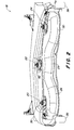
- FIG 2 more closely illustrates the cutting deck 18 that is shown attached to the tractor 10 of Figure 1.
- the deck 18 includes three cutting spindles 20, 22 and 24 that are mounted with three cutting chambers 26, 28 and 30, respectively oriented from left to right, which each house or enclose a blade 32, 34 or 36 respectively therein, as shown in Figures 2 and 4.
- Adjacent right chamber 36 is a discharge opening 37 through which vegetation is thrown or expelled after it is cut.
- Attached to the front and each of the four corner areas of the deck are anti-scalp wheels 38 used to carry the deck 18 over unexpected changes in elevation in the ground that is traveled by the vehicle 10.
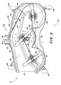
- the underside 40 of the deck includes a lip 42 at the front edge 44 thereof and, particularly, at the front edge 46 of the center chamber 28.
- the lip 42 is provided as part of the construction of the deck 18 and does not bow laterally outwardly any more than any other part of the deck's edge 44 except to the extent that the curvature along a specific length of that front edge 46 of the center chamber 28 may require. Construction of the lip 42 in this manner permits decreased contact with vegetation in the implement's travel path so as to permit the center blade 34 to be as effective as possible in being able to adequately lift and cut that vegetation.
- the lip 42 extends vertically downward from the top surface 48 of the deck 18 and into the cutting plane of the center blade 34.
- the lip 42 is positioned to be off-center, or to the right, of the midpoint A of the center blade 34.
- the blade 34 rotates, it passes through an axis Y, shown therein, that extends through the midpoint A and which is perpendicular to the longitudinal axis of the deck 18.
- the blade conducts a forward sweep of the grass as indicated by the arrows.
- the deck 18 includes a second debris shielding arrangement 52.
- the arrangement includes a first baffle 54 for also shielding debris and directing the flow of vegetation that is cut, primarily, by the left blade 32 and, to a lesser extent, the center blade 34 as well.
- the baffle 54 is, preferably, made of steel or a similar metal, and is mounted to the top surface 56 of the underside 40 of the deck 18 by welding.
- the baffle 54 includes a notch 58 that is of a size and width to permit vegetation that has been bent over by the tractor's left front tire to be able to stand back up prior to meeting the left blade 32. With this notch 58, vegetation traveled by the deck 18 can be adequately and properly cut as the tractor 10 passes.
- the baffle 54 is constructed to carry a second baffle or plate 60 thereon, the positioning of which is to the left of the lip 42 and center line of the center blade 34.
- This second baffle 60 is provided to be adjustable within and is securable to the first baffle 54 at its mounting slots 62 with bolts 64. Adjustably securing the baffle 60 in this manner and location allows it to be extended into the cutting planes of both the left and center blades 32 and 34 to a point where it can be even with the bottom edge 66 of the lip 42. With such an extension capability, the baffle 54 is effectively a continuation of the lip 42 in an area in which blowout of drier vegetation and other debris is likely and has been most frequently noticed. Additionally, the center blade 34 and left blade 32 will conduct the same forward and rearward sweeps mentioned in relation to the lip 42.
- an implement that reduces the likelihood that dried vegetation and other debris will escape the implement when they are impacted and then be thrown from the blades thereof.
Landscapes
- Life Sciences & Earth Sciences (AREA)
- Environmental Sciences (AREA)
- Harvester Elements (AREA)
Abstract
Description
- This invention relates to a cutting implement usable with a vehicle, the implement comprising at least first and second cutting chambers positioned near one another, each of the chambers having a laterally extending front edge on an exterior thereof, first and second cutting blades centered within each of the first and second chambers and rotatable therein to define a cutting plane along which vegetation may be cut and to a vehicle for lawn-, garden- and yard-care.
- Multiple blade cutting implements frequently consist of three separate chambers or adjoining enclosures which contain a respective cutting blade therein. As each of the blades rotates within its chamber to cut vegetation beneath it, an air flow is created with respect to the direction in which the vegetation moves after it is cut and until it is discharged from the implement. Typically in the case of three chamber decks having, respectively, a left, center and right hand chamber, this flow moves from the left chamber towards the right chamber and thereafter exits through a discharge opening in the implement.
- It has been noticed that upon movement of the above flow from the left to center chambers, a sizeable amount of vegetation that is cut is blown out in front of the center chamber. As used therein, "blown out" refers to the condition where cut material is propelled out of the cutting chambers below the edges thereof and thus the front wall of the implement. This condition occurs as a result of the throwing action of the center blade as it contacts vegetation moving from the left chamber and attempts to convey this vegetation through the center chamber and remainder of the implement. Further, the condition is most noticeable when the vegetation that is being cut is dry and, consequently, lighter than it might otherwise be thereby permitting it to be more easily dispersed within the implement.
- To help retain material that is cut or disturbed by their blades, cutting implements or decks of the type described above are typically constructed with skirts or walls which extend downwardly from their top surfaces. When constructed, however, these skirts are often manufactured to be higher at the fronts of the decks than they are at the rear portions thereof. As a result, the cutting plane of the blade carried within a particular chamber falls slightly below the lowest portion of the front of a particular deck, thereby leaving an open gap. With this type of construction, a number of concerns have arisen.
- Among these concerns are the appearance of the lawn or grass after it has been cut by an implement having the above construction. With skirts having this type of design, vegetation and other debris that is cut and/or caught up in the discharge stream often tends to escape the deck below its front edge. This escape of material commonly has occurred at the middle and right front portion(s) of the center chamber. Consequently, an unkept appearance of one's grounds results, thereby requiring an operator to spend additional time and effort in maintaining their appearance.
- Further, past designs which have sought to address the above difficulty -of dry and other material being thrown from the underside of the deck have sought to address the above concerns by providing a horizontal or vertical baffle which extends across the front edge of the deck in the area of the center chamber. This first baffle has been constructed to be even with and extend horizontally inwardly from the deck's front edge. In providing this form or type of solution, the attempt to close the above mentioned gap has not been successful since the baffle has not extended below the cutting plane of the blade. Thus, material such as vegetation and other debris has still escaped through the described gap.
- Still further, a vertical baffle has also been used as stated above. This baffle has extended downwardly from the front of the deck and, like the horizontal baffle above, has decreased the cutting performance of the implement on which it is used. This decrease in performance results from an increased amount of structure at the deck's front edge which knocks down the grass and other vegetation in its path. Since the baffle is vertical and serves as a downward continuation of the deck's edge across the front of the center chamber, vegetation of the type mentioned is bent over for a longer period of time than it would otherwise be if some other device or shielding mechanism were used. As a consequence of being taken out of its upright stance for the period of time that it is in contact with the baffle, it has been observed that the vegetation does not have enough time to be lifted or raised by the cutting blade(s). Accordingly, cutting of the vegetation cannot occur as it should because the grass is still bent over when the time arrives for the cutting edge of the blade to slice a particular piece of grass or other type of vegetation.
- JP-A-01010913 shows a three-chamber mower deck having baffles located in respective areas between the chambers and extending from the top of the mower deck into the chamber to redirect the stream of cut material and therefore keep material from leaving the mower deck. Such baffles tend to support clogging of the mower deck in particular in moist conditions.
- DE-A1-34 19 358 pictures an implement built as a multi-spindle mower deck containing a plurality of mower blades rotatably supported in a deck housing. A plurality of blow-out plates are located in areas between the single chambers and are mounted to the forward sidewall of the housing below the mower deck and extend horizontally inwards there from. This embodiment tends to clogging and does not provide optimal results.
- Thus, it is the object of the present invention to provides a device that forms a part of the deck so as to enable vegetation and other debris that is contacted by the blade(s) thereof from escaping from the underside of the deck and, especially, from the center chamber thereof.
- Accordingly; there is provided a device that forms part of the deck and acts as a shield or guard to assist in retaining vegetation and other debris that is cut and/or disturbed by the deck's blade(s) from leaving its respective cutting chambers. The section serves to substantially shield the vegetation and other debris from exiting the implement after being contacted by at least one of the blades therein.
- Further, the implement can be provided with an adjustable extension to the previous device so as to further insure that an operator is permitted to maintain the overall appearance of the grounds. These capabilities are provided without reducing the maximum level of cutting performance that is obtainable from the deck.
- Specifically, the first of the two above devices can be provided in the form of a lip that is made integral with, or as one-piece of, the front edge of the deck.
- The lip can be extended vertically downwardly into the cutting plane of, particularly, the center blade. Moreover, it can be constructed to sit off to the left of the midpoint of the center blade. It is in this area that the streams of cut material from the two adjacent blades converge. Positioning the lip in this manner substantially decreases the likelihood that vegetation which has been cut and debris that has been disturbed will escape from the center chamber, and thus the deck itself.
- To further insure against the ability of the center blade to project items beyond the structure of the center and at least one other adjoining chamber, the second device can be provided as an adjustable extension to the lip. This extension may be made part of the implement when its operator finds a desire or need for its use insofar as the escape of materials from the area in which the left and center chambers border each other is noticed.
- Accordingly, there is provided an implement which substantially reduces the likelihood of vegetation and other debris escaping there from and, particularly, from the center chamber thereof. In reducing that likelihood, the implement helps to insure the overall appearance of one's grounds.
-
- FIG. 1
- is a side view of a lawn and garden tractor having an implement in the form of a cutting deck mounted at its mid-portion.
- FIG. 2
- is a rear perspective view of the deck shown in FIG. 1.
- FIG. 3
- is a bottom view of the underside of the deck and is shown to include the lip of the present invention.
- FIG. 4
- is a rear view of the deck illustrating its underside including the lip, a baffle forming an extension thereof and the relationship of both relative to the cutting planes of the blades enclosed by the deck.
- FIG. 5
- is a rear elevated view of the deck according to FIG. 4 and is provided to illustrate the placement of the lip relative to the center line of the center blade.
- Looking to Figure 1, there is provided a lawn and garden tractor or a vehicle for lawn-, garden- and yard-
care 10 supported upon a plurality of groundengaging wheels 12, aseat 14 and asteering wheel 16 located in front thereof. Further included as part of the tractor is a multi-chamber cutting implement ordeck 18 mounted to the middle thereof. - Figure 2 more closely illustrates the
cutting deck 18 that is shown attached to thetractor 10 of Figure 1. Thedeck 18 includes threecutting spindles cutting chambers blade right chamber 36 is a discharge opening 37 through which vegetation is thrown or expelled after it is cut. Attached to the front and each of the four corner areas of the deck areanti-scalp wheels 38 used to carry thedeck 18 over unexpected changes in elevation in the ground that is traveled by thevehicle 10. - Referring now to Figures 3 and 4, it can be seen that the
underside 40 of the deck includes alip 42 at thefront edge 44 thereof and, particularly, at thefront edge 46 of thecenter chamber 28. As can be understood from the figures, thelip 42 is provided as part of the construction of thedeck 18 and does not bow laterally outwardly any more than any other part of the deck'sedge 44 except to the extent that the curvature along a specific length of thatfront edge 46 of thecenter chamber 28 may require. Construction of thelip 42 in this manner permits decreased contact with vegetation in the implement's travel path so as to permit thecenter blade 34 to be as effective as possible in being able to adequately lift and cut that vegetation. - Looking now to Figure 5, it can further be seen that the
lip 42 extends vertically downward from thetop surface 48 of thedeck 18 and into the cutting plane of thecenter blade 34. Thelip 42 is positioned to be off-center, or to the right, of the midpoint A of thecenter blade 34. Referring to Figure 3, as theblade 34 rotates, it passes through an axis Y, shown therein, that extends through the midpoint A and which is perpendicular to the longitudinal axis of thedeck 18. On a right hand side of thedeck 18 at midpoint A (the left hand side of the axis Y as shown in Figure 3), the blade conducts a forward sweep of the grass as indicated by the arrows. Grass on this side is adequately cut since thelip 42 is shortened, as shown in Figure 5, so as not to extend across the path of the cutting edge of theblade 34 and because the cutting plane of the blade is- slightly lower than the front -edge of the deck. On a left hand side of thedeck 18 at midpoint A (the right hand side of the axis Y as shown in Figure 3), theblade 34 enters into a rearward sweep as shown by the arrows. In this rearward sweep, grass contacted by thelip 42 is bent forwardly. When in this stance, the grass is bent towards or into the cutting path or plane of theblade 34 and therefore adequately lifted and cut by the blade even though it has contacted thelip 42. With this positioning and in view of the clockwise (counterclockwise when viewed from the underside of the deck as in Figure 3) rotation of theblades center blade 34 towards the front insidewall 50 of thechamber 28 is shielded by thelip 42 at the point where the streams of air and cut material from the left andcenter chambers deck 18, thereby reducing the effects of materials being dispersed from theunderside 40 thereof. - Additionally, the
deck 18 includes a seconddebris shielding arrangement 52. As seen in Figures 4 and 5, the arrangement includes afirst baffle 54 for also shielding debris and directing the flow of vegetation that is cut, primarily, by theleft blade 32 and, to a lesser extent, thecenter blade 34 as well. Thebaffle 54 is, preferably, made of steel or a similar metal, and is mounted to thetop surface 56 of theunderside 40 of thedeck 18 by welding. As can further be seen, thebaffle 54 includes anotch 58 that is of a size and width to permit vegetation that has been bent over by the tractor's left front tire to be able to stand back up prior to meeting theleft blade 32. With thisnotch 58, vegetation traveled by thedeck 18 can be adequately and properly cut as thetractor 10 passes. - Still referring to Figures 4 and 5, the
baffle 54 is constructed to carry a second baffle orplate 60 thereon, the positioning of which is to the left of thelip 42 and center line of thecenter blade 34. Thissecond baffle 60 is provided to be adjustable within and is securable to thefirst baffle 54 at its mountingslots 62 withbolts 64. Adjustably securing thebaffle 60 in this manner and location allows it to be extended into the cutting planes of both the left andcenter blades bottom edge 66 of thelip 42. With such an extension capability, thebaffle 54 is effectively a continuation of thelip 42 in an area in which blowout of drier vegetation and other debris is likely and has been most frequently noticed. Additionally, thecenter blade 34 and leftblade 32 will conduct the same forward and rearward sweeps mentioned in relation to thelip 42. - Thus, there is provided an implement that reduces the likelihood that dried vegetation and other debris will escape the implement when they are impacted and then be thrown from the blades thereof.
- Having described the preferred embodiment, it will become apparent that various modifications can be made without departing from the scope of the invention as defined in the accompanying claims.
Claims (10)
- A cutting implement (18) usable with a vehicle (10), the implement comprising at least first and second cutting chambers (26, 28, 30) positioned near one another, each of the chambers (26, 28, 30) having a laterally extending front edge (44) on an exterior thereof, first and second cutting blades (32, 34, 36) centered within each of the first and second chambers (26, 28, 30) and rotatable therein to define a cutting plane along which vegetation may be cut characterized by a generally vertically extending section depending from and formed on the front edge (44) of one of the chambers (26, 28, 30).
- The implement as recited in claim 1 characterized in that the section extends into the cutting plane of the at least one of the blades (32, 34, 36).
- The implement as recited in claim 1 or 2 characterized in that the midpoint of the section is off center from the midpoint of the at least one of the blades (32, 34, 36).
- The implement as recited in one or several of the previous claims characterized in that the section is a lip (42).
- The implement as recited in one or several of the previous claims characterized by a first baffle (54) carried within the chamber (26) of the other blade (32) for shielding material projected by the other blade (32).
- The implement as recited in claim 5 characterized in that the baffle (54) is arcuately shaped and spans portions of both the first and second chambers (26, 28, 30).
- The implement as recited in claim 5 or 6 characterized in that the baffle (54) includes a notched section thereon that is alignable with one of the front wheels (12) of the vehicle (10) with which the implement (18) may be used.
- The implement as recited in one or several of the claims 5 to 6 characterized in that the first baffle (54) carries a second baffle (60) thereon for shielding material projected by the at least one of the blades (32, 34, 36) from exiting the implement (18) upon being contacted thereby.
- The implement as recited in one or several of the claims 5 to 7 characterized in that the second baffle (60) is adjustable so as to align with a bottom portion of the generally vertically extending section so as to also extend into the cutting planes of both the first and second blades (32, 34, 36).
- Vehicle (10) for lawn-, garden- and yard-care having at least one implement as recited in one or several of the previous claims.
Applications Claiming Priority (2)
| Application Number | Priority Date | Filing Date | Title |
|---|---|---|---|
| US902084 | 2001-07-09 | ||
| US09/902,084 US6779328B2 (en) | 2001-07-09 | 2001-07-09 | Cutting implement having anti-blowout lip and extension |
Publications (2)
| Publication Number | Publication Date |
|---|---|
| EP1275284A1 true EP1275284A1 (en) | 2003-01-15 |
| EP1275284B1 EP1275284B1 (en) | 2006-03-29 |
Family
ID=25415277
Family Applications (1)
| Application Number | Title | Priority Date | Filing Date |
|---|---|---|---|
| EP02014765A Expired - Lifetime EP1275284B1 (en) | 2001-07-09 | 2002-07-04 | Cutting implement and vehicle for lawn-, garden- and yard care |
Country Status (3)
| Country | Link |
|---|---|
| US (1) | US6779328B2 (en) |
| EP (1) | EP1275284B1 (en) |
| DE (1) | DE60210169T2 (en) |
Cited By (1)
| Publication number | Priority date | Publication date | Assignee | Title |
|---|---|---|---|---|
| WO2024064152A1 (en) * | 2022-09-20 | 2024-03-28 | Mtd Products Inc | High efficiency mow deck and multi-blade cutting system for ride-on lawn maintenance apparatus |
Families Citing this family (16)
| Publication number | Priority date | Publication date | Assignee | Title |
|---|---|---|---|---|
| US20050268588A1 (en) * | 2004-06-03 | 2005-12-08 | Winter Jerrod N | Mower cutting deck having blow-out baffle, and method of using same |
| USD563436S1 (en) | 2006-01-28 | 2008-03-04 | Williams Thomas E | Mower deck grass clipping retention apparatus |
| JP4928172B2 (en) * | 2006-06-15 | 2012-05-09 | 株式会社クボタ | Moore |
| US7665286B2 (en) * | 2008-04-04 | 2010-02-23 | Butler Walter R | Mulch deck attachment baffle system |
| US8171709B1 (en) | 2010-10-27 | 2012-05-08 | Schiller Grounds Care, Inc. | Mower baffle system |
| US9756782B2 (en) * | 2013-11-12 | 2017-09-12 | Exmark Mfg. Co., Inc. | Rear discharge mower deck with flow control baffles |
| EP3244720B1 (en) * | 2015-01-12 | 2019-08-07 | Husqvarna AB | Cutting deck flow control assembly |
| EP3302020B1 (en) | 2015-05-27 | 2020-04-08 | MTD Products Inc | Self-cleaning mower blade assembly |
| USD797530S1 (en) | 2015-06-05 | 2017-09-19 | Mtd Products Inc | Blade |
| USD795299S1 (en) | 2016-02-16 | 2017-08-22 | Mtd Products Inc | Blade |
| CA3021508C (en) | 2016-04-20 | 2020-09-08 | Mtd Products Inc | Low-energy blade system having a quick-attach mechanism |
| WO2017223568A1 (en) | 2016-06-24 | 2017-12-28 | Mtd Products Inc | High-efficiency cutting system |
| USD795300S1 (en) | 2016-08-23 | 2017-08-22 | Mtd Products Inc | Blade |
| WO2019071061A1 (en) | 2017-10-06 | 2019-04-11 | Mtd Products Inc | High-efficiency lawn maintenance tool and high-efficiency cutting blade |
| US11234365B2 (en) | 2017-10-31 | 2022-02-01 | Clark Equipment Company | Baffles for mower deck |
| DE102019134415B4 (en) * | 2019-12-13 | 2023-12-14 | Festool Gmbh | Mobile hand sawing machine with scoring unit and dust removal |
Citations (4)
| Publication number | Priority date | Publication date | Assignee | Title |
|---|---|---|---|---|
| US2898723A (en) * | 1956-06-15 | 1959-08-11 | Goodall Equipment Inc | Multiple bladed mower |
| FR2548864A1 (en) * | 1983-06-27 | 1985-01-18 | Deere & Co | Agricultural crop reaping machine |
| US5251430A (en) * | 1990-08-10 | 1993-10-12 | Honda Giken Kogyo Kabushiki Kaisha | Cutter and housing assembly for lawn mower |
| GB2347838A (en) * | 1999-03-10 | 2000-09-20 | Scag Power Equipment Inc | Lawn mower |
Family Cites Families (21)
| Publication number | Priority date | Publication date | Assignee | Title |
|---|---|---|---|---|
| US3851452A (en) * | 1970-01-23 | 1974-12-03 | A Brocas | Guarded rotary mowers |
| US3673772A (en) | 1970-12-17 | 1972-07-04 | Deere & Co | Impact mowing machine |
| US4502271A (en) * | 1983-01-28 | 1985-03-05 | Outboard Marine Corporation | Rear discharge multi-blade rotary mower |
| US4543773A (en) * | 1983-06-27 | 1985-10-01 | Deere & Company | Anti-blowout plate for multi-spindle mower decks |
| JPS6410913A (en) | 1987-07-03 | 1989-01-13 | Kubota Ltd | Mower deck structure of mower |
| FR2643213A1 (en) | 1989-02-17 | 1990-08-24 | Eurl Duyck | Mower |
| US5191756A (en) | 1991-02-04 | 1993-03-09 | Deere & Company | Mulching mower apparatus |
| US5457947A (en) | 1992-07-02 | 1995-10-17 | Kubota Corporation | Mulching mower unit |
| US5267429A (en) | 1992-07-21 | 1993-12-07 | Deere & Company | Rear discharge mulching apparatus |
| US5483790A (en) | 1993-09-15 | 1996-01-16 | Deere & Company | Rotating mower baffle mechanism |
| US5488821A (en) | 1994-11-09 | 1996-02-06 | Deere & Company | Mulching mower mechanism |
| DE29512057U1 (en) | 1995-07-26 | 1995-11-16 | Sperber Maschinenbau GmbH & Co., 90765 Fürth | Mower with bar-shaped cutting blades |
| US5845475A (en) | 1995-11-16 | 1998-12-08 | Exmark Mfg. Co., Inc. | Lawn mower having flow control baffles and removable mulching baffles |
| US5921072A (en) * | 1996-06-27 | 1999-07-13 | Cargile; W. Allen | Mulching lawn mower with vertical cutting and improved discharge action and clipping deposit |
| US6065276A (en) * | 1997-01-24 | 2000-05-23 | Deere & Company | Mulching mower deck |
| US5884466A (en) * | 1997-02-05 | 1999-03-23 | White Consolidated Industries, Inc. | Plastic deck liner for lawn mower |
| US5765346A (en) | 1997-03-24 | 1998-06-16 | Deere & Company | Mower deck |
| JP3391653B2 (en) | 1997-04-16 | 2003-03-31 | 株式会社クボタ | Rear discharge mower unit and lawn mower |
| US5860272A (en) | 1997-09-26 | 1999-01-19 | Griffin; Ronald H. | Mower belt housing hole cover |
| US6189307B1 (en) * | 1999-02-16 | 2001-02-20 | Deere & Company | Fastener assembly for attachment of composite insert to mower deck |
| DE10044595A1 (en) | 2000-09-09 | 2002-04-04 | Roberine Bv Enschede | Mower, deflector device and vehicle or device |
-
2001
- 2001-07-09 US US09/902,084 patent/US6779328B2/en not_active Expired - Lifetime
-
2002
- 2002-07-04 DE DE60210169T patent/DE60210169T2/en not_active Expired - Lifetime
- 2002-07-04 EP EP02014765A patent/EP1275284B1/en not_active Expired - Lifetime
Patent Citations (4)
| Publication number | Priority date | Publication date | Assignee | Title |
|---|---|---|---|---|
| US2898723A (en) * | 1956-06-15 | 1959-08-11 | Goodall Equipment Inc | Multiple bladed mower |
| FR2548864A1 (en) * | 1983-06-27 | 1985-01-18 | Deere & Co | Agricultural crop reaping machine |
| US5251430A (en) * | 1990-08-10 | 1993-10-12 | Honda Giken Kogyo Kabushiki Kaisha | Cutter and housing assembly for lawn mower |
| GB2347838A (en) * | 1999-03-10 | 2000-09-20 | Scag Power Equipment Inc | Lawn mower |
Cited By (1)
| Publication number | Priority date | Publication date | Assignee | Title |
|---|---|---|---|---|
| WO2024064152A1 (en) * | 2022-09-20 | 2024-03-28 | Mtd Products Inc | High efficiency mow deck and multi-blade cutting system for ride-on lawn maintenance apparatus |
Also Published As
| Publication number | Publication date |
|---|---|
| US6779328B2 (en) | 2004-08-24 |
| EP1275284B1 (en) | 2006-03-29 |
| DE60210169T2 (en) | 2006-08-17 |
| US20030005680A1 (en) | 2003-01-09 |
| DE60210169D1 (en) | 2006-05-18 |
Similar Documents
| Publication | Publication Date | Title |
|---|---|---|
| EP1275284B1 (en) | Cutting implement and vehicle for lawn-, garden- and yard care | |
| US5987863A (en) | Lawn mower having flow control baffles and removable mulching baffles | |
| US6681553B2 (en) | Mower cutting chamber | |
| US4591102A (en) | Chaff spreader for combine harvester | |
| US5133176A (en) | Multi-bladed mulching mower | |
| US5191756A (en) | Mulching mower apparatus | |
| US5465564A (en) | Convertible mower deck | |
| CA2087875C (en) | Rear discharge mulching apparatus | |
| US5021030A (en) | Straw spreader for a combine harvester and method of spreading | |
| US4502271A (en) | Rear discharge multi-blade rotary mower | |
| US6116010A (en) | Knife guard for a cutterbar assembly | |
| US6571544B1 (en) | Cutting implement having notched front flow baffle | |
| GB1581370A (en) | Rotary lawnmower | |
| US8091332B2 (en) | Mower deck with air inlets | |
| US5421777A (en) | Tailings return system for combine harvester | |
| CA1269905A (en) | Grain deflector for combines | |
| US4970852A (en) | Grass catcher for reel mower | |
| CA2102817C (en) | Combine harvester with dust collection | |
| US3799579A (en) | Rear shield for rotary lawnmower | |
| US3971199A (en) | Blade guard for rotary lawn mowers | |
| US7024847B2 (en) | Mower deck | |
| JP2003174815A (en) | General purpose combine harvester | |
| US5566534A (en) | Floatation cutting apparatus with centrifuge chamber | |
| US3673772A (en) | Impact mowing machine | |
| US5816299A (en) | Disc saw felling head chip discharge |
Legal Events
| Date | Code | Title | Description |
|---|---|---|---|
| PUAI | Public reference made under article 153(3) epc to a published international application that has entered the european phase |
Free format text: ORIGINAL CODE: 0009012 |
|
| AK | Designated contracting states |
Kind code of ref document: A1 Designated state(s): AT BE BG CH CY CZ DE DK EE ES FI FR GB GR IE IT LI LU MC NL PT SE SK TR |
|
| AX | Request for extension of the european patent |
Free format text: AL;LT;LV;MK;RO;SI |
|
| 17P | Request for examination filed |
Effective date: 20030715 |
|
| AKX | Designation fees paid |
Designated state(s): DE FR GB |
|
| GRAP | Despatch of communication of intention to grant a patent |
Free format text: ORIGINAL CODE: EPIDOSNIGR1 |
|
| GRAS | Grant fee paid |
Free format text: ORIGINAL CODE: EPIDOSNIGR3 |
|
| GRAA | (expected) grant |
Free format text: ORIGINAL CODE: 0009210 |
|
| AK | Designated contracting states |
Kind code of ref document: B1 Designated state(s): DE FR GB |
|
| REG | Reference to a national code |
Ref country code: GB Ref legal event code: FG4D |
|
| REF | Corresponds to: |
Ref document number: 60210169 Country of ref document: DE Date of ref document: 20060518 Kind code of ref document: P |
|
| ET | Fr: translation filed | ||
| PLBE | No opposition filed within time limit |
Free format text: ORIGINAL CODE: 0009261 |
|
| STAA | Information on the status of an ep patent application or granted ep patent |
Free format text: STATUS: NO OPPOSITION FILED WITHIN TIME LIMIT |
|
| 26N | No opposition filed |
Effective date: 20070102 |
|
| PGFP | Annual fee paid to national office [announced via postgrant information from national office to epo] |
Ref country code: FR Payment date: 20080729 Year of fee payment: 7 |
|
| REG | Reference to a national code |
Ref country code: FR Ref legal event code: ST Effective date: 20100331 |
|
| PG25 | Lapsed in a contracting state [announced via postgrant information from national office to epo] |
Ref country code: FR Free format text: LAPSE BECAUSE OF NON-PAYMENT OF DUE FEES Effective date: 20090731 |
|
| PGFP | Annual fee paid to national office [announced via postgrant information from national office to epo] |
Ref country code: DE Payment date: 20140619 Year of fee payment: 13 |
|
| REG | Reference to a national code |
Ref country code: DE Ref legal event code: R119 Ref document number: 60210169 Country of ref document: DE |
|
| PG25 | Lapsed in a contracting state [announced via postgrant information from national office to epo] |
Ref country code: DE Free format text: LAPSE BECAUSE OF NON-PAYMENT OF DUE FEES Effective date: 20160202 |
|
| PGFP | Annual fee paid to national office [announced via postgrant information from national office to epo] |
Ref country code: GB Payment date: 20210727 Year of fee payment: 20 |
|
| REG | Reference to a national code |
Ref country code: GB Ref legal event code: PE20 Expiry date: 20220703 |
|
| PG25 | Lapsed in a contracting state [announced via postgrant information from national office to epo] |
Ref country code: GB Free format text: LAPSE BECAUSE OF EXPIRATION OF PROTECTION Effective date: 20220703 |