EP1275192B1 - Rotor, rotor assembly, method and machine for manufacture of rotor elements - Google Patents
Rotor, rotor assembly, method and machine for manufacture of rotor elements Download PDFInfo
- Publication number
- EP1275192B1 EP1275192B1 EP01911992A EP01911992A EP1275192B1 EP 1275192 B1 EP1275192 B1 EP 1275192B1 EP 01911992 A EP01911992 A EP 01911992A EP 01911992 A EP01911992 A EP 01911992A EP 1275192 B1 EP1275192 B1 EP 1275192B1
- Authority
- EP
- European Patent Office
- Prior art keywords
- elements
- die
- pole
- die member
- rotor
- Prior art date
- Legal status (The legal status is an assumption and is not a legal conclusion. Google has not performed a legal analysis and makes no representation as to the accuracy of the status listed.)
- Expired - Lifetime
Links
Images


Classifications
-
- H—ELECTRICITY
- H02—GENERATION; CONVERSION OR DISTRIBUTION OF ELECTRIC POWER
- H02K—DYNAMO-ELECTRIC MACHINES
- H02K15/00—Methods or apparatus specially adapted for manufacturing, assembling, maintaining or repairing of dynamo-electric machines
- H02K15/02—Methods or apparatus specially adapted for manufacturing, assembling, maintaining or repairing of dynamo-electric machines of stator or rotor bodies
- H02K15/022—Methods or apparatus specially adapted for manufacturing, assembling, maintaining or repairing of dynamo-electric machines of stator or rotor bodies with salient poles or claw-shaped poles
-
- H—ELECTRICITY
- H02—GENERATION; CONVERSION OR DISTRIBUTION OF ELECTRIC POWER
- H02K—DYNAMO-ELECTRIC MACHINES
- H02K1/00—Details of the magnetic circuit
- H02K1/06—Details of the magnetic circuit characterised by the shape, form or construction
- H02K1/22—Rotating parts of the magnetic circuit
- H02K1/24—Rotor cores with salient poles ; Variable reluctance rotors
-
- Y—GENERAL TAGGING OF NEW TECHNOLOGICAL DEVELOPMENTS; GENERAL TAGGING OF CROSS-SECTIONAL TECHNOLOGIES SPANNING OVER SEVERAL SECTIONS OF THE IPC; TECHNICAL SUBJECTS COVERED BY FORMER USPC CROSS-REFERENCE ART COLLECTIONS [XRACs] AND DIGESTS
- Y10—TECHNICAL SUBJECTS COVERED BY FORMER USPC
- Y10T—TECHNICAL SUBJECTS COVERED BY FORMER US CLASSIFICATION
- Y10T29/00—Metal working
- Y10T29/49—Method of mechanical manufacture
- Y10T29/49002—Electrical device making
- Y10T29/49009—Dynamoelectric machine
-
- Y—GENERAL TAGGING OF NEW TECHNOLOGICAL DEVELOPMENTS; GENERAL TAGGING OF CROSS-SECTIONAL TECHNOLOGIES SPANNING OVER SEVERAL SECTIONS OF THE IPC; TECHNICAL SUBJECTS COVERED BY FORMER USPC CROSS-REFERENCE ART COLLECTIONS [XRACs] AND DIGESTS
- Y10—TECHNICAL SUBJECTS COVERED BY FORMER USPC
- Y10T—TECHNICAL SUBJECTS COVERED BY FORMER US CLASSIFICATION
- Y10T83/00—Cutting
- Y10T83/929—Tool or tool with support
- Y10T83/9457—Joint or connection
- Y10T83/9473—For rectilinearly reciprocating tool
- Y10T83/9483—Adjustable
- Y10T83/9486—Rectilinearly
Definitions
- This invention is concerned with a machine for the manufacture of elements for electric motors, which term is to be deemed to include generators, and is particularly concerned with motors of the type comprising a fixed stator defining a generally hollow cylindrical chamber, and a rotor assembly comprising a shaft, adapted to be mounted within the stator, and a plurality of rotor members extending radially of the shaft.
- a conventional rotor member for a motor is constructed from a plurality of rotor elements, conveniently in the form of steel pressings, conventionally of about 1mm in thickness which lie in or parallel to a plane extending at right angles to the axis of the rotor.
- each rotor element comprises a body portion, and positioned radially outwardly of the body portion, a pole portion having an extended outer surface which has a radius of curvature marginally smaller than that of the stator surface, there being a small air gap between the outer surface of the pole portion and the inner surface of the stator.
- each rotor element is formed integrally as a pressing from (for example) a steel strip, the rotor being assembled by a jig in which the rotor elements are secured together in a desired orientation.
- pole plates Whilst this may be accomplished by welding the pole plates to the body plates individually, it has been found convenient to assemble the pole plates and body plates in appropriate jigs, and to secure the pole plates to the body plates by welding along an interface corner on each of two opposite sides.
- rotor elements may be produced which have pole portions which are offset by different distances relative to a centre line of the body portion.
- the part of the (first) pole portion which is produced by the first die member is that part of the pole portion which is common to all rotor elements throughout the range.
- the die assembly includes a third die member for providing by punching a peripheral margin which may be curved and defines a curved outer surface of the pole portion, between the first portion of an element and a second portion of an element made by a preceding punching operation.
- a third die member for providing by punching a peripheral margin which may be curved and defines a curved outer surface of the pole portion, between the first portion of an element and a second portion of an element made by a preceding punching operation.
- the second and third die members are integral, the third die member moving in the performance of the method with the second die member.
- the machine comprises means to cause all the die members thereof to perform a punching operation simultaneously.
- Figure 1 shows a conventional rotor assembly comprising a shaft 6, and a plurality of rotor elements 8 connected to the shaft for rotation therewith about the axis A-A of the shaft 6, each rotor element comprising a body portion 10 and a pole portion 12.
- the rotor elements are typically 1mm in thickness, and are stacked to a desired depth in the longitudinal direction, whilst the pole portions 12 are provided with curved outer surfaces 13, having a radius of curvature marginally smaller than the radius of curvature of the stator in which they are to be mounted, whereby a small air gap is provided between the rotor and the stator.
- Figure 2 illustrates schematically a modified construction of rotor, in which, whilst the body portions are retained in position, the pole portions 12 are progressively offset in both axial directions from a central plane B-B to produce a "chevron" appearance as can be seen in Figure 2.
- each pole portion differs in relation to an adjacent pole element, with respect of the centre line C/L of the body portion 10, and thus the rotor elements cannot conveniently be produced by the conventional stamping operation.
- Figure 3 which illustrates the variation in location of the pole portions 12 in relation to the body portions 8, it is conventional to manufacture the body portions and pole portions separately, and to secure these together, conveniently subsequent to assembly of the elements in a jig, by weld lines X disposed at two interfacial corners between the pole elements and the body elements.
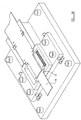
- Figure 4 a is a perspective view illustrating a die assembly, also illustrative of certain aspects of this invention, utilised for the performance of a method of producing rotor elements whereby a rotor assembly of the preferred "chevron" design may be manufactured more conveniently.
- the die assembly shown in Figure 4 a comprises a base plate 20 upon which a first, stationary member 22 is mounted, and adjacent thereto a second, moving die member 32.
- the die member 22 comprises two die apertures 24 a , 24 b , each providing a die surface which corresponds to part of the periphery of the pole portion of a rotor element.
- the moving die member 32 comprises die apertures 34 a , 34 b each providing a die surface corresponding to one side of a body portion 10, and a third die aperture 35 extending between the two die apertures 34 a and 34 b .
- the die assembly also comprises means 36, comprising driven gear wheels 38 engageable with racks 40, whereby the die member 32 may be moved incrementally back and forth across the base plate 20.
- the die assembly comprises means (not shown) for advancing strip steel 50, conventionally of 1mm thickness, across the die assembly in the operation of the machine, guide means conveniently afforded by pegs 52 engageable within pre-formed apertures 54 in the steel strip being provided accurately to locate the strip 50 in relation to the stationary die member 22 and the moving die member 32.
- Punches (not shown) complimentary to the first die apertures 24 a and 24b will remove portions of material from the steel strip corresponding to the outermost margins of the pole elements of a conventional rotor element.
- the strip is advanced from position B to position C (see also Figure 8), and a punch member 62 comprising punch portions 64 a , and 64 b , corresponding to the apertures 34 a and 34 b respectively, are operated to punch outside the margins of the strip, whilst a third punch member 65, integral with the punch portions 64 a and 64 b , passes into the bridging aperture 35.
- the punch members 64 a and 64 b co-operate with the areas of the strip removed by the punches of the first die assembly, and there is thus produced a completed rotor element 72, at position D.
- the bridging aperture 35 and corresponding punch portion 65 have surfaces provided with radii of curvature R1 and R2, the radius R1 being equal to the desired radius of curvature of the outer surfaces of the pole elements, whilst the radius R2 is equal to the radius of the bottom surface of the rotor.
- the drive means 36 is operated to cause an incremental movement of the die plate 32 in a desired direction, to produce an offset of the pole portion from the centre line C/L of the body portion, such movement incrementally moving to a maximum in one direction, and returning in the opposite direction to a start position.
- the rotor elements which are produced by operation of the machine shown in Figure 4 will be "stacked" in the correct sequence.
- a plurality of rotor elements may be produced with the second die assembly in one location, prior to an incremental movement, and the punching of a plurality of rotor elements in this offset position.
- Figure 4 a shows the second and third die assemblies having been moved to a maximum position in one direction
- Figure 5 a shows the second die assembly having been moved to a position of maximum offset in the opposite direction
- Figure 6 a shows the second die assembly in a medium position, the rotor elements produced by the die assembly in these rotor positions being illustrated in Figures 4 b , 5 b and 6 b respectively.
- the punch element 65 which produces the curved outer surface of the pole element, together with the curved inner surface of the body portion, is produced by the third die assembly, specifically by the punch 65 moving into the die apertures 35, the centre line of the radius of curvature of the pole portions will necessarily remain generally on the centre line C/L of the body portion (see particularly Figure 7), although the offset of the pole portion will be different by one increment from the theoretical position.
- the pole elements will be staggered when the rotor elements are correctly secured together, the centre line of the outer surface will remain constant, and the air gap between the outer surface and the inner surface of the stator will remain constant, despite the fact that a "chevron" arrangement of pole elements is being utilised.
Abstract
Description
- This invention is concerned with a machine for the manufacture of elements for electric motors, which term is to be deemed to include generators, and is particularly concerned with motors of the type comprising a fixed stator defining a generally hollow cylindrical chamber, and a rotor assembly comprising a shaft, adapted to be mounted within the stator, and a plurality of rotor members extending radially of the shaft..
- A conventional rotor member for a motor is constructed from a plurality of rotor elements, conveniently in the form of steel pressings, conventionally of about 1mm in thickness which lie in or parallel to a plane extending at right angles to the axis of the rotor.
- Conventionally each rotor element comprises a body portion, and positioned radially outwardly of the body portion, a pole portion having an extended outer surface which has a radius of curvature marginally smaller than that of the stator surface, there being a small air gap between the outer surface of the pole portion and the inner surface of the stator.
- Conveniently, each rotor element is formed integrally as a pressing from (for example) a steel strip, the rotor being assembled by a jig in which the rotor elements are secured together in a desired orientation.
- It is believed that there may be advantages by offsetting the pole portions in a manner such as to present, in plan view, the appearance of a chevron. Such a rotor construction is described in US A 4616151.
- However, since with such a construction adjacent pole portions have different positions in relation to the body portion dependant upon the position of the rotor element in a direction longitudinally of the shaft, it is not possible to produce such a rotor by stacking a number of identical elements, and to achieve this desired chevron design, it has been found necessary to produce, conveniently by stamping, pole plates separately from the body plates, and to secure these together by welding.
- Whilst this may be accomplished by welding the pole plates to the body plates individually, it has been found convenient to assemble the pole plates and body plates in appropriate jigs, and to secure the pole plates to the body plates by welding along an interface corner on each of two opposite sides.
- Whilst this enables a rotor of the desired chevron profile to be produced relatively simply by the use of semi-automatic machinery, it is nonetheless relatively complicated, and does cause a reduction to the flow of flux to the pole portion.
- Additionally, since identical pole plates are utilised, necessarily the centres of curvature of the outer faces of the pole plates when assembled follow the line of the chevron, rather than, as occurs with the conventional design, having the centres of curvature lying in a radial plane of the rotor, and even though the effect of this is small, it produces a variation in the air gap at the centre, compared with the air gap at the sides of the rotor.
- According to this invention there is provided a machine for the manufacture of elements from strip stock, the elements in use being stacked to provide an assembly of stacked elements for an electrical motor, according to claim 1.
- According to this invention there is also provided a method of manufacturing elements using a machine according to the first aspect of the invention, accordong to claim 7.
- In this way rotor elements may be produced which have pole portions which are offset by different distances relative to a centre line of the body portion.
- Preferably the part of the (first) pole portion which is produced by the first die member is that part of the pole portion which is common to all rotor elements throughout the range.
- Preferably the die assembly includes a third die member for providing by punching a peripheral margin which may be curved and defines a curved outer surface of the pole portion, between the first portion of an element and a second portion of an element made by a preceding punching operation.
- Preferably the second and third die members are integral, the third die member moving in the performance of the method with the second die member.
- Preferably the machine comprises means to cause all the die members thereof to perform a punching operation simultaneously.
- The invention will now be described by way of example with reference to the accompanying drawings wherein:
- FIGURE 1 is a perspective view of a conventional rotor assembly;,
- FIGURE 2 is a plan view of a modified form of rotor assembly of the kind shown in Figure 1, of the known "chevron" design;
- FIGURE 3 is a side elevation of a rotor element utilised in the construction shown in Figure 2;
- FIGURES 4a, 5a and 6a are views of a machine utilised for the production of die elements in accordance with the present invention;
- FIGURES 4b, 5b and 6b are views of rotor elements produced by the die assemblies shown in Figures 4a, 5a and 6a;
- FIGURE 7 is a plan view of a second die member of the machine; and
- FIGURE 8 is a view illustrating the sequential stages in the punching of a rotor element in accordance with this invention, from steel strip material.
- Figure 1 shows a conventional rotor assembly comprising a
shaft 6, and a plurality ofrotor elements 8 connected to the shaft for rotation therewith about the axis A-A of theshaft 6, each rotor element comprising abody portion 10 and apole portion 12. In conventional manner the rotor elements are typically 1mm in thickness, and are stacked to a desired depth in the longitudinal direction, whilst thepole portions 12 are provided with curvedouter surfaces 13, having a radius of curvature marginally smaller than the radius of curvature of the stator in which they are to be mounted, whereby a small air gap is provided between the rotor and the stator. - Figure 2 illustrates schematically a modified construction of rotor, in which, whilst the body portions are retained in position, the
pole portions 12 are progressively offset in both axial directions from a central plane B-B to produce a "chevron" appearance as can be seen in Figure 2. - It will be apparent that in the arrangement shown in Figure 2, the relative position of each pole portion differs in relation to an adjacent pole element, with respect of the centre line C/L of the
body portion 10, and thus the rotor elements cannot conveniently be produced by the conventional stamping operation. Thus as shown in Figure 3, which illustrates the variation in location of thepole portions 12 in relation to thebody portions 8, it is conventional to manufacture the body portions and pole portions separately, and to secure these together, conveniently subsequent to assembly of the elements in a jig, by weld lines X disposed at two interfacial corners between the pole elements and the body elements. - Figure 4a is a perspective view illustrating a die assembly, also illustrative of certain aspects of this invention, utilised for the performance of a method of producing rotor elements whereby a rotor assembly of the preferred "chevron" design may be manufactured more conveniently.
- In accordance with this invention, the die assembly shown in Figure 4a comprises a
base plate 20 upon which a first,stationary member 22 is mounted, and adjacent thereto a second, moving diemember 32. - The die
member 22 comprises twodie apertures 24a, 24b, each providing a die surface which corresponds to part of the periphery of the pole portion of a rotor element. - The moving
die member 32 comprises die apertures 34a, 34b each providing a die surface corresponding to one side of abody portion 10, and athird die aperture 35 extending between the two die apertures 34a and 34b. - The die assembly also comprises means 36, comprising driven
gear wheels 38 engageable withracks 40, whereby the diemember 32 may be moved incrementally back and forth across thebase plate 20. - The die assembly comprises means (not shown) for advancing
strip steel 50, conventionally of 1mm thickness, across the die assembly in the operation of the machine, guide means conveniently afforded bypegs 52 engageable withinpre-formed apertures 54 in the steel strip being provided accurately to locate thestrip 50 in relation to thestationary die member 22 and the movingdie member 32. - The operation of the die assembly will now be described.
- Punches (not shown) complimentary to the
first die apertures 24a and 24b will remove portions of material from the steel strip corresponding to the outermost margins of the pole elements of a conventional rotor element. - The strip is advanced from position B to position C (see also Figure 8), and a
punch member 62 comprising punch portions 64a, and 64b, corresponding to the apertures 34a and 34b respectively, are operated to punch outside the margins of the strip, whilst athird punch member 65, integral with the punch portions 64a and 64b, passes into thebridging aperture 35. - The punch members 64a and 64b co-operate with the areas of the strip removed by the punches of the first die assembly, and there is thus produced a completed rotor element 72, at position D.
- As appears in Figure 7, the
bridging aperture 35 andcorresponding punch portion 65 have surfaces provided with radii of curvature R1 and R2, the radius R1 being equal to the desired radius of curvature of the outer surfaces of the pole elements, whilst the radius R2 is equal to the radius of the bottom surface of the rotor. - It will of course be understood that the punches of both die assemblies are operated simultaneously. Subsequent to each punching operation, the drive means 36 is operated to cause an incremental movement of the
die plate 32 in a desired direction, to produce an offset of the pole portion from the centre line C/L of the body portion, such movement incrementally moving to a maximum in one direction, and returning in the opposite direction to a start position. In this way the rotor elements which are produced by operation of the machine shown in Figure 4 will be "stacked" in the correct sequence. - However, if desired, a plurality of rotor elements may be produced with the second die assembly in one location, prior to an incremental movement, and the punching of a plurality of rotor elements in this offset position.
- Whilst Figure 4a shows the second and third die assemblies having been moved to a maximum position in one direction, Figure 5a shows the second die assembly having been moved to a position of maximum offset in the opposite direction, whilst Figure 6a shows the second die assembly in a medium position, the rotor elements produced by the die assembly in these rotor positions being illustrated in Figures 4b, 5b and 6b respectively.
- Since the
punch element 65 which produces the curved outer surface of the pole element, together with the curved inner surface of the body portion, is produced by the third die assembly, specifically by thepunch 65 moving into thedie apertures 35, the centre line of the radius of curvature of the pole portions will necessarily remain generally on the centre line C/L of the body portion (see particularly Figure 7), although the offset of the pole portion will be different by one increment from the theoretical position. In this manner, although the pole elements will be staggered when the rotor elements are correctly secured together, the centre line of the outer surface will remain constant, and the air gap between the outer surface and the inner surface of the stator will remain constant, despite the fact that a "chevron" arrangement of pole elements is being utilised. - In this way the advantages of the chevron arrangement may be utilised, without the disadvantages of variation of the thickness of the air gap in the direction axially of the rotor assembly.
- In the present specification "comprise" means "includes or consists of' and "comprising" means "including or consisting of".
- The features disclosed in the foregoing description, or the following claims, or the accompanying drawings, expressed in their specific forms or in terms of a means for performing the disclosed function, or a method or process for attaining the disclosed result as appropriate, may, separately, or in any combination of such features whilst falling within the scope of the appended claims, be utilised for realising the invention in diverse forms thereof.
Claims (9)
- A machine for the manufacture of elements (8) from strip stock, the elements (8) in use being stacked to provide an assembly of stacked elements (8) for an electrical motor, each element (8) including body (10) and pole (12) portions which are integrally formed, the machine including a die assembly including a first die member (22) for providing by punching at least parts of the body portions (10) of each element and a second die member (32) for providing by punching, the pole portions (12) of each element (8), and characterised in that the body and pole die members (22, 32) are relatively moveable between successive punching operations when the body and pole portions (10, 12) of the elements (8) are provided, whereby incremental adjustment of the position of the second die member (32) relative to the first die member (22) is effected so that whilst each of the body portions (10) of the elements (8) is provided along a common centre line, the pole portion (12) of each of the successive elements (8) is incrementally offset relative to the pole portion (12) of each of the respective previous elements (8) with respect to the said common centre line of the body portion (10).
- A machine according to claim 1 characterised in that the first die member (22) is maintained stationary relative to a base (20) of the machine, and the second die member (32) is moved incrementally between successive punching operations relative to the first die member (22) and the base (20).
- A machine according to claim 1 or claim 2 characterised in that each of the first and second die members (22, 32) has an associated punch.
- A machine according to any one of claims 1 to 3 characterised in that the die assembly includes a third die member (35) for providing by punching a peripheral margin between the body portion (10) of an element (8) and a pole portion (12) of an element made by a preceding punching operation.
- A machine according to claim 4 characterised in that the peripheral margin of the pole portion is curved.
- A machine according to claim 4 or claim 5 characterised in that the second and third die members (32, 35) are integral.
- A method of manufacturing elements (8) using a machine according to any one of the preceding claims, from strip stock, the elements (8) in use being stacked to provide an assembly of stacked elements (8) for an electrical motor, each element (8) including body (10) and pole (12) portions which are integrally formed, the machine including a die assembly including a first die member (22) for providing by punching at least parts of the body portions (10) of each element and a second die member (32) for providing by punching, the pole portions (12) of each element (8), and characterised in that the method includes relatively moving the first and second die members (22, 32) between successive punching operations when the body and pole portions (10, 12) of the elements (8) are provided, whereby incremental adjustment of the position of the second die member (32) relative to the first die member (22) is effected so that whilst each of the body portions (10) of the elements (8) is provided along a common centre line, the pole portion (12) of each of the successive elements (8) is incrementally offset relative to the pole portion (12) of each of the respective previous elements (8) with respect to the said common centre line.
- A method according to claim 7 characterised in that the die assembly includes a third die member (35) and the method includes providing by punching using the third die member, a peripheral margin between the body portion (10) of an element (8) and a pole portion (12) of an element made by a preceding punching operation.
- A method according to claim 8 characterised in that the third die member (35) is moved with the second die member (32) incrementally between successive punching operations.
Applications Claiming Priority (3)
| Application Number | Priority Date | Filing Date | Title |
|---|---|---|---|
| GB0009248 | 2000-04-15 | ||
| GB0009248A GB2361362B (en) | 2000-04-15 | 2000-04-15 | Improvements relating to electrical motors |
| PCT/GB2001/001220 WO2001080401A1 (en) | 2000-04-15 | 2001-03-20 | Rotor, rotor assembly, method and machine for manufacture of rotor elements |
Publications (2)
| Publication Number | Publication Date |
|---|---|
| EP1275192A1 EP1275192A1 (en) | 2003-01-15 |
| EP1275192B1 true EP1275192B1 (en) | 2007-05-02 |
Family
ID=9889929
Family Applications (1)
| Application Number | Title | Priority Date | Filing Date |
|---|---|---|---|
| EP01911992A Expired - Lifetime EP1275192B1 (en) | 2000-04-15 | 2001-03-20 | Rotor, rotor assembly, method and machine for manufacture of rotor elements |
Country Status (9)
| Country | Link |
|---|---|
| US (1) | US6952943B2 (en) |
| EP (1) | EP1275192B1 (en) |
| AT (1) | ATE361574T1 (en) |
| AU (1) | AU2001240910A1 (en) |
| BR (1) | BR0110088A (en) |
| DE (1) | DE60128214C5 (en) |
| GB (1) | GB2361362B (en) |
| HU (1) | HUP0300476A2 (en) |
| WO (1) | WO2001080401A1 (en) |
Cited By (2)
| Publication number | Priority date | Publication date | Assignee | Title |
|---|---|---|---|---|
| WO2012168238A2 (en) | 2011-06-08 | 2012-12-13 | Wobben Properties Gmbh | Electric machine, synchronous generator-field pole, synchronous generator-rotor comprising a plurality of field poles, and method for producing a synchronous generator-field pole of an electric machine |
| US10483814B2 (en) | 2013-04-08 | 2019-11-19 | Wobben Properties Gmbh | Synchronous-generator pole stack |
Families Citing this family (9)
| Publication number | Priority date | Publication date | Assignee | Title |
|---|---|---|---|---|
| GB2389241A (en) * | 2002-05-29 | 2003-12-03 | Europ Electrical Laminations L | Stator assembly for electric motor |
| CN101375484A (en) | 2006-01-24 | 2009-02-25 | 株式会社安川电机 | Divided core for motor stator, motor stator using it, permanent magnetic type synchronous motor, and punching method using punching mold for divided core |
| DE102009019555A1 (en) * | 2009-04-30 | 2010-11-04 | Minebea Co., Ltd. | Iron core i.e. stator core, for electrical machine e.g. direct current motor, has multiple sheets stacked and rotated against each other around integral multiple of pole distance, and partial pole shoes formed in convex and concave shape |
| DE102010015067B4 (en) | 2010-04-15 | 2014-02-13 | Roos & Kübler GmbH & Co. KG | Method and device for producing laminated cores |
| DE102010040245A1 (en) * | 2010-09-03 | 2012-03-08 | Siemens Aktiengesellschaft | Tooth element for use in stator of electromotor used in e.g. drive of rail vehicle, has tooth head comprising projections, which protrude in parallel and vertical to longitudinal extension of tooth element |
| SI23780A (en) * | 2011-06-02 | 2012-12-31 | Hidria Rotomatika D.O.O. | Rotary station for construction of laminated rotor package for electric drive |
| CN103042095A (en) * | 2012-12-15 | 2013-04-17 | 赵文明 | Multicolumn staggered punching process of electric motor with solid rotor |
| FR3080500B1 (en) * | 2018-04-23 | 2024-01-12 | Leroy Somer Moteurs | ROTOR OF ROTATING ELECTRIC MACHINE |
| CN110125232A (en) * | 2019-04-27 | 2019-08-16 | 东莞市佳的自动化设备科技有限公司 | A kind of pole piece blanking units and its control method |
Family Cites Families (9)
| Publication number | Priority date | Publication date | Assignee | Title |
|---|---|---|---|---|
| JPS607900B2 (en) * | 1978-10-31 | 1985-02-27 | 国産電機株式会社 | Manufacturing method of rotor core for rotating electric machines |
| US4418471A (en) * | 1981-05-27 | 1983-12-06 | Fuji Electrochemical Co., Ltd. | Method of producing a stator yoke of a small-sized motor |
| US4616151A (en) * | 1984-12-07 | 1986-10-07 | General Motors Corporation | Armature with quiet core construction |
| JPH01218729A (en) * | 1988-02-29 | 1989-08-31 | Sanden Corp | Manufacture of rotor main body for solenoid clutch |
| DE4114989A1 (en) * | 1991-05-08 | 1992-11-12 | Vdo Schindling | Electrically driven rotation pump e.g. for fuel - has successive armature rings with central flow channel for pumped medium |
| US5584119A (en) * | 1994-11-07 | 1996-12-17 | General Electric Company | Apparatus for setting skew angle |
| JPH08294242A (en) * | 1995-04-20 | 1996-11-05 | Shinko Electric Co Ltd | Skew of rotor core or stator core in electric rotating machine |
| JP3234791B2 (en) * | 1997-03-06 | 2001-12-04 | マブチモーター株式会社 | Small motor |
| US6484387B1 (en) * | 2000-06-07 | 2002-11-26 | L. H. Carbide Corporation | Progressive stamping die assembly having transversely movable die station and method of manufacturing a stack of laminae therewith |
-
2000
- 2000-04-15 GB GB0009248A patent/GB2361362B/en not_active Expired - Fee Related
-
2001
- 2001-03-20 AU AU2001240910A patent/AU2001240910A1/en not_active Abandoned
- 2001-03-20 HU HU0300476A patent/HUP0300476A2/en active IP Right Revival
- 2001-03-20 WO PCT/GB2001/001220 patent/WO2001080401A1/en active IP Right Grant
- 2001-03-20 DE DE60128214.0T patent/DE60128214C5/en not_active Expired - Lifetime
- 2001-03-20 US US10/257,816 patent/US6952943B2/en not_active Expired - Fee Related
- 2001-03-20 BR BR0110088A patent/BR0110088A/en not_active Application Discontinuation
- 2001-03-20 EP EP01911992A patent/EP1275192B1/en not_active Expired - Lifetime
- 2001-03-20 AT AT01911992T patent/ATE361574T1/en not_active IP Right Cessation
Cited By (3)
| Publication number | Priority date | Publication date | Assignee | Title |
|---|---|---|---|---|
| WO2012168238A2 (en) | 2011-06-08 | 2012-12-13 | Wobben Properties Gmbh | Electric machine, synchronous generator-field pole, synchronous generator-rotor comprising a plurality of field poles, and method for producing a synchronous generator-field pole of an electric machine |
| DE102011077217A1 (en) | 2011-06-08 | 2012-12-13 | Aloys Wobben | Polpaket, rotor with a plurality of Polpaketen and method for producing a Polpaketes |
| US10483814B2 (en) | 2013-04-08 | 2019-11-19 | Wobben Properties Gmbh | Synchronous-generator pole stack |
Also Published As
| Publication number | Publication date |
|---|---|
| US6952943B2 (en) | 2005-10-11 |
| DE60128214C5 (en) | 2019-07-11 |
| AU2001240910A1 (en) | 2001-10-30 |
| DE60128214D1 (en) | 2007-06-14 |
| DE60128214T2 (en) | 2007-08-23 |
| GB0009248D0 (en) | 2000-05-31 |
| WO2001080401A1 (en) | 2001-10-25 |
| US20040100158A1 (en) | 2004-05-27 |
| GB2361362B (en) | 2002-12-31 |
| GB2361362A (en) | 2001-10-17 |
| ATE361574T1 (en) | 2007-05-15 |
| EP1275192A1 (en) | 2003-01-15 |
| HUP0300476A2 (en) | 2003-06-28 |
| BR0110088A (en) | 2004-02-03 |
Similar Documents
| Publication | Publication Date | Title |
|---|---|---|
| EP0508937B1 (en) | Apparatus and method for aligning stacked laminations of a dynamoelectric machine | |
| EP1275192B1 (en) | Rotor, rotor assembly, method and machine for manufacture of rotor elements | |
| JPH09308143A (en) | Material of core of rotary machine and manufacture of the core | |
| EP1515418A2 (en) | Manufacturing method for a motor layered core, manufacturing apparatus thereof, and stacking jig thereof | |
| WO2000028642A1 (en) | Polygonal shaft hole rotor | |
| CA2032205C (en) | Method for stamping stepper motor laminations | |
| JP3722539B2 (en) | Manufacturing method of annular laminated iron core and progressive mold apparatus | |
| JP2003018771A (en) | Stator and its manufacturing method, and manufacturing device for core member of stator | |
| JPH05103449A (en) | Manufacture of laminated core for dynamoelectric machine | |
| EP3474427B1 (en) | Manufacturing method of core of rotating electrical machine, and core of rotating electrical machine | |
| CA2118341A1 (en) | Method of Manufacturing an Iron Core of A Multi-Phase Linear Motor | |
| JP3964306B2 (en) | Method for manufacturing stator laminated iron core of electric motor | |
| JP5818414B2 (en) | Manufacturing apparatus for stator core member | |
| WO1998057071A1 (en) | Torque transmitting member in automotive transmission, method for forming spline teeth, and apparatus for forming the same | |
| US4809429A (en) | Apparatus for manufacturing laminated assemblies having ridges formed on projections which interlock with recesses of adjacent laminations | |
| US3210824A (en) | Fastening assembly and procedure | |
| GB2268433A (en) | Method of punching interlocking parts for stators | |
| JPH053648A (en) | Laminated core for stator of motor and its manufacture | |
| JP2547131B2 (en) | Laminated iron core for stator of electric motor | |
| JP4912088B2 (en) | Manufacturing method and manufacturing apparatus of laminated iron core | |
| JP3400437B2 (en) | Side curved type laminated core and method of manufacturing the same | |
| JPH07194072A (en) | Stacked iron core and its manufacture | |
| JP4578460B2 (en) | Manufacturing method of stator laminated iron core | |
| JPH0236332B2 (en) | ||
| JPH0135585B2 (en) |
Legal Events
| Date | Code | Title | Description |
|---|---|---|---|
| PUAI | Public reference made under article 153(3) epc to a published international application that has entered the european phase |
Free format text: ORIGINAL CODE: 0009012 |
|
| 17P | Request for examination filed |
Effective date: 20021010 |
|
| AK | Designated contracting states |
Kind code of ref document: A1 Designated state(s): AT BE CH CY DE DK ES FI FR GB GR IE IT LI LU MC NL PT SE TR |
|
| AX | Request for extension of the european patent |
Free format text: AL;LT;LV;MK;RO;SI |
|
| 17Q | First examination report despatched |
Effective date: 20030206 |
|
| GRAP | Despatch of communication of intention to grant a patent |
Free format text: ORIGINAL CODE: EPIDOSNIGR1 |
|
| GRAS | Grant fee paid |
Free format text: ORIGINAL CODE: EPIDOSNIGR3 |
|
| GRAA | (expected) grant |
Free format text: ORIGINAL CODE: 0009210 |
|
| AK | Designated contracting states |
Kind code of ref document: B1 Designated state(s): AT BE CH CY DE DK ES FI FR GB GR IE IT LI LU MC NL PT SE TR |
|
| PG25 | Lapsed in a contracting state [announced via postgrant information from national office to epo] |
Ref country code: LI Free format text: LAPSE BECAUSE OF FAILURE TO SUBMIT A TRANSLATION OF THE DESCRIPTION OR TO PAY THE FEE WITHIN THE PRESCRIBED TIME-LIMIT Effective date: 20070502 Ref country code: CH Free format text: LAPSE BECAUSE OF FAILURE TO SUBMIT A TRANSLATION OF THE DESCRIPTION OR TO PAY THE FEE WITHIN THE PRESCRIBED TIME-LIMIT Effective date: 20070502 Ref country code: FI Free format text: LAPSE BECAUSE OF FAILURE TO SUBMIT A TRANSLATION OF THE DESCRIPTION OR TO PAY THE FEE WITHIN THE PRESCRIBED TIME-LIMIT Effective date: 20070502 |
|
| REG | Reference to a national code |
Ref country code: GB Ref legal event code: FG4D |
|
| REG | Reference to a national code |
Ref country code: CH Ref legal event code: EP |
|
| REG | Reference to a national code |
Ref country code: IE Ref legal event code: FG4D |
|
| REF | Corresponds to: |
Ref document number: 60128214 Country of ref document: DE Date of ref document: 20070614 Kind code of ref document: P |
|
| PG25 | Lapsed in a contracting state [announced via postgrant information from national office to epo] |
Ref country code: SE Free format text: LAPSE BECAUSE OF FAILURE TO SUBMIT A TRANSLATION OF THE DESCRIPTION OR TO PAY THE FEE WITHIN THE PRESCRIBED TIME-LIMIT Effective date: 20070802 |
|
| PG25 | Lapsed in a contracting state [announced via postgrant information from national office to epo] |
Ref country code: ES Free format text: LAPSE BECAUSE OF FAILURE TO SUBMIT A TRANSLATION OF THE DESCRIPTION OR TO PAY THE FEE WITHIN THE PRESCRIBED TIME-LIMIT Effective date: 20070813 |
|
| NLV1 | Nl: lapsed or annulled due to failure to fulfill the requirements of art. 29p and 29m of the patents act | ||
| ET | Fr: translation filed | ||
| REG | Reference to a national code |
Ref country code: CH Ref legal event code: PL |
|
| PG25 | Lapsed in a contracting state [announced via postgrant information from national office to epo] |
Ref country code: AT Free format text: LAPSE BECAUSE OF FAILURE TO SUBMIT A TRANSLATION OF THE DESCRIPTION OR TO PAY THE FEE WITHIN THE PRESCRIBED TIME-LIMIT Effective date: 20070502 |
|
| PG25 | Lapsed in a contracting state [announced via postgrant information from national office to epo] |
Ref country code: BE Free format text: LAPSE BECAUSE OF FAILURE TO SUBMIT A TRANSLATION OF THE DESCRIPTION OR TO PAY THE FEE WITHIN THE PRESCRIBED TIME-LIMIT Effective date: 20070502 |
|
| PG25 | Lapsed in a contracting state [announced via postgrant information from national office to epo] |
Ref country code: DK Free format text: LAPSE BECAUSE OF FAILURE TO SUBMIT A TRANSLATION OF THE DESCRIPTION OR TO PAY THE FEE WITHIN THE PRESCRIBED TIME-LIMIT Effective date: 20070502 Ref country code: NL Free format text: LAPSE BECAUSE OF FAILURE TO SUBMIT A TRANSLATION OF THE DESCRIPTION OR TO PAY THE FEE WITHIN THE PRESCRIBED TIME-LIMIT Effective date: 20070502 Ref country code: PT Free format text: LAPSE BECAUSE OF FAILURE TO SUBMIT A TRANSLATION OF THE DESCRIPTION OR TO PAY THE FEE WITHIN THE PRESCRIBED TIME-LIMIT Effective date: 20071002 |
|
| PLBE | No opposition filed within time limit |
Free format text: ORIGINAL CODE: 0009261 |
|
| STAA | Information on the status of an ep patent application or granted ep patent |
Free format text: STATUS: NO OPPOSITION FILED WITHIN TIME LIMIT |
|
| 26N | No opposition filed |
Effective date: 20080205 |
|
| PG25 | Lapsed in a contracting state [announced via postgrant information from national office to epo] |
Ref country code: IT Free format text: LAPSE BECAUSE OF FAILURE TO SUBMIT A TRANSLATION OF THE DESCRIPTION OR TO PAY THE FEE WITHIN THE PRESCRIBED TIME-LIMIT Effective date: 20070502 Ref country code: GR Free format text: LAPSE BECAUSE OF FAILURE TO SUBMIT A TRANSLATION OF THE DESCRIPTION OR TO PAY THE FEE WITHIN THE PRESCRIBED TIME-LIMIT Effective date: 20070803 |
|
| PG25 | Lapsed in a contracting state [announced via postgrant information from national office to epo] |
Ref country code: MC Free format text: LAPSE BECAUSE OF NON-PAYMENT OF DUE FEES Effective date: 20080331 |
|
| PG25 | Lapsed in a contracting state [announced via postgrant information from national office to epo] |
Ref country code: CY Free format text: LAPSE BECAUSE OF FAILURE TO SUBMIT A TRANSLATION OF THE DESCRIPTION OR TO PAY THE FEE WITHIN THE PRESCRIBED TIME-LIMIT Effective date: 20070502 |
|
| PG25 | Lapsed in a contracting state [announced via postgrant information from national office to epo] |
Ref country code: LU Free format text: LAPSE BECAUSE OF NON-PAYMENT OF DUE FEES Effective date: 20080320 |
|
| PG25 | Lapsed in a contracting state [announced via postgrant information from national office to epo] |
Ref country code: TR Free format text: LAPSE BECAUSE OF FAILURE TO SUBMIT A TRANSLATION OF THE DESCRIPTION OR TO PAY THE FEE WITHIN THE PRESCRIBED TIME-LIMIT Effective date: 20070502 |
|
| REG | Reference to a national code |
Ref country code: DE Ref legal event code: R008 Ref document number: 60128214 Country of ref document: DE |
|
| REG | Reference to a national code |
Ref country code: GB Ref legal event code: S117 Free format text: REQUEST FILED; REQUEST FOR CORRECTION UNDER SECTION 117 FILED ON 26 MARCH 2012 |
|
| REG | Reference to a national code |
Ref country code: DE Ref legal event code: R039 Ref document number: 60128214 Country of ref document: DE Effective date: 20120102 |
|
| REG | Reference to a national code |
Ref country code: GB Ref legal event code: S117 Free format text: REQUEST FOR OPPOSITION; CLAIM 1 COLUMN 5 LINE 34 DELETE BODY INSERT POLE DELETE (10) INSERT (12) LINE 36 DELETE POLE INSERT BODY DELETE (12) INSERT(10) LINE 37 DELETE BODY INSERT POLE LINE 38 DELETE POLE INSERT BODY CLAIM 7 COLUMN 6 LINE 28 DELETE BODY INSERT POLE DELETE (10) INSERT (12) LINE 30 DELETE POLE INSERT BODY DELETE (12) INSERT (10) |
|
| REG | Reference to a national code |
Ref country code: GB Ref legal event code: S117 Free format text: CORRECTIONS ALLOWED; REQUEST FOR CORRECTION UNDER SECTION 117 FILED ON 26 MARCH 2012 ALLOWED ON 19 OCTOBER 2012 |
|
| REG | Reference to a national code |
Ref country code: FR Ref legal event code: ST Effective date: 20141128 |
|
| PG25 | Lapsed in a contracting state [announced via postgrant information from national office to epo] |
Ref country code: FR Free format text: LAPSE BECAUSE OF NON-PAYMENT OF DUE FEES Effective date: 20140331 |
|
| REG | Reference to a national code |
Ref country code: FR Ref legal event code: PLFP Year of fee payment: 16 |
|
| PGFP | Annual fee paid to national office [announced via postgrant information from national office to epo] |
Ref country code: IE Payment date: 20160329 Year of fee payment: 16 |
|
| REG | Reference to a national code |
Ref country code: FR Ref legal event code: D3 Effective date: 20170103 |
|
| REG | Reference to a national code |
Ref country code: IE Ref legal event code: MM4A |
|
| REG | Reference to a national code |
Ref country code: FR Ref legal event code: ST Effective date: 20171130 |
|
| PG25 | Lapsed in a contracting state [announced via postgrant information from national office to epo] |
Ref country code: FR Free format text: LAPSE BECAUSE OF NON-PAYMENT OF DUE FEES Effective date: 20170331 |
|
| PGFP | Annual fee paid to national office [announced via postgrant information from national office to epo] |
Ref country code: FR Payment date: 20160310 Year of fee payment: 16 |
|
| PG25 | Lapsed in a contracting state [announced via postgrant information from national office to epo] |
Ref country code: IE Free format text: LAPSE BECAUSE OF NON-PAYMENT OF DUE FEES Effective date: 20170320 |
|
| PGFP | Annual fee paid to national office [announced via postgrant information from national office to epo] |
Ref country code: GB Payment date: 20180226 Year of fee payment: 18 |
|
| REG | Reference to a national code |
Ref country code: DE Ref legal event code: R043 Ref document number: 60128214 Country of ref document: DE |
|
| REG | Reference to a national code |
Ref country code: DE Ref legal event code: R206 Ref document number: 60128214 Country of ref document: DE |
|
| GBPC | Gb: european patent ceased through non-payment of renewal fee |
Effective date: 20190320 |
|
| PG25 | Lapsed in a contracting state [announced via postgrant information from national office to epo] |
Ref country code: GB Free format text: LAPSE BECAUSE OF NON-PAYMENT OF DUE FEES Effective date: 20190320 |
|
| PGFP | Annual fee paid to national office [announced via postgrant information from national office to epo] |
Ref country code: DE Payment date: 20200305 Year of fee payment: 20 |
|
| REG | Reference to a national code |
Ref country code: DE Ref legal event code: R071 Ref document number: 60128214 Country of ref document: DE |
|
| P01 | Opt-out of the competence of the unified patent court (upc) registered |
Effective date: 20230522 |