EP1274989B1 - Method for improving a radiological examination and device therefor - Google Patents
Method for improving a radiological examination and device therefor Download PDFInfo
- Publication number
- EP1274989B1 EP1274989B1 EP00985379A EP00985379A EP1274989B1 EP 1274989 B1 EP1274989 B1 EP 1274989B1 EP 00985379 A EP00985379 A EP 00985379A EP 00985379 A EP00985379 A EP 00985379A EP 1274989 B1 EP1274989 B1 EP 1274989B1
- Authority
- EP
- European Patent Office
- Prior art keywords
- examination
- ray
- radiological
- characteristic points
- reference system
- Prior art date
- Legal status (The legal status is an assumption and is not a legal conclusion. Google has not performed a legal analysis and makes no representation as to the accuracy of the status listed.)
- Expired - Lifetime
Links
- 238000000034 method Methods 0.000 title claims abstract description 21
- 238000005259 measurement Methods 0.000 claims abstract description 17
- 210000000988 bone and bone Anatomy 0.000 abstract description 23
- 238000000326 densiometry Methods 0.000 abstract description 13
- 238000006073 displacement reaction Methods 0.000 abstract description 6
- 230000005855 radiation Effects 0.000 abstract description 2
- 229920000297 Rayon Polymers 0.000 description 14
- 239000002964 rayon Substances 0.000 description 14
- 210000003484 anatomy Anatomy 0.000 description 7
- 238000013519 translation Methods 0.000 description 6
- 230000037182 bone density Effects 0.000 description 4
- 238000003384 imaging method Methods 0.000 description 4
- 230000009466 transformation Effects 0.000 description 4
- 238000009547 dual-energy X-ray absorptiometry Methods 0.000 description 3
- 230000006870 function Effects 0.000 description 3
- 238000003325 tomography Methods 0.000 description 3
- 208000031968 Cadaver Diseases 0.000 description 2
- 208000001132 Osteoporosis Diseases 0.000 description 2
- 238000011156 evaluation Methods 0.000 description 2
- 238000000605 extraction Methods 0.000 description 2
- 230000004907 flux Effects 0.000 description 2
- 238000009206 nuclear medicine Methods 0.000 description 2
- 238000012545 processing Methods 0.000 description 2
- 238000002604 ultrasonography Methods 0.000 description 2
- 208000010392 Bone Fractures Diseases 0.000 description 1
- 238000010521 absorption reaction Methods 0.000 description 1
- 238000013459 approach Methods 0.000 description 1
- 210000003679 cervix uteri Anatomy 0.000 description 1
- 238000007596 consolidation process Methods 0.000 description 1
- 238000012937 correction Methods 0.000 description 1
- 238000001739 density measurement Methods 0.000 description 1
- 238000001514 detection method Methods 0.000 description 1
- 201000010099 disease Diseases 0.000 description 1
- 208000037265 diseases, disorders, signs and symptoms Diseases 0.000 description 1
- 230000009977 dual effect Effects 0.000 description 1
- 230000000694 effects Effects 0.000 description 1
- 210000000245 forearm Anatomy 0.000 description 1
- 230000000877 morphologic effect Effects 0.000 description 1
- 238000005457 optimization Methods 0.000 description 1
- 230000008520 organization Effects 0.000 description 1
- 238000010422 painting Methods 0.000 description 1
- 230000002093 peripheral effect Effects 0.000 description 1
- 230000000284 resting effect Effects 0.000 description 1
- 238000012552 review Methods 0.000 description 1
- 230000003595 spectral effect Effects 0.000 description 1
- 238000001228 spectrum Methods 0.000 description 1
- 230000001225 therapeutic effect Effects 0.000 description 1
- 210000001519 tissue Anatomy 0.000 description 1
- 210000000689 upper leg Anatomy 0.000 description 1
Images
Classifications
-
- A—HUMAN NECESSITIES
- A61—MEDICAL OR VETERINARY SCIENCE; HYGIENE
- A61B—DIAGNOSIS; SURGERY; IDENTIFICATION
- A61B6/00—Apparatus for radiation diagnosis, e.g. combined with radiation therapy equipment
- A61B6/50—Clinical applications
- A61B6/505—Clinical applications involving diagnosis of bone
-
- A—HUMAN NECESSITIES
- A61—MEDICAL OR VETERINARY SCIENCE; HYGIENE
- A61B—DIAGNOSIS; SURGERY; IDENTIFICATION
- A61B6/00—Apparatus for radiation diagnosis, e.g. combined with radiation therapy equipment
- A61B6/48—Diagnostic techniques
- A61B6/482—Diagnostic techniques involving multiple energy imaging
-
- A—HUMAN NECESSITIES
- A61—MEDICAL OR VETERINARY SCIENCE; HYGIENE
- A61B—DIAGNOSIS; SURGERY; IDENTIFICATION
- A61B6/00—Apparatus for radiation diagnosis, e.g. combined with radiation therapy equipment
- A61B6/48—Diagnostic techniques
- A61B6/488—Diagnostic techniques involving pre-scan acquisition
Definitions
- the present invention relates to a method for improving a radiological examination of an area of a body and a device for carrying out this method.
- body is meant as well an object (for example a painting or a mummy) as a person or even an animal.
- the invention is applicable to any radiological examination using a two-dimensional X-ray detector and, in particular, cone-beam bi-energy X-ray bone densitometry.
- the invention relates more particularly to the positioning of a patient prior to such a radiological examination and the adjustment of the dose of X-rays to be transmitted to this patient during this examination.
- X-ray bone densitometry is a technique for measuring bone masses and densities from radiographic acquisitions made at a plurality of energies.
- the systems of the first two families require a mechanical scan to obtain an overall image of an anatomical zone while the systems of the third family allow to directly establish a complete image.
- the invention more particularly relates to cone beam bi-energy X-ray bone densitometry systems.
- a first positioning of the patient is carried out using a laser pointer which marks the zone examination from external morphological observations. Then the X-ray scan starts. If the patient is well positioned the examination continues but if the observation on the screen of the first lines acquired positioning is not good, the operator stops everything and makes a new positioning and then restart the examination.
- a mechanical positioning aid system for example a handle for the forearm and a bowl formed for the heel.
- the goal is to get the best reconstructed picture quality possible. Indeed, as the tomographic systems are studied so that the maximum attenuation is at the center of the acquisition area and as the spectrum hardening corrections depend on the size of the acquisition field, the quality of the reconstructed image depends on the proper centering and size of the acquisition field.
- the object of the present invention is to improve the reproducibility of the measurements made during any radiological examination using a two-dimensional detector.
- the invention also aims to optimize the dose of X-rays transmitted to the patient during such an examination.
- the object of the present invention is to improve a cone-beam bi-energy X-ray bone densitometry examination and, more particularly, to increase the reproducibility of bone density measurements in anatomical areas of a subject patient. such an examination.
- the subject of the present invention is a method for improving a radiological examination of an area of a body, this radiological examination being carried out by means of a radiological device comprising a two-dimensional x-ray detector. characterized in that prior to the radiological examination, a two-dimensional x-ray (and thus a low dose X-ray) x-ray is taken of the area of the body to be examined with a single energy for these X-rays. this plate is used to determine first characteristic points which define a measurement frame of reference, as well as geometric parameters of a displacement able to correspond substantially this measurement frame with a pre-established frame of reference from equivalent characteristic points corresponding to the first characteristic points .
- This radiological examination may be a bone densitometry examination.
- first characteristic points are generally precisely identifiable points of the image, for example contour points, inflection points or points of extreme density.
- the pre-established reference system is a theoretical reference, adapted to the examined body.
- the preset reference system is a reference system which is defined on a previous image from the equivalent characteristic points.
- the two-dimensional image is usable (only or in addition) for adjusting the dose of X-rays to be transmitted to the body during the radiological examination by adapting the operating point of the radiological device to the morphology of the body to be examined. or by adjusting, to the morphology of the body to be examined, the area to be irradiated by the X-rays during the examination.
- the patient is moved relative to the source-detector system that comprises the bone densitometry device, or the source-detector system relative to the patient, by manual or automatic control.
- this is radiology (with a two-dimensional detector) and not tomography (with a fan beam detector, rotated as described in document [6]). ] mentioned above).
- the final image is a two-dimensional projection and not a reconstructed cut.
- a single pre-shot and not two shots at 90 ° from each other is used.
- a purpose of the example considered of the invention is the reproducibility of the measurement of bone mass calculated from the image, and not the quality of the image itself.
- this recentering is automatic in height, that is to say perpendicular to the plane of the table that supports the patient or parallel to the axis of the beam X, but it is not in width, it is -to say according to the smallest dimension of this table, because the lateral displacement of the table is not planned or is not necessary.
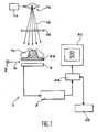
- FIG. 1 a bone osteodensitometry system 1 that is also used to make the prior radioscopy plate according to the invention.
- This system comprises an X-ray source 1a capable of sending a conical beam 1b of X-rays to the body of a patient 1c to be examined.
- This source is able to emit corresponding X-radiation respectively at two distinct levels of energy. These two levels are used to obtain two separate images of the patient.
- a removable filter ld is interposable between the source 1a and the patient 1c and serves to improve the spectral qualities of the beam.
- the system 1 also comprises a two-dimensional detector 2 which is very schematically shown in cross section on the figure 1 and intended to detect X-rays emitted by the source and having passed through the patient 1c.
- This detector 2 is parallel to a plane defined by two orthogonal directions x and y and is perpendicular to the axis of the X-ray beam.
- the patient is placed on a suitable support 2a, for example a bed, which is transparent to X-rays.
- a suitable support 2a for example a bed, which is transparent to X-rays.
- the source la (provided with the possible filter 1d) is placed above the patient resting on the support while the detector is placed below this support.
- Means not shown are provided for moving the support 2a relative to the source 1a and the detector 2, which are then fixed, or are provided to move the source 1a and the detector 2 relative to the support 2a which is then fixed, these displacements occurring parallel to the x and y directions.
- any type of two-dimensional detector for example an X-ray sensitive sensor and able to directly provide an electronic signal representative of the image acquired by the detector in the form of pixels.
- a scintillator screen can be used to receive X-rays passed through the patient and to convert these X-rays into visible light. The latter is then sent, via a mirror, to a CCD sensor provided with an objective and comprising an array of photosensitive pixels.
- FIG. 1 we also see a device 3 of the CCD controller type or the like which reads, pixel by pixel, the image representation provided by the detector and which digitizes this representation.
- the representation thus digitized is stored in a memory 3a.
- a computer 3b is provided for processing the images thus stored.
- a display device 3c for example comprising a cathode ray tube, is provided for displaying the images before or after this treatment.
- Such a system can therefore be used to implement a method according to the invention, according to which, in order to obtain good reproducibility of the measurement of bone density, a first, low-dose, radioscopic-type x-ray is used. to help position the patient in the bone densitometry system.
- this X-ray is used to retroact on the mechanics of the system (that is to say to control the mechanics of the image acquisition device so that it is positioned correctly relative to the patient or vice versa) in order to position the anatomical zone in relation to a preset reference system.
- the examination is a follow-up examination of the patient
- the X-ray is used to put the anatomical area in the same position as it was during the previous examination.
- the measurement depends on the position of the anatomical area in this beam.
- the X-ray zone 1a is provided with control means allowing it to vary the X-ray dose transmitted to the patient 1c.
- these means are adjusted so that the source sends a low dose to the patient, for example a dose equal to 1 ⁇ Sv.
- the source 1a is capable of emitting low energy X-rays and high energy X-rays.
- an X-ray beam is used which leads to a good image contrast and to a minimum dose for the examined body, with an energy for example equal to 80 keV.
- the X-ray is useful not only to position the patient before the examination but also to optimize the dose of X-rays that will be transmitted to the patient during his examination.
- the operating point of the source is adapted to the morphology (in particular to the thickness) of the patient.
- the radiophotometer is used to determine the order of magnitude of the thickness of the exposed body.
- the X-ray irradiation zone is adjusted to the morphology of the patient.
- the invention is not limited to improving a bone densitometry examination. It applies to any other radiological examination using a two-dimensional detector, for example a follow-up examination of bone fracture consolidation.
- the invention is not limited to improving the radiological examination of a patient. It can be implemented with any living or inert body, for example a table, before performing an X-ray to this table.
Abstract
Description
La présente invention concerne un procédé d'amélioration d'un examen radiologique d'une zone d'un corps ainsi qu'un dispositif pour la mise en oeuvre de ce procédé.The present invention relates to a method for improving a radiological examination of an area of a body and a device for carrying out this method.
Par « corps » on entend aussi bien un objet (par exemple un tableau ou une momie) qu'une personne ou même un animal.By "body" is meant as well an object (for example a painting or a mummy) as a person or even an animal.
L'invention s'applique à tout examen radiologique utilisant un détecteur bidimensionnel de rayons X et, en particulier, à l'ostéodensitométrie par rayonnement X bi-énergie à faisceau conique.The invention is applicable to any radiological examination using a two-dimensional X-ray detector and, in particular, cone-beam bi-energy X-ray bone densitometry.
L'invention concerne plus particulièrement le positionnement d'un patient préalablement à un tel examen radiologique ainsi que le réglage de la dose de rayons X à transmettre à ce patient lors de cet examen.The invention relates more particularly to the positioning of a patient prior to such a radiological examination and the adjustment of the dose of X-rays to be transmitted to this patient during this examination.
On rappelle que l'ostéodensitométrie par rayons X est une technique de mesure de masses et de densités osseuses à partir d'acquisitions radiographiques effectuées à une pluralité d'énergies.It is recalled that X-ray bone densitometry is a technique for measuring bone masses and densities from radiographic acquisitions made at a plurality of energies.
On utilise en général deux énergies que l'on appelle respectivement "haute énergie" et "basse énergie".In general, two energies are used which are called "high energy" and "low energy" respectively.
On distingue trois familles de systèmes d'ostéodensitométrie :
- les systèmes à pinceau dé rayonnement ("pencil beam systems") qui utilisent une source de rayons X collimatée par un trou et un monodétecteur de rayons X qui est également collimaté,
- les systèmes à faisceau en éventail ("fan beam systems") qui utilisent une source de rayons X collimatée par une fente et un détecteur linéaire de rayons X, et
- les systèmes à faisceau conique ("cone beam systems") qui utilisent une source de rayons X non collimatée et un détecteur bidimensionnel de rayons X.
- pencil beam systems using a collimated X-ray source with a hole and an X-ray monodetector which is also collimated,
- Fan beam systems using an X-ray source collimated by a slit and a linear X-ray detector, and
- Cone beam systems using a non-collimated X-ray source and a two-dimensional X-ray detector.
Les systèmes des deux premières familles nécessitent un balayage mécanique pour obtenir une image globale d'une zone anatomique alors que les systèmes de la troisième famille permettent d'établir directement une image complète.The systems of the first two families require a mechanical scan to obtain an overall image of an anatomical zone while the systems of the third family allow to directly establish a complete image.
C'est pourquoi l'invention concerne plus particulièrement les systèmes d'ostéodensitométrie par rayonnement X bi-énergie à faisceau conique.This is why the invention more particularly relates to cone beam bi-energy X-ray bone densitometry systems.
Les principes méthodologiques de l'ostéodensitométrie par rayonnement X bi-énergie et les principales solutions techniques actuellement utilisées sont connus par les deux documents suivants auxquels on se reportera :
- [1] "
Technical Principles of Dual Energy X-Ray Absorptiometry", G.M. Blake et I. Fogelman, Seminars in Nuclear Medicine, Vol XXVII, n°3, juillet 1997, pages 210 à 228 - [2] "
The Evaluation of Osteoporosis : Dual Energy X-Ray Absorptiometry and Ultrasound in Clinical Practice", Second Edition, G.M. Blake, H.W. Wahner et I. Fogelman, Martin Dunitz Editor, 1999, ISBN 1-85317-472-6
- [1] "
Technical Principles of Dual Energy X-ray Absorptiometry, GM Blake and I. Fogelman, Seminars in Nuclear Medicine, Vol XXVII, No. 3, July 1997, pages 210-228 - [2] "
The Evaluation of Osteoporosis: Dual Energy X-Ray Absorption and Ultrasound in Clinical Practice, "Second Edition, GM Blake, HW Wahner and I. Fogelman, Martin Dunitz Editor, 1999, ISBN 1-85317-472-6
On se reportera plus particulièrement aux chapitres 3, 4 et 5 du document [2] où sont décrits les principes de mesure de densités osseuses à deux énergies et les systèmes connus pour faire de telles mesures.Reference is made in particular to
On connaît aussi des systèmes d'ostéodensitométrie de zones bidimensionnelles par les documents suivants auxquels on se reportera :
- [3] brevet
US-5,150,394 - [4] Demande internationale publiée le 14 novembre 1996, n° de publication
WO 96/35372
- [3] patent
US 5150394 - [4] International application published on November 14, 1996, publication no.
WO 96/35372
On donne en outre les précisions suivantes :In addition, the following details are given:
En ce qui concerne le positionnement du patient, sur les systèmes de type "pencil beam" ou "fan beam", un premier positionnement du patient s'effectue à l'aide d'un pointeur laser qui repère la zone d'examen à partir d'observations morphologiques externes. Ensuite, le balayage avec rayonnement X débute. Si le patient est bien positionné l'examen se poursuit mais si à l'observation sur l'écran des premières lignes acquises le positionnement n'est pas bon, l'opérateur arrête tout et effectue un nouveau positionnement puis relance l'examen.With regard to the positioning of the patient, on the systems of the "pencil beam" or "fan beam" type, a first positioning of the patient is carried out using a laser pointer which marks the zone examination from external morphological observations. Then the X-ray scan starts. If the patient is well positioned the examination continues but if the observation on the screen of the first lines acquired positioning is not good, the operator stops everything and makes a new positioning and then restart the examination.
A ce sujet, on se reportera au document [2] pages 198 à 200 pour ce qui concerne la colonne vertébrale et aux pages 265 à 267 pour ce qui concerne la hanche.In this regard, reference is made to document [2] pages 198-200 for the spine and pages 265-267 for the hip.
Une étude récente a montré que, pour des systèmes du genre "pencil beam", le repositionnement avait lieu dans 50% des cas et que, pour environ 10% des examens, il fallait repositionner jusqu'à trois fois le patient. A ce sujet, on se reportera au document suivant :
- [5]
Insights, vol. 10, n°1, mars 1999, pages 10 et 11
- [5]
Insights, vol. 10, No. 1, March 1999, pages 10 and 11
Sur les systèmes du genre "cone beam" connus, utilisés pour des examens de zones périphériques, le positionnement du patient est assuré par un système mécanique d'aide au positionnement, par exemple une poignée pour l'avant-bras et une cuvette formée pour le talon.On systems of the "cone beam" type known, used for examinations of peripheral zones, the positioning of the patient is ensured by a mechanical positioning aid system, for example a handle for the forearm and a bowl formed for the heel.
En outre, on connaît déjà la possibilité d'utiliser un cliché préalable à l'examen afin d'obtenir des données de reconnaissance avant balayage (« prescan scout data ») pour « centrer » le patient, dans le domaine de la tomographie, par le brevet suivant :
- [6]
US 5457724
- [6]
US 5457724
Dans ce brevet
Le but est d'obtenir la meilleure qualité d'image reconstruite possible. En effet, comme les systèmes tomographiques sont étudiés pour que l'atténuation maximale se trouve au centre de la zone d'acquisition et comme les corrections de durcissement de spectre dépendent de la taille du champ d'acquisition, la qualité de l'image reconstruite dépend du bon centrage et de la taille du champ d'acquisition.The goal is to get the best reconstructed picture quality possible. Indeed, as the tomographic systems are studied so that the maximum attenuation is at the center of the acquisition area and as the spectrum hardening corrections depend on the size of the acquisition field, the quality of the reconstructed image depends on the proper centering and size of the acquisition field.
D'une manière générale, la présente invention a pour but d'améliorer la reproductibilité des mesures faites au cours de tout examen radiologique qui utilise un détecteur bidimensionnel.In general, the object of the present invention is to improve the reproducibility of the measurements made during any radiological examination using a two-dimensional detector.
L'invention a également pour but d'optimiser la dose de rayons X transmise au patient au cours d'un tel examen.The invention also aims to optimize the dose of X-rays transmitted to the patient during such an examination.
En particulier, la présente invention a pour but d'améliorer un examen d'ostéodensitométrie par rayonnement X bi-énergie à faisceau conique et, plus particulièrement, d'augmenter la reproductibilité des mesures de densité osseuse dans des zones anatomiques d'un patient soumis à un tel examen.In particular, the object of the present invention is to improve a cone-beam bi-energy X-ray bone densitometry examination and, more particularly, to increase the reproducibility of bone density measurements in anatomical areas of a subject patient. such an examination.
De façon précise, la présente invention a pour objet un procédé d'amélioration d'un examen radiologique d'une zone d'un corps, cet examen radiologique étant effectué au moyen d'un dispositif radiologique comprenant un détecteur bidimensionnel de rayons x, ce procédé étant caractérisé en ce que, avant l'examen radiologique, on fait un cliché bidimensionnel de radioscopie (donc avec une faible dose de rayons X), avec une seule énergie pour ces rayons X, de la zone du corps à examiner et l'on utilise ce cliché pour déterminer des premiers points caractéristiques qui définissent un référentiel de mesure, ainsi que des paramètres géométriques d'un déplacement apte à faire correspondre sensiblement ce référentiel de mesure avec un référentiel préétabli à partir de points caractéristiques équivalents correspondant aux premiers points caractéristiques .Specifically, the subject of the present invention is a method for improving a radiological examination of an area of a body, this radiological examination being carried out by means of a radiological device comprising a two-dimensional x-ray detector. characterized in that prior to the radiological examination, a two-dimensional x-ray (and thus a low dose X-ray) x-ray is taken of the area of the body to be examined with a single energy for these X-rays. this plate is used to determine first characteristic points which define a measurement frame of reference, as well as geometric parameters of a displacement able to correspond substantially this measurement frame with a pre-established frame of reference from equivalent characteristic points corresponding to the first characteristic points .
Cet examen radiologique peut être un examen d'ostéodensitométrie.This radiological examination may be a bone densitometry examination.
On précise que les premiers points caractéristiques sont en général des points précisément repérables de l'image, par exemple des points de contour, des points d'inflexion ou des points de densité extrême.It should be noted that the first characteristic points are generally precisely identifiable points of the image, for example contour points, inflection points or points of extreme density.
Selon un mode de mise en oeuvre particulier du procédé objet de l'invention, lorsque l'examen radiologique est un premier examen, le référentiel préétabli est un référentiel théorique, adapté au corps examiné.According to a particular embodiment of the method which is the subject of the invention, when the radiological examination is a first examination, the pre-established reference system is a theoretical reference, adapted to the examined body.
Selon un autre mode de mise en oeuvre particulier, lorsque l'examen radiologique suit un examen radiologique précédent, effectué au moyen du même dispositif radiologique, le référentiel préétabli est un référentiel qui est défini sur un cliché précédent à partir des points caractéristiques équivalents.According to another particular embodiment, when the radiological examination follows a previous radiological examination, carried out by means of the same radiological device, the preset reference system is a reference system which is defined on a previous image from the equivalent characteristic points.
Conformément à la présente invention, le cliché bidimensionnel est utilisable (uniquement ou en plus) pour régler la dose de rayons X à transmettre au corps lors de l'examen radiologique en adaptant le point de fonctionnement du dispositif radiologique à la morphologie du corps à examiner ou en ajustant, à la morphologie du corps à examiner, la zone à irradier par les rayons X lors de l'examen.In accordance with the present invention, the two-dimensional image is usable (only or in addition) for adjusting the dose of X-rays to be transmitted to the body during the radiological examination by adapting the operating point of the radiological device to the morphology of the body to be examined. or by adjusting, to the morphology of the body to be examined, the area to be irradiated by the X-rays during the examination.
La présente invention concerne en outre un dispositif radiologique pour la mise en oeuvre du procédé objet de l'invention, ce dispositif comprenant :
- une source de rayons X, apte à fournir un faisceau conique de rayons X à au moins une énergie,
- des moyens de variation de la dose de rayons X susceptible d'être reçue par le corps à examiner,
- un détecteur bidimensionnel de rayons X, qui est disposé parallèlement à un plan défini par deux directions orthogonales et qui est perpendiculaire à l'axe du faisceau de rayons X,
- des moyens de support du corps à examiner, ces moyens de support étant transparents aux rayons X émis par la source, disposés entre la source et le détecteur et susceptibles de subir un déplacement relatif par rapport à l'ensemble formé par la source et le détecteur, suivant les deux directions orthogonales,
- des moyens de détermination de premiers points caractéristiques sur un cliché bidimensionnel de radioscopie, ces premiers points définissant un référentiel de mesure, et
- des moyens de calcul, prévus pour déterminer les paramètres géométriques d'un déplacement apte à faire correspondre sensiblement ce référentiel de mesure avec un référentiel préétabli à partir de points caractéristiques équivalents correspondant aux premiers points caractéristiques.
- an X-ray source capable of supplying a conical beam of X-rays with at least one energy,
- means for varying the dose of X-rays that can be received by the body to be examined,
- a two-dimensional X-ray detector, which is arranged parallel to a plane defined by two orthogonal directions and which is perpendicular to the axis of the X-ray beam,
- means for supporting the body to be examined, these support means being transparent to the X-rays emitted by the source, arranged between the source and the detector and capable of being displaced relative to the assembly formed by the source and the detector , following the two orthogonal directions,
- means for determining first characteristic points on a two-dimensional radioscopy plate, these first points defining a measurement frame, and
- calculation means, provided for determining the geometric parameters of a displacement capable of substantially matching this measurement reference with a preset reference from equivalent characteristic points corresponding to the first characteristic points.
La présente invention sera mieux comprise à la lecture de la description d'exemples de réalisation donnés ci-après, à titre purement indicatif et nullement limitatif, en faisant référence aux dessins annexés sur lesquels :
- la
figure 1 est une vue schématique d'un système d'ostéodensitométrie osseuse par rayonnement X à deux énergies, à faisceau conique, qui est utilisable pour la mise en oeuvre de l'invention, et - la
figure 2 est un organigramme d'une procédure qui est utilisée dans un mode de mise en oeuvre particulier de l'invention.
- the
figure 1 is a diagrammatic view of a cone-beam two-energy X-ray bone densitometry system which can be used for carrying out the invention, and - the
figure 2 is a flowchart of a procedure that is used in a particular embodiment of the invention.
On décrit maintenant un exemple de procédé conforme à l'invention, relatif au positionnement d'un patient avant un examen d'une zone anatomique de ce dernier par ostéodensitométrie par rayonnement X bi-énergie à faisceau conique.An example of a method according to the invention relating to the positioning of a patient before an examination of an anatomical zone of the latter by cone beam bi-energy X-ray osteodensitometry is now described.
Dans cet exemple, avant de faire les acquisitions à haute et basse énergies, on fait un cliché bidimensionnel de radioscopie, à faible dose de rayons X et à une seule énergie, de la zone anatomique du patient.In this example, before making the acquisitions at high and low energies, we make a two-dimensional X-ray radiograph, at low dose of X-rays and at a single energy, of the anatomical zone of the patient.
Ensuite, d'une détection de points caractéristiques définis à partir des contours osseux sur ce cliché, on déduit les paramètres géométriques d'un déplacement permettant de faire correspondre au mieux un référentiel défini par ces points caractéristiques
- soit avec un référentiel « théorique » défini par des points équivalents, choisis à l'avance en fonction de la zone anatomique considérée, dans le cas d'un premier examen,
- soit avec un référentiel défini par des points équivalents, choisis sur un cliché bidimensionnel précédent, dans le cas d'un nième examen avec n>1.
- either with a "theoretical" reference system defined by equivalent points, chosen in advance depending on the anatomical area considered, in the case of a first examination,
- either with a referential defined by equivalent points, chosen on a previous two-dimensional plate, in the case of an nth examination with n> 1.
Dans les deux cas, on effectue un déplacement du patient par rapport au système source-détecteur que comprend le dispositif d'ostéodensitométrie, ou du système source-détecteur par rapport au patient, par commande manuelle ou automatique.In both cases, the patient is moved relative to the source-detector system that comprises the bone densitometry device, or the source-detector system relative to the patient, by manual or automatic control.
Précisons en outre que dans la présente invention il s'agit de radiologie (avec un détecteur bidimensionnel) et non pas de tomographie (avec un détecteur pour faisceau en éventail, animé d'un mouvement de rotation comme cela est décrit dans le document [6] mentionné plus haut). L'image finale est une projection bidimensionnelle et non pas une coupe reconstruite. De plus, dans l'invention, on utilise un seul cliché préalable et non pas deux clichés à 90° l'un de l'autre.It should further be pointed out that in the present invention this is radiology (with a two-dimensional detector) and not tomography (with a fan beam detector, rotated as described in document [6]). ] mentioned above). The final image is a two-dimensional projection and not a reconstructed cut. In addition, in the invention, a single pre-shot and not two shots at 90 ° from each other is used.
En outre, un but de l'exemple considéré de l'invention est la reproductibilité de la mesure de masse osseuse calculée à partir de l'image, et pas la qualité de l'image elle-même.In addition, a purpose of the example considered of the invention is the reproducibility of the measurement of bone mass calculated from the image, and not the quality of the image itself.
De plus, dans les systèmes tomographiques le recentrage du patient n'est pas automatique.Moreover, in tomographic systems the refocusing of the patient is not automatic.
Plus précisément, ce recentrage est automatique en hauteur, c'est-à-dire perpendiculairement au plan de la table qui supporte le patient ou parallèlement à l'axe du faisceau X, mais il ne l'est pas en largeur, c'est-à-dire suivant la plus petite dimension de cette table, car le déplacement latéral de la table n'est pas prévu ou n'est pas nécessaire.More precisely, this recentering is automatic in height, that is to say perpendicular to the plane of the table that supports the patient or parallel to the axis of the beam X, but it is not in width, it is -to say according to the smallest dimension of this table, because the lateral displacement of the table is not planned or is not necessary.
Rappelons que la reproductibilité est la propriété qu'a le dispositif de mesure de donner la même mesure pour différents examens sur le même patient (supposé de densité osseuse constante) et la même zone anatomique.Recall that reproducibility is the property of the measuring device to give the same measurement for different examinations on the same patient (assumed constant bone density) and the same anatomical area.
Dans le cas d'un patient dont la masse osseuse varie dans le temps, sous l'effet d'une maladie ou d'un traitement par exemple, cette propriété de reproductibilité permet de quantifier ces variations de la masse osseuse.In the case of a patient whose bone mass varies over time, under the effect of a disease or a treatment for example, this reproducibility property makes it possible to quantify these variations in bone mass.
De plus, dans la présente invention, on peut utiliser le cliché de radioscopie pour
- 1/ adapter la dose d'irradiation par réglage du flux de rayons X en modifiant le courant appliqué au tube à rayons X utilisé et/ou la tension appliquée à ce tube
- 2/ positionner automatiquement des caches permettant de limiter la zone d'irradiation, ce qui n'est pas possible en tomographie sous peine de projections tronquées.
- 1 / adjust the irradiation dose by adjusting the X-ray flux by modifying the current applied to the X-ray tube used and / or the voltage applied to this tube
- 2 / automatically set caches to limit the irradiation area, which is not possible in tomography under penalty of truncated projections.
De cette façon la dose d'irradiation reçue par le patient est minimisée.In this way the radiation dose received by the patient is minimized.
On voit sur la
Ce système comprend une source 1a de rayons X, apte à envoyer un faisceau conique 1b de rayons X vers le corps d'un patient 1c à examiner. Cette source la est apte à émettre des rayonnements X correspondant respectivement à deux niveaux distincts d'énergie. Ces deux niveaux sont utilisés pour obtenir deux images distinctes du patient.This system comprises an
Un filtre amovible ld est interposable entre la source 1a et le patient 1c et sert à améliorer les qualités spectrales du faisceau.A removable filter ld is interposable between the
Le système 1 comprend aussi un détecteur bidimensionnel 2 qui est très schématiquement représenté en coupe transversale sur la
Ce détecteur 2 est parallèle à un plan défini par deux directions orthogonales x et y et est perpendiculaire à l'axe du faisceau de rayons X.This
Le patient est placé sur un support approprié 2a, par exemple un lit, qui est transparent aux rayons X. Dans l'exemple de la
Des moyens non représentés sont prévus pour déplacer le support 2a par rapport à la source la et au détecteur 2, qui sont alors fixes, ou sont prévus pour déplacer la source 1a et le détecteur 2 par rapport au support 2a qui est alors fixe, ces déplacements ayant lieu parallèlement aux directions x et y.Means not shown are provided for moving the support 2a relative to the
Dans l'invention on peut utiliser tout type de détecteur bidimensionnel, par exemple un capteur sensible aux rayons X et apte à fournir directement un signal électronique représentatif de l'image acquise par le détecteur sous forme de pixels.In the invention can be used any type of two-dimensional detector, for example an X-ray sensitive sensor and able to directly provide an electronic signal representative of the image acquired by the detector in the form of pixels.
Au lieu de cela on peut utiliser un écran-scintillateur prévu pour recevoir les rayons X ayant traversé le patient et pour convertir ces rayons X en lumière visible. Cette dernière est alors envoyée, par l'intermédiaire d'un miroir, à un capteur CCD muni d'un objectif et comprenant un réseau de pixels photosensibles.Instead, a scintillator screen can be used to receive X-rays passed through the patient and to convert these X-rays into visible light. The latter is then sent, via a mirror, to a CCD sensor provided with an objective and comprising an array of photosensitive pixels.
Sur la
Un ordinateur 3b est prévu pour traiter les images ainsi mémorisées.A
Un dispositif d'affichage 3c, comprenant par exemple un tube à rayons cathodiques, est prévu pour afficher les images avant ou après ce traitement.A display device 3c, for example comprising a cathode ray tube, is provided for displaying the images before or after this treatment.
Un tel système est donc utilisable pour mettre en oeuvre un procédé conforme à l'invention, selon lequel, en vue d'obtenir une bonne reproductibilité de la mesure de densité osseuse, on utilise un premier cliché, à faible dose, de type radioscopie, pour aider à positionner le patient dans le système d'ostéodensitométrie.Such a system can therefore be used to implement a method according to the invention, according to which, in order to obtain good reproducibility of the measurement of bone density, a first, low-dose, radioscopic-type x-ray is used. to help position the patient in the bone densitometry system.
Revenons à l'utilisation de ce cliché de radioscopie pour le positionnement du patient.Let's go back to the use of this x-ray for the positioning of the patient.
Etant donné que, pour un système du genre "cone beam", on dispose d'un capteur bidimensionnel qui permet, en une seule acquisition, d'avoir une vision globale de la zone analysée, on propose, conformément à l'invention, de réaliser un cliché à faible dose (cliché de radioscopie) avant les acquisitions à haute et basse énergies pour aider au positionnement du patient.Since, for a system of the "cone beam" type, a two-dimensional sensor is available which makes it possible, in a single acquisition, to have a global vision of the analyzed zone, it is proposed, in accordance with the invention, to perform a low-dose radiograph (radioscopy snapshot) before acquisitions at high and low energies to help positioning the patient.
Si ce patient est soumis à son premier examen, on utilise ce cliché de radioscopie pour rétroagir sur la mécanique du système (c'est-à-dire pour commander la mécanique du dispositif d'acquisition d'images de façon qu'il se positionne correctement par rapport au patient ou inversement) afin de positionner la zone anatomique par rapport à un référentiel préétabli.If this patient is subjected to his first examination, this X-ray is used to retroact on the mechanics of the system (that is to say to control the mechanics of the image acquisition device so that it is positioned correctly relative to the patient or vice versa) in order to position the anatomical zone in relation to a preset reference system.
Si l'examen est un examen de suivi du patient, on utilise le cliché de radioscopie pour mettre la zone anatomique dans une position identique à celle qu'elle occupait lors du précédent examen.If the examination is a follow-up examination of the patient, the X-ray is used to put the anatomical area in the same position as it was during the previous examination.
Ce type de démarche permet d'augmenter sensiblement la reproductibilité des mesures effectuées au moyen de systèmes de type "cone beam".This type of approach makes it possible to substantially increase the reproducibility of measurements made by means of cone beam systems.
En raison de la conicité du faisceau de rayons X, la mesure dépend de la position de la zone anatomique dans ce faisceau.Due to the taper of the X-ray beam, the measurement depends on the position of the anatomical area in this beam.
En utilisant le cliché de radioscopie pour positionner de façon identique la zone anatomique du patient par rapport à un référentiel donné ou pour assurer la cohérence entre deux examens, on obtient une bonne reproductibilité de l'examen.By using the X-ray to identically position the anatomical area of the patient in relation to a given reference frame or to ensure consistency between two examinations, a good reproducibility of the examination is obtained.
Un exemple de mise en oeuvre pour un patient soumis à son premier examen consiste à :
- 1. réaliser un cliché à faible dose ;
- 2. extraire de cette acquisition les contours des zones osseuses, l'extraction des contours étant réalisée par un logiciel par repérage des points de gradient maximum (ou de Laplacien nul) ;
- 3. repérer des points caractéristiques (ces points caractéristiques étant par exemple des points de forte courbure, des points d'inflexion ou des points d'intersection) dans la carte de contour, par exemple identification de vertèbres ou repérage de points caractéristiques sur le col du fémur, le repérage des points caractéristiques étant réalisé par un logiciel classique de traitement d'image ;
- 4. construire la fonction de type translation qui permet de placer au mieux ces points par rapport à une position standard définie au préalable, un logiciel déterminant (par exemple par une méthode de moindres carrés) les paramètres d'une translation permettant de ramener les points caractéristiques vers une position standard ;
- 5. rétroagir sur la mécanique de positionnement pour se ramener à la position standard ;
- 6. réaliser les acquisitions.
- 1. make a low dose photograph;
- 2. extract from this acquisition the contours of the bone zones, the extraction of the contours being performed by software by locating the points of maximum gradient (or null Laplacian);
- 3. identify characteristic points (such characteristic points being, for example, points of strong curvature, inflection points or points of intersection) in the contour map, for example identification of vertebrae or identification of characteristic points on the cervix of the femur, the identification of the characteristic points being realized by a conventional software of image processing;
- 4. to construct the function of type translation which makes it possible to better place these points with respect to a standard position defined previously, a software determining (for example by a least squares method) the parameters of a translation making it possible to bring back the points features to a standard position;
- 5. retroact on the positioning mechanics to reduce to the standard position;
- 6. make the acquisitions.
Dans le cas d'un patient soumis à un examen de suivi thérapeutique, l'étape de construction de fonction 4 est remplacée par les deux étapes suivantes :
- 4.1 récupérer les positions des points caractéristiques dans les acquisitions d'un examen précédent du patient ;
- 4.2 construire la fonction de type translation qui permet de mettre au mieux en correspondance les points caractéristiques du cliché de scopie par rapport à leur position dans un examen antérieur.
- 4.1 recover the positions of the characteristic points in the acquisitions of a previous examination of the patient;
- 4.2 to construct the function of type translation which makes it possible to put at best in correspondence the characteristic points of the radiophotometer compared to their position in a previous examination.
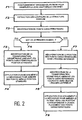
Tout ceci est précisé par l'organigramme de la
- Étape F1 : on positionne grossièrement le patient pour observer la zone anatomique d'intérêt (voir 1.)
- Étape F2 : on extrait les contours de la structure osseuse (
voir 2.) - Étape F3 : on identifie les points caractéristiques (
voir 3.) - Étape F4 : on se demande s'il s'agit du premier examen
- Si oui on va à l'étape F5 dans laquelle on identifie la transformation géométrique amenant les points caractéristiques en position standard (voir 4.) puis on va à l'étape F6 dans laquelle on applique un mouvement à la mécanique pour amener ces points vers la position standard (voir 5.)
- Si non on va à l'étape F7 dans laquelle on récupère la position des points caractéristiques dans l'examen antérieur (voir 4.1) puis on va à l'étape F8 dans laquelle on identifie la transformation géométrique amenant les points caractéristiques courants vers ceux de l'examen antérieur (voir 4.2) puis on va à l'étape F9 dans laquelle on applique un mouvement à la mécanique pour amener le patient vers une position correspondant à un bon placement des points caractéristiques (voir 5.).
- Step F1: Position the patient roughly to observe the anatomical area of interest (see 1.)
- Step F2: extract the contours of the bone structure (see 2.)
- Step F3: Identify the characteristic points (see 3.)
- Step F4: One wonders if this is the first exam
- If yes, we go to step F5 in which we identify the geometric transformation bringing the characteristic points to the standard position (see 4.) then we go to step F6 in which we apply a movement to the mechanics to bring these points to the standard position (see 5.)
- If no we go to step F7 in which we recover the position of the characteristic points in the previous examination (see 4.1) then we go to step F8 in which we identify the geometric transformation bringing the current characteristic points to those of the previous examination (see 4.2) and then we go to step F9 in which a motion is applied to the mechanics to bring the patient to a position corresponding to a good placement of the characteristic points (see 5.).
Revenons au dispositif de la
Pour faire le cliché de radioscopie on règle ces moyens 1e pour que la source envoie une faible dose au patient, par exemple une dose égale à 1 µSv.To make the x-ray image, these means are adjusted so that the source sends a low dose to the patient, for example a dose equal to 1 μSv.
De plus, la source 1a est capable d'émettre des rayons X de basse énergie et des rayons X de haute énergie.In addition, the
Pour faire le cliché de radioscopie, on utilise un faisceau de rayons X qui conduit à un bon contraste d'image et à une dose minimale pour le corps examiné, avec une énergie par exemple égale à 80 keV.To make the radioscopy, an X-ray beam is used which leads to a good image contrast and to a minimum dose for the examined body, with an energy for example equal to 80 keV.
Le cliché de radioscopie est utilisable non seulement pour positionner le patient avant son examen mais encore pour optimiser la dose de rayons X qui sera transmise au patient lors de son examen.The X-ray is useful not only to position the patient before the examination but also to optimize the dose of X-rays that will be transmitted to the patient during his examination.
Pour cette optimisation, on adapte le point de fonctionnement de la source à la morphologie (en particulier à l'épaisseur) du patient. On utilise dans ce cas le cliché de scopie pour déterminer l'ordre de grandeur de l'épaisseur du corps exposé.For this optimization, the operating point of the source is adapted to the morphology (in particular to the thickness) of the patient. In this case, the radiophotometer is used to determine the order of magnitude of the thickness of the exposed body.
En variante, pour optimiser la dose de rayons X qui sera transmise au patient lors de son examen, on ajuste la zone d'irradiation par les rayons X à la morphologie du patient. Dans ce cas, on utilise le cliché de radioscopie pour déterminer la zone osseuse et la zone de tissus autour de cette zone osseuse.Alternatively, to optimize the X-ray dose that will be transmitted to the patient during his examination, the X-ray irradiation zone is adjusted to the morphology of the patient. In this case, we use the X-ray image to determine the bone area and tissue area around this bone area.
L'invention n'est pas limitée à l'amélioration d'un examen d'ostéodensitométrie. Elle s'applique à tout autre examen radiologique utilisant un détecteur bidimensionnel, par exemple un examen de suivi de consolidation de fracture osseuse..The invention is not limited to improving a bone densitometry examination. It applies to any other radiological examination using a two-dimensional detector, for example a follow-up examination of bone fracture consolidation.
De plus, l'invention n'est pas limitée à l'amélioration de l'examen radiologique d'un patient. Elle peut être mise en oeuvre avec tout corps vivant ou inerte, par exemple un tableau, avant de faire subir une radiographie à ce tableau.In addition, the invention is not limited to improving the radiological examination of a patient. It can be implemented with any living or inert body, for example a table, before performing an X-ray to this table.
Claims (8)
- A process for improving a radiological examination of an area of a body (1c), this examination being conducted using a radiological device (1) comprising a two-dimensional X-ray detector (2), this process being characterised in that, prior to the radiological examination, a two-dimensional radioscopic image is taken, with a single energy for the X-rays used, of the area of the body to be examined and this image is used to determine first characteristic points which define a measurement reference system, and geometric parameters of a movement able to make this measurement reference system correspond approximately with a reference system pre-set from equivalent characteristic points corresponding to the first characteristic points.
- A process according to claim 1, wherein the radiological examination is an osteodensitometry examination.
- A process according to any one of claims 1 and 2, wherein the radiological examination is a first radiological examination and the pre-set reference system is a theoretical reference system, adapted to the body being examined.
- A process according to any one of claims 1 and 2, wherein the radiological examination follows a previous radiological examination, conducted using the same radiological device (1), and the pre-set reference system is a reference system, which is defined on a previous image from the equivalent characteristic points.
- A process according to any one of claims 1 to 4, wherein the image is additionally used to control the X-ray dose to be transmitted to the body (1c) during the radiological examination.
- A process according to any one of claims 1 to 5, wherein the X-ray dose to be transmitted to the body (1c) is controlled during the radiological examination, by adapting the operating point of the radiological device (1) to the morphology of the body being examined.
- A process according to any one of claims 1 to 5, wherein the X-ray dose to be transmitted to the body (1c) is controlled during the radiological examination, by setting the area to be irradiated by X-rays during the examination to the morphology of the body to be examined.
- A radiological device for implementing the process according to claim 1, this device (1) including:- an X-ray source (1a), able to supply an X-ray cone beam with at least one energy,- means (1e) of varying the X-ray dose able to be received by the body to be examined,- a two-dimensional X-ray detector (2), which is arranged parallel to a plane defined by two orthogonal directions (x, y) and which is perpendicular to the axis of the X-ray beam,- means (2a) of supporting the body to be examined, these support means being transparent to the X-rays emitted by the source, arranged between the source and the detector and able to withstand a relative movement in relation to the unit formed by the source and the detector, along the two orthogonal directions (x, y),- means of determining first characteristic points on a two-dimensional radioscopic image, these first points defining a measurement reference system, and- calculation means, provided to determine the geometric parameters of a movement able to make this measurement system correspond approximately with a reference system pre-set from equivalent characteristic points corresponding to the first characteristic points.
Applications Claiming Priority (3)
| Application Number | Priority Date | Filing Date | Title |
|---|---|---|---|
| FR9915273 | 1999-12-03 | ||
| FR9915273A FR2801978B1 (en) | 1999-12-03 | 1999-12-03 | METHOD FOR IMPROVING A RADIOLOGICAL EXAMINATION AND DEVICE FOR CARRYING OUT SAID METHOD |
| PCT/FR2000/003357 WO2001040754A2 (en) | 1999-12-03 | 2000-12-01 | Method for improving a radiological examination and device therefor |
Publications (2)
| Publication Number | Publication Date |
|---|---|
| EP1274989A2 EP1274989A2 (en) | 2003-01-15 |
| EP1274989B1 true EP1274989B1 (en) | 2010-09-01 |
Family
ID=9552867
Family Applications (1)
| Application Number | Title | Priority Date | Filing Date |
|---|---|---|---|
| EP00985379A Expired - Lifetime EP1274989B1 (en) | 1999-12-03 | 2000-12-01 | Method for improving a radiological examination and device therefor |
Country Status (6)
| Country | Link |
|---|---|
| US (1) | US20030048873A1 (en) |
| EP (1) | EP1274989B1 (en) |
| JP (1) | JP2004500173A (en) |
| DE (1) | DE60044911D1 (en) |
| FR (1) | FR2801978B1 (en) |
| WO (1) | WO2001040754A2 (en) |
Families Citing this family (12)
| Publication number | Priority date | Publication date | Assignee | Title |
|---|---|---|---|---|
| FR2825610B1 (en) | 2001-06-06 | 2004-02-20 | Diagnostic Medical Systems Dms | METHOD AND DEVICE FOR EXAMINING X-RAY OSTEODENSITOMETRY |
| US7042977B2 (en) * | 2001-09-05 | 2006-05-09 | Koninklijke Philips Electronics N.V. | Dose control in CT-images |
| US6827489B2 (en) * | 2001-11-01 | 2004-12-07 | Ge Medical Systems Global Technology Company, Llc | Low-dose exposure aided positioning (LEAP) for digital radiography |
| EP1487342A2 (en) * | 2001-12-28 | 2004-12-22 | Koninklijke Philips Electronics N.V. | Medical examination apparatus having means for performing correction of settings |
| FR2861283B1 (en) * | 2003-10-22 | 2006-01-21 | Diagnostic Medical Systems Dms | METHOD FOR DETERMINING AT LEAST ONE GEOMETRIC CHARACTERISTIC OF AN X-RAY REPERABLE PORTION LOCATED IN A PATIENT EXAMINATION AREA |
| DE102004063995A1 (en) * | 2004-10-25 | 2006-08-17 | Siemens Ag | Tomography apparatus and method for a tomography apparatus for generating multiple energy images |
| US20080159477A1 (en) * | 2006-12-29 | 2008-07-03 | General Electric Company | System and method for radiographic inspection without a-priori information of inspected object |
| DE102007016370A1 (en) * | 2007-04-03 | 2008-10-09 | Carl Zeiss Industrielle Messtechnik Gmbh | Method and a measuring arrangement for generating three-dimensional images of test objects by means of invasive radiation |
| RU2495623C1 (en) | 2012-03-11 | 2013-10-20 | Федеральное государственное бюджетное учреждение науки Институт космических исследований Российской академии наук (ИКИ РАН) | Method of dual energy dividing-subtracting mammography |
| US9105087B2 (en) * | 2012-07-20 | 2015-08-11 | Lawrence Livermore National Security, Llc | System for uncollimated digital radiography |
| JP5904548B2 (en) * | 2012-08-29 | 2016-04-13 | 富士フイルム株式会社 | Bone mineral quantitative analysis method, bone mineral quantitative analysis system, and recording medium |
| US9962134B2 (en) * | 2015-10-28 | 2018-05-08 | Medtronic Navigation, Inc. | Apparatus and method for maintaining image quality while minimizing X-ray dosage of a patient |
Family Cites Families (7)
| Publication number | Priority date | Publication date | Assignee | Title |
|---|---|---|---|---|
| US4773087A (en) * | 1986-04-14 | 1988-09-20 | University Of Rochester | Quality of shadowgraphic x-ray images |
| US6031892A (en) * | 1989-12-05 | 2000-02-29 | University Of Massachusetts Medical Center | System for quantitative radiographic imaging |
| US5150394A (en) * | 1989-12-05 | 1992-09-22 | University Of Massachusetts Medical School | Dual-energy system for quantitative radiographic imaging |
| US5838765A (en) * | 1993-11-22 | 1998-11-17 | Hologic, Inc. | Whole-body x-ray bone densitometry using a narrow-angle fan beam, including variable fan beam displacement between scan passes |
| US5457724A (en) * | 1994-06-02 | 1995-10-10 | General Electric Company | Automatic field of view and patient centering determination from prescan scout data |
| CA2163504A1 (en) * | 1994-11-25 | 1996-05-26 | Jay A. Stein | X-ray bone densitometry |
| CA2184237A1 (en) * | 1995-09-08 | 1997-03-09 | Jay A. Stein | X-ray bone densitometry |
-
1999
- 1999-12-03 FR FR9915273A patent/FR2801978B1/en not_active Expired - Fee Related
-
2000
- 2000-12-01 WO PCT/FR2000/003357 patent/WO2001040754A2/en active Application Filing
- 2000-12-01 JP JP2001542170A patent/JP2004500173A/en active Pending
- 2000-12-01 DE DE60044911T patent/DE60044911D1/en not_active Expired - Lifetime
- 2000-12-01 EP EP00985379A patent/EP1274989B1/en not_active Expired - Lifetime
- 2000-12-01 US US10/148,617 patent/US20030048873A1/en not_active Abandoned
Also Published As
| Publication number | Publication date |
|---|---|
| WO2001040754A2 (en) | 2001-06-07 |
| DE60044911D1 (en) | 2010-10-14 |
| JP2004500173A (en) | 2004-01-08 |
| WO2001040754A3 (en) | 2002-10-31 |
| US20030048873A1 (en) | 2003-03-13 |
| FR2801978B1 (en) | 2002-06-14 |
| FR2801978A1 (en) | 2001-06-08 |
| EP1274989A2 (en) | 2003-01-15 |
Similar Documents
| Publication | Publication Date | Title |
|---|---|---|
| EP1233700B1 (en) | Method for using a bone densitometry system, with dual-energy x-radiation | |
| US6751285B2 (en) | Dose management system for mammographic tomosynthesis | |
| JP5942266B2 (en) | X-ray CT apparatus and tube current determination method | |
| US6233304B1 (en) | Methods and apparatus for calcification scoring | |
| JP5274812B2 (en) | X-ray CT apparatus and image processing apparatus | |
| EP1274989B1 (en) | Method for improving a radiological examination and device therefor | |
| US6366638B1 (en) | Methods and apparatus for CT scout image processing | |
| JP3999176B2 (en) | X-ray CT apparatus, information processing method, storage medium, and program | |
| JP4675753B2 (en) | X-ray CT system | |
| EP1016375A1 (en) | Imaging system for generating high quality images | |
| EP2091437B1 (en) | Ct imaging system | |
| EP2078216B1 (en) | Imaging system for imaging an object | |
| US20080008372A1 (en) | A method and system for reducing artifacts in a tomosynthesis imaging system | |
| EP1306807A2 (en) | A tomographic image reconstruction method for tomosynthesis | |
| JP5220374B2 (en) | X-ray CT system | |
| FR2896607A1 (en) | Tomosynthesis image quality control method during imaging of patient's tumor, involves calculating in-phase resolution and slice thickness using modulation transfer function algorithm using sharpest edge coordinates in slice image | |
| KR100685561B1 (en) | X-ray ct apparatus and imaging method | |
| FR2849241A1 (en) | Medical radiographic imaging method for measuring 3D bone density distributions, in which 3D radiological data are processed in conjunction with a 3D generic model of a bone being imaged | |
| US20050152502A1 (en) | Alignment systems and methods for radiographic imaging systems | |
| US6269139B1 (en) | Methods and apparatus for pre-filtering weighting in image reconstruction | |
| US7239730B2 (en) | Method and apparatus for volume scoring calcification concentrations of a CT scan | |
| JP3466678B2 (en) | X-ray CT scanner | |
| JP4397513B2 (en) | X-ray CT system | |
| JP4582997B2 (en) | High speed computed tomography method | |
| JP7462433B2 (en) | Medical diagnostic system, medical diagnostic device, and medical information processing device |
Legal Events
| Date | Code | Title | Description |
|---|---|---|---|
| PUAI | Public reference made under article 153(3) epc to a published international application that has entered the european phase |
Free format text: ORIGINAL CODE: 0009012 |
|
| 17P | Request for examination filed |
Effective date: 20020517 |
|
| AK | Designated contracting states |
Kind code of ref document: A2 Designated state(s): AT BE CH CY DE DK ES FI FR GB GR IE IT LI LU MC NL PT SE TR |
|
| RBV | Designated contracting states (corrected) |
Designated state(s): AT BE CH DE GB IT LI |
|
| RAP1 | Party data changed (applicant data changed or rights of an application transferred) |
Owner name: COMMISSARIAT A L'ENERGIE ATOMIQUE |
|
| 17Q | First examination report despatched |
Effective date: 20080407 |
|
| GRAP | Despatch of communication of intention to grant a patent |
Free format text: ORIGINAL CODE: EPIDOSNIGR1 |
|
| RIC1 | Information provided on ipc code assigned before grant |
Ipc: G01N 23/04 20060101AFI20100303BHEP Ipc: A61B 6/00 20060101ALI20100303BHEP |
|
| RAP1 | Party data changed (applicant data changed or rights of an application transferred) |
Owner name: COMMISSARIAT A L'ENERGIE ATOMIQUE ET AUX ENERGIES |
|
| GRAS | Grant fee paid |
Free format text: ORIGINAL CODE: EPIDOSNIGR3 |
|
| GRAA | (expected) grant |
Free format text: ORIGINAL CODE: 0009210 |
|
| AK | Designated contracting states |
Kind code of ref document: B1 Designated state(s): DE GB IT |
|
| REG | Reference to a national code |
Ref country code: GB Ref legal event code: FG4D Free format text: NOT ENGLISH |
|
| REF | Corresponds to: |
Ref document number: 60044911 Country of ref document: DE Date of ref document: 20101014 Kind code of ref document: P |
|
| PG25 | Lapsed in a contracting state [announced via postgrant information from national office to epo] |
Ref country code: IT Free format text: LAPSE BECAUSE OF FAILURE TO SUBMIT A TRANSLATION OF THE DESCRIPTION OR TO PAY THE FEE WITHIN THE PRESCRIBED TIME-LIMIT Effective date: 20100901 |
|
| PLBE | No opposition filed within time limit |
Free format text: ORIGINAL CODE: 0009261 |
|
| STAA | Information on the status of an ep patent application or granted ep patent |
Free format text: STATUS: NO OPPOSITION FILED WITHIN TIME LIMIT |
|
| 26N | No opposition filed |
Effective date: 20110606 |
|
| REG | Reference to a national code |
Ref country code: DE Ref legal event code: R097 Ref document number: 60044911 Country of ref document: DE Effective date: 20110606 |
|
| PGFP | Annual fee paid to national office [announced via postgrant information from national office to epo] |
Ref country code: DE Payment date: 20121207 Year of fee payment: 13 |
|
| PGFP | Annual fee paid to national office [announced via postgrant information from national office to epo] |
Ref country code: GB Payment date: 20121219 Year of fee payment: 13 |
|
| REG | Reference to a national code |
Ref country code: DE Ref legal event code: R119 Ref document number: 60044911 Country of ref document: DE |
|
| GBPC | Gb: european patent ceased through non-payment of renewal fee |
Effective date: 20131201 |
|
| REG | Reference to a national code |
Ref country code: DE Ref legal event code: R119 Ref document number: 60044911 Country of ref document: DE Effective date: 20140701 |
|
| PG25 | Lapsed in a contracting state [announced via postgrant information from national office to epo] |
Ref country code: DE Free format text: LAPSE BECAUSE OF NON-PAYMENT OF DUE FEES Effective date: 20140701 |
|
| PG25 | Lapsed in a contracting state [announced via postgrant information from national office to epo] |
Ref country code: GB Free format text: LAPSE BECAUSE OF NON-PAYMENT OF DUE FEES Effective date: 20131201 |