EP1274613B1 - Adaptive filter model for motor vehicle sensor signals - Google Patents
Adaptive filter model for motor vehicle sensor signals Download PDFInfo
- Publication number
- EP1274613B1 EP1274613B1 EP01924048A EP01924048A EP1274613B1 EP 1274613 B1 EP1274613 B1 EP 1274613B1 EP 01924048 A EP01924048 A EP 01924048A EP 01924048 A EP01924048 A EP 01924048A EP 1274613 B1 EP1274613 B1 EP 1274613B1
- Authority
- EP
- European Patent Office
- Prior art keywords
- sensor
- physical parameter
- signal
- offset
- model
- Prior art date
- Legal status (The legal status is an assumption and is not a legal conclusion. Google has not performed a legal analysis and makes no representation as to the accuracy of the status listed.)
- Expired - Lifetime
Links
- 230000003044 adaptive effect Effects 0.000 title claims abstract description 31
- 230000001419 dependent effect Effects 0.000 claims abstract description 37
- 238000005259 measurement Methods 0.000 claims description 72
- 238000000034 method Methods 0.000 claims description 68
- 239000000446 fuel Substances 0.000 claims description 62
- 238000001914 filtration Methods 0.000 claims description 38
- 230000001133 acceleration Effects 0.000 claims description 32
- 239000011159 matrix material Substances 0.000 claims description 32
- 230000006870 function Effects 0.000 claims description 29
- 238000003745 diagnosis Methods 0.000 claims description 25
- 238000012545 processing Methods 0.000 claims description 19
- 230000000694 effects Effects 0.000 claims description 16
- 238000002347 injection Methods 0.000 claims description 13
- 239000007924 injection Substances 0.000 claims description 13
- 230000014509 gene expression Effects 0.000 claims description 11
- 238000007781 pre-processing Methods 0.000 claims description 9
- 230000008569 process Effects 0.000 claims description 9
- 238000011156 evaluation Methods 0.000 claims description 8
- 238000004422 calculation algorithm Methods 0.000 claims description 6
- 238000004364 calculation method Methods 0.000 claims description 6
- 230000007423 decrease Effects 0.000 claims description 5
- 238000004590 computer program Methods 0.000 claims description 3
- 230000036962 time dependent Effects 0.000 claims 4
- 229920000535 Tan II Polymers 0.000 description 9
- 230000010354 integration Effects 0.000 description 9
- 238000012935 Averaging Methods 0.000 description 8
- 238000010586 diagram Methods 0.000 description 7
- 230000004927 fusion Effects 0.000 description 6
- 230000005484 gravity Effects 0.000 description 6
- 238000001514 detection method Methods 0.000 description 5
- 238000013139 quantization Methods 0.000 description 5
- 230000001965 increasing effect Effects 0.000 description 4
- 230000004044 response Effects 0.000 description 4
- 238000005070 sampling Methods 0.000 description 4
- 239000000243 solution Substances 0.000 description 4
- 238000013459 approach Methods 0.000 description 3
- 230000008901 benefit Effects 0.000 description 3
- 230000000295 complement effect Effects 0.000 description 3
- 230000002708 enhancing effect Effects 0.000 description 3
- 230000010365 information processing Effects 0.000 description 3
- 238000004519 manufacturing process Methods 0.000 description 3
- 238000011161 development Methods 0.000 description 2
- 238000005516 engineering process Methods 0.000 description 2
- 230000007774 longterm Effects 0.000 description 2
- 238000012544 monitoring process Methods 0.000 description 2
- 238000005096 rolling process Methods 0.000 description 2
- 238000012360 testing method Methods 0.000 description 2
- TVZRAEYQIKYCPH-UHFFFAOYSA-N 3-(trimethylsilyl)propane-1-sulfonic acid Chemical compound C[Si](C)(C)CCCS(O)(=O)=O TVZRAEYQIKYCPH-UHFFFAOYSA-N 0.000 description 1
- 101100522042 Oryza sativa subsp. japonica PSS3 gene Proteins 0.000 description 1
- 102100039298 Phosphatidylserine synthase 1 Human genes 0.000 description 1
- 102100039300 Phosphatidylserine synthase 2 Human genes 0.000 description 1
- 101710138331 Somatostatin-1 Proteins 0.000 description 1
- 101710138332 Somatostatin-2 Proteins 0.000 description 1
- 239000000654 additive Substances 0.000 description 1
- 230000000996 additive effect Effects 0.000 description 1
- 230000008859 change Effects 0.000 description 1
- 238000004891 communication Methods 0.000 description 1
- 230000001276 controlling effect Effects 0.000 description 1
- 238000012937 correction Methods 0.000 description 1
- 230000002596 correlated effect Effects 0.000 description 1
- 230000000875 corresponding effect Effects 0.000 description 1
- 238000013500 data storage Methods 0.000 description 1
- 238000009795 derivation Methods 0.000 description 1
- 238000013461 design Methods 0.000 description 1
- 238000002474 experimental method Methods 0.000 description 1
- 238000007667 floating Methods 0.000 description 1
- 238000012417 linear regression Methods 0.000 description 1
- 230000003287 optical effect Effects 0.000 description 1
- 230000000704 physical effect Effects 0.000 description 1
- 238000004088 simulation Methods 0.000 description 1
- 239000007787 solid Substances 0.000 description 1
- 230000009897 systematic effect Effects 0.000 description 1
Images


Classifications
-
- B—PERFORMING OPERATIONS; TRANSPORTING
- B60—VEHICLES IN GENERAL
- B60T—VEHICLE BRAKE CONTROL SYSTEMS OR PARTS THEREOF; BRAKE CONTROL SYSTEMS OR PARTS THEREOF, IN GENERAL; ARRANGEMENT OF BRAKING ELEMENTS ON VEHICLES IN GENERAL; PORTABLE DEVICES FOR PREVENTING UNWANTED MOVEMENT OF VEHICLES; VEHICLE MODIFICATIONS TO FACILITATE COOLING OF BRAKES
- B60T8/00—Arrangements for adjusting wheel-braking force to meet varying vehicular or ground-surface conditions, e.g. limiting or varying distribution of braking force
- B60T8/17—Using electrical or electronic regulation means to control braking
- B60T8/1701—Braking or traction control means specially adapted for particular types of vehicles
- B60T8/1706—Braking or traction control means specially adapted for particular types of vehicles for single-track vehicles, e.g. motorcycles
-
- B—PERFORMING OPERATIONS; TRANSPORTING
- B60—VEHICLES IN GENERAL
- B60C—VEHICLE TYRES; TYRE INFLATION; TYRE CHANGING; CONNECTING VALVES TO INFLATABLE ELASTIC BODIES IN GENERAL; DEVICES OR ARRANGEMENTS RELATED TO TYRES
- B60C23/00—Devices for measuring, signalling, controlling, or distributing tyre pressure or temperature, specially adapted for mounting on vehicles; Arrangement of tyre inflating devices on vehicles, e.g. of pumps or of tanks; Tyre cooling arrangements
- B60C23/06—Signalling devices actuated by deformation of the tyre, e.g. tyre mounted deformation sensors or indirect determination of tyre deformation based on wheel speed, wheel-centre to ground distance or inclination of wheel axle
- B60C23/061—Signalling devices actuated by deformation of the tyre, e.g. tyre mounted deformation sensors or indirect determination of tyre deformation based on wheel speed, wheel-centre to ground distance or inclination of wheel axle by monitoring wheel speed
-
- B—PERFORMING OPERATIONS; TRANSPORTING
- B60—VEHICLES IN GENERAL
- B60C—VEHICLE TYRES; TYRE INFLATION; TYRE CHANGING; CONNECTING VALVES TO INFLATABLE ELASTIC BODIES IN GENERAL; DEVICES OR ARRANGEMENTS RELATED TO TYRES
- B60C23/00—Devices for measuring, signalling, controlling, or distributing tyre pressure or temperature, specially adapted for mounting on vehicles; Arrangement of tyre inflating devices on vehicles, e.g. of pumps or of tanks; Tyre cooling arrangements
- B60C23/06—Signalling devices actuated by deformation of the tyre, e.g. tyre mounted deformation sensors or indirect determination of tyre deformation based on wheel speed, wheel-centre to ground distance or inclination of wheel axle
- B60C23/061—Signalling devices actuated by deformation of the tyre, e.g. tyre mounted deformation sensors or indirect determination of tyre deformation based on wheel speed, wheel-centre to ground distance or inclination of wheel axle by monitoring wheel speed
- B60C23/062—Frequency spectrum analysis of wheel speed signals, e.g. using Fourier transformation
-
- B—PERFORMING OPERATIONS; TRANSPORTING
- B60—VEHICLES IN GENERAL
- B60T—VEHICLE BRAKE CONTROL SYSTEMS OR PARTS THEREOF; BRAKE CONTROL SYSTEMS OR PARTS THEREOF, IN GENERAL; ARRANGEMENT OF BRAKING ELEMENTS ON VEHICLES IN GENERAL; PORTABLE DEVICES FOR PREVENTING UNWANTED MOVEMENT OF VEHICLES; VEHICLE MODIFICATIONS TO FACILITATE COOLING OF BRAKES
- B60T8/00—Arrangements for adjusting wheel-braking force to meet varying vehicular or ground-surface conditions, e.g. limiting or varying distribution of braking force
- B60T8/17—Using electrical or electronic regulation means to control braking
- B60T8/172—Determining control parameters used in the regulation, e.g. by calculations involving measured or detected parameters
- B60T8/1725—Using tyre sensors, e.g. Sidewall Torsion sensors [SWT]
-
- B—PERFORMING OPERATIONS; TRANSPORTING
- B60—VEHICLES IN GENERAL
- B60T—VEHICLE BRAKE CONTROL SYSTEMS OR PARTS THEREOF; BRAKE CONTROL SYSTEMS OR PARTS THEREOF, IN GENERAL; ARRANGEMENT OF BRAKING ELEMENTS ON VEHICLES IN GENERAL; PORTABLE DEVICES FOR PREVENTING UNWANTED MOVEMENT OF VEHICLES; VEHICLE MODIFICATIONS TO FACILITATE COOLING OF BRAKES
- B60T8/00—Arrangements for adjusting wheel-braking force to meet varying vehicular or ground-surface conditions, e.g. limiting or varying distribution of braking force
- B60T8/17—Using electrical or electronic regulation means to control braking
- B60T8/1755—Brake regulation specially adapted to control the stability of the vehicle, e.g. taking into account yaw rate or transverse acceleration in a curve
-
- B—PERFORMING OPERATIONS; TRANSPORTING
- B60—VEHICLES IN GENERAL
- B60T—VEHICLE BRAKE CONTROL SYSTEMS OR PARTS THEREOF; BRAKE CONTROL SYSTEMS OR PARTS THEREOF, IN GENERAL; ARRANGEMENT OF BRAKING ELEMENTS ON VEHICLES IN GENERAL; PORTABLE DEVICES FOR PREVENTING UNWANTED MOVEMENT OF VEHICLES; VEHICLE MODIFICATIONS TO FACILITATE COOLING OF BRAKES
- B60T2210/00—Detection or estimation of road or environment conditions; Detection or estimation of road shapes
- B60T2210/10—Detection or estimation of road conditions
- B60T2210/13—Aquaplaning, hydroplaning
-
- B—PERFORMING OPERATIONS; TRANSPORTING
- B60—VEHICLES IN GENERAL
- B60T—VEHICLE BRAKE CONTROL SYSTEMS OR PARTS THEREOF; BRAKE CONTROL SYSTEMS OR PARTS THEREOF, IN GENERAL; ARRANGEMENT OF BRAKING ELEMENTS ON VEHICLES IN GENERAL; PORTABLE DEVICES FOR PREVENTING UNWANTED MOVEMENT OF VEHICLES; VEHICLE MODIFICATIONS TO FACILITATE COOLING OF BRAKES
- B60T2240/00—Monitoring, detecting wheel/tyre behaviour; counteracting thereof
- B60T2240/03—Tyre sensors
-
- B—PERFORMING OPERATIONS; TRANSPORTING
- B60—VEHICLES IN GENERAL
- B60T—VEHICLE BRAKE CONTROL SYSTEMS OR PARTS THEREOF; BRAKE CONTROL SYSTEMS OR PARTS THEREOF, IN GENERAL; ARRANGEMENT OF BRAKING ELEMENTS ON VEHICLES IN GENERAL; PORTABLE DEVICES FOR PREVENTING UNWANTED MOVEMENT OF VEHICLES; VEHICLE MODIFICATIONS TO FACILITATE COOLING OF BRAKES
- B60T2250/00—Monitoring, detecting, estimating vehicle conditions
- B60T2250/06—Sensor zero-point adjustment; Offset compensation
Definitions
- the invention achieves an increase of performance in existing sensors by enhancing the sensor signal. Furthermore, new information is found by combining and processing sensor signals and associate the result with other physical or operating parameters than those directly related with the sensors.
- Yaw rate and absolute velocity estimation is perhaps most appropriate for cars and trucks.
- the determination of roll angle is important for an ABS and spin control, since less tire forcess can be utilised in cornering.
- headlight control can be implemented dependent on roll angle.
- Roll angle estimation is furthermore crucial for roll-over detection, used in some airbag control units. Similarly to yaw rate estimation in cars, this can be done by using wheel speed and a lateral-vertical accelerometer pair.
- Such a roll angle estimation carried out without using a roll gyro is an example of a virtual sensor, where only indirect measurements are used to compute the physical quantity.
- This type of sensor usually suffers from medium-frequency disturbances in the noise component el(t), which is normally handled with a very slow low-pass filter.
- el(t) the noise component
- low-frequency accuracy in the time constant of one re-fuelling is good.
- the offset depends inter alia on manufacturing variations and temperature.
- the inventive method comprises the following steps:
- the described mathematical expressions are employed for example in a virtual sensor as shown in Fig 6 , taking as an input a selection of yaw signal from gyro, lateral acceleration signal ay, vertical acceleration signal az and wheel angular velocity signal ⁇ f.
- the sensor signals are preferably preprocessed by being low pass filtered in stage 602. sampled in stage 604, low pass filtered in stage 606 and data reduced in stage 608.
- the angular velocity signal is preferably also rescaled in stage 610.
- the thus preprocessed sensor signals are the input into an adaptive filter 612 based on a model in accordance with the previous description.
- the output of the filter are values or signals for a roll angle, sensor offsets and yaw rate.
- This type of sensor usually suffers from medium frequency disturbances in the noise component e 1 which is normally handled with a very slow low-pass filter.
- low-frequency accuracy in the time constant of one re-fuelling is good.
- the offset depends inter alia on manufacturing variations and temperature.
Landscapes
- Engineering & Computer Science (AREA)
- Mechanical Engineering (AREA)
- Transportation (AREA)
- Physics & Mathematics (AREA)
- Mathematical Physics (AREA)
- Control Of Driving Devices And Active Controlling Of Vehicle (AREA)
- Steering Control In Accordance With Driving Conditions (AREA)
- Control Of Electric Motors In General (AREA)
- Testing Or Calibration Of Command Recording Devices (AREA)
- Gyroscopes (AREA)
- Feedback Control In General (AREA)
- Length Measuring Devices With Unspecified Measuring Means (AREA)
- Vehicle Body Suspensions (AREA)
Abstract
Description
- The present invention relates generally to a system for integrating sensors of physical parameters, and more specifically to a system for sensor fusion in a wheeled vehicle.
- In the current development within vehicle technology there is an increasing interest in enhancing the safety and the manoeuvrability of vehicles by means of a number of support systems. Examples of well-known support systems in wheeled vehicles are antilock brake systems (ABS), traction control systems and tire pressure estimation systems. This kind of systems are usually provided with more or less complex sensors such as gyroscopes and wheel speed sensors to gather information about physical parameters affecting the vehicle.
- Along with the development of technology there is an increasing demand for safety enhancing equipment in standard cars, something which is not always compatible with an acceptable price level on this segment of cars. There is therefore a need for developing cost efficient sensor equipment while improving the usability of the sensor signals.
- An important parameter for automatic support systems, such as dynamic stability traction control (DSTC), is the course direction of the vehicle. The course is usually expressed in terms of the yaw angle, which is the direction of motion relating to a longitudinal axis of the vehicle, and the yaw rate, which is the angular velocity of the rotation of the vehicle around its centre of gravity in the horizontal plane.
- In a simple approach, the yaw rate is independently calculated from different sensors in the vehicle, such as a gyro sensor, ABS sensors, an accelerometer sensor or a steering wheel angle sensor, and thus resulting in different values of the yaw rate. These values have been compared and voting has been used to decide which information to use.
- Sensor signals generally comprise a parameter value and an offset from the true parameter value. The offsets are due to imperfect knowledge of the parameters and their dependencies, and the offsets vary in time due to for example temperature changes and wear. An accurate estimation of the offsets is crucial to the ability of accurately estimating the parameter value itself. The traditional way to improve sensor signals is to use a low pass filter in order to get rid of high frequency variations, and sometimes an offset can be estimated using long term averaging. Averaging has its shortcomings. For example in yaw rate estimation, a systematic circular driving will give the same effect as an offset. Furthermore, if two sensor signals measuring the same physical parameter are averaged, an improved estimate of the parameter may be obtained but it does not help in estimating the offset.
- The perhaps most well known support parameter for the driver of a wheeled vehicle is the velocity. The vehicle velocity may be estimated based on the angular velocity of the driven wheel, however with an inaccuracy due to wheel slip, wheel skid or varying tire diameter. The standard approach to compute velocity is to use the wheel speed signals from the wheel speed sensors and possibly averaging over left and right wheels. To avoid errors due to wheel slip the non-driven wheels are preferably used. This approach has however, shortcomings during braking when the wheels are locked and during wheel spin on 4 wheel-driven (WD) vehicles. For 4 WD vehicles an additional problem is that even during normal driving there will be a small positive velocity offset due to the wheel slip.
- An example of the state of the art sensor utilisation is shown in
US Patent No. 5.878.357 to Sivashankar et al . This piece of prior art is directed to vehicle yaw rate estimation by a combination of a kinematic yaw rate estimation and a dynamic yaw rate estimation using accelerometers. A kinematic yaw rate estimate is weighted with a vehicle lateral acceleration at the centre of gravity, and steering angle and vehicle forward speed are incorporated into a Kalman filter for achieving a dynamic vehicle yaw rate estimate. This system uses relatively low-cost sensor components but is sensitive to difficult driving cases and errors in the wheel radii, for example due to varying tire pressure. Another drawback is that it requires wiring through the whole car in order to collect sensor signals from an accelerometer at the front as well as the rear of the car. - Another example of prior art directed to yaw rate measuring is found in
US Patent No. 5,274,576 to Williams . This prior art uses a solid state rate gyrometer, the accuracy of which is known to depend on the ambient temperature. Measuring means provides a velocity signal, a steering angle and a lateral acceleration signal, which are all used in a correction means in order to remove bias errors from the output signal of the gyrometer. It is noted that this system is basically a low pass filter only compensating for long term bias errors. - The
US Patent No. 5,860,480 to Jayaraman et al shows a method for determining pitch and ground speed of an earth moving machine, and is directed to estimating certain operating parameters. This prior art seeks to overcome problems of noise and bias in sensor signals. Using a sensor measurement model, a machine process model and Kalman filter update equations the pitch, the pitch rate and ground speed are estimated as a function of sensed pitch and ground speed signals. - The European Patent No.
EP 0 595 681 A1 - Document
DE 4 123 053 discloses a method for estimating parameters of motion of a vehicle, for example lateral velocity, yaw velocity, floating angle, slip angles and lateral forces. This is achieved by the use of two adaptive equivalent Kalman filters. - Document
WO 9 810 297 - The general problem to be solved by the present invention is to improve the usability of signals from existing sensors measuring a first physical parameter.
- Aspects of the problem are:
- to improve the accuracy of such sensors signals;
- to achieve a virtual sensor signal for a second physical parameter dependent on said first physical parameter;
- to use and combine sensor information from different available sources in order to achieve improved parameter estimates or virtual sensor signals;
- to accurately estimate and eliminate offsets from parameter values in the sensor signals.
- A further and more specific aspect of the problem is to provide an improved computation of a course indication in the shape of yaw angle and yaw rate for a wheeled vehicle.
- Yet another specific aspect of the problem is to provide an improved estimation of the velocity of a wheeled vehicle.
- A further aspect of the problem is to compute the actual fuel level and instantaneous fuel consumption for any engine, where offset distorted measurements of the same quantities are available.
- Yet another specific aspect is to compute the roll angle of a vehicle, in particular for motorcycles.
- The object of the invention is defined by the subject matter of independent claims 1, 45, 47 and 49.
- The object of the invention is achieved by processing a plurality of sensor signals in an adaptive or recursive filter thereby producing an optimized estimation of a first physical parameter detected by said sensors. In accordance with the invention, a particularly advantageous recursive filter is provided by a Kalman filter. In the invention, the Kalman filter is used as a framework for processing related sensor signals and estimating their respective offsets. These related sensor signals do not necessarily have to measure the same physical parameter, and in embodiments of the invention they usually represent different parameters. Besides giving an accurate estimate of the offset, the Kalman filter also has the advantageous possibility of attenuating noise.
- The invention achieves an increase of performance in existing sensors by enhancing the sensor signal. Furthermore, new information is found by combining and processing sensor signals and associate the result with other physical or operating parameters than those directly related with the sensors.
- According to an aspect of the invention, the accuracy of sensor signals are highly improved by combining the signals of a plurality of existing or simple add-on sensors in the recursive filtering means.
- According to another aspect of the invention, a virtual sensor signal for a second physical parameter dependent on one or more first physical parameters is generated by combining sensors of different type sensing different first physical parameters by means of combined sensor signals from real sensors. In other terms, all available information from sensors in the vehicle is systematically fused in a recursive filter, preferably a Kalman filter.
- When applying the sensor fusion in accordance with the invention in computing a yaw rate value, at least two sensor signals are input into a Kalman filter in order to minimize the error in an estimate signal representing the yaw rate value. In a preferred embodiment, these sensors signals are a yaw rate signal taken from a gyro, wheel speed signals taken from an ABS equipment, possibly also a lateral yaw rate signal computed from a lateral accelerometer and steering wheel angle signals. An accurate yaw rate value can for example be applied in lateral slip computation, which is used in stability systems and friction estimation. Furthermore, there are effects of the second order, for example an estimation of absolute tire radii and consequently also absolute velocity. Moreover, the filtering process provides computations of differences in tire radii as well as signals for diagnosis of faults in the respective sensors. The diagnosis signals may be used to warn the driver or be stored in a fault report to be used in connection with service of the vehicle.
- An accurate estimation of vehicle velocity is achieved in accordance with an embodiment of the invention wherein wheel speed sensor signals are combined with an accelerometer signal and processed in a filtering process in accordance with the above description. In accordance with the invention, the velocity is accurately computed even during braking and when the wheels are locked. For a 4 WD vehicle or when non-driven wheel speed signals are not available, the invention compensates for wheel slip and in addition to velocity also gives acceleration information. Other parameters that are derived in embodiments of the invention are slip-offset e.g. usable for tire pressure estimation in 4 WD vehicles, slip-slope e.g. usable for tire friction estimation in 2 WD and 4 WD vehicles, acceleration offset and the wheel velocity in the drive direction. These embodiments as well as detection of aquaplaning are examples of application of theory for the longitudinal stiffness of tires.
- The slip of a vehicle wheel is a function of the momentum applied on a wheel, wherein the slip-offset is a constant term of the function and the slip-slope is the constant of proportionality between the applied momentum and the slip.
- There are different further aspects that are relevant to different kinds of vehicles. Yaw rate and absolute velocity estimation is perhaps most appropriate for cars and trucks. For motorcycles, the determination of roll angle is important for an ABS and spin control, since less tire forcess can be utilised in cornering. Also, headlight control can be implemented dependent on roll angle. Roll angle estimation is furthermore crucial for roll-over
detection, used in some airbag control units. Similarly to yaw rate estimation in cars, this can be done by using wheel speed and a lateral-vertical accelerometer pair. Such a roll angle estimation carried out without using a roll gyro is an example of a virtual sensor, where only indirect measurements are used to compute the physical quantity. It is here crucial to find and compensate for the accelerometer offsets, which is conveniently achieved with the aid of the invention.As a further support, a roll gyro and longitudinal accelerometer can be incorporated in the algorithm. Another example of great practical importance is to detect aqua-planing quickly, for cars, trucks and motorcycles. - Other aspects and embodiments of the invention are disclosed in the description of detailed embdoiments and the claims.
- The invention will now be further described by means of exemplifying embodiments in conjunction with the accompanying drawings, in which:
-
Fig 1A - 1D show schematic block diagrams embodiments of the invention; -
Fig 2A shows schematically an embodiment of the invention applied in yaw rate computation; -
Fig 2B shows the invention applied in velocity computation; -
Fig 2C shows the invention applied in fuel consumption computation; -
Fig 2D shows the invention applied in slip slope computation; -
Fig 3A shows an embodiment of an autocalibrating sensor in accordance with the invention; -
Fig 3B shows a schematic drawing which defines the geometric relations of a four wheeled vehicle; and -
Fig 4 shows a plot diagram of an estimated offset in accordance with the invention from an experimental test drive; -
Fig 5A and 5B show coordinate systems and sensor configuration in a motorcycle; -
Fig 6 shows an embodiment of a virtual sensor for a roll angle indicator in a motorcycle; -
Fig 7 shows wheel geometry; and -
Fig 8 shows a schematic block diagram of a virtual sensor for an aqua planning detector in accordance with an embodiment of the invention. - The invention is based on the following general idea of sensor fusion, which is here described by way of example in terms of matrix algebra. This example relates to two sensors detecting the same physical parameter, but in different embodiments of the invention signals from sensors detecting different parameters may be integrated.
- Two different sensors sensing the same varying physical parameter give separate measurements yi(t) of a the parameter x, where each measurement has an offset bi with an offset scaling ci(t) according to a known function of time. The measurements can be expressed algebraically as the equations:


These two equations have three unknowns and is therefore insoluble, and the offsets cannot be directly eliminated. - When two measurements y1(1),y2(1) and y1(2),y2(2) are available, there are two more equations and only one more unknown, i.e. four equations and four unknowns. Thus, the offsets and the variable parameter values x(1),x(2) can be solved under the condition that there is no linear dependency in data. In this example, the linear independency condition is:

- If, for example, c1 is constant and c2(t) is the velocity vx(t), linear independency occurs when the velocity has changed between two measurements. This leads to observability and identifiability. Typically, measurements would be carried out by sensors delivering a continuous or discrete sensor output signal which is sampled into a digital data processing system. The samples are collected in a per se known manner with a predetermined sampling frequency, thus giving rise to a corresponding number of observations in the shape of equations to process.
- In practice there is a measurement noise added to each of the observations. In order to eliminate the noise, certain embodiments of the invention are devised to collect a number of observation samples large enough to constitute an overdetermined equation system and to compute the least square solution.
- The invention also makes use of the a priori knowledge that the parameter variable x is a correlated sequence that cannot change arbitrarily fast between two samples. This property of the parameter variable x is used in a recursive filter, preferably a Kalman filter, into which the sampled observations input.
- The invention is generally implemented in a digital or analogue sensor control system of a car. Such a system typically includes wired, optical or wireless data communication links for communicating the output of a sensor to a control unit. The control unit is provided with a data processor, which in preferred embodiments is a digital processor having a data storage memory and signal input and output ports. The digital processor is programmed with a computer program product being provided with means for directing the processor to perform the functions and the steps of the inventive method. In an analogue implementation of the inventive concept, the control unit is provided with circuit elements specifically devised to perform the functions of the inventive method.
-
Fig 1 shows a schematic diagram showing the functional blocks of the invention. Sensors or sensor signal suppliers 102,104,106,108, capable of generating sensor signals S1,S2,S3,S4 dependent on or representing a respective physical parameter, are coupled to asensor integration unit 110. For example, in one embodiment the ABS is used assensor signal supplier 102, thesensor 104 is a gyro, thesensor 106 is one or more accelerometers and the engine is a sensor signal supplier 108.The sensor integration unit comprises a recursive filter, preferably a Kalman filter, devised to provide an estimate of a predetermined physical parameter, and outputs a physical parameter signal PSS 1 to a first sensor signal processing unit, more specifically a self calibrating sensor, here called a virtual sensorsignal processing unit 112. The virtual sensorsignal processing unit 112 is devised to compute one or more virtual sensor signals VSS based on the physical parameter signal PSS1. The computed virtual sensor signal is for example the yaw rate Ψ(dot), the velocity vx of the vehicle and the fuel consumption d Vfuel/dt. The virtual sensor signal is then communicated to one ormore control units 118. for example devised for controlling an ABS, a traction control system, a dynamic stability traction control system (DSTC) or an adaptive cruise control system (ACC). A roll angle detector is an example of both a virtual sensor when realised without a roll gyro and a self-calibrating sensor realised in conjunction with a roll gyro. The roll angle estimate can be used in roll-over detection in cars and for improving ABS and anti-spin control and enabling headlight control in motorcycles.With the help of these virtual signals, aqua-planing can be detected with high reliability. - In the embodiment shown in
Fig 1 , thesensor integration unit 110 outputs a second physical parameter signal PSS2 to a second sensor signal processing unit, which perhaps more properly constitutes a virtual sensor but in this figure is called an intelligentsensor processing unit 114, devised to compute a complementary, intelligently computed sensor signal ISS used in a driverinformation processing unit 120. Such intelligent sensor signals may for example represent friction and tire conditions such as pressure or vibration. Thesensor integration unit 110 is also devised to deliver a third physical sensor signal PSS3 communicated to third sensor signal processing unit in the shape of a diagnosissignal processing unit 116, which outputs a diagnose signal DSS to the driverinformation processing unit 120. The driver information processing unit in its turn outputs signals for example indicating friction conditions, tire pressure or faults in predetermined car components. Furthermore, a fourth physical parameter signal PSS4 may be delivered by the sensor integration unit to a fourth sensor signal processing unit, namely a vehicle controlsignal processing unit 117 devised to generate and deliver suitable vehicle control signals VCS for example to vehicle operating apparatuses such as engine or brake control. -
Fig 1B shows schematically the structure of a self-calibrating sensor in accordance with one embodiment of the invention, as explained in connection with equations 1-3. Two sensor signals y1 and y2 representing a physical parameter are input into anadaptive filter 122 deviced to estimate in accordance with a predeteremined model and deliver as as output signal offsets b1(hat) and b2 (hat). The sensor signals y1,y2 are also input into an observability evaluation functionality together with possibleexternal info 128, the evaluation unit being deviced to output an enablesignal 125 to theadaptive filter 122 when the conditions allow observability. The offset signal b1(hat) is joined with the sensor signal y1 in asubstraction stage 126 where the value of the offset b1 (hat) is substracted from the sensor signal value to produce a value or a quantity of a parameter X. -
Fig 1C shows a general flow chart for the steps in a sensor fusion system, such as a self calibrating sensor in accordance with the invention, comprising the following steps: - Initializing the system;
- Receiving as an input the next measurement or sample from the sensors;
- Checking observability of parameter;
- If observability is OK then updating offset estimates;
- After uppdating of offset estimates or if observability is not OK then compensate sensor signals with the offset output from the adaptive filter.
-
Fig 1D shows schematically an example of a virtual sensor comprising anadaptive filter 136 based on a predetermined model integrating model parameters values representing first and second different physical or operating parameters. First and second sensor signals y1 and y2 representing said first and second different parameters are input into thefilter 136 and into anobservability evaluation unit 138. Theobservability evaluation unit 138 checks whether observability for the physical parameters is fulfilled and if so outputs an enablesignal 139 to theadaptive filter 136. In enabled condition, theadaptive filter 136 calculates and outputs an estimate of a physical quantity or value X(hat) together with an estimate of offset values b1(hat) and b2(hat). The physical quantity X(hat) is the value of a physical model X as a function f(y1,y2) dependent on the sensor signals y1 and y2. - One embodiment of the invention is directed to achieve an adaptive high precision yaw rate sensor by combining sensor signals from a gyro and from wheel angular velocity sensors of an ABS and by computing an accurate yaw rate by means of an adaptive filter. Specific embodiments may comprise further sensor signals, for example the signals from a lateral accelerometer, in order to further enhance the performance of the sensor.
Fig 2 shows schematically a yaw ratesignal ψ̇ gyro 202 from a gyro and wheel angular speed signals 204 from an ABS being input in afilter 206 in accordance with the invention. Thefilter 206 outputs a computed yaw angle ψ,yaw rate ψ̇ 208 as well as yaw rate offset values. -
Fig 3A shows shematically a more detailed autocalibrating sensor for determining yaw rate, wherein a yaw rate signal ψ̇ from a gyro and angular velocity signals ωi for the wheels are is input into anadaptive filter 301 as well as into anobservability evaluation unit 302. Theevaluation unit 302 generates and inputs into the adaptive filter an enablesignal 304 when the sensed parameters are observable. Theadaptive filter 301 generates as an output a yaw rate offset value δgyro representing the offset of the yaw rate signal from the gyro. The yaw rate ψ̇ and the offset value δgyro are joined in asummation unit 303 producing a ψ̇ -improved as an output. -
Fig 3B shows a simple drawing of a four wheeled vehicle, which drawing defines the geometric relations for the wheel velocities during cornering used to compute yaw rate from wheel speed signals. More specifically, the relations are used to compute the curve radius, where R is defined as the distance to the centre of the rear wheel axle from a predetermined point O, L is the lateral distance between the wheels on one axle and B is the longitudinal distance between front and rear wheel axle. The wheels are in this example denoted as rl for rear left, rr for rear right, fl for front left and fr for front right. A coordinate system indicating the x,y, and z-directions is also drawn inFig 3B . For the sake of clarity of the drawing, the coordinate system is drawn in front of the vehicle, but is in reality typically positioned in the centre of gravity of the vehicle. - For the sake of simplicity of the explanation of the invention, this exemplifying embodiment is based on relations assuming there is no lateral movement. In the relations:

ψ̇ is the yaw rate from a gyro;
vx is the velocity of the vehicle in the x-direction;
ay is the acceleration in the γ-direction. The curve radius is computed according to the following relation, where R is defined as the distance to the center of the rear wheel axle,
- The angular wheel velocities ω for each of the respective wheels are received from an ABS and the inverse R -1 of R is solved in order to avoid numerical problems in certain driving cases, e.g. driving straight ahead. This results in

where the wheel radius is denoted r. - The wheel radii ratio is subject to an offset:

- The influence of the offset on the denominator is negligible, so according to embodiments of the invention the following expression is used for inverse curve radius:

wherein the computable quantity
is used for the inverse curve radius. - Finally, the velocity at the center of the rear wheel axle is

where r denotes the nominal wheel radius. - In a practical implementation of this embodiment, the sensor measurements are: y 1(t) from a yaw rate sensor, i.e. gyro signal;


It should be noted that when a lateral accelerometer is used, this is preferrably supported by a vertical accelerometer to compensate for non-horizontal movements of the vehicle. - All these sensor measurements are subject to an offset and measurement noise given by the relations:

where δABS is an offset that depends on relative tire radius between left and right wheels. - As has been described above, the measurement signals are treated in a filter. A general filter description is given in the following section. In one embodiment, the offset is estimated by means of the least squares method. So, eliminating the yaw rate from the first two measurements yields a linear regression in the two offsets:

where:
Using also an accelerometer, the regression quantities are
- The least squares estimate is computed by

- The important question of identifiability, that is, under what conditions are the offsets possible to estimate, is answered by studying the rank of the matrix to be inverted in the LS solution. For the accelerometer sensor, the matrix is given by:

In short, this matrix has full rank if and only if the velocity changes during the time horizon. Furthermore, the more variation, the better estimate. Similarly, the offsets are identifiable from yaw rate and ABS sensors if the velocity or the curve radius changes anytime. In accordance with the invention, the offsets are estimated adaptively by recursive least squares (RLS) algorithm, least mean square (LMS) or a Kalman filter. - In real time implementations of the invention, the Kalman filter is preferred and improves the performance over RLS in the following way:
- Firstly, a model for the variation of the true yaw rate can be incorporated in the Kalman filter. For instance, the yaw rate may be limited to 5Hz maximum frequency variation.
- Secondly, different time-variations of the sensor offsets can be used. For instance, temperature can influence the gyro offset variation, a cold start can make the filter forget more of the gyro offset than the ABS offset
- The Kalman filter is completely specified by a state space equation of the form

where the covariance matrices of v(t) and e(t) are denoted Q and R, respectively.
The unknown quantities in the state vector x(t) are estimated by a recursion
where the filter gain K(t;A,B,C,Q,R) is given by the Kalman filter equations.Thus, the problem when designing an implementation is to setup the state space model. - An exemplifying embodiment uses the state vector:

and a continuous time state space model is:

It is here assumed that there is an unknown input v(t) that affects the yaw acceleration, which is a common model for motion models, basically motivated by Newton's law F = ma.
A discrete time state space model: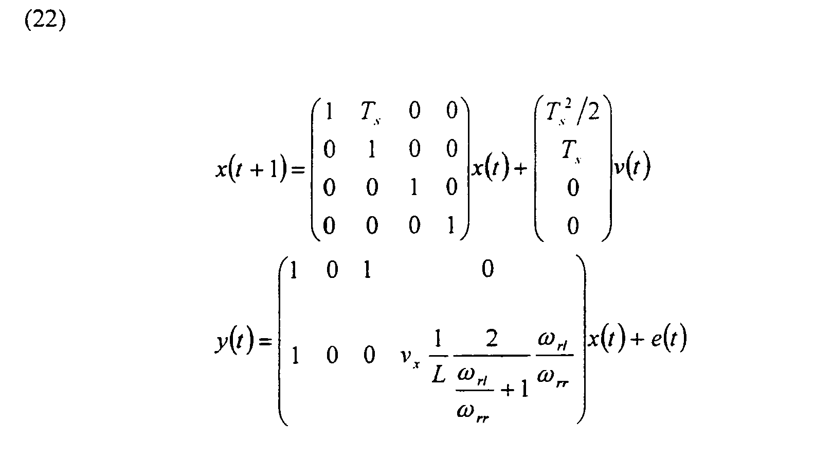
is derived and is used by the Kalman filter. - Embodiments of the invention integrating information from wheel speed signals and gyro are thus capable to give accurate yaw angle and yaw rate measurements where the gyro offset and relative tire radii differences are estimated and compensated for. As an alternative, or further support, to ABS, one or several lateral accelerometers can be used to support the yaw rate sensor with a further yaw rate dependent sensor signal.
- Simulations and experiments show that the accuracy in yaw rate, not regarding the offsets, is better than using any of the sensor types separately.
Fig 4 shows a plotted diagram 401 of a Kalman filter estimated gyro offset 403 compared with a very exact offline adjusted offset 402, the diagram having the time in seconds on the x-axis and gyro offset in rad/s on the y-axis. The diagram offig 4 is a registration from an experimental test drive and shows that the Kalman filter estimation after a short transitional period converges with the offline adjusted offset within a margin of a few percentages of offset scale units. - A further advantage with the inventive concept is that the relative difference in wheel radii on non-driven right and left wheels can be very accurately estimated, which is advantageously used for tire pressure indication. In different embodiments the Kalman filter is used as a combined parameter estimator for the offset as well as a filter for yaw rate. In an alternative embodiment, an adaptive filter is used to estimate the offset parameters. A further effect of the invention is that it gives support for diagnosis of faults in gyro and accelerometer.
- In a stepwise description of the embodiment for yaw rate estimation, the inventive method comprises the following steps:
- (1) Collecting measurements from
- (a) a yaw rate gyro
- (b) ABS Sensors
- (c) possibly a lateral accelerometer
- (d) possibly wheel steering angle sensor
- (2) Preprocessing and filtering of raw sensordata
- 1 Scaling of sensor inputs to physical constants
yawrate = nom.scale_facto_gyro * rawinputgyro - nom.offset_gyro. - 2 Low-pass filtering of yaw rate to reduce quantization and noise error effects for instance averaging over a few samples.
- 3 Rotational synchronization of cog stamps to avoid cog deformity error effects i.e. calculate wheel angular velocity by using a full revolution of the wheel.
- 4 Similar treatment of sensors (c) and (d) to reduce known error effects for instance low-pass filtering.
- 5 Performing simple diagnosis on sensors to take care of sensor built-in diagnosis functions for instance sensors using a zero level voltage to indicate internal failure.
- 1 Scaling of sensor inputs to physical constants
- (3) Calculating filter inputs and parameters in error model
- 1 Calculate the inverse curve radii estimate from front axle wheelage
- 2 Calculate the inverse curve radii estimate from rear axle wheelage (with indices changed to wfl and wfr)
- 3 Calculate the vehicle velocity estimate from ABS sensors
- 4 Calculate the yaw rate estimate from front and rear wheelage
- 5 Calculate the wheel radii offset error propagation function for rear axle
- 6 Calculate the wheel radii offset error propagation function for front axle
- (4) Examine data quality by given norms to produce statistical matrices for Kalman Filtering, for instance:
- 1 Low velocity increases noise and other errors in yaw rate from ABS sensors estimated
if (velocity_estimate < LOW_LEVEL)
Increase values in Kalman measurement covariance
matrix R - 2 Standstill car assures yaw rate to be exactly zero
if (velocity_estimate == ABSOLUTE_ZERO)
Decrease values in Kalman measurement covariance
matrix R
- 1 Low velocity increases noise and other errors in yaw rate from ABS sensors estimated
- (5) Applying the Kalman Filter equations
- 1 Time update of Kalman Filter
xhat = F*xhat;
Phat = F*Phat*F'+ G*Q*G'; - 2 Measurement update of Kalman Filter
e = y - H*xhat;
xhat = xhat + K*e;
Phat - Phat - K*H*Phat';
Phat = 0.5*(Phat + Phat');
Where xhat is the current state estimate and Phat is the current Kalman error covariance matrix, y is current measurement, H is measurement matrix, F is state space model update matrix and G is noise update matrix. - 1 Time update of Kalman Filter
- (6) Output of yaw rate and offset estimates
- I Provide a fast yaw rate which is the current measured low-pass filtered yaw rate minus the estimated offset to be used by for instance time-critical control systems.
- 2 Provide a filtered yaw rate which is the current yaw rate state estimate of the Kalman Filter to be used by for instance navigation systems.
- 3 Provide relative wheel radii between left and right wheels on rear and front wheelage to be used for instance by tire pressure estimation systems.
- 4 Provide the rate gyro offset estimate to be used in diagnosis functions.
- One embodiment of the invention is concerned with applying the invention for velocity computation, or more generally expressed longitudinal motion computation based on standard sensors of a vehicle. In accordance with the invention, a sensor signal from an accelerometer ax is integrated with a wheel angular velocity signal ω for example from an ABS in a sensor
signal integration unit 218. The sensor signal integration unit comprises, as explained above, a filtering process, and outputs a computedvelocity signal vx 220 and a computedacceleration signal ax 222. As described above, an accelerometer sensing acceleration in the horizontal plane is preferably combined with a vertical accelerometer for compensation for vertical motion. Since this embodiment uses an accelerometer as a complement to the wheel speed signals, the velocity can be computed after locking the wheels when braking. - The basic equations upon which the computation is based are similar to those described above in connection with the yaw rate computation. Therefore, only the sensor signals to be fused and their characteristics are shown here. Wheel angular speed signals ω are received from an ABS and are transformed to a scaled velocities at selected positions in the car. The first sensor signal from the ABS is described by:

wherein
y 1 is the angular velocity of a driving wheel;
vx is the absolute velocity of the wheel;
r is the wheel radius;
k is the slip-slope;
δ is the slip offset; and
µ is the wheel momentum.
The offset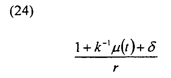
is here multiplicative, which means that the relations are non linear and the extended Kalman filter must be used. The sensor is accurate at medium frequencies at a time scale where the friction and tire characteristics k, δ are unchanged.
The second sensor signal from an accelerometer in longitudinal direction ax is described by:
Summing up to time t gives:
- The offset scalings (1 and t) are linearly independent if the traction force = µ(t) does not increase linearly in time, so the offsets b2, k, δ are observable. In this embodiment, offset and drift free velocity is computed from driven wheel speed and accelerometer with non-negligible offset for instance to be used in 4WD vehicles when free-rolling wheels are not available. It also has a fast response to longitudinal velocity changes during skid, i.e. spin or brake. Furthermore, the embodiment is advantageously used for diagnosis of accelerometer. The system estimates the slip slope in a friction model which is also used to estimate tire-road friction.
- In a stepwise description of the embodiment for velocity computation, the inventive method comprises the following steps:
- (1) Collection of measurements from
- (a) a longitudinal accelerometer
- (b) ABS Sensors
- (c) possibly a yaw rate gyro
- (2) Preprocessing and filtering of raw sensordata
- 1 Scaling of sensor inputs to physical constants
- 2 Low-pass filtering of longitudinal acceleration measurement to reduce quantization and noise error effects for instance averaging over a few samples.
- 3 Rotational synchronization of cog stamps to avoid cog deformity error effects i.e. calculate wheel angular velocity by using a full revolution of the wheel.
- 4 Perform simple diagnosis on sensors to take care of sensor built-in diagnosis functions for instance sensors using a zero level voltage to indicate internal failure.
- (3) Calculation of filter inputs and parameters in error model
- 1 Calculate the vehicle velocity estimate from ABS sensors (Page 8 - Eq 11)
- 2 Calculate the parameters in the error model (Page 12 - Eq 23)
- 3 Calculate current matrices for the extended Kalman Filter (F, G, H, Q)
- (4) Examine data quality by given norms to produce statistical matrices for Kalman Filtering, for instance:
- 1 Low velocity increases noise in velocity measurement from ABS sensors
if (velocity_estimate < LOW_LEVEL)
Increase values in Kalman measurement covariance
matrix R - 2 Standstill car assures velocity to be exactly zero
if (velocity_estimate = ABSOLUTE_ZERO)
Decrease values in Kalman measurement covariance
matrix R
- 1 Low velocity increases noise in velocity measurement from ABS sensors
- (5) Applying the Kalman Filter equations for the extended Kalman Filter
- 1 Time update of Kalman Filter
xhat = F*xhat;
Phat = F*Phat*F'+ G*Q*G'; - 2 Measurement update of Kalman Filter
e = y - H*xhat;
xhat - xhat + K*e;
Phat = Phat - K*H*Phat';
Phat - 0.5*(Phat + Phat');
Where xhat is the current state estimate and Phat is the current Kalman error covariance matrix, y is current measurement, H is measurement matrix, F is state space model update matrix and G is noise update matrix. - 1 Time update of Kalman Filter
- (6) Output of velocity and offset estimates
- 1 Provide a velocity estimate for control systems and MMI.
- 2 Provide wheel slips for 4WD vehicles
- 3 Provide the accelerometer offset estimate to be used in diagnosis functions.
- An embodiment of the invention is directed to computation of fuel level and fuel consumption. This embodiment is schematically shown in
Fig 2C and takes as an input afuel volume signal 224 from the tank meter of the vehicle and a fuel injection signal 226 from the engine. The basic equations are again similar to those described above, however the sensor signals are modelled according to the following equations. - Firstly, the tank level measurement is:

This type of sensor usually suffers from medium-frequency disturbances in the noise component el(t), which is normally handled with a very slow low-pass filter. On the other hand, low-frequency accuracy in the time constant of one re-fuelling is good. The offset depends inter alia on manufacturing variations and temperature. - Secondly, a fuel injection signal tq or the like is transformed to a momentary fuel consumption signal described as:

This sensor is very good at high frequencies, basically since it measures derivatives. - Summing up to time t gives:

The offset scalings 1 and t are linearly independent and therefore the offsets are observable. - This in effect virtual sensor has the advantages of fast response after re-fuelling, is an offset free monitor of momentary as well as average values of fuel consumption, and is suitable to use for diagnosis of faults in fuel pipes and engine efficiency.
- In a stepwise description of the embodiment for fuel consumption, the inventive method comprises the following steps:
- (1) Collection of measurements from
- (a) a tank level measurement device
- (b) fuel injection signal
- (2) Preprocessing and filtering of raw sensordata
- I Scaling of sensor inputs to physical constants
- 2 Low-pass filtering of fuel injection measurement to reduce quantization and noise error effects for instance averaging over a few samples.
- 3 Perform simple diagnosis on sensors to take care of sensor built-in diagnosis functions for instance sensors using a zero level voltage to indicate internal failure.
- (3) Calculation of filter inputs and parameters in error model
- I Calculate the tank fuel level estimate from fuel level sensor
- 2 Calculate the fuel consumption from fuel injection signal
- (4) Examine data quality by given norms to produce statistical matrices for Kalman Filtering, for instance:
- I High load on engine gives unreliable consumption results, increase part of R
- (5) Applying the Kalman Filter equations
- 1 Time update of Kalman Filter


- 2 Measurement update of Kalman Filter


- 1 Time update of Kalman Filter
- (6) Output of fuel level fuel consumption and offset estimates
- I Provide fuel level for MMI systems.
- - 2 Provide fuel comsumption level for control systems and MMI systems
- One embodiment of the invention is applied in velocity computation, or more generally expressed longitudinal motion computation based on standard sensors of a vehicle. In accordance with a variety of this embodiment, a sensor signal from an accelerometer ax is integrated with a wheel angular velocity signal ω (for example from an ABS unit) in a sensor signal integration unit. The sensor signal integration unit comprises, as explained above, a filtering process, and outputs a computed velocity signal vx and a computed acceleration signal ax . As described above, an accelerometer sensing acceleration in the horizontal plane is preferably combined with a vertical accelerometer for compensation for vertical motion. Since this embodiment uses an accelerometer as a complement to the wheel speed signals, the velocity can be computed also after locking the wheels when braking.
- Wheel angular speed signals ω are received from an ABS and are transformed to scaled velocities at selected positions in the car. The first sensor signal from the ABS is described by

where y 1 is the angular velocity of a driving wheel, vx is the absolute velocity of the wheel, r is the wheel radius, k is the longitudinal stiffness, δ is the slip offset, µ is the normalized traction force, and e 1 is measurement noise.
The offset
(31) is here multiplicative, which means that the relations are non-linear and a non-linear observer or the extended Kalman filter must be used. The sensor is accurate at medium frequencies, at a time scale where the friction and tire characteristics, k and δ, are unchanged.
The second sensor signal from an accelerometer in longitudinal direction ax is described by
Summing up this equation to time t gives
The offset scalings (1 and t) are linearly independent if the normalized traction force µ(t) does not increase linearly in time, so the offsets b2 , k, δ are observable.
In this embodiment, offset and drift free velocity is computed from driven wheel speed and accelerometer with non-negligible offset for instance to be used in 4WD vehicles when free-rolling wheels are not available. It also has a fast response to longitudinal velocity changes during skid, i.e. spin or brake. Furthermore, the embodiment is advantageously used for diagnosis of the accelerometer. The system estimates the slip slope in a friction model which is also used to estimate tire-road friction. - In a stepwise description of the embodiment for velocity computation, the inventive method comprises the following steps:
- (1) Collection of measurements from:
- (a) a longitudinal accelerometer
- (b) ABS Sensors
- (c) possibly a yaw rate gyro
- (2) Preprocessing and filtering of raw sensordata:
- Scaling of sensor inputs to physical constants
- Low-pass filtering of longitudinal acceleration measurement to reduce quantization and noise error effects for instance averaging over a few samples.
- Rotational synchronization of cog stamps to avoid cog deformity error effects, i.e.. calculate wheel angular velocity by using a full revolution of the wheel.
- Perform simple diagnosis on sensors to take care of sensor built-in diagnosis functions for instance sensors using a zero level voltage to indicate internal failure.
- (3) Calculation of filter inputs and parameters in error model:
- Calculate the vehicle velocity estimate from ABS sensors
- Calculate the parameters in the error model
- Calculate current matrices for the extended Kalman Filter (F, G, H, Q)
- (4) Examine data quality by given norms to produce statistical matrices for Kalman Filtering, for instance:
- Low velocity increases noise in velocity measurement from ABS sensors
if (velocity_estimate < LOW_LEVEL)
Increase values in Kalman measurement covariance matrix R - Standstill car assures velocity to be exactly zero
if (velocity_estimate == ABSOLUTE_ZERO)
Decrease values in Kalman measurement covariance matrix R
- Low velocity increases noise in velocity measurement from ABS sensors
- (5) Applying the Kalman filter equations for the extended Kalman filter:
- (a) Time update

- (b) Measurement update

Where x̂k is the current state estimate, Pk is the current state error covariance matrix, and yk is current measurement. The state space matrices Fk, Gk and Hk are obtained by linearizing the non-linear state space model around the current state estimate x̂k . The results and uses of velocity and offset estimates in accordance with this embodiment are for example to provide a velocity estimate for control systems and MMI (man machine interface), to provide wheel slip indications or estimates for 4WD vehicles, and to provide an accelerometer offset estimate to be used in diagnosis functions.
- (a) Time update
- An embodiment of the invention being applicable for a virtual sensor as well as for an autocalibrating sensor is directed to achieve a roll angle indicator.By way of example, the described embodiment uses a lateral and a vertical accelerometer, a yaw rate gyro and a velocity estimate. The measurement from the lateral accelerometer is denoted ay and from the vertical accelerometer az. The required velocity is in this example provided by the ABS by rescaling the angular velocity with the wheel radius.
- A common problem with accelerometers is a temperature dependent sensor offset. This invention provides an alternative to the costly solution of calibrating all sensors during production also entailing that an additional temperature sensor is required on each motorcycle. An embodiment of the invention is adapted to estimate and compensate for the sensor offsets automatically during driving.
- Accelerometers and gyros typically deliver a continuous time signal. In order to use this signal in a discrete time system this signal must be sampled using a suitable sampling rate. Alias effects are avoided by using an anti alias filter (LP-filter) before the sampling. Outliers deteriorates the performance of the system and are removed before the sensor fusion stage. The sensor fusion is performed using an adaptive filter, preferrably a Kalman filter.
Models describing the accelerometers are derived using mechanical engineeringe. The general expressions for an ideal lateral and an ideal vertical accelerometer moving in a field of gravity are:
with notation for a motorcycle in accordance with the illustration of coordinate systems inFig 5A , the sensor configuration inFig 5B and according to the following.Symbol Meaning u Longitudinal velocity u̇ Longitudinal acceleration v Lateral velocity v̇ ateral acceleration w Vertical velocity ẇ Vertical acceleration Φ Roll angle ϕ̇ Angular velocity around local axle x̂ ϕ̈ Angular acceleration around local axle x̂ Θ Pitch angle θ̇ Angular velocity around local axle ŷ θ̈ Angular acceleration around local axle ŷ ψ̇ Angular velocity around local axle ẑ ψ̈ Angular acceleration around local axle ẑ x Position of sensor in coordinate axle x̂ y Position of sensor in coordinate axle ŷ z Position of sensor in coordinate axle ẑ g Gravity (g ≈ 9.81 [m/s 2])
The sensor models are simplified to
If Θ is assumed to be constant equal to zero are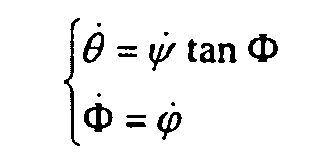
It is now obvious that the local roll rate ϕ̇ is equal to the global roll rate Φ̇ and also that θ̇ can be eliminated from the accelerometer models.

The first term in the expressions, uψ̇ or uψ̇ tan Φ, is important for modelling high velocity turns. The increased normal force on the motorcycle from the ground is explained by this term. The second term depends on the location of the sensor in ẑ and the third is the influence from gravity.Unfortunately there are two allowed solutions to these two expressions. In order to improve the system is one more interpretation of the lateral measurement required. This interpretation is made using necessary conditions to achieve state of equilibrium in steady state turning. - Using Newtons equations is the following expression derived

Symbol Meaning m Total mass, driver + motorcycle + load lf Moment of inertia front wheel lr Moment of inertia rear wheel rl Wheel radius front wheel rr Whel radius rear wheel 
Parameter dependent on MC geometry 
Parameter dependent on MC geometry z r Distance ground to center of mass Θ Tilt Φ(i Roll angle to the CoM driver + MC 
which describes the physical properties of the particular type of motorcycle. Assuming Φ(j = Φ results in
Assume constant pitch angle Θ̇ = 0 and use θ̇ = ψ̇ tan Φ
Inserting this expression in the earlier derived expression for the lateral accelerometer yields
where the new variables α1 and α2 are constants describing the geometry of the motorcycle but are not equal to

- There are now one model for the vertical and two models for the lateral accelerometer available.


- A rate gyro model follows from that the rate gyro is attached in the longitudinal direction x̂ and measures ideally the roll angle derivative or gyro = ϕ̇
There are now one sensor model for the ideal vertical acceleromter, two models for the ideal lateral acceleromter and one model for the ideal rate gyro. An improved model is achieved if the model is extended with additive sensor offsets:


where the notation is as presented earlier andNotation Meaning δy Sensor offset lateral accelerometer δz Sensor offset vertical accelerometer δ gyro Sensor offset gyro - The adaptive filter is in this embodiment implemented by means of an extended kalman filter. A continuous time state space model is derived and is then transformed to a discrete time state space model using per se known theory from linear systems and sampled systems. The continuous time state space model for the system is


The state vector x consists of seven elements x = (x 1 x 2 x 3 x 4 x 5 x 6 x 7) T , wherein: - x 1 =ϕ = Rotation around x̂
- x 2 = ϕ̇ = Angular velocity around x̂
- x 3 = ϕ̈ = Angular acceleration around x̂
- x 4 = ψ̇ = Angular velocity around ẑ
- x 5 = δ y = Accelerometer offset lateral accelerometer
- x 6 = δz = Accelerometer offset vertical accelerometer
- x 7 =δgyro = Gyro offset.

- Writing the discrete time signal model z = h(x), the extended Kalman filter is applied as follows.

Here f, g and h are nonlinear functions of the states xk . Define the matrices F, G and H according to:

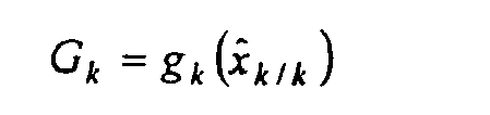
The linearized signal model be written as

where

and

- The extended Kalman filter equations are then





Initialisation is provided by:
- The necessary matrices for the roll angle estimation problem using two accelerometers the velocity of the motorcycle and an extended kalmanfilter are:


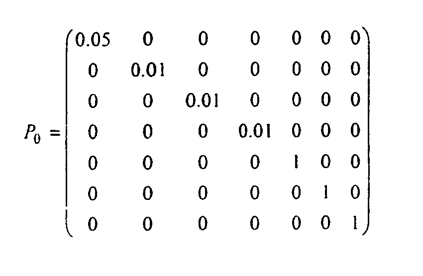
- All that remains in order to run the algorithm is the initialization.
x 0 is chosen to suitable values and the matrix P 0 reflects the uncertainty ofx 0 - One choice is
- The described mathematical expressions are employed for example in a virtual sensor as shown in
Fig 6 , taking as an input a selection of yaw signal from gyro, lateral acceleration signal ay, vertical acceleration signal az and wheel angular velocity signal ωf. The sensor signals are preferably preprocessed by being low pass filtered instage 602. sampled instage 604, low pass filtered instage 606 and data reduced instage 608. The angular velocity signal is preferably also rescaled instage 610. The thus preprocessed sensor signals are the input into anadaptive filter 612 based on a model in accordance with the previous description. The output of the filter are values or signals for a roll angle, sensor offsets and yaw rate. - One embodiment of the invention is directed to computation of fuel level and fuel consumption. This embodiment takes as an input a fuel volume signal from the tank meter of the vehicle, and a fuel injection signal from the engine. The basic equations are again similar to those described in earlier sections, however the sensor signals are modelled according to the following equations.
- Firstly, the tank level measurement is:

This type of sensor usually suffers from medium frequency disturbances in the noise component e 1 which is normally handled with a very slow low-pass filter. On the other hand, low-frequency accuracy in the time constant of one re-fuelling is good. The offset depends inter alia on manufacturing variations and temperature. - Secondly, a fuel injection signal tq or the like is transformed to a momentary fuel consumption signal described as

This sensor is very good at high frequencies, basically since it measures derivatives. Summing up y2 to time t gives:
The offset scalings 1 and t are linearly independent and therefore the offsets are observable. - This in effect virtual sensor has the advantages of fast response after re-fuelling, is an offset free monitor of momentary as well as average values of fuel consumption, and is suitable to use for diagnosis of faults in fuel pipes and engine efficiency.
- In a stepwise description of the embodiment for fuel consumption, the inventive method comprises the following steps:
- 1. Collection of measurements from:
- (a) a tank level measurement device;
- (b) a fuel injection signal
- 2. Preprocessing and filtering of raw sensor data:
- (a) Scaling of sensor inputs to physical constants
- (b) Low-pass filtering of fuel injection measurement to reduce quantization and noise error effects for instance averaging over a few samples.
- (c) Perform simple diagnosis on sensors to take care of sensor built-in diagnosis functions for instance sensors using a zero level voltage to indicate internal failure.
- 3. Calculation of filter inputs and parameters in error model:
- (a) Calculate the tank fuel level estimate from fuel level sensor
- (b) Calculate the fuel consumption from fuel injection signal
- 4. Examine data quality by given norms to produce statistical matrices for Kalman Filtering, for instance:
- (a) High load on engine gives unreliable consumption results, increase part of R
- 5. Applying the Kalman Filter equations
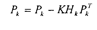
- (a) Time update of Kalman Filter


- (b) Measurement update of Kalman Filter



- (a) Time update of Kalman Filter
- 6. Output of fuel level fuel consumption and offset estimates
- (a) Provide fuel level for MMI systems.
- (b) Provide fuel comsumption level for control systems and MMI systems
- One embodiment of the invention is directed to automatic aqua planning detection (APD) based on the following principles.The measured signals and computed quantities that are utilized by the virtual sensor APD are summarized shown in
Fig 7 and the following table.Symbol Description ω d Angular velocity, driven wheel [rad/s] ω n Angular velocity, non-driven wheel [rad/s] rd Wheel radius, driven wheel [m] rn Wheel radius, non-driven wheel [m] Te Engine torque [Nm] i Gearing ratio from engine to driven wheels [-] N Normal force at driven wheel [N] s Wheel slip [-] µ Normalized traction force [-] -
Fig 8 shows a schematic view of the functional components in a variety of this embodiment, viz vehicle signals 802 are input into a precomputation or preprocessingstage 804. The precomputed output is the filtered in an adaptivefiltering process stage 806 in accordance with the inventive concept producing output parameter signals that are subject to evaluation or used in a diagnosis instage 808. - The virtual sensor APD detects aqua planning by monitoring the longitudinal stiffness k, which during normal driving conditions can be modeled as

where
is the normalized traction force and
is the wheel slip. Here N is the tire normal force that depends on the mass, the vehicle geometry and the vehicle state (such as the current velocity and acceleration/retardation). In case of aqua planning, the lack of friction between the tire and the road gives rise to an increased wheel slip s if the traction force µ is maintained. Therefore, it is possible to detect aqua planning by monitoring sudden decreases in the estimated slope parameter k. In practice it is necessary to take into account that the wheel radii rd and rn are unknown. By introducing δ as the relative difference in wheel radii, i.e.,
and approximating the wheel slip as
and approximating the wheel slip as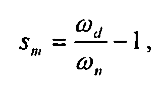
obtains the model
The parameters in this model, 1/k and δ, are estimated from measured slip Sm and traction force µ using an adaptive filter, such as a recursive least squares algorithm or a Kalman filter and the state space model

where x1 = (1/k δ) T , H1 = (µ1 1) T , and wr and er are process and measurement noise respectively. - The invention has been described by means of exemplifying embodiments for different applications and it should be appreciated that several designs are possible within the inventive concept and as defined in the claims.


Where T is the sampling time. Derivation of F and G from A and B is straightforward according to the theory for sampled systems.

Claims (50)
- A method for determining a physical parameter value (x) of a wheeled vehicle, comprising the steps of:- receiving a first sensor signal (y1) that is dependent on a first physical parameter kind affecting a condition of the wheeled vehicle;- receiving a second sensor signal (y2) that is dependent on a second physical parameter kind affecting a condition of the wheeled vehicle;- recursively filtering said first and second sensor signal (y1,y2) by means of an adaptive filter based on a predetermined model of the condition of the wheeled vehicle, said model being dependent on said first physical parameter kind, on said second physical parameter kind and on the offset error (b1) for said first sensor signal,- estimating the values of offset errors of said first and second sensor signals by means of said filter, said model further being dependent on the offset error (b2) for said second sensor signal and the dependence (c1,c2) of said first and second offset errors being incorporated in the model;- determining in said filtering first type information about said physical parameter (x) by means of said first and second sensor signals (y1,y2) and by means of a plurality of predetermined relations between measured values (y1(t),y2(t)) of said physical parameter (x) from said first and second sensor signals, said physical parameter value (x(t)) and said first and second offset errors (c1(t)b1,c2(t)b2) of said first and second sensor signals (y1,y2);- determining in said filtering second type information about said physical parameter (x) by means of a number of time dependent measurements (y1 (t),y2(t)) of said physical parameter (x) represented by said first and second sensor signals and by means of said predetermined relations;- calculating, dependent on said first type information and second type information, a physical parameter value signal (X) such that said first and second offset errors are compensated for and eliminated.
- The method of the preceding claim, wherein the model is based on relations between measured values (y(t)) of said physical parameter (x(t)) and offsets (b1,b2) for said first and second sensor signals corresponding to the algebraic expression

 - where y1(t) is a measurement of said physical parameter x(t) detected by means of a first sensor and represented by said first sensor signal having said first offset error b1 and a first offset scaling c1(t) according to a predetermined function of time; and- where y2(t) is a measurement of said physical parameter x(t) detected by means of a second sensor and represented by said second sensor signal having said second offset error b2 and a second offset scaling c2(t) according to a predetermined function of time.
 - The method of claim 1, wherein the model is based on relations between measured values (yi(t)) of said physical parameter (x(t)) and offsets (bi) for a number i of sensor signals corresponding to the algebraic expression
 - where yi(t) is a measurement of said physical parameter x(t) detected by means of a sensor number i and represented by a sensor signal having an offset error bi and an offset scaling ci(t) according to a predetermined function of time.
 - The method of any of the preceding claims, further comprising the steps of the steps of:- evaluating the observability of said physical parameter;- updating offset estimates if a predetermined observability criterion is met.
- The method of any of the preceding claims, further comprising the steps of receiving a third sensor signal dependent on a third physical parameter kind affecting the condition of the wheeled vehicle and recursively filtering said third sensor signal together with said first and second sensor signals by means of said adaptive filter, which is based on a model that also is dependent on said third physical parameter and on the offset error for said third sensor signal.
- The method of any of the preceding claims, wherein said filter is based on a model that also is dependent on measurement noise in the sensor signals respectively and further comprises the step of calculating and eliminating the measurement noise of the calculated physical parameter value signal.
- The method of any of the preceding claims, wherein said filter is based on a recursive least means square algorithm (RLS).
- The method of any of the preceding claims, wherein said filter is based on a least means square algorithm (LMS).
- The method of any of the preceding claims, wherein said filter is based on a Kalman filter.
- The method of the preceding claim, wherein said Kalman filter is specified by means of a state space equation of the form:


where the covariance matrices of v(t) and e(t) are denoted Q and R, respectively, and wherein the unknown quantities in a state vector x(t) are estimated by a recursion:
where the filter gain K(t;A,B,C,Q,R) is given by predetermined Kalman filter equations. - The method of the preceding claim, wherein said Kalman filter incorporates a model for the variation of the true physical parameter value of the wheeled vehicle.
- The method of any of the preceding claims, further comprising the steps of:- examining the data quality according to predetermined rules;- producing statistical matrices for Kalman filtering dependent on said rules.
- The method of the preceding claim, wherein said rules are:- if (velocity estimate <LOW_LEVEL)⇒
then increase values in Kalman measurement covariance matrix R
and- if (velocity estimate =ABSOLUTE_ZERO) ⇒
then decrease values in Kalman measurement covariance matrix R. - The method according to any of the preceding claims, further comprising applying Kalman filter equations by means of the steps of:- time updating the Kalman filter

 - measurement updating the Kalman filterwhere xhat is the current state estimate and Phat is the current Kalman error covariance matrix, y is the current measurement, H is measurement matrix, F is state space model update matrix and G is noise update matrix.


- The method of any of the preceding claims, further comprising pre-processing raw sensor data by:- scaling sample sensor signals to physical constants according to the model that physical constant is set equal to a nominal scale factor multiplied with the raw sensor data value minus a nominal sensor offset.
- The method of the preceding claim, further comprising pre-processing raw sensor data by low-pass filtering sensor signal values in order to reduce quantisation errors and noise errors.
- The method of any of the preceding claims, further comprising pre-processing raw sensor data by rotationally synchronising clock stamps from cog-wheels by calculating wheel angular velocity to avoid cog deformity error effects.
- The method of any of the preceding claims, further comprising the step of providing an offset estimate to said sensor signals for use in diagnosis functions.
- The method of any of the preceding claims, further being adapted for determining the yaw rate of said wheeled vehicle,- wherein said first sensor signal is a yaw rate signal from a yaw rate gyro mounted in the wheeled vehicle;- wherein said second sensor signals are angular wheel velocity signals from angular wheel velocity sensors mounted in the wheeled vehicle for sensing the angular velocity of the wheels respectively;- wherein said model is dependent on said yaw rate signal, said angular wheel velocity signals, the offset error for the yaw rate signal and the offset errors for the angular wheel velocity signals; and- wherein said delivered physical parameter value signal is a calculated yaw angle and a calculated yaw rate signal.
- The method of claim 19, wherein said third sensor signal is an acceleration signal from an accelerometer mounted in the wheeled vehicle for sensing a lateral acceleration and wherein said adaptive filter is based on a model that is also dependent on said lateral acceleration signal and on the offset error for said acceleration signal.
- The method of claim 19, further comprising the steps of calculating and eliminating measurement noise from the calculated yaw rate signal.
- The method of claim 19, wherein said Kalman filter incorporates a model for the variation of the true yaw rate of the wheeled vehicle.
- The method of claim 19, further comprising the steps of calculating offset errors for said angular wheel velocity signals and calculating the relative difference in wheel radii between right and left wheels dependent on said offset errors for wheel velocity signals.
- The method of claim 19, further comprising calculating filter input signals and parameters in an error model by the steps of:- calculating an inverse curve radius estimate from front axle wheels of the wheeled vehicle;- calculating an inverse curve radius estimate from rear axle wheels of the wheeled vehicle;- calculating vehicle velocity estimate from the angular wheel velocity sensors;- calculating yaw rate estimates from front and rear wheels;- calculating an error propagation function for wheel radius offsets for a rear axle of the wheeled vehicle;- calculating an error propagation function for wheel radius offsets for a front axle of the wheeled vehicle.
- The method of claim 19, further comprising the step of providing a fast yaw rate which is the current measured low-pass filtered yaw rate minus the estimated offset for use in time critical control systems.
- The method of claim 19, further comprising the step of providing a filtered yaw rate which is the current yaw rate state estimate of the Kalman filter.
- The method of claim 19, further comprising the step of providing relative wheel radii between left and right wheels on rear and front wheelage to be used in a tire pressure estimation system.
- The method of claim 19, further comprising the step of providing a yaw rate gyro offset estimate to be used in a diagnosis function.
- The method of any of the claims 1-15, further adapted for determining longitudinal movement of said wheeled vehicle,- wherein said first sensor signal is an acceleration signal from an accelerometer mounted in the wheeled vehicle;- wherein said second sensor signals are angular wheel velocity signals from angular wheel velocity sensors mounted in the wheeled vehicle for sensing the angular velocity of the respective wheels;- wherein said model is dependent on said acceleration signal, said angular wheeled velocity signals, the offset error for the acceleration signal and the offset errors for the angular wheel velocity signals; and- wherein said delivered physical parameter value signal is a calculated longitudinal velocity signal and a calculated longitudinal acceleration signal.
- The method of claim 29, wherein the adaptive filter is an extended Kalman filter.
- The method of claim 29, wherein said third sensor signal is a yaw rate signal for the wheeled vehicle and wherein said adaptive filter is based on a model that is dependent also on said yaw rate signal and on the offset error for said yaw rate sensor signal.
- The method of claim 29, further comprising calculation of filter input signals and parameters in an error model by the steps of:- calculating a vehicle velocity estimate from angular vehicle velocity sensors;- calculating the parameters in the error model;- calculating current matrices for an extended Kalman filter (F,G,H,Q).
- The method of claim 29, further comprising the step of providing a velocity estimate for a control system and an MMI (Man Machine Interface).
- The method of claim 29, further comprising the step of providing wheel slip values.
- The method of claim 29, further comprising the step of providing an accelerometer offset estimate for use in a diagnosis function.
- The method of any of the claims 1-15, further being adapted for determining fuel level and fuel consumption of said wheeled vehicle:- wherein said first sensor signal is a fuel volume signal from a tank meter of the wheeled vehicle;- wherein said second sensor signal is a fuel injection sensor signal from the engine of the wheeled vehicle;- wherein in said model is dependent on said fuel volume signal, said fuel injection signal, the offset error for the fuel volume signal and the offset error for the fuel offset signal; and- wherein said delivered physical parameter value signal is a calculated fuel level and a calculated fuel consumption signal.
- The method of claim 26, further comprising calculation of filter input signals and parameters in an error model by the steps of:- calculating a fuel level estimate from the fuel level sensor signal;- calculating the fuel consumption from the fuel injection signal.
- The method of any of the preceding claims, further comprising the steps of:- examining the data quality according to the predetermined rules;- using statistical matrices for Kalman filtering dependent on said rules.
- The method of claim 38, wherein said rules for examining the data quality is:- if there is a high load on the engine then increase part of values in the Kalman measurement covariance matrix R.
- The method of claim 36, further comprising the step of providing the fuel level estimate for an MMI system (Man Machine Interface).
- The method of claim 36, further comprising the step of providing a fuel consumption estimate for a control system and an MMI system (Man Machine Interface).
- The method of claim 1, further comprising the step of using external information in the observability evaluation.
- The method of claim 1, further comprising the steps of:- initializing the sensor and filter system;- receiving as an input the next measurement or sample of said sensor signals;- checking the observability of said physical parameter;- if observability is met, then updating offset estimates;- after updating of offset estimates or if observability is not met, then compensate sensor signal with the offset output from the adaptive filter.
- The method of claim 1, wherein analytical redundancy is arranged for the adaptive filter by generating a number of equations to process in said filter.
- An apparatus for calculating a physical parameter value of a wheeled vehicle, comprising:- filtering means receiving as an input a first sensor signal (y1) that is dependent on a first physical parameter kind affecting a condition of the wheeled vehicle and second sensor signals (y1,y2) that is dependent on a second physical parameter kind affecting a condition of the wheeled vehicle, the filtering means being devised to recursively filtering said first and second sensor signal (y1,y2) by means of an adaptive filter based on a predetermined model of the condition of the wheeled vehicle, said model being dependent on said first physical parameter kind, on said second physical parameter kind and on the offset error for said first sensor signal;- means for estimating the values of offset errors of said first and second sensor signals by means of said filter, said model further being dependent on the offset error (b2) for said second sensor signal and the dependence (c1,c2) of said first and second offset errors being incorporated in the model;- means for determining in said filtering first type information about said physical parameter (x) by means of said first and second sensor signals (y1,y2) and by means of a plurality of predetermined relations between measured values (y1(t),y2(t)) of said physical parameter (x) from said first and second sensor signals, said physical parameter value (x(t)) and said first and second offset errors (c1(t)b1,c2(t)b2) of said first and second sensor signals (y1,y2);- means for determining in said filtering second type information about said physical parameter (x) by means of a number of time dependent measurements (y1(t),y1(t)) of said physical parameter (x) represented by said first and second sensor signals and by means of said predetermined relations;- means for calculating, dependent on said first type information and second type information, a physical parameter value signal (X) such that said first and second offset errors are compensated for and eliminated.
- The apparatus of the proceeding claim, further comprising a processing unit (110,112,114,116,117) devised for performing the steps and functions of any of the claims 1-44.
- A computer program product for determining the physical parameter value of the wheeled vehicle by means of a data processing system, comprising means for controlling the data processing system to:- receiving a first sensor signal (y1) that is dependent on a first physical parameter kind affecting a condition of the wheeled vehicle;- receiving a second sensor signal (y2) that is dependent on a second physical parameter kind affecting a condition of the wheeled vehicle;- recursively filtering said first and second sensor signal (y1,y2) by means of an adaptive filter based on a predetermined model of the condition of the wheeled vehicle, said model being dependent on said first physical parameter kind, on said second physical parameter kind and on the offset error (b1) for said first sensor signal;- estimating the values of offset errors of said first and second sensor signals by means of said filter, said model further being dependent on the offset error (b2) for said second sensor signal and the dependence (c1,c2) of said first and second offset errors being incorporated in the model;- determining in said filtering first type information about said physical parameter (x) by means of said first and second sensor signals (y1,y2) and by means of a plurality of predetermined relations between measured values (y1(t),y2(t)) of said physical parameter (x) from said first and second sensor signals, said physical parameter value (x(t))and said first and second offset errors (c1(t)b1,c2(t)b2) of said first and second sensor signals (y1,y2);- determining in said filtering second type information about said physical parameter (x) by means of a number of time dependent measurements (y1(t),y2(t)) of said physical parameter (x) represented by said first and second sensor signals and by means of said predetermined relations;- calculating, dependent on said first type information and second type information, a physical parameter value signal (X) such that said first and second offset errors are compensated for and eliminated.
- The computer program product of the preceding claim, further comprising means for controlling the data processing system to perform the steps and functions of any of the claims 1-44.
- A method for determining a physical parameter value (x) of a wheeled vehicle, comprising the steps of:- processing a plurality of sensor signals (y1,y2) that depend on one or more physical parameters affecting a condition of the wheeled vehicle according to a predetermined model of the condition of the vehicle, wherein said model is dependent on each of said physical parameters and on the offset error (b1,b2) for each of said sensor signals;- estimating values of said offset errors by means of a plurality of predetermined relations between measured values (y1(t),y2(t)) of said physical parameter (x) from said plurality of sensor signals (y1,y2), said physical parameter value (x(t)) and said offset errors (b1,b2) of said plurality of sensor signals (y1,y2) and by means of a number of time dependent measurements (y1(t),y2(t)) of said physical parameter (x) represented by said first and second sensor signals and by means of said predetermined relations;- calculating one or more physical parameter value signals X from which said estimated offset error values are eliminated.
- The method of claim 49, further comprising the steps or functions of any of the claims 1-44
Priority Applications (1)
| Application Number | Priority Date | Filing Date | Title |
|---|---|---|---|
| EP08169391A EP2030852B1 (en) | 2000-04-12 | 2001-04-12 | Method and apparatus for determining the yaw rate of a wheeled vehicle |
Applications Claiming Priority (5)
| Application Number | Priority Date | Filing Date | Title |
|---|---|---|---|
| SE0001353 | 2000-04-12 | ||
| SE0001353A SE0001353D0 (en) | 2000-04-12 | 2000-04-12 | Sensor fusion system |
| SE0002212A SE523023C2 (en) | 2000-04-12 | 2000-06-13 | Method and apparatus for determining by recursive filtration a physical parameter of a wheeled vehicle |
| SE0002212 | 2000-06-13 | ||
| PCT/SE2001/000797 WO2001076925A1 (en) | 2000-04-12 | 2001-04-12 | Adaptive filter model for motor vehicle sensor signals |
Related Child Applications (1)
| Application Number | Title | Priority Date | Filing Date |
|---|---|---|---|
| EP08169391A Division EP2030852B1 (en) | 2000-04-12 | 2001-04-12 | Method and apparatus for determining the yaw rate of a wheeled vehicle |
Publications (2)
| Publication Number | Publication Date |
|---|---|
| EP1274613A1 EP1274613A1 (en) | 2003-01-15 |
| EP1274613B1 true EP1274613B1 (en) | 2008-11-26 |
Family
ID=26655071
Family Applications (2)
| Application Number | Title | Priority Date | Filing Date |
|---|---|---|---|
| EP08169391A Expired - Lifetime EP2030852B1 (en) | 2000-04-12 | 2001-04-12 | Method and apparatus for determining the yaw rate of a wheeled vehicle |
| EP01924048A Expired - Lifetime EP1274613B1 (en) | 2000-04-12 | 2001-04-12 | Adaptive filter model for motor vehicle sensor signals |
Family Applications Before (1)
| Application Number | Title | Priority Date | Filing Date |
|---|---|---|---|
| EP08169391A Expired - Lifetime EP2030852B1 (en) | 2000-04-12 | 2001-04-12 | Method and apparatus for determining the yaw rate of a wheeled vehicle |
Country Status (8)
| Country | Link |
|---|---|
| US (1) | US7158866B2 (en) |
| EP (2) | EP2030852B1 (en) |
| AT (2) | ATE415324T1 (en) |
| AU (1) | AU2001250715A1 (en) |
| DE (2) | DE60136697D1 (en) |
| ES (1) | ES2317897T3 (en) |
| SE (1) | SE523023C2 (en) |
| WO (1) | WO2001076925A1 (en) |
Families Citing this family (78)
| Publication number | Priority date | Publication date | Assignee | Title |
|---|---|---|---|---|
| SE0004515D0 (en) * | 2000-06-28 | 2000-12-06 | Nira Automotive Ab | Roll angle indicator |
| EP1490736A1 (en) * | 2002-03-18 | 2004-12-29 | Sick AG | Sensor-machine interface and method for operating the same |
| EP1372049A1 (en) | 2002-06-13 | 2003-12-17 | Société de Technologie Michelin | Servo method for maintaining the wheel-sliding at an optimal level in order to achieve a maximum coefficent of adherance |
| FR2841006A1 (en) * | 2002-06-13 | 2003-12-19 | Michelin Soc Tech | Slaving method, especially for use with motor vehicle braking systems to ensure that, during sliding of a tire, the friction coefficient is optimized |
| JP4144789B2 (en) * | 2002-12-06 | 2008-09-03 | 株式会社小糸製作所 | Irradiation direction control device for vehicle headlamp |
| US7010409B2 (en) * | 2003-02-26 | 2006-03-07 | Ford Global Technologies, Llc | Reference signal generator for an integrated sensing system |
| WO2004101322A2 (en) * | 2003-05-06 | 2004-11-25 | Snap-On Incorporated | Parameter identification-based filtering |
| WO2005005993A1 (en) | 2003-07-07 | 2005-01-20 | Nira Dynamics Ab | Method and system of determining the absolute velocity of a vehicle |
| GB0316382D0 (en) * | 2003-07-12 | 2003-08-13 | Torotrak Dev Ltd | Continuously variable ratio transmission assembly and method of control of same |
| US6941207B2 (en) * | 2003-10-10 | 2005-09-06 | Matsushita Electric Industrial Co., Ltd. | Steering angular velocity detecting device |
| DE602005000242T2 (en) | 2004-01-16 | 2007-04-05 | Société de Technologie Michelin | System for stability control of a vehicle with several predictive algorithms and a selection process |
| KR20050075717A (en) | 2004-01-16 | 2005-07-21 | 소시에떼 드 테크놀로지 미쉐린 | System for controlling the stability of a vehicle using an algorithm comparing average slopes of variation of one parameter as a function of another |
| KR20050075708A (en) | 2004-01-16 | 2005-07-21 | 소시에떼 드 테크놀로지 미쉐린 | System for controlling the stability of a vehicle using an algorithm analysing the variation in a representative parameter over time |
| DE102005003980B3 (en) * | 2005-01-28 | 2006-09-14 | Bayerische Motoren Werke Ag | Slip control system for a single-track motor vehicle |
| US7860651B2 (en) * | 2005-08-30 | 2010-12-28 | Honeywell International Inc. | Enhanced inertial system performance |
| DE102006061483B4 (en) * | 2006-02-22 | 2024-01-25 | Continental Automotive Technologies GmbH | Method and device for determining the roll angle of a motorcycle |
| US7292925B1 (en) * | 2006-03-08 | 2007-11-06 | Yamaha Hatsudoki Kabushiki Kaisha | Acceleration estimation device and vehicle |
| DE102006017824B4 (en) * | 2006-04-13 | 2018-10-11 | Dspace Digital Signal Processing And Control Engineering Gmbh | Method for constructing a diagnostic function |
| DE102006028411A1 (en) * | 2006-06-21 | 2007-12-27 | Robert Bosch Gmbh | Procedure for tire condition detection |
| SE531778C2 (en) * | 2007-01-09 | 2009-08-04 | C2Sat Comm Ab | Method for operating compensation of a position measuring means |
| US7848864B2 (en) * | 2007-05-07 | 2010-12-07 | Gm Global Technology Operations, Inc. | System for estimating vehicle states for rollover reduction |
| US9965764B2 (en) * | 2007-05-23 | 2018-05-08 | Excalibur Ip, Llc | Methods of processing and segmenting web usage information |
| US20090058633A1 (en) * | 2007-08-31 | 2009-03-05 | Matsushita Electric Industrial Co., Ltd. | Anc notch filter adaptation system and method for handling road noise peak shifts in a motor vehicle |
| DK2048562T3 (en) * | 2007-10-12 | 2009-11-30 | Siemens Ag | Method and device for providing at least one input sensor signal for a control and / or monitoring application and control device |
| DE102008042433A1 (en) * | 2008-09-29 | 2010-04-01 | Robert Bosch Gmbh | Method and device for determining a center of gravity of a motor vehicle |
| EP2374680B1 (en) | 2009-01-08 | 2013-07-17 | Komatsu Ltd. | Vehicle speed estimator and traction control device |
| US8386121B1 (en) | 2009-09-30 | 2013-02-26 | The United States Of America As Represented By The Administrator Of National Aeronautics And Space Administration | Optimized tuner selection for engine performance estimation |
| JP5393432B2 (en) * | 2009-12-21 | 2014-01-22 | ヤマハ発動機株式会社 | Roll angle estimation device and transport equipment |
| DE102009059789A1 (en) * | 2009-12-21 | 2011-06-22 | Continental Automotive GmbH, 30165 | Wheel electronics, vehicle wheel and vehicle |
| WO2011145374A1 (en) * | 2010-05-17 | 2011-11-24 | 株式会社日立製作所 | Computer system and rule generation method |
| US9052202B2 (en) * | 2010-06-10 | 2015-06-09 | Qualcomm Incorporated | Use of inertial sensor data to improve mobile station positioning |
| DE102010035060A1 (en) * | 2010-08-21 | 2012-02-23 | Robert Bosch Gmbh | A method for setting a speed of a prime mover of a drive system |
| US8696010B2 (en) | 2010-12-15 | 2014-04-15 | Symbotic, LLC | Suspension system for autonomous transports |
| US9561905B2 (en) | 2010-12-15 | 2017-02-07 | Symbotic, LLC | Autonomous transport vehicle |
| US8965619B2 (en) | 2010-12-15 | 2015-02-24 | Symbotic, LLC | Bot having high speed stability |
| US9499338B2 (en) | 2010-12-15 | 2016-11-22 | Symbotic, LLC | Automated bot transfer arm drive system |
| CN102620943B (en) * | 2011-01-30 | 2015-06-03 | 国际商业机器公司 | Method for adjusting parameter of Kalman filter during wheel detection and apparatus thereof |
| EP2681086B1 (en) * | 2011-03-02 | 2017-02-01 | Continental Teves AG & Co. oHG | Intelligent vehicle sensor device |
| US9096201B2 (en) | 2011-03-18 | 2015-08-04 | Robert Bosch Gmbh | Yaw rate forecasting |
| JP5725659B2 (en) * | 2011-08-29 | 2015-05-27 | 本田技研工業株式会社 | Instantaneous fuel consumption display device for vehicles |
| DE102011082034A1 (en) * | 2011-09-02 | 2013-03-07 | Robert Bosch Gmbh | Temporary compensation of unwanted deceleration by braking intervention of ESP functions |
| CN104011563B (en) * | 2011-10-24 | 2016-08-17 | 大陆-特韦斯贸易合伙股份公司及两合公司 | Sensing system for its data precision of independent assessment |
| US8688380B2 (en) * | 2012-04-23 | 2014-04-01 | Geotab Inc. | Even driven data acquisition switch |
| DE102012222854A1 (en) * | 2012-12-12 | 2014-06-12 | Robert Bosch Gmbh | Method and device for determining the total mass of an electrically driven vehicle |
| US8868290B2 (en) * | 2013-01-04 | 2014-10-21 | Infineon Technologies Ag | Wheel speed sensor with support for indirect tire pressure monitoring |
| US20140288883A1 (en) * | 2013-03-25 | 2014-09-25 | Infineon Technologies Ag | Method for determining an angle of a magnetic pole of a rotating object |
| CN105722735B (en) * | 2013-06-03 | 2018-01-30 | E-Aam 传动系统公司 | Method for determining vehicle speed parameters |
| EP2886407A1 (en) * | 2013-12-18 | 2015-06-24 | x-log Elektronik GmbH | Estimation of the roll angle of a single-track vehicle |
| NZ631286A (en) | 2014-02-17 | 2015-01-30 | Redarc Technologies Pty Ltd | Brake controller for towed vehicle braking system and method |
| US9541024B2 (en) * | 2015-03-18 | 2017-01-10 | Ford Global Technologies, Llc | Fuel level indication noise monitor |
| JP6636294B2 (en) * | 2015-09-30 | 2020-01-29 | 川崎重工業株式会社 | Vehicle ground speed detector |
| DE102015220067B3 (en) | 2015-10-15 | 2017-03-30 | Continental Automotive Gmbh | Method for determining a mounting position of a gyroscope in a motor vehicle |
| JP6511406B2 (en) * | 2016-02-10 | 2019-05-15 | クラリオン株式会社 | Calibration system, calibration device |
| JP6547065B2 (en) * | 2016-04-06 | 2019-07-17 | ヤマハ発動機株式会社 | Attitude estimation device and transportation equipment |
| DE102016214064A1 (en) * | 2016-07-29 | 2018-02-01 | Zf Friedrichshafen Ag | Determination of driving state variables |
| DE102016215241A1 (en) * | 2016-08-16 | 2018-02-22 | Continental Automotive Gmbh | Method for determining a vehicle speed, control module and storage medium |
| US10502574B2 (en) | 2016-09-20 | 2019-12-10 | Waymo Llc | Devices and methods for a sensor platform of a vehicle |
| US10277084B1 (en) | 2016-10-19 | 2019-04-30 | Waymo Llc | Planar rotary transformer |
| US10757340B2 (en) | 2018-03-09 | 2020-08-25 | Pony Ai Inc. | Adaptive filter system for self-driving vehicle |
| US11353872B2 (en) | 2018-07-30 | 2022-06-07 | Pony Ai Inc. | Systems and methods for selectively capturing and filtering sensor data of an autonomous vehicle |
| DE102018213931A1 (en) * | 2018-08-17 | 2020-02-20 | Robert Bosch Gmbh | Driver assistance method for a vehicle, control unit, driver assistance system and vehicle |
| DE102018122054A1 (en) * | 2018-09-10 | 2020-03-12 | Wabco Gmbh | Control system and control device for moving a vehicle into a target position, and vehicle therefor |
| TWI686059B (en) * | 2018-10-30 | 2020-02-21 | 林冠儀 | Noise filtering device |
| KR102764291B1 (en) * | 2018-11-06 | 2025-02-07 | 현대자동차주식회사 | Apparatus and Method for estimating the resonant frequencies of a tire |
| US11187719B2 (en) * | 2019-01-08 | 2021-11-30 | Qualcomm Incorporated | In-motion initialization of accelerometer for accurate vehicle positioning |
| CN109857094B (en) * | 2019-03-14 | 2020-06-02 | 杭州电子科技大学 | Aero-engine fault diagnosis method based on two-stage Kalman filter algorithm |
| CN114026435B (en) * | 2019-04-23 | 2024-11-01 | 雷诺股份公司 | Methods for estimating and adjusting the speed and acceleration of a vehicle |
| CN110667546A (en) * | 2019-08-26 | 2020-01-10 | 武汉理工大学 | An unmanned target vehicle braking method and system |
| FR3107954B1 (en) * | 2020-03-09 | 2022-01-28 | Vitesco Technologies | Compensation of the temperature drift of an accelerometer embedded in a two-wheeled motor vehicle to measure the inclination of the vehicle |
| US11640577B2 (en) | 2020-06-16 | 2023-05-02 | Geotab Inc. | Data capture instructions for asset tracking |
| US11550337B2 (en) | 2020-06-16 | 2023-01-10 | Geotab Inc. | Data capture trigger configuration for asset tracking |
| US20220080991A1 (en) * | 2020-09-11 | 2022-03-17 | Beijing Wodong Tianjun Information Technology Co., Ltd. | System and method for reducing uncertainty in estimating autonomous vehicle dynamics |
| CN113176448B (en) * | 2021-03-22 | 2023-06-27 | 中国科学院计算技术研究所 | Conductivity detection method and system based on double conductivity sensors |
| DE102021203686A1 (en) * | 2021-04-14 | 2022-10-20 | Robert Bosch Gesellschaft mit beschränkter Haftung | Method for determining a driving dynamics state of a bicycle |
| US20230219576A1 (en) * | 2022-01-13 | 2023-07-13 | GM Global Technology Operations LLC | Target slip estimation |
| CN114634007B (en) * | 2022-02-11 | 2024-03-22 | 国能黄骅港务有限责任公司 | Feeding system of dumper and low material level detection method and device thereof |
| CN115480075B (en) * | 2022-09-07 | 2025-08-15 | 偌轮汽车科技(武汉)有限公司 | Gear ring error elimination method based on BPNN |
| CN116304568B (en) * | 2023-03-17 | 2025-06-03 | 同济大学 | A vehicle state estimation method based on adaptive total variation filtering |
Family Cites Families (12)
| Publication number | Priority date | Publication date | Assignee | Title |
|---|---|---|---|---|
| DE3418081A1 (en) * | 1984-05-16 | 1985-11-21 | Teldix Gmbh, 6900 Heidelberg | LOCATION PROCEDURE FOR VEHICLES, ESPECIALLY FOR AGRICULTURAL VEHICLES |
| US5166882A (en) * | 1989-03-31 | 1992-11-24 | The United States Of America As Represented By The Secretary Of The Navy | System for calibrating a gyro navigator |
| GB8909074D0 (en) | 1989-04-21 | 1989-06-07 | Lotus Group Plc | Vehicle control system |
| FI896219A0 (en) * | 1989-04-28 | 1989-12-22 | Antti Aarne Ilmari Lange | ANALYZING AND FOUNDATION CALIBRATION AV DETEKTORSYSTEM. |
| US5668724A (en) * | 1990-09-28 | 1997-09-16 | Robert Bosch Gmbh | Method for improving the controllabilty of motor vehicles |
| DE4123053C2 (en) * | 1991-07-12 | 2000-05-25 | Bosch Gmbh Robert | Method for determining at least one movement variable of a vehicle |
| FR2697338B1 (en) | 1992-10-26 | 1995-01-20 | Renault | Method for determining the speed of a road vehicle and road vehicle using this method. |
| US5878357A (en) | 1996-09-03 | 1999-03-02 | Ford Global Technologies, Inc. | Method and apparatus for vehicle yaw rate estimation |
| DE19636443A1 (en) * | 1996-09-07 | 1998-03-12 | Bosch Gmbh Robert | Device and method for monitoring sensors in a vehicle |
| US5860480A (en) * | 1997-04-08 | 1999-01-19 | Caterpillar Inc. | Method and apparatus for determining pitch and ground speed of an earth moving machines |
| US6427102B1 (en) * | 1999-02-01 | 2002-07-30 | Continental Teves Ag & Co., Ohg | Method and device for sensor monitoring, especially for ESP system for motor vehicles |
| US6459990B1 (en) * | 1999-09-23 | 2002-10-01 | American Gnc Corporation | Self-contained positioning method and system thereof for water and land vehicles |
-
2000
- 2000-06-13 SE SE0002212A patent/SE523023C2/en not_active IP Right Cessation
-
2001
- 2001-04-12 WO PCT/SE2001/000797 patent/WO2001076925A1/en not_active Ceased
- 2001-04-12 US US10/257,596 patent/US7158866B2/en not_active Expired - Lifetime
- 2001-04-12 ES ES01924048T patent/ES2317897T3/en not_active Expired - Lifetime
- 2001-04-12 EP EP08169391A patent/EP2030852B1/en not_active Expired - Lifetime
- 2001-04-12 DE DE60136697T patent/DE60136697D1/en not_active Expired - Lifetime
- 2001-04-12 AU AU2001250715A patent/AU2001250715A1/en not_active Abandoned
- 2001-04-12 EP EP01924048A patent/EP1274613B1/en not_active Expired - Lifetime
- 2001-04-12 AT AT01924048T patent/ATE415324T1/en not_active IP Right Cessation
- 2001-04-12 AT AT08169391T patent/ATE474749T1/en not_active IP Right Cessation
- 2001-04-12 DE DE60142656T patent/DE60142656D1/en not_active Expired - Lifetime
Also Published As
| Publication number | Publication date |
|---|---|
| SE523023C2 (en) | 2004-03-23 |
| EP1274613A1 (en) | 2003-01-15 |
| US7158866B2 (en) | 2007-01-02 |
| ATE415324T1 (en) | 2008-12-15 |
| SE0002212D0 (en) | 2000-06-13 |
| ATE474749T1 (en) | 2010-08-15 |
| US20040199300A1 (en) | 2004-10-07 |
| SE0002212L (en) | 2001-12-13 |
| EP2030852B1 (en) | 2010-07-21 |
| DE60136697D1 (en) | 2009-01-08 |
| DE60142656D1 (en) | 2010-09-02 |
| ES2317897T3 (en) | 2009-05-01 |
| EP2030852A1 (en) | 2009-03-04 |
| WO2001076925A1 (en) | 2001-10-18 |
| AU2001250715A1 (en) | 2001-10-23 |
Similar Documents
| Publication | Publication Date | Title |
|---|---|---|
| US7158866B2 (en) | Adaptive filter model for motor vehicle sensor signals | |
| US6198988B1 (en) | Method for detecting an erroneous direction of travel signal | |
| CN103930312B (en) | Sensing system including the fused filtering device for being jointly processed by signal | |
| JP6122916B2 (en) | System and method for determining tire wear | |
| US8706347B2 (en) | Diagnosis of wheel alignment using GPS | |
| CN100422009C (en) | Method and device for monitoring a measuring device arranged in a wheeled vehicle | |
| US10040460B2 (en) | Corner-based longitudinal speed estimation | |
| EP3825191B1 (en) | Vehicle sideslip angle estimation system and method | |
| US20180105151A1 (en) | Method and system for determining friction between the ground and a tire of a vehicle | |
| EP3309026B1 (en) | Method and system for computing a road friction estimate | |
| EP3509875B1 (en) | Estimation of absolute wheel roll radii and estimation of vertical compression value | |
| US20190263421A1 (en) | Determining driving state variables | |
| JP4242134B2 (en) | Vehicle acceleration and angular velocity detection device | |
| Jiang et al. | Real-time estimation of vehicle's lateral dynamics at inclined road employing extended kalman filter | |
| EP2583843B1 (en) | Method, apparatus, and program for detecting tire having decreased air pressure | |
| CN101322034B (en) | Method for determining long-term offset drift of accelerometers in automobiles | |
| JP2010076700A (en) | Method and device for estimating wheel load of tire, and program for estimating wheel load of tire | |
| EP3848259B1 (en) | Apparatus for determining state of road surface | |
| CN117698743A (en) | SINS information-based large-scale carrying platform rollover risk online assessment method | |
| JP2010076702A (en) | Method and device for detecting tire internal pressure drop, and program for detecting tire internal pressure drop | |
| Li et al. | Fault-tolerant sideslip angle estimation for four-wheel distributed drive and brake vehicle | |
| Fejes | Estimation of steering wheel angle in heavy-duty trucks | |
| CN121133722A (en) | A method and device for estimating vehicle speed and a distributed four-wheel drive vehicle. | |
| CN120735516A (en) | Tire wear monitoring method and device, vehicle and product | |
| CN103930311B (en) | There is the sensing system of auto model unit |
Legal Events
| Date | Code | Title | Description |
|---|---|---|---|
| PUAI | Public reference made under article 153(3) epc to a published international application that has entered the european phase |
Free format text: ORIGINAL CODE: 0009012 |
|
| 17P | Request for examination filed |
Effective date: 20021108 |
|
| AK | Designated contracting states |
Kind code of ref document: A1 Designated state(s): AT BE CH CY DE DK ES FI FR GB GR IE IT LI LU MC NL PT SE TR |
|
| AX | Request for extension of the european patent |
Free format text: AL;LT;LV;MK;RO;SI |
|
| RAP1 | Party data changed (applicant data changed or rights of an application transferred) |
Owner name: NIRA DYNAMICS AB |
|
| GRAP | Despatch of communication of intention to grant a patent |
Free format text: ORIGINAL CODE: EPIDOSNIGR1 |
|
| GRAS | Grant fee paid |
Free format text: ORIGINAL CODE: EPIDOSNIGR3 |
|
| GRAA | (expected) grant |
Free format text: ORIGINAL CODE: 0009210 |
|
| AK | Designated contracting states |
Kind code of ref document: B1 Designated state(s): AT BE CH CY DE DK ES FI FR GB GR IE IT LI LU MC NL PT SE TR |
|
| REG | Reference to a national code |
Ref country code: GB Ref legal event code: FG4D |
|
| REG | Reference to a national code |
Ref country code: CH Ref legal event code: EP |
|
| REG | Reference to a national code |
Ref country code: IE Ref legal event code: FG4D |
|
| REF | Corresponds to: |
Ref document number: 60136697 Country of ref document: DE Date of ref document: 20090108 Kind code of ref document: P |
|
| PG25 | Lapsed in a contracting state [announced via postgrant information from national office to epo] |
Ref country code: AT Free format text: LAPSE BECAUSE OF FAILURE TO SUBMIT A TRANSLATION OF THE DESCRIPTION OR TO PAY THE FEE WITHIN THE PRESCRIBED TIME-LIMIT Effective date: 20081126 |
|
| REG | Reference to a national code |
Ref country code: ES Ref legal event code: FG2A Ref document number: 2317897 Country of ref document: ES Kind code of ref document: T3 |
|
| NLV1 | Nl: lapsed or annulled due to failure to fulfill the requirements of art. 29p and 29m of the patents act | ||
| PG25 | Lapsed in a contracting state [announced via postgrant information from national office to epo] |
Ref country code: FI Free format text: LAPSE BECAUSE OF FAILURE TO SUBMIT A TRANSLATION OF THE DESCRIPTION OR TO PAY THE FEE WITHIN THE PRESCRIBED TIME-LIMIT Effective date: 20081126 Ref country code: NL Free format text: LAPSE BECAUSE OF FAILURE TO SUBMIT A TRANSLATION OF THE DESCRIPTION OR TO PAY THE FEE WITHIN THE PRESCRIBED TIME-LIMIT Effective date: 20081126 |
|
| PG25 | Lapsed in a contracting state [announced via postgrant information from national office to epo] |
Ref country code: BE Free format text: LAPSE BECAUSE OF FAILURE TO SUBMIT A TRANSLATION OF THE DESCRIPTION OR TO PAY THE FEE WITHIN THE PRESCRIBED TIME-LIMIT Effective date: 20081126 Ref country code: DK Free format text: LAPSE BECAUSE OF FAILURE TO SUBMIT A TRANSLATION OF THE DESCRIPTION OR TO PAY THE FEE WITHIN THE PRESCRIBED TIME-LIMIT Effective date: 20081126 |
|
| PG25 | Lapsed in a contracting state [announced via postgrant information from national office to epo] |
Ref country code: SE Free format text: LAPSE BECAUSE OF FAILURE TO SUBMIT A TRANSLATION OF THE DESCRIPTION OR TO PAY THE FEE WITHIN THE PRESCRIBED TIME-LIMIT Effective date: 20090226 Ref country code: PT Free format text: LAPSE BECAUSE OF FAILURE TO SUBMIT A TRANSLATION OF THE DESCRIPTION OR TO PAY THE FEE WITHIN THE PRESCRIBED TIME-LIMIT Effective date: 20090427 |
|
| PLBE | No opposition filed within time limit |
Free format text: ORIGINAL CODE: 0009261 |
|
| STAA | Information on the status of an ep patent application or granted ep patent |
Free format text: STATUS: NO OPPOSITION FILED WITHIN TIME LIMIT |
|
| 26N | No opposition filed |
Effective date: 20090827 |
|
| REG | Reference to a national code |
Ref country code: CH Ref legal event code: PL |
|
| PG25 | Lapsed in a contracting state [announced via postgrant information from national office to epo] |
Ref country code: LI Free format text: LAPSE BECAUSE OF NON-PAYMENT OF DUE FEES Effective date: 20090430 Ref country code: CH Free format text: LAPSE BECAUSE OF NON-PAYMENT OF DUE FEES Effective date: 20090430 |
|
| PG25 | Lapsed in a contracting state [announced via postgrant information from national office to epo] |
Ref country code: MC Free format text: LAPSE BECAUSE OF NON-PAYMENT OF DUE FEES Effective date: 20090430 Ref country code: IE Free format text: LAPSE BECAUSE OF NON-PAYMENT OF DUE FEES Effective date: 20090412 |
|
| PG25 | Lapsed in a contracting state [announced via postgrant information from national office to epo] |
Ref country code: GR Free format text: LAPSE BECAUSE OF FAILURE TO SUBMIT A TRANSLATION OF THE DESCRIPTION OR TO PAY THE FEE WITHIN THE PRESCRIBED TIME-LIMIT Effective date: 20090227 |
|
| PG25 | Lapsed in a contracting state [announced via postgrant information from national office to epo] |
Ref country code: LU Free format text: LAPSE BECAUSE OF NON-PAYMENT OF DUE FEES Effective date: 20090412 |
|
| PGFP | Annual fee paid to national office [announced via postgrant information from national office to epo] |
Ref country code: ES Payment date: 20110421 Year of fee payment: 11 |
|
| PG25 | Lapsed in a contracting state [announced via postgrant information from national office to epo] |
Ref country code: TR Free format text: LAPSE BECAUSE OF FAILURE TO SUBMIT A TRANSLATION OF THE DESCRIPTION OR TO PAY THE FEE WITHIN THE PRESCRIBED TIME-LIMIT Effective date: 20081126 |
|
| PGFP | Annual fee paid to national office [announced via postgrant information from national office to epo] |
Ref country code: GB Payment date: 20110428 Year of fee payment: 11 |
|
| PG25 | Lapsed in a contracting state [announced via postgrant information from national office to epo] |
Ref country code: CY Free format text: LAPSE BECAUSE OF FAILURE TO SUBMIT A TRANSLATION OF THE DESCRIPTION OR TO PAY THE FEE WITHIN THE PRESCRIBED TIME-LIMIT Effective date: 20081126 |
|
| GBPC | Gb: european patent ceased through non-payment of renewal fee |
Effective date: 20120412 |
|
| PG25 | Lapsed in a contracting state [announced via postgrant information from national office to epo] |
Ref country code: GB Free format text: LAPSE BECAUSE OF NON-PAYMENT OF DUE FEES Effective date: 20120412 |
|
| REG | Reference to a national code |
Ref country code: ES Ref legal event code: FD2A Effective date: 20130716 |
|
| PG25 | Lapsed in a contracting state [announced via postgrant information from national office to epo] |
Ref country code: ES Free format text: LAPSE BECAUSE OF NON-PAYMENT OF DUE FEES Effective date: 20120413 |
|
| REG | Reference to a national code |
Ref country code: FR Ref legal event code: PLFP Year of fee payment: 16 |
|
| REG | Reference to a national code |
Ref country code: FR Ref legal event code: PLFP Year of fee payment: 17 |
|
| REG | Reference to a national code |
Ref country code: FR Ref legal event code: PLFP Year of fee payment: 18 |
|
| PGFP | Annual fee paid to national office [announced via postgrant information from national office to epo] |
Ref country code: PT Payment date: 20190516 Year of fee payment: 19 |
|
| PGFP | Annual fee paid to national office [announced via postgrant information from national office to epo] |
Ref country code: DE Payment date: 20200420 Year of fee payment: 20 Ref country code: FR Payment date: 20200415 Year of fee payment: 20 |
|
| REG | Reference to a national code |
Ref country code: DE Ref legal event code: R071 Ref document number: 60136697 Country of ref document: DE |
|
| PG25 | Lapsed in a contracting state [announced via postgrant information from national office to epo] |
Ref country code: IT Free format text: LAPSE BECAUSE OF NON-PAYMENT OF DUE FEES Effective date: 20200412 |