EP1274595B1 - Axle clamp attachment system - Google Patents
Axle clamp attachment system Download PDFInfo
- Publication number
- EP1274595B1 EP1274595B1 EP01929066A EP01929066A EP1274595B1 EP 1274595 B1 EP1274595 B1 EP 1274595B1 EP 01929066 A EP01929066 A EP 01929066A EP 01929066 A EP01929066 A EP 01929066A EP 1274595 B1 EP1274595 B1 EP 1274595B1
- Authority
- EP
- European Patent Office
- Prior art keywords
- axle
- wrap
- sides
- axle housing
- extensions
- Prior art date
- Legal status (The legal status is an assumption and is not a legal conclusion. Google has not performed a legal analysis and makes no representation as to the accuracy of the status listed.)
- Expired - Lifetime
Links
- 239000000725 suspension Substances 0.000 claims abstract description 14
- 238000005452 bending Methods 0.000 description 2
- 238000005266 casting Methods 0.000 description 1
- 238000005242 forging Methods 0.000 description 1
- 238000000034 method Methods 0.000 description 1
Images


Classifications
-
- B—PERFORMING OPERATIONS; TRANSPORTING
- B60—VEHICLES IN GENERAL
- B60G—VEHICLE SUSPENSION ARRANGEMENTS
- B60G11/00—Resilient suspensions characterised by arrangement, location or kind of springs
-
- B—PERFORMING OPERATIONS; TRANSPORTING
- B60—VEHICLES IN GENERAL
- B60G—VEHICLE SUSPENSION ARRANGEMENTS
- B60G11/00—Resilient suspensions characterised by arrangement, location or kind of springs
- B60G11/02—Resilient suspensions characterised by arrangement, location or kind of springs having leaf springs only
- B60G11/10—Resilient suspensions characterised by arrangement, location or kind of springs having leaf springs only characterised by means specially adapted for attaching the spring to axle or sprung part of the vehicle
- B60G11/113—Mountings on the axle
-
- B—PERFORMING OPERATIONS; TRANSPORTING
- B60—VEHICLES IN GENERAL
- B60G—VEHICLE SUSPENSION ARRANGEMENTS
- B60G9/00—Resilient suspensions of a rigid axle or axle housing for two or more wheels
- B60G9/003—Resilient suspensions of a rigid axle or axle housing for two or more wheels the axle being rigidly connected to a trailing guiding device
-
- B—PERFORMING OPERATIONS; TRANSPORTING
- B60—VEHICLES IN GENERAL
- B60G—VEHICLE SUSPENSION ARRANGEMENTS
- B60G2204/00—Indexing codes related to suspensions per se or to auxiliary parts
- B60G2204/40—Auxiliary suspension parts; Adjustment of suspensions
- B60G2204/43—Fittings, brackets or knuckles
- B60G2204/4306—Bracket or knuckle for rigid axles, e.g. for clamping
Definitions
- the present invention relates generally to suspension for trucks and trailers and in particular to innovations and improvements in the system for clamping an axle housing to a combination suspension support member and spring in such a way that the axle housing is clamped and compressed uniformly on all four sides whereby there is no appreciable tendency for the axle housing to collapse or become deformed so as to require frequent re-torquing of the clamping bolts.
- Clamp bolt loads in this range generate a very high bending load on the bottom plate which engages the underside of an axle housing thereby requiring the plate tc be very thick and heavy in order to sustain the load to which it is subjected.
- the thickness takes up ground clearance and the bending load produces a "spring" effect causing flexing of the bottom plate, making it very difficult to obtain a secure clamping joint.
- US-A-5328159 (on which the preamble of claim 1 is based) describes an axle clamp with upper and lower halves having respective downwardly and upwardly projecting side walls which meet edge-to-edge, so as entirely to surround the square axle housing, which is tilted obliquely in the clamp. Flexible liners are inserted.
- EP-A-0810109 describes clamping an axle onto a suspension spring in a generally relevant fashion using upper and lower wraps, a clamping plate and two U-bolts. The upper and lower wraps are spaced apart in use, but have projecting side cheek portions which extend partially onto the side walls of the axle housing so as to apply some compressive grip to those side walls when the bolts are tightened.
- EP-A-0618095 also shows projecting side cheeks on a clamp bracket.
- the central seat portion of one clamp bracket is pre-formed with a bent shape which is flattened by the axle on tightening the clamp thereby tilting the cheek pieces in to grip the axle sides.
- the present invention provides a vehicle axle suspension as set out in claim 1.
- the invention provides a combination of a bottom axle wrap and a top axle wrap suitable for the axle suspension, as set out in claim 3.
- novel bottom axle housing wraps and top axle housing wraps act to apply the clamping forces substantially uniformly to all four sides of an axle housing thereby eliminating any appreciable tendency for the axle housing to be deformed or for the clamping joint to become loose.
- the bottom axle housing wraps have upwardly extending fingers or sides the inner surfaces of which bear against the opposite sides of the axle housing either directly or against interfitting downward extensions on the top axle housing wrap.
- the vertical clamping bolts extend between the top and bottom axle housing wraps and clamping plate on a leaf spring or other support with the bolts being spaced from the sides of the axle housing so as to allow the fingers or upwardly extending sides on the bottom wrap to press inwardly against the sides of the axle housing.
- the top axle housing wrap has depending or downwardly extending sides which engage the sidewalls of the axle housing and telescope into the upwardly extending sides or fingers on the bottom axle housing wrap.
- a fabricated axle housing is indicated generally at 5 which is the axle housing for the front axle of a truck but which is representative of any axle housing, front or rear, of a truck.
- the system for clamping the axle housing 5 to a combination suspension support member and leaf spring indicated generally at 6 comprises a bottom axle housing wrap indicated generally at 7, a top axle housing wrap indicated generally at 8, a top clamping plate or top spring pad indicated generally at 10 and four clamping bolts indicated generally at 11-11.
- the spring 6 may correspond to the tapered convolute leaf spring shown and described in U.S. patent No. 5,938,221 to which reference should be made.
- the bottom axle housing wrap 11 is shown in greater detail in FIGS. 3-10 to which reference is now made.
- the bottom axle wrap 11 may be either a casting or a forging with relatively wide openings in the interest of weight and cost reduction. It has two narrow side members 12-12 and a wider central member 13. The opposite ends of the members 12 and 13 are turned up and integrally joined by end cross members 14-14 in each of which two bolt holes 15-15 for the bolts 11 are located. Integrally formed on each of the end cross members 14 is an upwardly extending side or extension 16.
- the bottom axle housing wrap 11 is designed to telescopically mate with a top axle housing wrap 8 ( FIG. 11 ) in the manner shown in FIG. 10 .
- the top axle wrap 8 has a width approximately equal to the distance between each pair of bolts 11 and the width of the combination suspension member and spring 6 so as to permit the assembly shown in FIG. 1 .
- the top axle housing 8 has a pair of downwardly extending side members 17 which fit over the opposite sides of the axle housing 5 and between the upward extensions 16 on the bottom axle housing wrap 7 as shown in FIG. 10 .
- the bolts 11 are spaced an appreciable distance from the downwardly extending sides 17 of the top axle housing wrap 8 as well as from the opposite sides of the bottom wall 18 of the axle housing 5.
- bottom and top axle housing wraps may be provided with liners (not shown) which act to improve the security of the clamped assembly.
Landscapes
- Engineering & Computer Science (AREA)
- Mechanical Engineering (AREA)
- Vehicle Body Suspensions (AREA)
- Steroid Compounds (AREA)
- Load-Engaging Elements For Cranes (AREA)
- Pressure Welding/Diffusion-Bonding (AREA)
- Jigs For Machine Tools (AREA)
- Automobile Manufacture Line, Endless Track Vehicle, Trailer (AREA)
Abstract
Description
- The present invention relates generally to suspension for trucks and trailers and in particular to innovations and improvements in the system for clamping an axle housing to a combination suspension support member and spring in such a way that the axle housing is clamped and compressed uniformly on all four sides whereby there is no appreciable tendency for the axle housing to collapse or become deformed so as to require frequent re-torquing of the clamping bolts.
- In truck and trailer suspensions the opposite ends of the axle housings must be securely clamped to a support such as a combination suspension support and spring. Heretofore, various clamping systems have been used, usually resulting in compressive forces being applied to the top and bottom of an axle housing with the clamp bolt load being very high, typically in the range of 133 to 222 kN (30, 000 to 50,000 pounds) per bolt.. Usually four bolts are used together at each lamping site making the total load there in the range of 534 to 890 kN (120,000 to 200,000 pounds). Clamp bolt loads in this range generate a very high bending load on the bottom plate which engages the underside of an axle housing thereby requiring the plate tc be very thick and heavy in order to sustain the load to which it is subjected. The thickness takes up ground clearance and the bending load produces a "spring" effect causing flexing of the bottom plate, making it very difficult to obtain a secure clamping joint. Further, there has been no convenient method to positively locate the bottom plate relative to the axle housing. This results in the bolts not being perpendicular to the axle housing which, in turn, detracts from the security of the joint.
- With the clamping forces in prior clamping systems being essentially confined to the bottom and top plates, there was a tendency for the sidewalls of the axle housing to deform or collapse allowing the clamping bolts to loosen whereupon the bolts had to be re-tightened or re-torqued after relatively short periods of service.
- In the prior art,
US-A-5328159 (on which the preamble of claim 1 is based) describes an axle clamp with upper and lower halves having respective downwardly and upwardly projecting side walls which meet edge-to-edge, so as entirely to surround the square axle housing, which is tilted obliquely in the clamp. Flexible liners are inserted.EP-A-0810109 describes clamping an axle onto a suspension spring in a generally relevant fashion using upper and lower wraps, a clamping plate and two U-bolts. The upper and lower wraps are spaced apart in use, but have projecting side cheek portions which extend partially onto the side walls of the axle housing so as to apply some compressive grip to those side walls when the bolts are tightened.EP-A-0618095 also shows projecting side cheeks on a clamp bracket. Here the central seat portion of one clamp bracket is pre-formed with a bent shape which is flattened by the axle on tightening the clamp thereby tilting the cheek pieces in to grip the axle sides. - In a first aspects the present invention provides a vehicle axle suspension as set out in claim 1.
- In a second aspect, the invention provides a combination of a bottom axle wrap and a top axle wrap suitable for the axle suspension, as set out in claim 3.
- The novel bottom axle housing wraps and top axle housing wraps act to apply the clamping forces substantially uniformly to all four sides of an axle housing thereby eliminating any appreciable tendency for the axle housing to be deformed or for the clamping joint to become loose.
- The bottom axle housing wraps have upwardly extending fingers or sides the inner surfaces of which bear against the opposite sides of the axle housing either directly or against interfitting downward extensions on the top axle housing wrap. The vertical clamping bolts extend between the top and bottom axle housing wraps and clamping plate on a leaf spring or other support with the bolts being spaced from the sides of the axle housing so as to allow the fingers or upwardly extending sides on the bottom wrap to press inwardly against the sides of the axle housing.
- The top axle housing wrap has depending or downwardly extending sides which engage the sidewalls of the axle housing and telescope into the upwardly extending sides or fingers on the bottom axle housing wrap.
- For a more complete understanding of the nature and scope of the invention reference may be had to the following detailed description of a presently preferred embodiment taken in connection with the accompanying drawings, wherein:
-
-
FIG. 1 is a fragmentary perspective view of a system for clamping an end of an axle housing to a combination support member and spring in accordance with the present invention; -
FIG. 2 is a fragmentary perspective view showing the bottom axle housing wrap and top axle housing wrap ofFIG. 1 in interfitting relationship on an axle housing; -
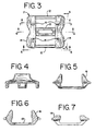
FIG. 3 is a top plan view of the bottom axle housing, wrap ofFIGS. 1 and 2 ; -
FIG. 4 is a side elevational view taken on line 4-4 ofFIG. 3 ; -
FIG. 5 is a side elevational view taken on line 5-5 ofFIG. 3 ; -
FIG. 6 is a sectional view taken on line 6-6 ofFIG. 3 ; -
FIG. 7 is a sectional view taken on line 7-7 ofFIG. 3 ; -
FIG. 8 is a plan view of the bottom side of the bottom axle housing wrap ofFIG. 3 ; -
FIG. 9 is a sectional view taken on line 9-9 ofFIG. 8 ; -
FIG. 10 is an end elevational view taken on line 10-10 ofFIG. 2 ; and -
FIG. 11 is a side elevational view of the top axle wrap ofFIGS. 1 and 2 . - Referring to
FIGS. 1 and 2 , a fabricated axle housing is indicated generally at 5 which is the axle housing for the front axle of a truck but which is representative of any axle housing, front or rear, of a truck. The system for clamping theaxle housing 5 to a combination suspension support member and leaf spring indicated generally at 6 comprises a bottom axle housing wrap indicated generally at 7, a top axle housing wrap indicated generally at 8, a top clamping plate or top spring pad indicated generally at 10 and four clamping bolts indicated generally at 11-11. Thespring 6 may correspond to the tapered convolute leaf spring shown and described inU.S. patent No. 5,938,221 to which reference should be made. - The bottom
axle housing wrap 11 is shown in greater detail inFIGS. 3-10 to which reference is now made. Thebottom axle wrap 11 may be either a casting or a forging with relatively wide openings in the interest of weight and cost reduction. It has two narrow side members 12-12 and a widercentral member 13. The opposite ends of themembers bolts 11 are located. Integrally formed on each of theend cross members 14 is an upwardly extending side orextension 16. - The bottom
axle housing wrap 11 is designed to telescopically mate with a top axle housing wrap 8 (FIG. 11 ) in the manner shown inFIG. 10 . Thetop axle wrap 8 has a width approximately equal to the distance between each pair ofbolts 11 and the width of the combination suspension member andspring 6 so as to permit the assembly shown inFIG. 1 . Thetop axle housing 8 has a pair of downwardly extendingside members 17 which fit over the opposite sides of theaxle housing 5 and between theupward extensions 16 on the bottomaxle housing wrap 7 as shown inFIG. 10 . As will be seen fromFIG. 10 thebolts 11 are spaced an appreciable distance from the downwardly extendingsides 17 of the topaxle housing wrap 8 as well as from the opposite sides of thebottom wall 18 of theaxle housing 5. As a result of this spacing, when thebolts 11 are tightened and placed under tension the opposite bottom edges of theaxle housing 5 will act as fulcrums and allow theextensions 16 on the bottomaxle housing wrap 7 to be tilted inwardly a small but appreciable amount against the downwardly extendingsides 17 on thetop axle wrap 8. This in turn will cause thedownward extensions 17 to press against the opposite sides 20-20 of theaxle housing 5. The result will be in the assembly shown inFIG. 1 that compressive forces will be uniformly applied to all four sides of theaxle housing 5 whereby the tendency of theaxle housing 5 to deform or collapse will be substantially eliminated. - If desired, the bottom and top axle housing wraps may be provided with liners (not shown) which act to improve the security of the clamped assembly.
Claims (3)
- A vehicle axle suspension comprising an axle (5) and, at each side of the vehicle, a combination support member and spring (6) and a system for clamping said axle adjacent one end thereof to said combination support member and spring, the clamping system comprising:a bottom axle wrap (7) on which a bottom side (18) of said axle is seated, and having upwardly extending sides (16) which act against opposite sides (20) of said axle;a top axle wrap (8) seated on the top side of said axle and engaging the underside of said combination support member and spring;a clamping plate (10) seated on the top of said combination support member and spring; anda plurality of bolts (11) holding the clamping system together;characterised in that the bolts (11) extend between the bottom axle wrap (7) and the clamping plate (10) spaced outwardly from the axle, andthe top axle wrap (8) has downward extensions (17) which embrace said opposite sides of the axle, fitting between said opposite axle sides and the upwardly extending sides (16) of the bottom axle wrap (7),whereby tensioning of the bolts (11) applies compressive forces against all four sides of said axle.
- A vehicle axle suspension according to claim 1 wherein the tightening of said bolts (11) causes said upwardly extending sides (16) to tilt inwardly and causes said downward extensions (17) to bear against opposite sides of the axle (5) whereby said axle is embraced on all four sides, on the bottom by said bottom axle wrap (7), on the top by said top axle wrap (8), and opposite sides by said downward extensions.
- Bottom axle wrap (7) and top axle wrap (8) suitable for use together in an axle suspension according to claim 1,
the bottom axle wrap (7) comprising a bottom seat to receive the axle in use, upward extensions (16) projecting up to either side thereof, and bolt holes (15) also positioned to either side thereof;
the top axle wrap (8) comprising a top seat to receive the axle and downward extensions (17) projecting down to either side thereof;
the downward side extensions (17) of the top wrap (8) being slidably fittable telescopically inside the respective upward side extensions (16) of the bottom wrap (7), so that when in use an axle is clamped between the top and bottom seats, by means of bolts extending from said bolt holes (15) of the bottom wrap (7) to a clamping plate above the top wrap (8), each downward side extension (17) projects between the respective upward extension (16) of the bottom wrap (7) and the respective side of the axle;
said bolt holes (15) of the bottom wrap (7) being spaced laterally outwardly relative to the downward side extensions (17) of the top wrap (8) whereby tensioning of said bolts in use tilts the upward extensions (16) inwardly against the downward extensions (17), to press them against the respective sides of the axle.
Applications Claiming Priority (3)
| Application Number | Priority Date | Filing Date | Title |
|---|---|---|---|
| US551901 | 2000-04-19 | ||
| US09/551,901 US6406008B1 (en) | 2000-04-19 | 2000-04-19 | Axle clamp attachment system |
| PCT/US2001/040544 WO2001079010A1 (en) | 2000-04-19 | 2001-04-18 | Axle clamp attachment system |
Publications (4)
| Publication Number | Publication Date |
|---|---|
| EP1274595A1 EP1274595A1 (en) | 2003-01-15 |
| EP1274595A4 EP1274595A4 (en) | 2005-12-28 |
| EP1274595B1 true EP1274595B1 (en) | 2008-10-08 |
| EP1274595B8 EP1274595B8 (en) | 2008-12-24 |
Family
ID=24203135
Family Applications (1)
| Application Number | Title | Priority Date | Filing Date |
|---|---|---|---|
| EP01929066A Expired - Lifetime EP1274595B8 (en) | 2000-04-19 | 2001-04-18 | Axle clamp attachment system |
Country Status (13)
| Country | Link |
|---|---|
| US (1) | US6406008B1 (en) |
| EP (1) | EP1274595B8 (en) |
| JP (1) | JP5001499B2 (en) |
| KR (1) | KR100849605B1 (en) |
| AT (1) | ATE410320T1 (en) |
| AU (2) | AU5585201A (en) |
| BR (1) | BR0110192B1 (en) |
| CA (1) | CA2405891C (en) |
| DE (1) | DE60136058D1 (en) |
| ES (1) | ES2313953T3 (en) |
| MX (1) | MXPA02010243A (en) |
| NZ (1) | NZ522403A (en) |
| WO (1) | WO2001079010A1 (en) |
Families Citing this family (28)
| Publication number | Priority date | Publication date | Assignee | Title |
|---|---|---|---|---|
| US7445220B2 (en) * | 2004-02-06 | 2008-11-04 | Daimler Trucks North America Llc | Vehicle axle apparatus |
| US7175190B2 (en) * | 2004-03-30 | 2007-02-13 | Arvinmeritor Technology, Llc | Horizontal mount of suspension element to axle |
| US20070176383A1 (en) * | 2005-12-12 | 2007-08-02 | Winter David C | Trailer |
| US20070132208A1 (en) * | 2005-12-12 | 2007-06-14 | Winter David C | Trailer |
| NL1032409C2 (en) * | 2006-09-01 | 2008-03-04 | Weweler Nv | Connection construction for a wheel axle. |
| US8136825B2 (en) * | 2007-03-08 | 2012-03-20 | Arvinmeritor Technology, Llc | Tubular axle beam suspension mount |
| JP4962553B2 (en) * | 2009-11-05 | 2012-06-27 | 株式会社豊田自動織機 | Support structure of axle housing in towing tractor |
| DE102010009304A1 (en) * | 2010-02-25 | 2011-08-25 | MAN Truck & Bus AG, 80995 | Device for connecting a spring element to a commercial vehicle axle |
| US8820760B2 (en) * | 2011-12-28 | 2014-09-02 | Vdl Weweler B.V. | Wheel axle suspension |
| DE102012004405B4 (en) * | 2012-03-02 | 2022-01-20 | Schomäcker Federnwerk GmbH | Device for connecting an axle body to a link |
| US8827289B2 (en) * | 2012-08-06 | 2014-09-09 | Hendrickson Usa, L.L.C. | Reduced weight axle mounting assembly for vehicle suspension systems |
| US9114685B2 (en) * | 2012-08-06 | 2015-08-25 | Hendrickson Usa, L.L.C. | Reduced weight axle coupling assembly for vehicle suspension systems |
| DE102012024941A1 (en) * | 2012-12-19 | 2014-06-26 | Schomäcker Federnwerk GmbH | Device for connecting axle body of wheel axle of vehicle with control arm, has head plate comprising two brackets partially limiting control arm and are provided at distance from each other |
| US9568033B2 (en) | 2013-03-15 | 2017-02-14 | Hendrickson Usa, L.L.C. | Systems and methods for improving bolted joints |
| US9605700B2 (en) * | 2013-03-15 | 2017-03-28 | Hendrickson Usa, L.L.C. | Systems and methods for improving bolted joints |
| US20150316202A1 (en) * | 2014-04-29 | 2015-11-05 | Entertainment Structural Products | Truss Adapter for Mounting Objects on Space Frame Truss |
| US10077868B2 (en) * | 2014-04-29 | 2018-09-18 | Entertainment Structural Products, Inc. | Truss adapter for mounting objects on space frame truss |
| US9770956B2 (en) | 2015-03-20 | 2017-09-26 | Hendrickson Usa L.L.C. | Axle bracket liner |
| US10850583B2 (en) * | 2016-12-30 | 2020-12-01 | Ingersoll-Rand Company | Suspension perch bracket for a utility vehicle |
| US10316511B1 (en) | 2017-02-14 | 2019-06-11 | Valmont Industries | Bolt calibrated angle mainstay for tower construction and method for use |
| CN111278669B (en) * | 2017-09-23 | 2023-12-05 | 亨德里克森美国有限责任公司 | Formed axle seat assembly |
| US11110765B2 (en) | 2019-05-31 | 2021-09-07 | Mahindra N.A. Tech Center | Suspension spring saddle |
| RU195939U1 (en) * | 2019-10-14 | 2020-02-11 | Публичное акционерное общество "КАМАЗ" | VEHICLE SPRING SUPPORT |
| WO2021096627A1 (en) * | 2019-11-11 | 2021-05-20 | Valmont Industries, Inc. | Bolt calibrated angle mainstay wall connection system and method for use |
| US11273680B2 (en) * | 2020-04-10 | 2022-03-15 | Dana Heavy Vehicle Systems Group, Llc | Suspension system |
| EP4008571A1 (en) * | 2020-12-01 | 2022-06-08 | Volvo Truck Corporation | Axle fixation for a vehicle axle |
| US12085204B2 (en) | 2021-12-14 | 2024-09-10 | Firestone Industrial Products Company, Llc | Mounting bracket assemblies as well as suspension assemblies, kits and methods including same |
| US12391068B1 (en) | 2024-06-14 | 2025-08-19 | Textron Inc. | Axle assembly with interchangeable shafts |
Family Cites Families (16)
| Publication number | Priority date | Publication date | Assignee | Title |
|---|---|---|---|---|
| US2072198A (en) * | 1936-05-26 | 1937-03-02 | Davis William Edwin | Spring and spindle bracket |
| US3437333A (en) * | 1966-10-24 | 1969-04-08 | North American Rockwell | Spring seat |
| US3494609A (en) * | 1967-10-11 | 1970-02-10 | Western Unit Corp | Leaf spring and axle seats |
| DE2635329C3 (en) * | 1976-08-05 | 1979-04-19 | Stahlwerke Brueninghaus Gmbh, 5840 Schwerte | Spring band |
| GB2186316B (en) * | 1986-02-08 | 1989-11-01 | British Building & Engineering | Scaffold fitting |
| JPH0810532Y2 (en) * | 1990-06-30 | 1996-03-29 | いすゞ自動車株式会社 | Axle case spring seat structure |
| JP2917710B2 (en) * | 1992-08-28 | 1999-07-12 | 三菱自動車工業株式会社 | Rear wheel steering device such as truck |
| US5328159A (en) * | 1992-08-18 | 1994-07-12 | Dana Corporation | Axle housing attachment assembly |
| DE9305039U1 (en) * | 1993-04-02 | 1994-08-04 | Trenkamp & Gehle GmbH, 49413 Dinklage | Device for connecting trailing arm units to a wheel axle of commercial vehicles |
| US5476251A (en) * | 1994-08-15 | 1995-12-19 | Dana Corporation | Axle bracket providing improved support |
| JPH08101091A (en) * | 1994-09-30 | 1996-04-16 | Seibu Gas Kk | Method and apparatus for inspecting shut off of valve |
| CA2220171A1 (en) * | 1995-05-16 | 1996-11-21 | Nai Neway, Inc. | Trailing arm suspension with wrapper compression axle mounting |
| NL1003214C2 (en) * | 1996-05-28 | 1997-12-03 | Weweler Nv | Axle construction for a vehicle, as well as axle pad and clamping plate therefor. |
| US5881606A (en) * | 1997-02-26 | 1999-03-16 | Trek Bicycle Corporation | Bicycle handlebar attachment device |
| NL1009580C2 (en) * | 1998-07-07 | 2000-01-10 | Weweler Nv | Clamp to secure vehicle axle body to longitudinal suspension arm with adjustment to accommodate axles over small range of cross-sectional dimensions with no mechanical play |
| DE19856706C1 (en) * | 1998-12-09 | 2000-04-13 | Daimler Chrysler Ag | Connector for motor vehicle axle to suspension has elastic wire saddle to fit over axle with free ends welded together |
-
2000
- 2000-04-19 US US09/551,901 patent/US6406008B1/en not_active Expired - Lifetime
-
2001
- 2001-04-18 ES ES01929066T patent/ES2313953T3/en not_active Expired - Lifetime
- 2001-04-18 AU AU5585201A patent/AU5585201A/en active Pending
- 2001-04-18 CA CA002405891A patent/CA2405891C/en not_active Expired - Lifetime
- 2001-04-18 MX MXPA02010243A patent/MXPA02010243A/en active IP Right Grant
- 2001-04-18 JP JP2001576289A patent/JP5001499B2/en not_active Expired - Fee Related
- 2001-04-18 AT AT01929066T patent/ATE410320T1/en not_active IP Right Cessation
- 2001-04-18 AU AU2001255852A patent/AU2001255852B2/en not_active Ceased
- 2001-04-18 KR KR1020027013976A patent/KR100849605B1/en not_active Expired - Fee Related
- 2001-04-18 DE DE60136058T patent/DE60136058D1/en not_active Expired - Lifetime
- 2001-04-18 WO PCT/US2001/040544 patent/WO2001079010A1/en not_active Ceased
- 2001-04-18 BR BRPI0110192-7A patent/BR0110192B1/en not_active IP Right Cessation
- 2001-04-18 EP EP01929066A patent/EP1274595B8/en not_active Expired - Lifetime
- 2001-04-18 NZ NZ522403A patent/NZ522403A/en unknown
Also Published As
| Publication number | Publication date |
|---|---|
| CA2405891C (en) | 2008-11-25 |
| EP1274595A4 (en) | 2005-12-28 |
| BR0110192A (en) | 2003-06-24 |
| ES2313953T3 (en) | 2009-03-16 |
| CA2405891A1 (en) | 2001-10-25 |
| JP2003531048A (en) | 2003-10-21 |
| BR0110192B1 (en) | 2011-05-03 |
| JP5001499B2 (en) | 2012-08-15 |
| EP1274595B8 (en) | 2008-12-24 |
| EP1274595A1 (en) | 2003-01-15 |
| DE60136058D1 (en) | 2008-11-20 |
| MXPA02010243A (en) | 2003-04-25 |
| AU5585201A (en) | 2001-10-30 |
| KR20030022786A (en) | 2003-03-17 |
| KR100849605B1 (en) | 2008-07-31 |
| US6406008B1 (en) | 2002-06-18 |
| ATE410320T1 (en) | 2008-10-15 |
| AU2001255852B2 (en) | 2004-11-11 |
| WO2001079010A1 (en) | 2001-10-25 |
| NZ522403A (en) | 2007-08-31 |
Similar Documents
| Publication | Publication Date | Title |
|---|---|---|
| EP1274595B8 (en) | Axle clamp attachment system | |
| AU2001255852A1 (en) | Axle clamp attachment system | |
| US5328159A (en) | Axle housing attachment assembly | |
| AU716460B2 (en) | Means for and method of mounting a suspension member to an axle housing | |
| EP1089889B1 (en) | Trailing arm axle/suspension system | |
| EP2879892B1 (en) | Motor vehicle axle suspension with longitudinal leaf spring | |
| CA2431724C (en) | Axle suspension connection | |
| EP0722401A1 (en) | End section of frame member | |
| US7175190B2 (en) | Horizontal mount of suspension element to axle | |
| US20050167972A1 (en) | Fender assembly and adjustable mounting bracket therefor | |
| CA2411676C (en) | Hangers for trailer height adjustment | |
| US12570115B2 (en) | Offset multi-point under bed hitch mounting system and method | |
| EP0881116A2 (en) | Motor-vehicle seat frame | |
| US20020096854A1 (en) | Anchoring system of spring to vehicle axle and spring for vehicle axle | |
| US6158723A (en) | Stabilizer for leaf spring suspension device | |
| US20050269795A1 (en) | Vehicle axle suspension bracket with squeeze attachment interface | |
| JP2555639Y2 (en) | Vehicle suspension arm | |
| JPH10166826A (en) | Vehicle leaf spring mounting structure | |
| JPH083725Y2 (en) | Axle case spring seat structure | |
| AU2001100065A4 (en) | A supplementary spring assembly and connection means therefor | |
| JPH08295209A (en) | Car body fixing device | |
| AU2001100067A9 (en) | A supplementary spring assembly and connection means therefor | |
| AU2001100066A9 (en) | Spring assembly and connection means therefor | |
| KR20040098731A (en) | Jig for fixing tire to wheel axel of automobile |
Legal Events
| Date | Code | Title | Description |
|---|---|---|---|
| PUAI | Public reference made under article 153(3) epc to a published international application that has entered the european phase |
Free format text: ORIGINAL CODE: 0009012 |
|
| 17P | Request for examination filed |
Effective date: 20021105 |
|
| AK | Designated contracting states |
Kind code of ref document: A1 Designated state(s): AT BE CH CY DE DK ES FI FR GB GR IE IT LI LU MC NL PT SE TR |
|
| AX | Request for extension of the european patent |
Free format text: AL;LT;LV;MK;RO;SI |
|
| RAP1 | Party data changed (applicant data changed or rights of an application transferred) |
Owner name: HENDRICKSON INTERNATIONAL CORPORATION |
|
| A4 | Supplementary search report drawn up and despatched |
Effective date: 20051116 |
|
| 17Q | First examination report despatched |
Effective date: 20060223 |
|
| GRAP | Despatch of communication of intention to grant a patent |
Free format text: ORIGINAL CODE: EPIDOSNIGR1 |
|
| GRAS | Grant fee paid |
Free format text: ORIGINAL CODE: EPIDOSNIGR3 |
|
| GRAA | (expected) grant |
Free format text: ORIGINAL CODE: 0009210 |
|
| AK | Designated contracting states |
Kind code of ref document: B1 Designated state(s): AT BE CH CY DE DK ES FI FR GB GR IE IT LI LU MC NL PT SE TR |
|
| REG | Reference to a national code |
Ref country code: GB Ref legal event code: FG4D |
|
| RBV | Designated contracting states (corrected) |
Designated state(s): BE DE ES FR GB IT NL SE |
|
| RBV | Designated contracting states (corrected) |
Designated state(s): BE DE ES FR GB IT NL SE TR |
|
| REG | Reference to a national code |
Ref country code: IE Ref legal event code: FG4D |
|
| REF | Corresponds to: |
Ref document number: 60136058 Country of ref document: DE Date of ref document: 20081120 Kind code of ref document: P |
|
| REG | Reference to a national code |
Ref country code: SE Ref legal event code: TRGR |
|
| REG | Reference to a national code |
Ref country code: ES Ref legal event code: FG2A Ref document number: 2313953 Country of ref document: ES Kind code of ref document: T3 |
|
| PLBE | No opposition filed within time limit |
Free format text: ORIGINAL CODE: 0009261 |
|
| STAA | Information on the status of an ep patent application or granted ep patent |
Free format text: STATUS: NO OPPOSITION FILED WITHIN TIME LIMIT |
|
| 26N | No opposition filed |
Effective date: 20090709 |
|
| REG | Reference to a national code |
Ref country code: FR Ref legal event code: PLFP Year of fee payment: 16 |
|
| PGFP | Annual fee paid to national office [announced via postgrant information from national office to epo] |
Ref country code: ES Payment date: 20160426 Year of fee payment: 16 |
|
| PGFP | Annual fee paid to national office [announced via postgrant information from national office to epo] |
Ref country code: TR Payment date: 20160406 Year of fee payment: 16 Ref country code: BE Payment date: 20160427 Year of fee payment: 16 |
|
| REG | Reference to a national code |
Ref country code: FR Ref legal event code: PLFP Year of fee payment: 17 |
|
| REG | Reference to a national code |
Ref country code: BE Ref legal event code: MM Effective date: 20170430 |
|
| REG | Reference to a national code |
Ref country code: FR Ref legal event code: PLFP Year of fee payment: 18 |
|
| PG25 | Lapsed in a contracting state [announced via postgrant information from national office to epo] |
Ref country code: BE Free format text: LAPSE BECAUSE OF NON-PAYMENT OF DUE FEES Effective date: 20170430 |
|
| PGFP | Annual fee paid to national office [announced via postgrant information from national office to epo] |
Ref country code: NL Payment date: 20180426 Year of fee payment: 18 |
|
| REG | Reference to a national code |
Ref country code: ES Ref legal event code: FD2A Effective date: 20180704 |
|
| PG25 | Lapsed in a contracting state [announced via postgrant information from national office to epo] |
Ref country code: ES Free format text: LAPSE BECAUSE OF NON-PAYMENT OF DUE FEES Effective date: 20170419 |
|
| PGFP | Annual fee paid to national office [announced via postgrant information from national office to epo] |
Ref country code: DE Payment date: 20180427 Year of fee payment: 18 |
|
| PGFP | Annual fee paid to national office [announced via postgrant information from national office to epo] |
Ref country code: FR Payment date: 20180425 Year of fee payment: 18 Ref country code: IT Payment date: 20180423 Year of fee payment: 18 |
|
| PGFP | Annual fee paid to national office [announced via postgrant information from national office to epo] |
Ref country code: SE Payment date: 20180427 Year of fee payment: 18 |
|
| PGFP | Annual fee paid to national office [announced via postgrant information from national office to epo] |
Ref country code: GB Payment date: 20180427 Year of fee payment: 18 |
|
| REG | Reference to a national code |
Ref country code: DE Ref legal event code: R119 Ref document number: 60136058 Country of ref document: DE |
|
| REG | Reference to a national code |
Ref country code: SE Ref legal event code: EUG |
|
| REG | Reference to a national code |
Ref country code: NL Ref legal event code: MM Effective date: 20190501 |
|
| GBPC | Gb: european patent ceased through non-payment of renewal fee |
Effective date: 20190418 |
|
| PG25 | Lapsed in a contracting state [announced via postgrant information from national office to epo] |
Ref country code: SE Free format text: LAPSE BECAUSE OF NON-PAYMENT OF DUE FEES Effective date: 20190419 Ref country code: DE Free format text: LAPSE BECAUSE OF NON-PAYMENT OF DUE FEES Effective date: 20191101 Ref country code: GB Free format text: LAPSE BECAUSE OF NON-PAYMENT OF DUE FEES Effective date: 20190418 Ref country code: NL Free format text: LAPSE BECAUSE OF NON-PAYMENT OF DUE FEES Effective date: 20190501 |
|
| PG25 | Lapsed in a contracting state [announced via postgrant information from national office to epo] |
Ref country code: FR Free format text: LAPSE BECAUSE OF NON-PAYMENT OF DUE FEES Effective date: 20190430 |
|
| PG25 | Lapsed in a contracting state [announced via postgrant information from national office to epo] |
Ref country code: IT Free format text: LAPSE BECAUSE OF NON-PAYMENT OF DUE FEES Effective date: 20190418 |
|
| PG25 | Lapsed in a contracting state [announced via postgrant information from national office to epo] |
Ref country code: TR Free format text: LAPSE BECAUSE OF NON-PAYMENT OF DUE FEES Effective date: 20170418 |