EP1274214A2 - Wireless communication device with a combined reset and suspend state on layer 2 - Google Patents
Wireless communication device with a combined reset and suspend state on layer 2 Download PDFInfo
- Publication number
- EP1274214A2 EP1274214A2 EP02011770A EP02011770A EP1274214A2 EP 1274214 A2 EP1274214 A2 EP 1274214A2 EP 02011770 A EP02011770 A EP 02011770A EP 02011770 A EP02011770 A EP 02011770A EP 1274214 A2 EP1274214 A2 EP 1274214A2
- Authority
- EP
- European Patent Office
- Prior art keywords
- layer
- state
- interface
- reset
- communications
- Prior art date
- Legal status (The legal status is an assumption and is not a legal conclusion. Google has not performed a legal analysis and makes no representation as to the accuracy of the status listed.)
- Withdrawn
Links
Images


Classifications
-
- H—ELECTRICITY
- H04—ELECTRIC COMMUNICATION TECHNIQUE
- H04W—WIRELESS COMMUNICATION NETWORKS
- H04W88/00—Devices specially adapted for wireless communication networks, e.g. terminals, base stations or access point devices
- H04W88/02—Terminal devices
-
- H—ELECTRICITY
- H04—ELECTRIC COMMUNICATION TECHNIQUE
- H04L—TRANSMISSION OF DIGITAL INFORMATION, e.g. TELEGRAPHIC COMMUNICATION
- H04L69/00—Network arrangements, protocols or services independent of the application payload and not provided for in the other groups of this subclass
- H04L69/30—Definitions, standards or architectural aspects of layered protocol stacks
- H04L69/32—Architecture of open systems interconnection [OSI] 7-layer type protocol stacks, e.g. the interfaces between the data link level and the physical level
- H04L69/322—Intralayer communication protocols among peer entities or protocol data unit [PDU] definitions
- H04L69/324—Intralayer communication protocols among peer entities or protocol data unit [PDU] definitions in the data link layer [OSI layer 2], e.g. HDLC
-
- H—ELECTRICITY
- H04—ELECTRIC COMMUNICATION TECHNIQUE
- H04L—TRANSMISSION OF DIGITAL INFORMATION, e.g. TELEGRAPHIC COMMUNICATION
- H04L69/00—Network arrangements, protocols or services independent of the application payload and not provided for in the other groups of this subclass
- H04L69/30—Definitions, standards or architectural aspects of layered protocol stacks
- H04L69/32—Architecture of open systems interconnection [OSI] 7-layer type protocol stacks, e.g. the interfaces between the data link level and the physical level
-
- H—ELECTRICITY
- H04—ELECTRIC COMMUNICATION TECHNIQUE
- H04L—TRANSMISSION OF DIGITAL INFORMATION, e.g. TELEGRAPHIC COMMUNICATION
- H04L69/00—Network arrangements, protocols or services independent of the application payload and not provided for in the other groups of this subclass
- H04L69/30—Definitions, standards or architectural aspects of layered protocol stacks
- H04L69/32—Architecture of open systems interconnection [OSI] 7-layer type protocol stacks, e.g. the interfaces between the data link level and the physical level
- H04L69/322—Intralayer communication protocols among peer entities or protocol data unit [PDU] definitions
- H04L69/323—Intralayer communication protocols among peer entities or protocol data unit [PDU] definitions in the physical layer [OSI layer 1]
-
- H—ELECTRICITY
- H04—ELECTRIC COMMUNICATION TECHNIQUE
- H04W—WIRELESS COMMUNICATION NETWORKS
- H04W52/00—Power management, e.g. Transmission Power Control [TPC] or power classes
- H04W52/02—Power saving arrangements
- H04W52/0209—Power saving arrangements in terminal devices
- H04W52/0225—Power saving arrangements in terminal devices using monitoring of external events, e.g. the presence of a signal
- H04W52/0238—Power saving arrangements in terminal devices using monitoring of external events, e.g. the presence of a signal where the received signal is an unwanted signal, e.g. interference or idle signal
-
- H—ELECTRICITY
- H04—ELECTRIC COMMUNICATION TECHNIQUE
- H04W—WIRELESS COMMUNICATION NETWORKS
- H04W76/00—Connection management
-
- H—ELECTRICITY
- H04—ELECTRIC COMMUNICATION TECHNIQUE
- H04W—WIRELESS COMMUNICATION NETWORKS
- H04W80/00—Wireless network protocols or protocol adaptations to wireless operation
- H04W80/02—Data link layer protocols
-
- Y—GENERAL TAGGING OF NEW TECHNOLOGICAL DEVELOPMENTS; GENERAL TAGGING OF CROSS-SECTIONAL TECHNOLOGIES SPANNING OVER SEVERAL SECTIONS OF THE IPC; TECHNICAL SUBJECTS COVERED BY FORMER USPC CROSS-REFERENCE ART COLLECTIONS [XRACs] AND DIGESTS
- Y02—TECHNOLOGIES OR APPLICATIONS FOR MITIGATION OR ADAPTATION AGAINST CLIMATE CHANGE
- Y02D—CLIMATE CHANGE MITIGATION TECHNOLOGIES IN INFORMATION AND COMMUNICATION TECHNOLOGIES [ICT], I.E. INFORMATION AND COMMUNICATION TECHNOLOGIES AIMING AT THE REDUCTION OF THEIR OWN ENERGY USE
- Y02D30/00—Reducing energy consumption in communication networks
- Y02D30/70—Reducing energy consumption in communication networks in wireless communication networks
Definitions
- the present invention relates to a state model for a wireless communications device.
- the present invention discloses a finite state machine for the wireless device that includes a reset/suspend state.
- FIG.1 is a simplified block diagram of the prior art communications model.
- a prior art wireless system includes a first device 20 and a second device 30, both of which are in wireless communications with each other.
- the first device 20 may be a mobile unit, such as a cellular telephone
- the second device 30 may be a base station.
- An application 24 on the first device 20 needs to send data 24d to an application 34 on the second device 30.
- the application 24 connects with a layer 3 interface 23 (termed the radio resource control (RRC)), and passes the data 24d to the layer 3 interface 23.
- the layer 3 interface 23 uses the data 24d to form a layer 3 protocol data unit (PDU) 23p.
- RRC radio resource control
- the layer 3 PDU 23p includes a layer 3 header 23h and data 23d, which is identical to the data 24d.
- the layer 3 header 23h in the layer 3 PDU 23p contains information needed by the corresponding layer 3 interface 33 on the second device 30 to effect proper communications.
- the layer 3 interface 23 then passes the layer 3 PDU 23p to a layer 2 interface 22.
- the layer 2 interface 22 also termed the radio link control (RLC) uses the layer 3 PDU 23p to build one or more layer 2 PDUs 22p.
- RLC radio link control
- each layer 2 PDU 22p has the same fixed size.
- each layer 2 PDU 22p contains a data region 22d, and a layer 2 header 22h.
- the data 23d has been broken into two layer 2 PDUs 22p.
- the layer 3 header 23h is placed in the data region 22d of a layer 2 PDU 22p.
- the layer 3 header 23h holds no significance for the layer 2 interface 22, and is simply treated as data.
- the layer 2 interface 22 then passes the layer 2 PDUs 22p to a layer 1 interface 21.
- the layer 1 interface 21 is the physical interface, and does all the actual transmitting and receiving of data.
- the layer 1 interface 21 accepts the layer 2 PDUs 22p and uses them to build layer 1 PDUs 21p.
- each layer 1 PDU 21p has a data region 21d and a layer 1 header 21h. Note that the layer 3 header 23h and layer 2 headers 22h are no more important to the layer 1 interface 21 than the application data 24d.
- the layer 1 interface 21 then transmits the layer 1 PDUs 21p to the second device 30.
- a reverse process occurs on the second device 30.
- a layer 1 interface 31 on the second device 30 removes the layer 1 headers 31h from each received layer 1 PDU 31p. This leaves only the layer 1 data regions 31d, which are, in effect, layer 2 PDUs. These layer 1 data regions 31d are passed up to a layer 2 interface 32.
- the layer 2 interface 32 accepts the Layer 2 PDUs 32p and uses the layer 2 headers 32h to determine how to assemble the layer 2 PDUs 32p into appropriate layer 3 PDUs. In the example depicted in Fig.1, the layer 2 headers 32h are stripped from the layer 2 PDUs 32p, leaving only the data regions 32d.
- the data regions 32d are appended to each other in the proper order, and then passed up to the layer 3 interface 33.
- the layer 3 interface 33 accepts the layer 3 PDU 33p from the layer 2 interface 32, strips the header 33h from the layer 3 PDU 33p, and passes the data region 33d to the application 34.
- the application 34 thus has data 34d that should be identical to the data 24d sent by the application 24 on the first device 20.
- Fig.2 is simplified block diagram of a layer 2 PDU 40.
- the layer 2 PDU 40 has a layer 2 header 41 and a data region 45.
- the data region 45 is used to carry layer 3 PDUs 23p received from the layer 3 interface 23.
- the layer 2 header 41 includes a data/control indicator bit 42, a sequence number field 43, and additional fields 44.
- the additional fields 44 are not of direct relevance to the present invention, and so will not be discussed.
- the data/control bit 42 is used to indicate if the layer 2 PDU 40 is a data PDU or a control PDU. Data PDUs are used to carry layer 3 data.
- Control PDUs are generated internally by the layer 2 interface 22, 32 and are used exclusively for signaling between the layer 2 interfaces 22 and 32, such as the passing of reset and reset acknowledgment signals. Control PDUs are thus never passed up to the layer 3 interface 23, 33.
- the sequence number field 43 contains a 12-bit or 7-bit value that is used to reassemble the layer 2 PDUs 40 into layer 3 PDUs 33p. Each layer 2 PDU 22p is transmitted with a successively higher value in the sequence number field 43, and in this manner the layer 2 interface 32 knows the correct ordering of received layer 2 PDUs 32p.
- Figs.3 and 4 are state model diagrams of a prior art layer 2 interface.
- the prior art layer 2 interface 22, 32 is designed as a finite state machine.
- Fig.3 depicts the state model for the layer 2 interface 22, 32 when a reset command is performed.
- Fig.4 depicts the state model when a local suspend command is performed. Transitions between states are noted by arrows in Figs.3 and 4. Received signals associated with a state transition are noted above a horizontal line, and signals sent in response to the state transition are noted below the horizontal line.
- the layer 2 interface 22, 32 includes a null state 50, a data transfer ready state 52, a reset pending state 54 and a local suspend state 56.
- the first device 20 will be used as an example.
- the layer 2 interface 22 When the layer 2 interface 22 is in the null state 50, the layer 2 interface 22 has no established wireless channel 11 with the second device 30. The layer 2 interface 22 of the first device 20 thus cannot transmit any layer 2 PDUs 22p to the second device 30.
- the application 24 determines that it wishes to send the data 24d to the application 34, the application 24 signals this intent to the layer 3 interface 23.
- the layer 3 interface 23 then performs whatever functions are necessary to establish the channel 11 with the second device 30.
- the layer 3 interface 23 sends an establish primitive to the layer 2 interface 22.
- the layer 2 interface 22 transitions from the null state 50 to the data transfer state 52.
- the layer 2 interface 22 establishes the wireless channel 11 with the second device 30. While in the data transfer ready state 52, the first device 20 can freely transmit layer 2 PDUs 22p along the channel 11. At any time when the layer 2 interface 22 is in the data transfer state 52 and receives a release primitive from the layer 3 interface 23, the layer 2 interface 22 will transition back to the null state 50. In the process of doing so, the layer 2 interface 22 will close down the channel 11.
- the layer 2 interface 22 may determine that communications along the channel 11 are malfunctioning. In this case, the layer 2 interface 22 will desire to reset the communications system. To ensure that the entire system is reset, both the first device 20 and the second device 30 must be reset. To reset the second device 30, the layer 2 interface 22 generates a reset control PDU, and sends the reset control PDU along the channel 11 to the layer 2 interface 32 on the second device 30. The layer 2 interface 22 on the first device 20 then transitions from the data transfer state 52 to the reset pending state 54. While in the reset pending state 54, the layer 2 interface 22 will transmit no PDUs 22p to the second device 30 along the channel 11. This effectively halts communications along the channel 11.
- the layer 2 interface 22 remains in the reset pending state 54 until reception of a reset acknowledgment control PDU from the layer 2 interface 32 on the second device 30.
- This reset acknowledgment control PDU informs the layer 2 interface 22 that the layer 2 interface 32 received the reset control PDU and internally reset the layer 2 interface 32.
- the layer 2 interface 22 transitions from the reset pending state 54 to the data transfer ready state 52, and in the process of doing so resets the entire layer 2 state machine 22, such as flushing transmission and reception buffers, setting control variables to default values, etc. Communications along channel 11 are in this way reset back to default conditions so as to reestablish normal communications between the first device 20 and the second device 30.
- the layer 2 interface 22 will transition to the null state 50. In the process of doing so, the layer 2 interface 22 will close down the channel 11. Also note that the layer 2 interface 22 may receive a reset control PDU from the layer 2 interface 32 of the second station 30 while in the data transfer ready state 52. Upon reception of such a layer 2 control PDU, the layer 2 interface 22 will internally reset the layer 2 interface state machine 22 for the channel 11, and then transmit a reset acknowledgment control PDU to the layer 2 interface 32. The layer 2 interface 22 remains, however, in the data transfer ready state 52 during this exchange.
- the local suspend state 56 is used to temporarily halt the transfer of layer 2 PDUs 22p along the channel 11, and is initiated by a suspend-request primitive from the layer 3 interface 23.
- the primary purpose of the local suspend state 56 is to ensure a proper ciphering configuration change between the first device 20 and the second device 30 along the channel 11.
- the layer 2 interface 22 may transition to the local suspend state 56 upon reception of the suspend-request primitive from the layer 3 interface 23.
- the suspend-request primitive contains a variable N 56n, which indicates a sequence number value 43.
- the layer 2 interface 22 may transmit along channel 11 layer 2 PDUs 22p with sequence number values 43 that are sequentially before a value indicated by N 56n.
- any layer 2 PDU 22p having a sequence number value 43 that is sequentially after the value indicated by N 56n will not be transmitted by the layer 2 interface 22p along the channel 11.
- the layer 2 interface 22 Upon reception of a resume primitive from the layer 3 interface 23, the layer 2 interface 22 will transition from the local suspend state 56 back to the data transfer ready state 52.
- the prior art state models of Figs.3 and 4 cannot account for transitions between the local suspend state 56 and the reset pending state 54, although such transitions are assumed possible. For example, it is not difficult to imagine a situation arising in which, while the layer 2 interface 22 is in the local suspend state 56, the layer 2 interface 22 detects a communications error along the channel 11 and desires to initiate a reset procedure. Sending a reset control PDU to the second device 30 along the channel 11 would force the layer 2 interface 22 to transition into the reset pending state 54 to await the resulting reset acknowledgment control PDU from the layer 2 interface 32 of the second device 30. According to the state model of Fig.3, reception of the reset acknowledgment control PDU should cause the layer 2 interface 22 to transition into the data transfer ready state 52.
- the layer 2 interface should more properly return back to the local suspend state 56.
- the reset pending state 54 and the local suspend state 56 cannot be "memoryless" states, but must remember from which state they transitioned so as to properly return to that state.
- a proper state model should have no hysteresis; i.e., the reaction of a state to inputs should not depend upon past reactions but only upon the present inputs, as this leads to a simpler and more consistent implementation. Internal consistency is essential to avoid programming bugs arising from unexpected state interactions within the model.
- the preferred embodiment of the present invention discloses a wireless communications device that transacts muti-layered communications with a second wireless device.
- the wireless communications device has a processor, and a program in memory that is executed by the processor to effect a multi-layered communications protocol.
- the multi-layered communications protocol has a layer 3 interface in communications with a layer 2 interface .
- the layer 2 interface transmits and receives layer 2 communications data.
- the layer 2 interface utilizes a null state, a data transfer state, a reset pending state, a local suspend state and a reset/suspend state. While in the null state, the layer 2 interface has no established layer 2 wireless connection with the second wireless device.
- the layer 2 interface While in the data transfer state, the layer 2 interface is in wireless communications with a layer 2 interface on the second wireless device and transmits the layer 2 communications data to the layer 2 interface on the second wireless device.
- the processor switches from the null state to the data transfer state according to an establish primitive from the layer 3 interface, and switches from the data transfer state to the null state according to a release primitive from the layer 3 interface.
- the layer 2 interface While in the reset pending state, the layer 2 interface is in wireless communications with the layer 2 interface on the second wireless device and the transmission of the layer 2 communications data is halted.
- the processor switches from the data transfer state to the reset pending state when a protocol error is found by the layer 2 interface, switches from the reset pending state to the data transfer state according to a reset acknowledge signal received from the second wireless device, and switches from the reset pending state to the null state according to the release primitive from the layer 3 interface.
- the layer 2 interface While in the local suspend state, the layer 2 interface is in wireless communications with the layer 2 interface on the second wireless device and halts the transmission of the layer 2 communications data after a predetermined event indicated by the layer 3 interface.
- the processor switches from the data transfer state to the local suspend state according to a suspend primitive from the layer 3 interface, switches from the local suspend state to the data transfer state according to a resume primitive from the layer 3 interface, and switches from the local suspend state to the null state according to the release primitive from the layer 3 interface.
- the layer 2 interface is in wireless communications with the layer 2 interface on the second wireless device and the transmission of the layer 2 communications data is halted.
- the processor switches from the reset/suspend state to the reset pending state according to the resume primitive from the layer 3 interface, switches from the reset pending state to the reset/suspend state according to the suspend primitive from the layer 3 interface, switches from the reset/suspend state to the local suspend state according to the reset acknowledge signal received from the second wireless device, switches from the local suspend state to the reset/suspend state when a protocol error is found by the layer 2 interface, and switches from the reset/suspend state to the null state according to the release primitive from the layer 3 interface.
- Fig.1 is a simplified block diagram of a prior art communications model.
- Fig.2 is simplified block diagram of a layer 2 protocol data unit (PDU).
- PDU protocol data unit
- Fig.3 depicts a state model for a prior art layer 2 interface when a reset command is performed.
- Fig.4 depicts a state model for a prior art layer 2 interface when a local suspend command is performed.
- Fig.5 illustrates a state model according to the present invention.
- Fig.6 presents a simplified block diagram a wireless communications device that implements the state model depicted in Fig.5.
- a wireless communications device may be a mobile telephone, a handheld transceiver, a base station, a personal data assistant (PDA), a computer, or any other device that requires a wireless exchange of data. It should be understood that many means may be used for the physical layer 1 to effect wireless transmissions, and that any such means may be used for the system hereinafter disclosed.
- PDA personal data assistant
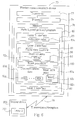
- Fig.5 depicts a state model 60 for a layer 2 interface of wireless communications device according to the present invention.
- the state model 60 of the present invention provides a unique reset/suspend state 68 that enables the state model 60 to function based solely on inputs.
- the state model 60 with the reset/suspend state 68 thus does not require a wireless device to recall a previous state from which a transition occurred when transiting to a subsequent state. Internal consistency is thereby obtained in the present invention state model 60, with a corresponding easing of program implementation and a reduction of potential errors.
- a further advantage of the state model 60 is that the state model 60 is fully compatible with the prior art state model and corresponding protocols.
- the state model 60 includes, in addition to the reset/suspend state 68, a null state 61, a data transfer state 62, a reset pending state 64 and a local suspend state 66.
- Fig.6 is a simplified block diagram of a wireless communications device 70 according to the present invention, which is capable of effecting multi-layered communications along one or more established channels 78 with a suitable second wireless device 200.
- the wireless communications device 70 comprises a processor 74 electrically connected to a transceiver 72 and a memory 76.
- the transceiver 72 is used to send and receive wireless signals, the operations of which are controlled by the processor 74.
- the processor 74 executes in the memory 76 a multi-layered protocol program 80.
- the multi-layered protocol program 80 is software that is used to effect a three-tiered communications protocol, which includes a layer 3 interface 83, a layer 2 interface 82 and a layer 1 interface 81.
- the layer 1 interface 81, or portions thereof, may be embedded within the transceiver 72.
- the layer 2 interface 82 the software implementation of which includes a finite state machine 90 that conforms to the state model 60, and which is used for communications along a particular channel 78. That is, each channel 78 has a corresponding finite state machine 90 within the layer 2 interface 82. For purposes of simplicity in the following description, only one communications channel 78 is considered.
- the layer 2 interface 82 has layer 2 communications data 82d.
- the communications data 82d may be layer 3 data that is being processed before being passed to the layer 1 interface 81 for transmission, or may be layer 1 data that is being reassembled before being passed up to the layer 3 interface 83.
- the communications data 82d may also be layer 2 signaling data that is to be sent to, or is received from, a layer 2 interface 202 on the second wireless device 200.
- the finite state machine 90 includes a plurality of state variables 92 that are required to properly implement the layer 2 interface 82 for the channel 78.
- An example of such a state variable 92 is VT (S) 92s, which holds the value of the sequence number (item 43 in Fig.2) of a layer 2 protocol data unit 82p that is next to be transmitted.
- the layer 2 interface 82 also includes a reset procedure 100 that sets the state variables 92 to a default condition.
- the reset procedure 100 is executed to place the layer 2 interface 82 into a default condition, which includes placing a zero into VT(S) 92s, as the first PDU 82p to be transmitted along a newly created communications channel 78 should normally have a sequence number 43 of zero.
- the finite state machine 90 is in the null state 61. While in the null state 61, the communications channel 78 is not established. This is in contrast to all the other states 62, 64, 66 and 68 in which the layer 2 interface 82 is in wireless communications with the layer 2 interface 202 of the second wireless device 200 along an established channel 78. While in the null state 61, there is thus no exchanging of layer 2 communications data 82d with the layer 2 interface 202.
- the layer 3 interface 83 can send commands (termed primitives) to the layer 2 interface 82. In particular, upon response to an establish primitive from the layer 3 interface 83, the layer 2 interface 82 transitions from the null state 61 to the data transfer state 62.
- the finite state machine 90 goes from the null state 61 to the data transfer state 62.
- the layer 2 interface 82 works with the layer 1 interface 81 to establish a communications channel 78 with the layer 2 interface 202 on the second wireless device 200.
- the reset procedure 100 is also executed so as to place the state variables 92 for the new channel 78 into a default state. If at any time while in the data transfer state 62 the layer 2 interface 82 receives a release primitive from the layer 3 interface 83 for the channel 78, the finite state machine 90 will transition from the data transfer state 62 back to the null state 61. In the process of doing so, the finite state machine 90 shuts down the associated communications channel 78.
- the layer 2 interface 82 may determine that communications along the channel 78 are disrupted and that the channel 78 needs to be reset.
- the layer 2 interface 82 composes a layer 2 reset control PDU 82r, which is a layer 2 signaling PDU exchanged between the layer 2 interfaces 82 and 202, to reset the channel 78.
- the finite state machine 90 causes the reset control PDU 82r to be sent to the layer 2 interface 202, and then the finite state machine 90 transitions to the reset pending state 64. While the finite state machine 90 is in the reset pending state 64, the layer 2 interface 82 transmits no layer 2 communications data 82d along the channel 78.
- Other channels may be established with the second wireless device 200 over which layer 2 communications data 82d may be sent, but no communications data 82d is sent along the channel 78 whose corresponding finite state machine 90 is in the reset pending state 64.
- the finite state machine 90 executes the reset procedure 100, and then transitions from the reset pending state 64 back to the data transfer state 62.
- the reset acknowledge PDU 82a is a type of layer 2 signaling PDU. It is also possible for the wireless communications device 70 to receive a reset control PDU 82r from the second wireless device 200.
- the finite state machine 90 upon reception of the reset control PDU 82r from the layer 2 interface 202, the finite state machine 90 sends a reset acknowledge PDU 82a to the layer 2 interface 202, and then executes the reset procedure 200 to reset the state variables 92 of the channel 78.
- the finite state machine 90 remains, however, in the data transfer state 62.
- the finite state machine 90 receives a reset control PDU 82r from the layer 2 interface 202 while in the reset pending state 64, the finite state machine 90 will respond by sending a reset acknowledge PDU 82a to the layer 2 interface 202 .
- the finite state machine 64 should also probably execute the reset procedure 100, though this is not totally necessary as this will happen upon the transition back to the data transfer state 62. In the meantime, the finite state machine remains in the reset pending state 64. As with the data transfer state 62, if the finite state machine 90 receives a release primitive from the layer 3 interface 83 while in the reset pending state 64, the finite state machine 90 will transition to the null state 61, and in the process of doing so shut down the corresponding communications channel 78.
- Communications along the channel 78 are thus suspended for all PDUs 82x whose sequence number values 43 exceed the activation value 83a, and remains suspended until the wireless communications device 70 is assured that proper ciphering synchronization exists with the second wireless device 200.
- This is the primary purpose of the local suspend state 66.
- Ciphering is controlled by the layer 3 interface 83, and so it is the layer 3 interface 83 that sends a suspend primitive to the finite state machine 90.
- the suspend primitive indicates the activation value 83a to the finite state machine 90.
- the finite state machine 90 transitions from the data transfer state 62 to the local suspend state 66, and responds to the suspend primitive by passing a suspend confirmation message to the layer 3 interface 83.
- the finite state machine 90 While in the local suspend state 66, the finite state machine 90 transmits along channel 78 any layer 2 PDUs 82p that have sequence number values 43 that are sequentially before the activation value 83a, using the old ciphering configuration. PDUs 82x having sequence number values 43 that are sequentially after the activation value 83a are not transmitted. Transmission along the channel 78 is thus suspended after an event indicated by the layer 3 interface 83, i.e., the activation value 83a. Upon reception of a resume primitive fromthe layer 3 interface 83, the finite state machine 90 transitions back to the data transfer state 62 from the local suspend state 66.
- the finite state machine 90 transitions into the null state 61 from the local suspend state 66, terminating the associated channel 78 in the process.
- the reset/suspend state 68 exists for those rare situations in which the finite state machine 90 is both suspended, as per the local suspend state 66, and awaiting a reset acknowledge PDU 82a along the associated channel 78 from the second wireless device 200. This may occur when the finite state machine 90 determines that the communications channel 78 is to be reset while in the local suspend state 66, or when the layer 3 interface 83 issues a suspend primitive while the finite state machine 90 is in the reset pending state 64.
- the reset/suspend state 68 is similar to the reset pending state 64 in that no layer 2 communications data 82d is transmitted by the wireless communications device 70 along the channel 78 while the associated finite state machine 90 is in the reset/suspend state 68.
- the finite state machine 90 will transition into the reset/suspend state 68 from the reset pending state 64 on reception of a suspend primitive from the layer 3 interface 83. In this transition, the finite state machine 90 responds to the suspend primitive with a suspend confirmation message to the layer 3 interface 83, analogous to state transitions between the data transfer state 62 and the local suspend state 66. Alternatively, the finite state machine 90 will transition into the reset/suspend state 68 from the local suspend state 66 upon determination that the channel 78 needs to be reset because protocol errors are detected by the layer 2 interface 82 on the channel 78. Under this transition, the finite state machine 90 sends a reset command PDU 82r to the second wireless device 200, and then transitions into the reset/suspend state 68.
- Transitioning out of the reset/suspend state 68 depends only upon the external inputs into the finite state machine 90, i.e., primitives received from the layer 3 interface 83, or layer 2 signaling PDUs from the layer 2 interface 202 of the second wireless device 200.
- the finite state machine 90 is not required to recall a previous state in order to transition to a subsequent state. While in the reset/suspend state 68, the finite state machine 90 will transition to the reset pending state 64 upon receiving a resume primitive from the layer 3 interface 83.
- the finite state machine 90 will transition from the reset/suspend state 68 to the local suspend state 66 upon reception of a reset acknowledge PDU 82a along the associated channel 78 from the second wireless device 200, and consequently causing the reset procedure 100 to be executed to reset the channel 78.
- the finite state machine 90 will transition into the null state 61 from the reset/suspend state 68 upon reception of a release primitive from the layer 3 interface 83, terminating the associated channel 78 in the process.
- the present invention provides a wireless communications device with a finite state machine that has a unique reset/suspend state.
- the reset/suspend state is used to explicitly support those conditions in which both a channel reset and a channel suspend operation are being simultaneously performed.
- the reset/suspend state enables the finite state machine to operate in a "state memoryless" condition, in that the finite state machine is not required to recall a previous state in order to determine transitions to a next state from a current state.
- the reset/suspend state thus provides a more consistent state machine design, and is consequently less likely to suffer from errors in implementation.
Landscapes
- Engineering & Computer Science (AREA)
- Computer Networks & Wireless Communication (AREA)
- Signal Processing (AREA)
- Computer Security & Cryptography (AREA)
- Mobile Radio Communication Systems (AREA)
- Communication Control (AREA)
Abstract
Description
- The present invention relates to a state model for a wireless communications device. In particular, the present invention discloses a finite state machine for the wireless device that includes a reset/suspend state.
- Technological advances have moved hand in hand with more demanding consumer expectations. Devices that but ten years ago were considered cutting edge are today obsolete. These consumer demands in the marketplace spur companies towards innovation. The resulting technological advances, in turn, raise consumer expectations. Presently, portable wireless devices, such as cellular telephones, personal data assistants (PDAs), notebook computers, etc., are a high-growth market. However, the communications protocols used by these wireless devices are quite old. Consumers are demanding faster wireless access with greater throughput and flexibility. This has placed pressure upon industry to develop increasingly sophisticated communications standards. The 3rd Generation Partnership Project (3GPP™) is an example of such a new communications protocol.
- The 3GPP™ standard utilizes a three-layered approach to communications. Please refer to Fig.1. Fig.1 is a simplified block diagram of the prior art communications model. A prior art wireless system includes a
first device 20 and asecond device 30, both of which are in wireless communications with each other. As an example, thefirst device 20 may be a mobile unit, such as a cellular telephone, and thesecond device 30 may be a base station. Anapplication 24 on thefirst device 20 needs to senddata 24d to anapplication 34 on thesecond device 30. Theapplication 24 connects with alayer 3 interface 23 (termed the radio resource control (RRC)), and passes thedata 24d to thelayer 3interface 23. Thelayer 3interface 23 uses thedata 24d to form alayer 3 protocol data unit (PDU) 23p. Thelayer 3PDU 23p includes alayer 3header 23h anddata 23d, which is identical to thedata 24d. Thelayer 3header 23h in thelayer 3PDU 23p contains information needed by thecorresponding layer 3interface 33 on thesecond device 30 to effect proper communications. Thelayer 3interface 23 then passes thelayer 3PDU 23p to alayer 2interface 22. Thelayer 2 interface 22 (also termed the radio link control (RLC)) uses thelayer 3PDU 23p to build one ormore layer 2PDUs 22p. Generally speaking, eachlayer 2PDU 22p has the same fixed size. Consequently, if thelayer 3PDU 23p is quite large, thelayer 3PDU 23p will be broken into chunks by thelayer 2interface 22 to form thelayer 2PDUs 22p, as is shown in Fig.1. Eachlayer 2PDU 22p contains adata region 22d, and alayer 2header 22h. In Fig.1, thedata 23d has been broken into twolayer 2PDUs 22p. Also note that thelayer 3header 23h is placed in thedata region 22d of alayer 2PDU 22p. Thelayer 3header 23h holds no significance for thelayer 2interface 22, and is simply treated as data. Thelayer 2interface 22 then passes thelayer 2PDUs 22p to alayer 1interface 21. Thelayer 1interface 21 is the physical interface, and does all the actual transmitting and receiving of data. Thelayer 1interface 21 accepts thelayer 2PDUs 22p and uses them to buildlayer 1PDUs 21p. As with the preceding layers, eachlayer 1PDU 21p has adata region 21d and alayer 1header 21h. Note that thelayer 3header 23h andlayer 2headers 22h are no more important to thelayer 1interface 21 than theapplication data 24d. Thelayer 1interface 21 then transmits thelayer 1PDUs 21p to thesecond device 30. - A reverse process occurs on the
second device 30. After receivinglayer 1PDUs 31p from thefirst device 20, alayer 1interface 31 on thesecond device 30 removes thelayer 1headers 31h from each receivedlayer 1PDU 31p. This leaves only thelayer 1data regions 31d, which are, in effect,layer 2 PDUs. Theselayer 1data regions 31d are passed up to alayer 2interface 32. Thelayer 2interface 32 accepts theLayer 2PDUs 32p and uses thelayer 2headers 32h to determine how to assemble thelayer 2PDUs 32p intoappropriate layer 3 PDUs. In the example depicted in Fig.1, thelayer 2headers 32h are stripped from thelayer 2PDUs 32p, leaving only thedata regions 32d. Thedata regions 32d are appended to each other in the proper order, and then passed up to thelayer 3interface 33. Thelayer 3interface 33 accepts thelayer 3PDU 33p from thelayer 2interface 32, strips theheader 33h from thelayer 3PDU 33p, and passes thedata region 33d to theapplication 34. Theapplication 34 thus hasdata 34d that should be identical to thedata 24d sent by theapplication 24 on thefirst device 20. - Please refer to Fig.2 in conjunction with Fig.1. Fig.2 is simplified block diagram of a
layer 2PDU 40. Thelayer 2PDU 40 has alayer 2header 41 and adata region 45. As noted above, thedata region 45 is used to carrylayer 3PDUs 23p received from thelayer 3interface 23. Thelayer 2header 41 includes a data/control indicator bit 42, asequence number field 43, andadditional fields 44. Theadditional fields 44 are not of direct relevance to the present invention, and so will not be discussed. The data/control bit 42 is used to indicate if thelayer 2PDU 40 is a data PDU or a control PDU. Data PDUs are used to carrylayer 3 data. Control PDUs are generated internally by thelayer 2interface layer 2interfaces layer 3interface sequence number field 43 contains a 12-bit or 7-bit value that is used to reassemble thelayer 2PDUs 40 intolayer 3PDUs 33p. Eachlayer 2PDU 22p is transmitted with a successively higher value in thesequence number field 43, and in this manner thelayer 2interface 32 knows the correct ordering of receivedlayer 2PDUs 32p. - Please refer to Figs.3 and 4 in conjunction with Figs.1 and 2. Figs.3 and 4 are state model diagrams of a
prior art layer 2 interface. Theprior art layer 2interface layer 2interface layer 2interface null state 50, a data transferready state 52, areset pending state 54 and a local suspendstate 56. To explain these state models, thefirst device 20 will be used as an example. When thelayer 2interface 22 is in thenull state 50, thelayer 2interface 22 has no establishedwireless channel 11 with thesecond device 30. Thelayer 2interface 22 of thefirst device 20 thus cannot transmit anylayer 2PDUs 22p to thesecond device 30. When theapplication 24 determines that it wishes to send thedata 24d to theapplication 34, theapplication 24 signals this intent to thelayer 3interface 23. Thelayer 3interface 23 then performs whatever functions are necessary to establish thechannel 11 with thesecond device 30. In particular, thelayer 3interface 23 sends an establish primitive to thelayer 2interface 22. On reception of the establish primitive, thelayer 2interface 22 transitions from thenull state 50 to thedata transfer state 52. In the process of doing so, thelayer 2interface 22 establishes thewireless channel 11 with thesecond device 30. While in the data transferready state 52, thefirst device 20 can freely transmitlayer 2PDUs 22p along thechannel 11. At any time when thelayer 2interface 22 is in thedata transfer state 52 and receives a release primitive from thelayer 3interface 23, thelayer 2interface 22 will transition back to thenull state 50. In the process of doing so, thelayer 2interface 22 will close down thechannel 11. - From time to time, the
layer 2interface 22 may determine that communications along thechannel 11 are malfunctioning. In this case, thelayer 2interface 22 will desire to reset the communications system. To ensure that the entire system is reset, both thefirst device 20 and thesecond device 30 must be reset. To reset thesecond device 30, thelayer 2interface 22 generates a reset control PDU, and sends the reset control PDU along thechannel 11 to thelayer 2interface 32 on thesecond device 30. Thelayer 2interface 22 on thefirst device 20 then transitions from the data transferstate 52 to thereset pending state 54. While in thereset pending state 54, thelayer 2interface 22 will transmit noPDUs 22p to thesecond device 30 along thechannel 11. This effectively halts communications along thechannel 11. Thelayer 2interface 22 remains in thereset pending state 54 until reception of a reset acknowledgment control PDU from thelayer 2interface 32 on thesecond device 30. This reset acknowledgment control PDU informs thelayer 2interface 22 that thelayer 2interface 32 received the reset control PDU and internally reset thelayer 2interface 32. When thelayer 2interface 22 receives the reset acknowledgment control PDU, thelayer 2interface 22 transitions from thereset pending state 54 to the data transferready state 52, and in the process of doing so resets theentire layer 2state machine 22, such as flushing transmission and reception buffers, setting control variables to default values, etc. Communications alongchannel 11 are in this way reset back to default conditions so as to reestablish normal communications between thefirst device 20 and thesecond device 30. If at any time while thelayer 2interface 22 is in thereset pending state 54 and thelayer 2interface 22 receives a release primitive from thelayer 3interface 23, thelayer 2 interface will transition to thenull state 50. In the process of doing so, thelayer 2interface 22 will close down thechannel 11. Also note that thelayer 2interface 22 may receive a reset control PDU from thelayer 2interface 32 of thesecond station 30 while in the data transferready state 52. Upon reception of such alayer 2 control PDU, thelayer 2interface 22 will internally reset thelayer 2interface state machine 22 for thechannel 11, and then transmit a reset acknowledgment control PDU to thelayer 2interface 32. Thelayer 2interface 22 remains, however, in the data transferready state 52 during this exchange. - The local suspend
state 56 is used to temporarily halt the transfer oflayer 2PDUs 22p along thechannel 11, and is initiated by a suspend-request primitive from thelayer 3interface 23. The primary purpose of the local suspendstate 56 is to ensure a proper ciphering configuration change between thefirst device 20 and thesecond device 30 along thechannel 11. At any time while in the data transferready state 52, thelayer 2interface 22 may transition to the local suspendstate 56 upon reception of the suspend-request primitive from thelayer 3interface 23. The suspend-request primitive contains avariable N 56n, which indicates asequence number value 43. While in the local suspendstate 56, thelayer 2interface 22 may transmit alongchannel 11layer 2PDUs 22p with sequence number values 43 that are sequentially before a value indicated byN 56n. Anylayer 2PDU 22p having asequence number value 43 that is sequentially after the value indicated byN 56n will not be transmitted by thelayer 2interface 22p along thechannel 11. Upon reception of a resume primitive from thelayer 3interface 23, thelayer 2interface 22 will transition from the local suspendstate 56 back to the data transferready state 52. - The prior art state models of Figs.3 and 4 cannot account for transitions between the local suspend
state 56 and thereset pending state 54, although such transitions are assumed possible. For example, it is not difficult to imagine a situation arising in which, while thelayer 2interface 22 is in the local suspendstate 56, thelayer 2interface 22 detects a communications error along thechannel 11 and desires to initiate a reset procedure. Sending a reset control PDU to thesecond device 30 along thechannel 11 would force thelayer 2interface 22 to transition into thereset pending state 54 to await the resulting reset acknowledgment control PDU from thelayer 2interface 32 of thesecond device 30. According to the state model of Fig.3, reception of the reset acknowledgment control PDU should cause thelayer 2interface 22 to transition into the data transferready state 52. This would be incorrect in this situation, however, as thelayer 2 interface should more properly return back to the local suspendstate 56. To properly implement the prior art state model, thereset pending state 54 and the local suspendstate 56 cannot be "memoryless" states, but must remember from which state they transitioned so as to properly return to that state. Generally speaking, a proper state model should have no hysteresis; i.e., the reaction of a state to inputs should not depend upon past reactions but only upon the present inputs, as this leads to a simpler and more consistent implementation. Internal consistency is essential to avoid programming bugs arising from unexpected state interactions within the model. - It is therefore a primary objective of this invention to provide a wireless communications device with a state model having a reset/suspend state to provide internal consistency to the state model, and to avoid previous state memory requirements of the state model.
- Briefly summarized, the preferred embodiment of the present invention discloses a wireless communications device that transacts muti-layered communications with a second wireless device. The wireless communications device has a processor, and a program in memory that is executed by the processor to effect a multi-layered communications protocol. The multi-layered communications protocol has a
layer 3 interface in communications with alayer 2 interface . Thelayer 2 interface transmits and receiveslayer 2 communications data. Thelayer 2 interface utilizes a null state, a data transfer state, a reset pending state, a local suspend state and a reset/suspend state. While in the null state, thelayer 2 interface has no establishedlayer 2 wireless connection with the second wireless device. While in the data transfer state, thelayer 2 interface is in wireless communications with alayer 2 interface on the second wireless device and transmits thelayer 2 communications data to thelayer 2 interface on the second wireless device. The processor switches from the null state to the data transfer state according to an establish primitive from thelayer 3 interface, and switches from the data transfer state to the null state according to a release primitive from thelayer 3 interface. While in the reset pending state, thelayer 2 interface is in wireless communications with thelayer 2 interface on the second wireless device and the transmission of thelayer 2 communications data is halted. The processor switches from the data transfer state to the reset pending state when a protocol error is found by thelayer 2 interface, switches from the reset pending state to the data transfer state according to a reset acknowledge signal received from the second wireless device, and switches from the reset pending state to the null state according to the release primitive from thelayer 3 interface. While in the local suspend state, thelayer 2 interface is in wireless communications with thelayer 2 interface on the second wireless device and halts the transmission of thelayer 2 communications data after a predetermined event indicated by thelayer 3 interface. The processor switches from the data transfer state to the local suspend state according to a suspend primitive from thelayer 3 interface, switches from the local suspend state to the data transfer state according to a resume primitive from thelayer 3 interface, and switches from the local suspend state to the null state according to the release primitive from thelayer 3 interface. Finally, while in the reset/suspend state, thelayer 2 interface is in wireless communications with thelayer 2 interface on the second wireless device and the transmission of thelayer 2 communications data is halted. The processor switches from the reset/suspend state to the reset pending state according to the resume primitive from thelayer 3 interface, switches from the reset pending state to the reset/suspend state according to the suspend primitive from thelayer 3 interface, switches from the reset/suspend state to the local suspend state according to the reset acknowledge signal received from the second wireless device, switches from the local suspend state to the reset/suspend state when a protocol error is found by thelayer 2 interface, and switches from the reset/suspend state to the null state according to the release primitive from thelayer 3 interface. - It is an advantage of the present invention that by providing the reset/suspend state, the state machine of the
layer 2 interface requires no memory of previous states when transitioning to subsequent states. The state model is thus more internally consistent, and therefore easier to implement and less likely to be error-prone. - These and other objectives of the present invention will no doubt become obvious to those of ordinary skill in the art after reading the following detailed description of the preferred embodiment, which is illustrated in the various figures and drawings.
- Fig.1 is a simplified block diagram of a prior art communications model.
- Fig.2 is simplified block diagram of a
layer 2 protocol data unit (PDU). - Fig.3 depicts a state model for a
prior art layer 2 interface when a reset command is performed. - Fig.4 depicts a state model for a
prior art layer 2 interface when a local suspend command is performed. - Fig.5 illustrates a state model according to the present invention.
- Fig.6 presents a simplified block diagram a wireless communications device that implements the state model depicted in Fig.5.
- In the following description, a wireless communications device may be a mobile telephone, a handheld transceiver, a base station, a personal data assistant (PDA), a computer, or any other device that requires a wireless exchange of data. It should be understood that many means may be used for the
physical layer 1 to effect wireless transmissions, and that any such means may be used for the system hereinafter disclosed. - Please refer to Fig.5. Fig.5 depicts a
state model 60 for alayer 2 interface of wireless communications device according to the present invention. Thestate model 60 of the present invention provides a unique reset/suspendstate 68 that enables thestate model 60 to function based solely on inputs. Thestate model 60 with the reset/suspendstate 68 thus does not require a wireless device to recall a previous state from which a transition occurred when transiting to a subsequent state. Internal consistency is thereby obtained in the presentinvention state model 60, with a corresponding easing of program implementation and a reduction of potential errors. A further advantage of thestate model 60 is that thestate model 60 is fully compatible with the prior art state model and corresponding protocols. - The
state model 60 includes, in addition to the reset/suspendstate 68, anull state 61, adata transfer state 62, areset pending state 64 and a local suspendstate 66. Please refer to Fig.6 with reference to Fig.5. Fig.6 is a simplified block diagram of awireless communications device 70 according to the present invention, which is capable of effecting multi-layered communications along one or more establishedchannels 78 with a suitablesecond wireless device 200. Thewireless communications device 70 comprises aprocessor 74 electrically connected to atransceiver 72 and amemory 76. Thetransceiver 72 is used to send and receive wireless signals, the operations of which are controlled by theprocessor 74. To control thetransceiver 72, theprocessor 74 executes in the memory 76 amulti-layered protocol program 80. Themulti-layered protocol program 80 is software that is used to effect a three-tiered communications protocol, which includes alayer 3interface 83, alayer 2interface 82 and alayer 1interface 81. Although not shown in Fig.6, in some embodiments, thelayer 1interface 81, or portions thereof, may be embedded within thetransceiver 72. - Of particular concern to the present invention is the
layer 2interface 82, the software implementation of which includes afinite state machine 90 that conforms to thestate model 60, and which is used for communications along aparticular channel 78. That is, eachchannel 78 has a correspondingfinite state machine 90 within thelayer 2interface 82. For purposes of simplicity in the following description, only onecommunications channel 78 is considered. During operations, thelayer 2interface 82 haslayer 2communications data 82d. Thecommunications data 82d may belayer 3 data that is being processed before being passed to thelayer 1interface 81 for transmission, or may belayer 1 data that is being reassembled before being passed up to thelayer 3interface 83. Thecommunications data 82d may also belayer 2 signaling data that is to be sent to, or is received from, alayer 2interface 202 on thesecond wireless device 200. - The
finite state machine 90 includes a plurality ofstate variables 92 that are required to properly implement thelayer 2interface 82 for thechannel 78. An example of such astate variable 92 is VT (S) 92s, which holds the value of the sequence number (item 43 in Fig.2) of alayer 2protocol data unit 82p that is next to be transmitted. Thelayer 2interface 82 also includes areset procedure 100 that sets thestate variables 92 to a default condition. For example, when thewireless communications device 70 is first turned on, thereset procedure 100 is executed to place thelayer 2interface 82 into a default condition, which includes placing a zero into VT(S) 92s, as thefirst PDU 82p to be transmitted along a newly createdcommunications channel 78 should normally have asequence number 43 of zero. - Initially, the
finite state machine 90 is in thenull state 61. While in thenull state 61, thecommunications channel 78 is not established. This is in contrast to all theother states layer 2interface 82 is in wireless communications with thelayer 2interface 202 of thesecond wireless device 200 along an establishedchannel 78. While in thenull state 61, there is thus no exchanging oflayer 2communications data 82d with thelayer 2interface 202. As noted previously with regards to the prior art, thelayer 3interface 83 can send commands (termed primitives) to thelayer 2interface 82. In particular, upon response to an establish primitive from thelayer 3interface 83, thelayer 2interface 82 transitions from thenull state 61 to thedata transfer state 62. That is, thefinite state machine 90 goes from thenull state 61 to thedata transfer state 62. In the process of doing so, thelayer 2interface 82 works with thelayer 1interface 81 to establish acommunications channel 78 with thelayer 2interface 202 on thesecond wireless device 200. Thereset procedure 100 is also executed so as to place thestate variables 92 for thenew channel 78 into a default state. If at any time while in thedata transfer state 62 thelayer 2interface 82 receives a release primitive from thelayer 3interface 83 for thechannel 78, thefinite state machine 90 will transition from the data transferstate 62 back to thenull state 61. In the process of doing so, thefinite state machine 90 shuts down the associatedcommunications channel 78. - During communications with the
second wireless device 200 and while thefinite state machine 90 is in thedata transfer state 62, thelayer 2interface 82 may determine that communications along thechannel 78 are disrupted and that thechannel 78 needs to be reset. Thelayer 2interface 82 composes alayer 2reset control PDU 82r, which is alayer 2 signaling PDU exchanged between thelayer 2interfaces channel 78. Thefinite state machine 90 causes thereset control PDU 82r to be sent to thelayer 2interface 202, and then thefinite state machine 90 transitions to thereset pending state 64. While thefinite state machine 90 is in thereset pending state 64, thelayer 2interface 82 transmits nolayer 2communications data 82d along thechannel 78. Other channels may be established with thesecond wireless device 200 over whichlayer 2communications data 82d may be sent, but nocommunications data 82d is sent along thechannel 78 whose correspondingfinite state machine 90 is in thereset pending state 64. Upon reception of a reset acknowledgePDU 82a from thesecond wireless device 200, thefinite state machine 90 executes thereset procedure 100, and then transitions from thereset pending state 64 back to thedata transfer state 62. Like thereset control PDU 82r, the reset acknowledgePDU 82a is a type oflayer 2 signaling PDU. It is also possible for thewireless communications device 70 to receive areset control PDU 82r from thesecond wireless device 200. If thefinite state machine 90 is in thedata transfer state 62, upon reception of thereset control PDU 82r from thelayer 2interface 202, thefinite state machine 90 sends a reset acknowledgePDU 82a to thelayer 2interface 202, and then executes thereset procedure 200 to reset thestate variables 92 of thechannel 78. Thefinite state machine 90 remains, however, in thedata transfer state 62. Similarly, if thefinite state machine 90 receives areset control PDU 82r from thelayer 2interface 202 while in thereset pending state 64, thefinite state machine 90 will respond by sending a reset acknowledgePDU 82a to thelayer 2interface 202 . For the sake of consistency, thefinite state machine 64 should also probably execute thereset procedure 100, though this is not totally necessary as this will happen upon the transition back to thedata transfer state 62. In the meantime, the finite state machine remains in thereset pending state 64. As with the data transferstate 62, if thefinite state machine 90 receives a release primitive from thelayer 3interface 83 while in thereset pending state 64, thefinite state machine 90 will transition to thenull state 61, and in the process of doing so shut down the correspondingcommunications channel 78. - It is also possible to temporarily halt
layer 2 communications along thechannel 78. This is usually done when changing the ciphering configuration of thechannel 78. Ciphering is performed utilizing the sequence number 43 (of Fig.2) of eachindividual layer 2PDU 82p. A new ciphering configuration is used forPDUs 82x that have sequence number values 43 that are sequentially after anactivation value 83a. To ensure proper communications along thechannel 78, it is necessary that both thewireless communications device 70 and thesecond wireless device 200 agree upon the new ciphering configuration. Communications along thechannel 78 are thus suspended for allPDUs 82x whose sequence number values 43 exceed theactivation value 83a, and remains suspended until thewireless communications device 70 is assured that proper ciphering synchronization exists with thesecond wireless device 200. This is the primary purpose of the local suspendstate 66. Ciphering is controlled by thelayer 3interface 83, and so it is thelayer 3interface 83 that sends a suspend primitive to thefinite state machine 90. The suspend primitive indicates theactivation value 83a to thefinite state machine 90. Upon reception of the suspend primitive, thefinite state machine 90 transitions from the data transferstate 62 to the local suspendstate 66, and responds to the suspend primitive by passing a suspend confirmation message to thelayer 3interface 83. While in the local suspendstate 66, thefinite state machine 90 transmits alongchannel 78 anylayer 2PDUs 82p that have sequence number values 43 that are sequentially before theactivation value 83a, using the old ciphering configuration.PDUs 82x having sequence number values 43 that are sequentially after theactivation value 83a are not transmitted. Transmission along thechannel 78 is thus suspended after an event indicated by thelayer 3interface 83, i.e., theactivation value 83a. Upon reception of a resume primitive fromthelayer 3interface 83, thefinite state machine 90 transitions back to thedata transfer state 62 from the local suspendstate 66. As with both thereset pending state 64 and the data transferstate 62, upon reception of the release primitive from thelayer 3interface 83, thefinite state machine 90 transitions into thenull state 61 from the local suspendstate 66, terminating the associatedchannel 78 in the process. - The reset/suspend
state 68 exists for those rare situations in which thefinite state machine 90 is both suspended, as per the local suspendstate 66, and awaiting a reset acknowledgePDU 82a along the associatedchannel 78 from thesecond wireless device 200. This may occur when thefinite state machine 90 determines that thecommunications channel 78 is to be reset while in the local suspendstate 66, or when thelayer 3interface 83 issues a suspend primitive while thefinite state machine 90 is in thereset pending state 64. The reset/suspendstate 68 is similar to thereset pending state 64 in that nolayer 2communications data 82d is transmitted by thewireless communications device 70 along thechannel 78 while the associatedfinite state machine 90 is in the reset/suspendstate 68. Thefinite state machine 90 will transition into the reset/suspendstate 68 from thereset pending state 64 on reception of a suspend primitive from thelayer 3interface 83. In this transition, thefinite state machine 90 responds to the suspend primitive with a suspend confirmation message to thelayer 3interface 83, analogous to state transitions between the data transferstate 62 and the local suspendstate 66. Alternatively, thefinite state machine 90 will transition into the reset/suspendstate 68 from the local suspendstate 66 upon determination that thechannel 78 needs to be reset because protocol errors are detected by thelayer 2interface 82 on thechannel 78. Under this transition, thefinite state machine 90 sends areset command PDU 82r to thesecond wireless device 200, and then transitions into the reset/suspendstate 68. Transitioning out of the reset/suspendstate 68 depends only upon the external inputs into thefinite state machine 90, i.e., primitives received from thelayer 3interface 83, orlayer 2 signaling PDUs from thelayer 2interface 202 of thesecond wireless device 200. Thefinite state machine 90 is not required to recall a previous state in order to transition to a subsequent state. While in the reset/suspendstate 68, thefinite state machine 90 will transition to thereset pending state 64 upon receiving a resume primitive from thelayer 3interface 83. Or, thefinite state machine 90 will transition from the reset/suspendstate 68 to the local suspendstate 66 upon reception of a reset acknowledgePDU 82a along the associatedchannel 78 from thesecond wireless device 200, and consequently causing thereset procedure 100 to be executed to reset thechannel 78. As with all the other states in which an establishedchannel 78 exists, thefinite state machine 90 will transition into thenull state 61 from the reset/suspendstate 68 upon reception of a release primitive from thelayer 3interface 83, terminating the associatedchannel 78 in the process. - In contrast to the prior art, the present invention provides a wireless communications device with a finite state machine that has a unique reset/suspend state. The reset/suspend state is used to explicitly support those conditions in which both a channel reset and a channel suspend operation are being simultaneously performed. The reset/suspend state enables the finite state machine to operate in a "state memoryless" condition, in that the finite state machine is not required to recall a previous state in order to determine transitions to a next state from a current state. The reset/suspend state thus provides a more consistent state machine design, and is consequently less likely to suffer from errors in implementation.
- Those skilled in the art will readily observe that numerous modifications and alterations of the device may be made while retaining the teachings of the invention. Accordingly, the above disclosure should be construed as limited only by the metes and bounds of the appended claims.
Claims (5)
- A wireless communications device adapted to transact muti-layered communications with a second wireless device, the wireless communications device comprising a processor, and a program in memory to be executed by the processor to effect a multi-layered communications protocol, the multi-layered communications protocol comprising a layer 3 interface in communications with a layer 2 interface, the layer 2 interface having layer 2 communications data, the layer 2 interface comprising:a null state in which the layer 2 interface has no established layer 2 wireless connection with the second wireless device;a data transfer state in which the layer 2 interface is in wireless communications with a layer 2 interface on the second wireless device and transmits the layer 2 communications data to the layer 2 interface on the second wireless device, the processor switching from the null state to the data transfer state according to an establish primitive from the layer 3 interface, and switching from the data transfer state to the null state according to a release primitive from the layer 3 interface;a reset pending state in which the layer 2 interface is in wireless communications with the layer 2 interface on the second wireless device and the transmission of the layer 2 communications data is halted, the processor switching from the data transfer state to the reset pending state when a protocol error is found by the layer 2 interface, switching from the reset pending state tothe data transfer state according to a reset acknowledge signal received from the second wireless device, and switching from the reset pending state to the null state according to the release primitive from the layer 3 interface;a local suspend state in which the layer 2 interface is in wireless communications with the layer 2 interface on the second wireless device and halts the transmission of the layer 2 communications data after a predetermined event indicated by the layer 3 interface, the processor switching from the data transfer state to the local suspend state according to a suspend primitive from the layer 3 interface, switching from the local suspend state to the data transfer state according to a resume primitive from the layer 3 interface, and switching from the local suspend state to the null state according to the release primitive from the layer 3 interface; anda reset/suspend state in which the layer 2 interface is in wireless communications with the layer 2 interface on the second wireless device and the transmission of the layer 2 communications data is halted, the processor switching from the reset/suspend state to the reset pending state according to the resume primitive from the layer 3 interface, switching from the reset pending state to the reset/suspend state according to the suspend primitive from the layer 3 interface, switching from the reset/suspend state to the local suspend state according to the reset acknowledge signal received from the second wireless device, switching from the local suspend state to the reset/suspend state when a protocol error is found by the layer 2 interface, and switching from the reset/suspend state to the null state accordingto the release primitive from the layer 3 interface.
- The wireless communications device of claim 1 wherein the memory further comprises a reset routine for resetting the layer 2 interface, and the processor executes the reset routine when the processor switches from the reset pending state to another state.
- The wireless communications device of claim 2 wherein when the processor is in the data transfer state and is switching to the reset pending state when a protocol error is found by the layer 2 interface, the wireless communications device transmits a reset signal to the second wireless device.
- The wireless communications device of claim 2 wherein when the processor is in the data transfer state and receives a reset signal from the second wireless device, the processor executes the reset routine, and the wireless communications device transmits a reset acknowledge signal to the second wireless device.
- The wireless communication device of claim 1 wherein the layer 2 interface comprises a finite state machine to implement the reset/suspend state.
Applications Claiming Priority (2)
| Application Number | Priority Date | Filing Date | Title |
|---|---|---|---|
| US681991 | 1991-04-08 | ||
| US09/681,991 US6798764B2 (en) | 2001-07-04 | 2001-07-04 | Wireless communications device with a state model |
Publications (2)
| Publication Number | Publication Date |
|---|---|
| EP1274214A2 true EP1274214A2 (en) | 2003-01-08 |
| EP1274214A3 EP1274214A3 (en) | 2003-12-10 |
Family
ID=24737741
Family Applications (1)
| Application Number | Title | Priority Date | Filing Date |
|---|---|---|---|
| EP02011770A Withdrawn EP1274214A3 (en) | 2001-07-04 | 2002-05-27 | Wireless communication device with a combined reset and suspend state on layer 2 |
Country Status (5)
| Country | Link |
|---|---|
| US (1) | US6798764B2 (en) |
| EP (1) | EP1274214A3 (en) |
| JP (1) | JP2003102067A (en) |
| KR (1) | KR20030004023A (en) |
| CN (1) | CN1394051A (en) |
Cited By (2)
| Publication number | Priority date | Publication date | Assignee | Title |
|---|---|---|---|---|
| WO2004109991A1 (en) * | 2003-06-05 | 2004-12-16 | Nokia Corporation | Method for handling of suspension requests for data flows in a communication system |
| WO2017105630A1 (en) * | 2015-12-16 | 2017-06-22 | Qualcomm Incorporated | Method and device for managing messages delayed following a loss of network connectivity |
Families Citing this family (8)
| Publication number | Priority date | Publication date | Assignee | Title |
|---|---|---|---|---|
| US20030007642A1 (en) * | 2001-07-05 | 2003-01-09 | Jiang Sam Shiaw-Shiang | Local suspend function and reset procedure in a wireless communications system |
| US7269448B2 (en) * | 2001-11-09 | 2007-09-11 | Electronics And Telecommunications Research Institute | Method for recognizing request for data transmission by mobile/base station RRC using network transfer device |
| CN1855931B (en) * | 2005-04-20 | 2010-08-04 | 华为技术有限公司 | Method for processing event reported by media gateway in next generation network |
| US20060271661A1 (en) * | 2005-05-27 | 2006-11-30 | International Business Machines Corporation | Method for adaptively modifying the observed collective behavior of individual sensor nodes based on broadcasting of parameters |
| US8886809B2 (en) * | 2007-07-18 | 2014-11-11 | Siemens Industry, Inc. | Wireless node auto-reset function |
| WO2014138118A1 (en) | 2013-03-07 | 2014-09-12 | Peddle Charles I | High speed flash controllers |
| CN103324594A (en) * | 2013-06-27 | 2013-09-25 | 成都林海电子有限责任公司 | Method of implementing PCI Express AHBUS state machine on the basis of FPGA (field programmable gate array) |
| TWI837739B (en) | 2022-07-25 | 2024-04-01 | 創惟科技股份有限公司 | Universal serial bus (usb) hub with host bridge connection and control method thereof |
Family Cites Families (3)
| Publication number | Priority date | Publication date | Assignee | Title |
|---|---|---|---|---|
| US5812951A (en) * | 1994-11-23 | 1998-09-22 | Hughes Electronics Corporation | Wireless personal communication system |
| DE69730956T2 (en) * | 1997-07-29 | 2005-11-17 | Agilent Technologies, Inc. (n.d.Ges.d.Staates Delaware), Palo Alto | Analysis of neighboring cells in cellular telecommunication system |
| US6473419B1 (en) * | 1998-03-26 | 2002-10-29 | Nokia Corporation | State apparatus, and associated methods, for controlling packet data communications in a radio communication system |
-
2001
- 2001-07-04 US US09/681,991 patent/US6798764B2/en not_active Expired - Lifetime
-
2002
- 2002-05-23 CN CN02120454A patent/CN1394051A/en active Pending
- 2002-05-27 EP EP02011770A patent/EP1274214A3/en not_active Withdrawn
- 2002-06-05 KR KR1020020031758A patent/KR20030004023A/en not_active Ceased
- 2002-07-03 JP JP2002194822A patent/JP2003102067A/en active Pending
Non-Patent Citations (1)
| Title |
|---|
| 3GPP: "3rd Generation Partnership Project; Technical Specification Group Radio Access Network; RLC protocol specification (Release 1999)" 3GPP TS 25.322 V3.7.0, [Online] 18 June 2001 (2001-06-18), pages 1-59, XP002257979 Retrieved from the Internet: <URL:http://www.3gpp.org/ftp/Specs/archive /25_series/25.322/25322-370.zip> [retrieved on 2003-10-16] * |
Cited By (4)
| Publication number | Priority date | Publication date | Assignee | Title |
|---|---|---|---|---|
| WO2004109991A1 (en) * | 2003-06-05 | 2004-12-16 | Nokia Corporation | Method for handling of suspension requests for data flows in a communication system |
| US7266081B2 (en) | 2003-06-05 | 2007-09-04 | Nokia Corporation | Method and system for arranging data flow control in a data transfer system |
| CN100444578C (en) * | 2003-06-05 | 2008-12-17 | 诺基亚有限公司 | Method for processing data stream pause request in communication system |
| WO2017105630A1 (en) * | 2015-12-16 | 2017-06-22 | Qualcomm Incorporated | Method and device for managing messages delayed following a loss of network connectivity |
Also Published As
| Publication number | Publication date |
|---|---|
| JP2003102067A (en) | 2003-04-04 |
| CN1394051A (en) | 2003-01-29 |
| US6798764B2 (en) | 2004-09-28 |
| EP1274214A3 (en) | 2003-12-10 |
| KR20030004023A (en) | 2003-01-14 |
| US20030007478A1 (en) | 2003-01-09 |
Similar Documents
| Publication | Publication Date | Title |
|---|---|---|
| US20070097944A1 (en) | Method for handling reset timer after an rlc re-establishment in a wireless communications system | |
| EP1411672A2 (en) | Method and wireless device for handling a triggered reset of a radio link control entity in a wireless communications system | |
| CN101167314A (en) | Cell update handling procedure with reconfiguration status | |
| US6798764B2 (en) | Wireless communications device with a state model | |
| EP2309819B1 (en) | Method and system for transferring a communication session between data sources | |
| EP3291454A1 (en) | Nfc-based communication method and apparatus | |
| CN102781051B (en) | Wireless communications method | |
| US7203483B2 (en) | Wireless communication apparatus, method thereof and wireless communication system employing the same | |
| KR20200023558A (en) | Method, device, and system for adjusting packet length in near field communication (nfc) | |
| EP1274202B1 (en) | Local suspend function and reset procedure in a wireless communications system | |
| EP1035705B1 (en) | Communication system and data adapter | |
| WO2002056621A1 (en) | Downloading software for a remote data source to a communications device including segmentation, reassembly and selective retransmission | |
| CN104113835A (en) | Ciphertext sending and transmitting method, mobile terminal and communication base station | |
| JP4498225B2 (en) | COMMUNICATION SYSTEM, COMMUNICATION TERMINAL DEVICE, AND PROGRAM | |
| JPH10336264A (en) | Method for setting transmission rate automatically between personal computer and portable terminal | |
| CN111697995A (en) | Communication module | |
| CN121014222A (en) | Seamless handover of wireless connections using low-throughput communication devices, including related methods and apparatus | |
| IES83744Y1 (en) | A method and device for interfacing two incompatible devices | |
| EP1487153A1 (en) | System for transmitting signals between different interfaces of a mobile terminal | |
| GB2375627A (en) | A method of data communications | |
| KR20010094376A (en) | The software handshake method in the wll terminal | |
| GB2365286A (en) | A method of data communications using an auxiliary channel | |
| IE85200B1 (en) | A method and device for interfacing two incompatible devices | |
| KR20030095909A (en) | Extension adapter for mobile terminal and relaying method using the same | |
| KR20010011063A (en) | System for controlling data link control network by remote and method thereof |
Legal Events
| Date | Code | Title | Description |
|---|---|---|---|
| PUAI | Public reference made under article 153(3) epc to a published international application that has entered the european phase |
Free format text: ORIGINAL CODE: 0009012 |
|
| AK | Designated contracting states |
Kind code of ref document: A2 Designated state(s): AT BE CH CY DE DK ES FI FR GB GR IE IT LI LU MC NL PT SE TR |
|
| AX | Request for extension of the european patent |
Free format text: AL;LT;LV;MK;RO;SI |
|
| PUAL | Search report despatched |
Free format text: ORIGINAL CODE: 0009013 |
|
| AK | Designated contracting states |
Kind code of ref document: A3 Designated state(s): AT BE CH CY DE DK ES FI FR GB GR IE IT LI LU MC NL PT SE TR |
|
| AX | Request for extension of the european patent |
Extension state: AL LT LV MK RO SI |
|
| 17P | Request for examination filed |
Effective date: 20031121 |
|
| 17Q | First examination report despatched |
Effective date: 20040519 |
|
| AKX | Designation fees paid |
Designated state(s): DE FR GB IT SE |
|
| STAA | Information on the status of an ep patent application or granted ep patent |
Free format text: STATUS: THE APPLICATION IS DEEMED TO BE WITHDRAWN |
|
| 18D | Application deemed to be withdrawn |
Effective date: 20040930 |